JP2010146814A - Processing method of electrolyte membrane selvage in membrane electrode assembly - Google Patents
Processing method of electrolyte membrane selvage in membrane electrode assembly Download PDFInfo
- Publication number
- JP2010146814A JP2010146814A JP2008321338A JP2008321338A JP2010146814A JP 2010146814 A JP2010146814 A JP 2010146814A JP 2008321338 A JP2008321338 A JP 2008321338A JP 2008321338 A JP2008321338 A JP 2008321338A JP 2010146814 A JP2010146814 A JP 2010146814A
- Authority
- JP
- Japan
- Prior art keywords
- electrolyte membrane
- ear portion
- membrane
- electrode assembly
- electrolyte
- Prior art date
- Legal status (The legal status is an assumption and is not a legal conclusion. Google has not performed a legal analysis and makes no representation as to the accuracy of the status listed.)
- Pending
Links
Images
Classifications
-
- Y—GENERAL TAGGING OF NEW TECHNOLOGICAL DEVELOPMENTS; GENERAL TAGGING OF CROSS-SECTIONAL TECHNOLOGIES SPANNING OVER SEVERAL SECTIONS OF THE IPC; TECHNICAL SUBJECTS COVERED BY FORMER USPC CROSS-REFERENCE ART COLLECTIONS [XRACs] AND DIGESTS
- Y02—TECHNOLOGIES OR APPLICATIONS FOR MITIGATION OR ADAPTATION AGAINST CLIMATE CHANGE
- Y02E—REDUCTION OF GREENHOUSE GAS [GHG] EMISSIONS, RELATED TO ENERGY GENERATION, TRANSMISSION OR DISTRIBUTION
- Y02E60/00—Enabling technologies; Technologies with a potential or indirect contribution to GHG emissions mitigation
- Y02E60/30—Hydrogen technology
- Y02E60/50—Fuel cells
Landscapes
- Fuel Cell (AREA)
Abstract
【課題】ロール状の電解質膜の両面に触媒層と拡散層からなる電極層が連続して形成されてなる膜電極接合体における、触媒層が形成されていない電解質膜耳部分を適切に処理して、電解質樹脂による端部ガスケットを形成する。
【解決手段】ロール状の電解質膜1の両面に触媒層2と拡散層3からなる電極層が連続して形成されてなる膜電極接合体5における触媒層2が形成されていない電解質膜耳部分1aを処理するに当たり、電解質膜耳部分1aに対となる折り込みブレード10a,10bを挿入して電解質膜耳部分1aの折り込みを行い、折り込みブレード10a,10bの間に切断ブレード20を挿入して電解質膜耳部分1aを切断するとともに、折り込まれた電解質膜耳部分1aを加熱溶融して膜電極接合体5の端部ガスケット6として加工する。
【選択図】図1In a membrane electrode assembly in which an electrode layer comprising a catalyst layer and a diffusion layer is continuously formed on both surfaces of a roll-shaped electrolyte membrane, an electrolyte membrane ear portion where the catalyst layer is not formed is appropriately treated. Thus, an end gasket made of an electrolyte resin is formed.
An electrolyte membrane ear portion in which a catalyst layer 2 is not formed in a membrane electrode assembly 5 in which an electrode layer composed of a catalyst layer 2 and a diffusion layer 3 is continuously formed on both surfaces of a roll-shaped electrolyte membrane 1 is provided. In processing 1a, a pair of folding blades 10a and 10b is inserted into the electrolyte membrane ear portion 1a to fold the electrolyte membrane ear portion 1a, and a cutting blade 20 is inserted between the folding blades 10a and 10b. The membrane ear portion 1 a is cut, and the folded electrolyte membrane ear portion 1 a is heated and melted to be processed as an end gasket 6 of the membrane electrode assembly 5.
[Selection] Figure 1
Description
本発明は、ロール状の電解質膜の両面に触媒層と拡散層からなる電極層が連続して形成されてなる膜電極接合体における触媒層が形成されていない電解質膜耳部分の処理方法に関する。 The present invention relates to a method for treating an electrolyte membrane ear portion in which a catalyst layer is not formed in a membrane electrode assembly in which an electrode layer composed of a catalyst layer and a diffusion layer is continuously formed on both surfaces of a roll-shaped electrolyte membrane.
例えば固体高分子型燃料電池を構成する膜電極接合体では、両極間での短絡を防ぐために、電解質膜に、触媒層が形成されていない電解質膜耳部分を形成し、その部分をガスケット剤で埋め込んでシール部とする構造がとられる。しかし、他の部材のガスケット剤を用いる場合、電解質膜とガスケット剤との間に界面が形成され、シール破壊を起こす可能性がある。その不都合を解消するために、特許文献1には、前記電解質膜耳部分に電解質樹脂による所定高さのシール用リブを一体成形するようにした膜電極接合体の製造方法が記載されている。 For example, in a membrane electrode assembly constituting a polymer electrolyte fuel cell, in order to prevent a short circuit between both electrodes, an electrolyte membrane ear portion where a catalyst layer is not formed is formed on the electrolyte membrane, and the portion is formed with a gasket agent. A structure that is embedded to form a seal portion is employed. However, when the gasket agent of another member is used, an interface is formed between the electrolyte membrane and the gasket agent, and there is a possibility of causing seal failure. In order to eliminate the inconvenience, Patent Document 1 describes a method of manufacturing a membrane electrode assembly in which a sealing rib of a predetermined height made of an electrolyte resin is integrally formed on the electrolyte membrane ear portion.
本発明は、電解質膜耳部分にシール破壊を起こすことのない電解質樹脂によるシール部を形成することのできる、電解質膜耳部分の新たな処理方法を開示することを課題とし、特に、ロール状の電解質膜の両面に触媒層と拡散層からなる電極層が連続して形成されてなる膜電極接合体における、触媒層が形成されていない電解質膜耳部分を適切に処理して、電解質樹脂による端部ガスケットを形成するための新たな処理方法を開示することを課題とする。 An object of the present invention is to disclose a new treatment method for an electrolyte membrane ear portion, which can form a seal portion made of an electrolyte resin that does not cause seal breakage in the electrolyte membrane ear portion, In a membrane / electrode assembly in which an electrode layer composed of a catalyst layer and a diffusion layer is continuously formed on both surfaces of an electrolyte membrane, an electrolyte membrane edge portion where the catalyst layer is not formed is appropriately treated to form an end made of an electrolyte resin. It is an object to disclose a new processing method for forming a part gasket.
本発明は、ロール状の電解質膜の両面に触媒層と拡散層からなる電極層が連続して形成されてなる膜電極接合体における触媒層が形成されていない電解質膜耳部分の処理方法であって、前記電解質膜耳部分に対となる折り込みブレードを挿入して電解質膜耳部分の折り込みを行う工程と、対となる折り込みブレードの間に切断ブレードを挿入して電解質膜耳部分を切断する工程と、折り込まれた電解質膜耳部分を加熱溶融して膜電極接合体の端部ガスケットとする工程と、を少なくとも含むことを特長とする。 The present invention is a method of treating an electrolyte membrane ear portion in which a catalyst layer is not formed in a membrane electrode assembly in which an electrode layer comprising a catalyst layer and a diffusion layer is continuously formed on both surfaces of a roll-shaped electrolyte membrane. A step of inserting a pair of folding blades into the electrolyte membrane ear portion to fold the electrolyte membrane ear portion, and a step of inserting a cutting blade between the pair of folding blade blades to cut the electrolyte membrane ear portion And a step of heating and melting the folded electrolyte membrane ear portion to form an end gasket of the membrane electrode assembly.
本発明によれば、ロールから分離して枚様の膜電極接合体を得る過程で、裁断と並行して、触媒層が形成されていない電解質膜耳部分に加熱処理を施し、電解質樹脂からなる膜電極接合体の端部に端部ガスケットを形成することができるので、膜電極接合体の連続製造プロセスを簡素化することができる。 According to the present invention, in the process of separating from a roll to obtain a sheet-like membrane electrode assembly, in parallel with the cutting, the electrolyte membrane ear portion where the catalyst layer is not formed is subjected to heat treatment, and is made of an electrolyte resin. Since the end gasket can be formed at the end of the membrane electrode assembly, the continuous manufacturing process of the membrane electrode assembly can be simplified.
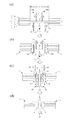
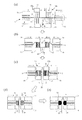
以下、図面を参照しながら、本発明を実施の形態に基づき説明する。図1は本発明による電解質膜耳部分の処理方法の第1の形態を説明する図であり、図2は本発明による電解質膜耳部分の処理方法の第2の形態を説明する図である。 Hereinafter, the present invention will be described based on embodiments with reference to the drawings. FIG. 1 is a diagram for explaining a first embodiment of a method for treating an electrolyte membrane ear portion according to the present invention, and FIG. 2 is a diagram for explaining a second embodiment of a method for treating an electrolyte membrane ear portion according to the present invention.
図1において、1は帯状の電解質膜であり、図示しない送り装置で送られることにより、図示しない原反ロールから巻き出される。巻き出されてくる帯状の電解質膜1の両面には、従来知られた方法により、所定距離aをおいて触媒層2およびガス拡散層3が順次積層されて電極層が形成される。それにより、図1(a)に示すように、帯状の電解質膜1には、複数個の膜電極接合体5が距離aをおいて連続して形成されることとなり、隣接する膜電極接合体5,5の間には、前記距離aに相当する長さの触媒層2等が積層されていない電解質膜部分が存在するようになる。この触媒層2等が積層されていない電解質膜部分を、本発明では、「電解質膜耳部分1a」という。
In FIG. 1, 1 is a belt-shaped electrolyte membrane, and is unwound from a raw roll (not shown) by being fed by a feeding device (not shown). The
本発明の方法を実施する装置において、連続する膜電極接合体5を形成する過程において前記電解質膜耳部分1aが位置することとなる部位には、一対の折り込みブレード10a,10bと、該一対の折り込みブレード10a,10bの間に位置する切断ブレード20を備えている。図1に示す例において、各折り込みブレード10は、電解質膜耳部分1aを挟んで位置する2枚の板部材11,11を有する。2枚の板部材11,11は電解質膜耳部分1aを挟んで上下に離間した位置と、互いに交叉する位置との2位置を選択的に取り得るようにされているとともに、適宜の手段によりそれ自体が電解質膜1の溶融温度以上の温度に加熱されるようになっている。また、切断ブレード20も、電解質膜耳部分1aの下方に退避した位置と、電解質膜耳部分1aを越えて上昇した上昇位置との2位置を選択的に取りうるようにされている。場合によっては、切断ブレード20にも加熱手段を備えてもよい。
In the apparatus for carrying out the method of the present invention, a portion where the electrolyte membrane ear portion 1a is located in the process of forming the continuous
電解質膜耳部分の処理を開始するに際し、図示しない制御機構を操作して、図1(a)に示すように、折り込みブレード10a,10bの板部材11,11および切断ブレード20を、前記電解質膜耳部分1aに近接した位置に移動させる。その状態で、帯状の電解質膜1の送り装置の送りを開放した状態とし、図1(b)に示すように、折り込みブレード10a,10bにおける上下に隔離している板部材11,11とを、互いに交叉する位置まで移動させる。それにより、電解質膜耳部分1aは、その2箇所において折り込まれた状態となる。
When starting the processing of the electrolyte membrane ear portion, a control mechanism (not shown) is operated, and the
次に、切断ブレード20を、図1(b)に示す電解質膜耳部分1aの下方に退避した位置から、図1(c)に示す電解質膜耳部分1aを越えて上昇した上昇位置まで、移動させる。その移動により、電解質膜耳部分1aの折り込みブレード10a,10bの間に位置する部分は、上方に持ち上げられるとともに、その過程で切断される。移動とともに板部材11,11を加熱する。必要な場合には、付加的に局所加熱できる加熱手段30を折り込み部の近傍に配置し、さらに加熱する。電解質膜耳部分1aが溶融した時点で、板部材11,11を元の位置に引き抜く。加熱手段30としては、マイクロ波による加熱手段、赤外線による加熱手段などが好ましい。
Next, the
それにより、加熱により、電解質膜耳部分1aは溶融して、図1(d)に示すように、それぞれの膜電極接合体5の端部、すなわち触媒層2およびガス拡散層3が順次積層されて構成される電極層の端部を、シールした状態で覆うようになる。すなわち、別途ガスケット剤を用いることなく、電解質膜耳部分1aは加熱溶融されて膜電極接合体5の端部ガスケット6として加工される。さらに、加熱の度合いにより、ガスケット化した電解質の物性を変化させることも可能であり、所望の高いガスケット機能を保持させることもできる。最後に、切断ブレード20を退避位置に戻すことにより、本発明による電解質膜耳部分の処理は終了する。
As a result, the electrolyte membrane ear portion 1a is melted by heating, and the end portions of the
図2に示す処理装置は、さらに、折り込みブレード10の横移動を制御する機構15と、形成された膜電極接合体5の横移動を制御する機構16を備える点で、図1に示した装置と相違する。この装置を用いて本発明の方法を実施するに当たっては、帯状の電解質膜1の送り装置の送りを開放するとともに、図2(a)に示すように、膜電極接合体横移動機構16によって、膜電極接合体5を挟持する。さらに、折り込みブレード10の板部材11,11および切断ブレード20を電解質膜耳部分1aに近接した位置に移動させる。
The processing apparatus shown in FIG. 2 further includes a
その姿勢で、折り込みブレード10a,10bにおける上下に隔離している板部材11,11を、互いに交叉する位置まで移動させる。その移動に合わせて、図2(b)に示すように、対向する折り込みブレード横移動機構15、15、および対向する膜電極接合体横移動機構16、16を、互いに接近する方向に所要の距離だけ移動させる。移動距離は、電解質膜耳部分1aの部分が、無理のない状態で前記折り込みブレード10a,10bによって所要に折り込まれるだけの距離であることが好ましい。それにより、引っ張りにより不用意に電解質膜耳部分1aが破断するのを回避することができる。
In this posture, the
次に、図2(c)に示すように、切断ブレード20を下方に退避した位置から電解質膜耳部分1aを越えて上昇した上昇位置まで移動させ、電解質膜耳部分1aを切断する。切断後、膜電極接合体横移動機構16、16をさらに互いに近接する方向に横移動させて、膜電極接合体5、5の端部が折り込みブレード10a,10bに接触した姿勢とし、その姿勢で折り込みブレード10a,10bを引き抜く。それにより、電解質膜耳部分1aは折り込まれた姿勢をそのまま維持した状態で、膜電極接合体5の端部と切断ブレード20との間に保持される。
Next, as shown in FIG. 2 (c), the
次に、図2(d)に示すように、前記した局所的加熱手段30を前記折り込まれた電解質膜耳部分1aに近接させ加熱する。必要に応じて、さらに膜電極接合体横移動機構16、16を近接する方向に横移動させる。それにより、図2(e)に示すように、折り込まれた電解質膜耳部分1a部分は溶融して一体化し、同時に、それぞれの膜電極接合体5の端部を、シールした状態で覆うようになる。すなわち、図1に示した場合と同様に、電解質膜耳部分1aは加熱溶融されて膜電極接合体5の端部ガスケット6として加工される。この場合、加熱の度合いにより、ガスケット化した電解質の物性を変化させることも可能であり、所望の高いガスケット機能を保持させることもできる。最後に、切断ブレード20を退避位置に戻すことにより、本発明による電解質膜耳部分の処理は終了する。
Next, as shown in FIG. 2D, the above-mentioned local heating means 30 is brought close to the folded electrolyte membrane ear portion 1a and heated. If necessary, the membrane electrode assembly
なお、図示しないが、前記局所的加熱手段30が電解質膜耳部分1aの折り込まれた部分に対向する面を、電解質膜耳部分が加熱溶融して形成される端部ガスケット部の形状に沿う形状としておくことにより、所望の形状の端部構造を得ることができる。 Although not shown, the surface of the local heating means 30 facing the folded portion of the electrolyte membrane ear portion 1a is shaped along the shape of the end gasket portion formed by heating and melting the electrolyte membrane ear portion. Thus, an end structure having a desired shape can be obtained.
1…帯状の電解質膜、
1a…触媒層等が積層されていない電解質膜部分(本発明での電解質膜耳部分)
2…触媒層、
3…ガス拡散層、
5…膜電極接合体、
6…電解質樹脂で作られた端部ガスケット、
10a,10b…一対の折り込みブレード、
11…折り込みブレードの板部材、
15…折り込みブレード横移動機構、
16…膜電極接合体横移動機構、
20…切断ブレード、
30…局所加熱できる加熱手段、
1 ... strip-shaped electrolyte membrane,
1a: Electrolyte membrane portion where catalyst layer or the like is not laminated (electrolyte membrane ear portion in the present invention)
2 ... Catalyst layer,
3 ... Gas diffusion layer,
5 ... Membrane electrode assembly,
6 ... End gasket made of electrolyte resin,
10a, 10b ... a pair of folding blades,
11: plate member of the folding blade,
15 ... Folding blade lateral movement mechanism,
16 ... Membrane electrode assembly lateral movement mechanism,
20: Cutting blade,
30 ... Heating means capable of local heating,
Claims (1)
前記電解質膜耳部分に対となる折り込みブレードを挿入して電解質膜耳部分の折り込みを行う工程と、
対となる折り込みブレードの間に切断ブレードを挿入して電解質膜耳部分を切断する工程と、
折り込まれた電解質膜耳部分を加熱溶融して膜電極接合体の端部ガスケットとする工程と、を少なくとも含むことを特長とする電解質膜耳部分の処理方法。 A method for treating an electrolyte membrane ear portion in which a catalyst layer is not formed in a membrane electrode assembly in which an electrode layer comprising a catalyst layer and a diffusion layer is continuously formed on both surfaces of a roll-shaped electrolyte membrane,
Inserting a pair of folding blades into the electrolyte membrane ear portion to fold the electrolyte membrane ear portion; and
Inserting the cutting blade between the pair of folding blades to cut the electrolyte membrane ear portion; and
And a step of heating and melting the folded electrolyte membrane ear portion to form an end gasket of the membrane electrode assembly.
Priority Applications (1)
| Application Number | Priority Date | Filing Date | Title |
|---|---|---|---|
| JP2008321338A JP2010146814A (en) | 2008-12-17 | 2008-12-17 | Processing method of electrolyte membrane selvage in membrane electrode assembly |
Applications Claiming Priority (1)
| Application Number | Priority Date | Filing Date | Title |
|---|---|---|---|
| JP2008321338A JP2010146814A (en) | 2008-12-17 | 2008-12-17 | Processing method of electrolyte membrane selvage in membrane electrode assembly |
Publications (1)
| Publication Number | Publication Date |
|---|---|
| JP2010146814A true JP2010146814A (en) | 2010-07-01 |
Family
ID=42567013
Family Applications (1)
| Application Number | Title | Priority Date | Filing Date |
|---|---|---|---|
| JP2008321338A Pending JP2010146814A (en) | 2008-12-17 | 2008-12-17 | Processing method of electrolyte membrane selvage in membrane electrode assembly |
Country Status (1)
| Country | Link |
|---|---|
| JP (1) | JP2010146814A (en) |
Cited By (1)
| Publication number | Priority date | Publication date | Assignee | Title |
|---|---|---|---|---|
| JP2017142927A (en) * | 2016-02-09 | 2017-08-17 | トヨタ自動車株式会社 | Method for producing a single fuel cell |
-
2008
- 2008-12-17 JP JP2008321338A patent/JP2010146814A/en active Pending
Cited By (1)
| Publication number | Priority date | Publication date | Assignee | Title |
|---|---|---|---|---|
| JP2017142927A (en) * | 2016-02-09 | 2017-08-17 | トヨタ自動車株式会社 | Method for producing a single fuel cell |
Similar Documents
| Publication | Publication Date | Title |
|---|---|---|
| US20210098751A1 (en) | Apparatus and Method of Folding Pouch Case of Battery Cell | |
| US10147962B2 (en) | Method for producing fuel cell membrane electrode assembly | |
| JP5421227B2 (en) | Manufacturing method, manufacturing apparatus and fuel cell for gas diffusion layer of fuel cell | |
| KR20210038333A (en) | Folding apparatus and method for pouch case of battery cell | |
| US20120276435A1 (en) | Method of forming encapsulated solid electrochemical component | |
| JP2007119322A (en) | Glass roll and method for producing glass substrate with functional film using the same | |
| JP6020147B2 (en) | Cutting apparatus and cutting method | |
| CN108352546B (en) | Manufacturing apparatus and method for channel plates | |
| JP2015156445A (en) | Lamination type film capacitor, and method for manufacturing lamination type film capacitor | |
| JP2008198526A (en) | Method for producing gas diffusion layer integrated membrane electrode assembly | |
| JP5708531B2 (en) | Membrane electrode assembly manufacturing method and manufacturing apparatus thereof. | |
| US10141578B2 (en) | Method for producing fuel cell membrane electrode assembly | |
| US20230369633A1 (en) | Apparatus and Method of Folding Pouch Case of Battery Cell | |
| JP5686816B2 (en) | Method for manufacturing a system in which the structural height of a plurality of cells is reduced | |
| JP5257590B2 (en) | Membrane-electrode assembly manufacturing method for fuel cell | |
| JPWO2017191787A1 (en) | Fuel cell manufacturing method and fuel cell | |
| JP2018081808A (en) | Manufacturing method of film assembly | |
| WO2013084512A1 (en) | Method for producing steel sheet for press molding, and method and device for producing press-molded component | |
| CN109950553B (en) | Electrode bonding method and electrode bonding apparatus | |
| JP5163003B2 (en) | Manufacturing method of fuel cell | |
| JP2015153538A (en) | Electrode cutting device | |
| JP2018026274A (en) | Manufacturing method of separator-integrated electrode plate | |
| JP4656602B2 (en) | Cutting device and cutting method for green sheet laminate | |
| KR102941643B1 (en) | Unit cell, method and apparatus for manufacturing unit cell | |
| KR102523115B1 (en) | Manufacturing method of electrode assembly for secondary batteries |