JP2010144592A - Ignition control device, control method and ignition device for internal combustion engine - Google Patents
Ignition control device, control method and ignition device for internal combustion engine Download PDFInfo
- Publication number
- JP2010144592A JP2010144592A JP2008321714A JP2008321714A JP2010144592A JP 2010144592 A JP2010144592 A JP 2010144592A JP 2008321714 A JP2008321714 A JP 2008321714A JP 2008321714 A JP2008321714 A JP 2008321714A JP 2010144592 A JP2010144592 A JP 2010144592A
- Authority
- JP
- Japan
- Prior art keywords
- ignition
- discharge
- spark
- internal combustion
- combustion engine
- Prior art date
- Legal status (The legal status is an assumption and is not a legal conclusion. Google has not performed a legal analysis and makes no representation as to the accuracy of the status listed.)
- Pending
Links
- 238000002485 combustion reaction Methods 0.000 title claims abstract description 41
- 238000000034 method Methods 0.000 title abstract description 8
- 230000000694 effects Effects 0.000 abstract description 6
- 230000001737 promoting effect Effects 0.000 abstract description 2
- 238000010304 firing Methods 0.000 abstract 2
- 230000002708 enhancing effect Effects 0.000 abstract 1
- 239000000446 fuel Substances 0.000 description 15
- 238000002347 injection Methods 0.000 description 10
- 239000007924 injection Substances 0.000 description 10
- 230000015556 catabolic process Effects 0.000 description 7
- 239000000203 mixture Substances 0.000 description 7
- 238000007664 blowing Methods 0.000 description 6
- 239000003990 capacitor Substances 0.000 description 4
- 238000007906 compression Methods 0.000 description 4
- 239000003054 catalyst Substances 0.000 description 3
- 230000006866 deterioration Effects 0.000 description 3
- 238000004804 winding Methods 0.000 description 3
- 230000006835 compression Effects 0.000 description 2
- XLYOFNOQVPJJNP-UHFFFAOYSA-N water Substances O XLYOFNOQVPJJNP-UHFFFAOYSA-N 0.000 description 2
- 239000002826 coolant Substances 0.000 description 1
- 238000001816 cooling Methods 0.000 description 1
- 239000000498 cooling water Substances 0.000 description 1
- 238000010586 diagram Methods 0.000 description 1
- 230000005674 electromagnetic induction Effects 0.000 description 1
- 238000005265 energy consumption Methods 0.000 description 1
- 230000001771 impaired effect Effects 0.000 description 1
- 230000006911 nucleation Effects 0.000 description 1
- 238000010899 nucleation Methods 0.000 description 1
- 238000000746 purification Methods 0.000 description 1
- 238000004904 shortening Methods 0.000 description 1
- 230000001960 triggered effect Effects 0.000 description 1
Images

Landscapes
- Ignition Installations For Internal Combustion Engines (AREA)
- Spark Plugs (AREA)
Abstract
Description
本発明はエンジンの点火制御に関する。より具体的には火花放電経路を拡大して着火性を向上するための点火制御方法に関する。 The present invention relates to engine ignition control. More specifically, the present invention relates to an ignition control method for improving spark ignitability by expanding a spark discharge path.
火花点火式内燃機関の理想的な点火状態は燃焼室の中心付近で火種が発生し、混合気の中心から火炎が燃え拡がることである。これにより、燃焼室壁面への熱損失低減,燃焼期間(時間損失)の短縮,ノッキング抑制などに効果がある。通常の火花放電では、点火プラグ自体を長くすることで、この理想状態を模擬的に作り出しているが、プラグ突き出しによる耐久性悪化などの問題がある。 The ideal ignition state of a spark ignition type internal combustion engine is that a fire type is generated near the center of the combustion chamber, and a flame spreads from the center of the air-fuel mixture. This is effective in reducing heat loss to the combustion chamber wall surface, shortening the combustion period (time loss), suppressing knocking, and the like. In normal spark discharge, this ideal state is simulated by lengthening the spark plug itself, but there are problems such as deterioration in durability due to the plug sticking out.
一方、特開2008−45449号公報で紹介されているようなプラズマ放電点火では、放電距離が長いという特徴があり近年注目されている。しかし、背圧の上昇に伴い放電距離が短くなるという欠点があり、エンジン燃焼室内の現象に関して言えば、種々に変化する運転環境下で、筒内圧力の上昇に伴い放電距離が短くなり、着火点が燃焼室の壁面近傍になってしまう。その結果、壁面からの熱損失が大きくなり、火炎伝播(初期燃焼)が遅くなるという問題がある。 On the other hand, plasma discharge ignition as introduced in Japanese Patent Application Laid-Open No. 2008-45449 is characterized by a long discharge distance and has been attracting attention in recent years. However, there is a disadvantage that the discharge distance becomes shorter as the back pressure increases. With regard to the phenomenon in the engine combustion chamber, the discharge distance becomes shorter as the in-cylinder pressure increases under the various operating conditions, and the ignition point is reduced. Becomes near the wall surface of the combustion chamber. As a result, there is a problem that heat loss from the wall surface increases and flame propagation (initial combustion) becomes slow.
また、エンジン燃焼室内の混合気への着火性向上手段として、火花放電経路(距離)を拡大して、空間的な着火機会を増加し着火性を向上させることが知られている。一例として、プラグギャップ(電極間隙間)を拡大する取り組みが行われているが、プラグギャップを拡大すると火花放電時に必要となる要求放電電圧が上がり飛火性が悪化する。さらに、スロットル弁が全開となる高負荷運転時には、要求放電電圧の上昇とともに燃焼室内の空気流動も強くなるために、火花放電が吹き流されて失火する恐れがあり、現実的には極端なワイドギャップ化は行われずに、通常は0.9〜1.3mm程度のギャップとなっている。別の例として、燃焼室内の空気流動を利用する方法も考えられている。これは点火プラグ近傍に流れる流動で、火花放電時のアークを吹き流し、放電距離を拡大する試みである。しかし、吸気工程中に発生した空気流動を圧縮工程後半の点火時期まで保存することは困難であり、空気流動を適切なタイミングで点火プラグ近傍に導くのも困難で、アークを制御しているとは言い難い状態であった。 Further, as means for improving the ignitability of the air-fuel mixture in the engine combustion chamber, it is known that the spark discharge path (distance) is expanded to increase spatial ignition opportunities and improve the ignitability. As an example, efforts are being made to increase the plug gap (interelectrode gap). However, if the plug gap is increased, the required discharge voltage required during spark discharge increases and the spark performance deteriorates. Furthermore, during high load operation with the throttle valve fully open, the air flow in the combustion chamber becomes stronger as the required discharge voltage rises. The gap is not formed, and the gap is usually about 0.9 to 1.3 mm. As another example, a method using an air flow in a combustion chamber is also considered. This is a flow that flows in the vicinity of the spark plug, and is an attempt to expand the discharge distance by blowing an arc during spark discharge. However, it is difficult to store the air flow generated during the intake process until the ignition timing in the second half of the compression process, and it is difficult to guide the air flow to the vicinity of the spark plug at an appropriate timing, and the arc is controlled. It was hard to say.
背景技術で述べたように、燃焼室の中心付近で火種が発生し火炎伝播するという理想的な燃焼状態を実現するため、点火プラグ自体を長くしたり、プラズマ放電点火などが考案されているが、耐久性や運転状態によって着火点が変化してしまうなど、十分なエンジン性能を発揮できていない。また、エンジン燃焼室内の混合気への着火性向上手段として、ワイドギャップ化や空気流動を利用して火花放電経路(距離)を拡大して、空間的な着火機会を増加することが試されているが、要求放電電圧の上昇による飛火性悪化,圧縮工程後半での空気流動制御性の困難さなどが原因で、着火性向上によるエンジン性能の向上も十分に行われていない。 As described in the background art, in order to realize an ideal combustion state in which a fire type is generated near the center of the combustion chamber and the flame propagates, it has been devised that the spark plug itself is lengthened, plasma discharge ignition, etc. However, sufficient engine performance is not being demonstrated, such as the ignition point changing depending on durability and driving conditions. In addition, as a means to improve the ignitability of the air-fuel mixture in the engine combustion chamber, it has been tried to increase the spark ignition path (distance) by using a wide gap and air flow to increase spatial ignition opportunities. However, the engine performance has not been sufficiently improved by improving the ignitability due to the deterioration of the flying performance due to the increase in the required discharge voltage and the difficulty of the air flow controllability in the latter half of the compression process.
そこで本発明では、火花放電(アーク)の放電経路を拡大して、着火性を向上するとともに、着火点を燃焼室壁面から出来るだけ離し、火炎伝播を促進できる点火プラグ構成,回路構成および点火制御方法を提供することを目的とする。より具体的には、プラズマジェットの吹き出し効果を利用して、火花放電(アーク)の放電経路を拡大している。そのための火花放電とプラズマ放電を組み合わせたハイブリット型の点火プラグ形状も提案している。特開2007−32349号公報には、主電極と補助電極を有し火花放電(アーク)前にプラズマを放電して、点火プラグの放電領域にプラズマ雰囲気を生成させて、火花放電を起こしやすくすることが可能なハイブリット型点火プラグの例が提案されている。 Therefore, in the present invention, a spark discharge (arc) discharge path is expanded to improve ignitability, and an ignition plug configuration, circuit configuration, and ignition control method capable of promoting flame propagation by separating the ignition point from the combustion chamber wall surface as much as possible. The purpose is to provide. More specifically, the discharge path of the spark discharge (arc) is expanded by utilizing the plasma jet blowing effect. For this purpose, a hybrid spark plug shape combining spark discharge and plasma discharge has also been proposed. Japanese Patent Application Laid-Open No. 2007-32349 has a main electrode and an auxiliary electrode, discharges plasma before spark discharge (arc), and generates a plasma atmosphere in the discharge region of the spark plug, thereby facilitating spark discharge. An example of a hybrid spark plug that can be used has been proposed.
本発明では、プラズマ放電の吹き出し効果を利用して、火花放電(アーク)の放電経路を吹き出し着火性を向上させる。そのために適切なタイミングで火花放電(アーク)とプラズマ放電を吹き出すためのプラグ構成,回路構成、および点火制御方法を提供することを目的とする。具体的なプラグ構造,回路構成は「発明の実施の形態」に記載する。 In the present invention, the spark discharge effect of the plasma discharge is utilized to improve the spark ignitability of the discharge path of the spark discharge (arc). Therefore, it is an object to provide a plug configuration, a circuit configuration, and an ignition control method for blowing out spark discharge (arc) and plasma discharge at an appropriate timing. A specific plug structure and circuit configuration are described in “Embodiments of the Invention”.
上記の目的を達するために、本発明の内燃機関の点火装置は、1つの接地電極に対して2つの中心電極を有し、前記接地電極と一方の中心電極(A)間に火花放電を発生させ、前記接地電極と他方の中心電極(B)間にプラズマ放電を発生させ、前記火花放電の放電方向が前記プラズマ放電の放電方向とほぼ直交する構成となっている。このハイブリット型点火プラグへの点火指令はエンジン制御ユニット(ECU)から行われ、ECUからは火花放電を起こすための点火信号とプラズマ放電を起こすための点火信号が出力される構成となっている。 To achieve the above object, the ignition device for an internal combustion engine of the present invention has two center electrodes for one ground electrode, and generates a spark discharge between the ground electrode and one center electrode (A). The plasma discharge is generated between the ground electrode and the other center electrode (B), and the discharge direction of the spark discharge is substantially orthogonal to the discharge direction of the plasma discharge. An ignition command to the hybrid type spark plug is issued from an engine control unit (ECU), and an ignition signal for causing spark discharge and an ignition signal for causing plasma discharge are outputted from the ECU.
本発明の内燃機関の点火装置および点火制御装置,制御方法によれば、エンジンの所謂“点火時期”直後に火花放電が起こり、それから所定のタイミングでプラズマ放電が起こり、両者の相乗効果により火花放電(アーク)の放電経路が長くなり着火性が向上するとともに、そのアークが燃焼室中心方向に吹き出されるため、着火点が燃焼室壁面から離れる結果、壁面への冷却損失が低減するとともに火炎伝播速度が向上し、理想的な燃焼状態を実現でき、燃費効率向上に寄与することが可能となる。 According to the internal combustion engine ignition device, ignition control device, and control method of the present invention, a spark discharge occurs immediately after the so-called “ignition timing” of the engine, and then a plasma discharge occurs at a predetermined timing. (Arc) discharge path becomes longer and ignitability is improved, and the arc is blown out toward the center of the combustion chamber. As a result, the ignition point moves away from the wall surface of the combustion chamber, resulting in reduced cooling loss to the wall surface and flame propagation speed. As a result, an ideal combustion state can be realized, which contributes to an improvement in fuel efficiency.
さらに、火花放電,プラズマ放電をそれぞれ単独で使用する場合に比べて、混合気への供給エネルギは増大し着火性が向上する。また、プラズマ放電を単独で使用する場合と比較して、メインの火炎核形成は火花放電で行い、アークの吹き出し効果に利用するだけのエネルギをプラズマ放電から供給すれば良いため、プラグの消耗を抑えることにも効果がある。 Furthermore, compared with the case where spark discharge and plasma discharge are used individually, the supply energy to the air-fuel mixture is increased and the ignitability is improved. Compared to the case of using plasma discharge alone, main flame nucleation is performed by spark discharge, and it is sufficient to supply energy from the plasma discharge to use the arc blowing effect. It is also effective to suppress.
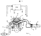
本発明の実施例を図を用いて説明する。図1は本発明を適用するエンジンシステムの構成例である。まず、エンジン1の基本動作について説明する。エンジン1に吸入される空気は図示しないエアクリーナを通り、吸気ダクトに取り付けられたエアフローセンサ2により吸入空気量が計測される。エンジン1に吸入される空気量はスロットル弁3で制御される。吸気コレクタ5は図示しない他気筒へ空気を分配するためのもので、その後、各気筒の吸気管に空気が分配され、燃焼室22に空気が吸入される。吸気管9の途中には、空気流に指向性を持たせるための空気流動制御弁6を用いても良い。ECU10はエンジン1に取り付けられた各種センサからの信号を基に、ECU10内部でエンジン1の運転状況を判定し、その運転状況に相応しい指令値を各種アクチュエータに出力する。ここで各種センサの例としては、エアフローセンサ2,吸気カム位相を検出するフェーズセンサ7,排気カム位相を検出するフェーズセンサ8,クランク軸25の回転数を検出するクランク角センサ26,エンジン冷却水温度を検出する水温センサ21,ノッキングを検出するノックセンサ16,排気管18内の排気ガス濃度を検出する(図示しない)排ガスセンサ、などである。また、各種アクチュエータの例としては、スロットル弁3,空気流動制御弁6,吸気および排気のカム位相を制御する(図示しない)位相制御弁,点火コイル12,燃料噴射弁19、などである。エアフローセンサ2により計測された空気量、および排気センサの出力に基づいて、ECU10は燃料噴射量を算出し、燃料噴射弁19に噴射信号を出力する。噴射信号は主に噴射時期,噴射回数,噴射期間で構成されている。燃焼室22に供給された空気と燃料は、ピストン23の上下動に伴い、燃焼室22内で気化,混合して混合気を形成する。その後ピストン23の圧縮動作により、温度と圧力が上昇する。ECU10はエンジン回転数,燃料噴射量などの情報から点火時期を算出し、点火コイル12に点火信号を出力する。点火信号は主に点火コイル12への通電開始時期,通電終了時期で構成されている。これにより、ピストン23の圧縮上死点の少し手前のタイミングで点火プラグ15により点火が行われ、燃焼室22内の混合気に着火し燃焼が起こる。燃焼により高まった圧力により、ピストン23を下方向に押し返す力が働き、膨張行程でエンジントルクとしてクランク軸25に伝達され、エンジン動力となる。燃焼終了後、燃焼室22に残留したガスは、排気弁14を通り排気管18に排出される。この排気ガスには人体に有害な成分が含まれることが多いので、排気管18の途中に配置された触媒11,17の作用により無害化され、大気中に排出される。
Embodiments of the present invention will be described with reference to the drawings. FIG. 1 shows a configuration example of an engine system to which the present invention is applied. First, the basic operation of the
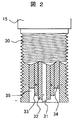
次に、点火プラグ15の先端部の形状を図2に示す。点火プラグ15はネジ部を有する外側接地電極30により、エンジンに取り付けられる。ここではエンジン本体が接地されていると仮定する。従って、外側接地電極30は図中に示すようにマイナス電位となる。一方、中心電極31は点火コイル12に接続されており、点火時期にプラス電位の高電圧が掛かり、外側接地電極30との間に火花放電が起こる。中心電極33はプラズマ放電用の電極で、外側接地電極30との間で絶縁破壊が起こり、その後の電力投入によりプラズマが放電される。中心電極31と33の間には絶縁部材32が挿入されており、中心電極間の接触,電位差によるリークを防止している。中心電極33と外側接地電極30の間にも絶縁部材34が挿入されており、中心電極と接地電極の接触,リークを防止するとともに、中心電極33,絶縁部材34,外側接地電極30で囲まれた閉空間35を形成しており、プラズマ放電する際のキャビティの役割を果たしている。
Next, the shape of the tip of the
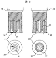
図3に火花放電,プラズマ放電の様子を模式的に示す。図3左の図は火花放電の様子を示したもので、図示しない点火コイル12の作用により、中心電極31にプラス電位の高電圧が掛かり、外側接地電極30との間で絶縁破壊が起こり、それに引き続いてアーク27が形成される。火花放電27は、外側接地電極30の特定の場所で発生する訳ではなく、毎回発生する場所が変化し、アーク発生中も移動しながら火花放電を継続する。従って、外側接地電極30の特定の場所だけが劣化して機能が損なわれることは無い。図3右の図はプラズマ放電の様子を示したもので、図示しないプラズマ放電用回路の作用により、中心電極33と外側接地電極30の間で絶縁破壊が起こり、それに引き続く電力投入で閉空間35内の温度が上昇し、それに伴い局所的に圧力が上昇しプラズマ放電28が生じる。閉空間35の形状から、プラズマ放電28の形状は環状となる。この2つ点火現象を組み合わせることで、アーク27の放電経路をプラズマ放電28により押し出し、放電経路を拡大し、混合気との着火機会を増大させる。
FIG. 3 schematically shows the state of spark discharge and plasma discharge. The figure on the left side of FIG. 3 shows the state of spark discharge. Due to the action of the ignition coil 12 (not shown), a high positive voltage is applied to the
点火プラグの構成は、図2,図3に示した構造に限定されるものではなく、様々な改良が加えられるが、本発明の効果を十分に引き出すために、プラズマ放電方向とほぼ直交する方向に火花放電を行う点火プラグの構成とすることが望ましい。 The structure of the spark plug is not limited to the structure shown in FIGS. 2 and 3, and various improvements can be made. However, in order to sufficiently bring out the effects of the present invention, the direction substantially perpendicular to the plasma discharge direction is used. It is desirable to have a configuration of a spark plug that performs spark discharge.
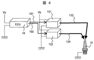
図4に回路構成例を示す。ECU10には図示しない各種センサからの入力信号と、バッテリ電源Vbおよび接地配線が施されている。点火プラグ15は火花放電用中心電極とプラズマ放電用中心電極を持つハイブリット型の構成となっている。火花放電用点火回路121は内部に1次コイル(巻線)と2次コイル(巻線)を有する構造で、ECU10からの点火信号101に基づき、通電開始時期に1次コイルに通電を開始し電気エネルギを充電する。通電終了時期に1次コイルへの通電が遮断されると、電磁誘導の作用により2次コイルに高電圧となった電気エネルギが発生し、点火プラグ15で火花放電が起こる。プラズマ放電用点火回路122は特公昭60−52311号の図1に記載される回路が一般的によく使用されている。これはECU10からの点火信号102に基づいて、最初にプラズマ放電用回路内に有する“スパーク点火用電源回路”から点火プラグ15内の中心電極33と外側接地電極30の間で絶縁破壊するためのエネルギを供給する。その間、プラズマ放電用回路内に有するコンデンサには電荷がチャージされている。絶縁破壊が起こり、中心電極33と接地電極30間が通電するとコンデンサにチャージされた電荷が一気に流れ、閉空間35内が高温,高圧になり、短時間でプラズマ放電が発生する。
FIG. 4 shows a circuit configuration example. The
このときの点火信号およびケーブル123,124に流れる電流の様子を図5に示す。図中IGNが所謂“点火時期”である。点火信号101は火花放電用の点火信号で、IGNよりT1前から1次コイルへの通電を開始し、IGNで1次コイルへの通電遮断により、2次コイルに高電圧となった電気エネルギが発生し、点火プラグ15の中心電極31と外側接地電極30間にアークが流れる。そのときケーブル123に流れる電流波形は、IGN直後にピークとなる三角形の波形となり、その放電時間はt1となる。t1は1次コイル,2次コイルの巻線比で変更することが可能である。一般的には、T1は2〜3ms、t1は50〜100ms程度の値となる。一方、点火信号102はプラズマ放電用の点火信号で、IGNをトリガーにして、プラズマ放電用回路内に有する“スパーク点火用電源回路”から供給されたエネルギで中心電極33と外側接地電極30間で絶縁破壊が生じ、それに引き続いてコンデンサにチャージされていた電荷がプラズマ放電する。そのときケーブル124に流れる電流はIGNからt2遅れて立ち上がり、t3で放電が終了する。t2およびt3はプラズマ放電用回路内の設定で変更可能であるが、t2は0.01ms,t3は0.05ms程度の値である。
The state of the ignition signal and the current flowing through the
以上の点火プラグおよび回路構成とすることで、プラズマ放電の吹き出し効果を利用して、火花放電(アーク)の放電経路を吹き出し着火性を向上させることが可能となる。火花放電(アーク)の吹き出し量,持続時間が適切な量,時間となるように、T1およびt1〜3で調整する。また、火花放電(アーク)の吹き出しが不要な運転条件では、プラズマ放電を停止することで、アークの吹き出しは無くなり通常の火花放電型の点火システムとして機能する。これによりプラズマ放電のためのエネルギ消費を削減でき、点火プラグの劣化防止,耐久性向上,燃費向上に効果がある。 With the above spark plug and circuit configuration, it is possible to improve the spark ignitability of the discharge path of the spark discharge (arc) using the plasma discharge blowing effect. Adjustments are made at T1 and t1 to t3 so that the amount and duration of spark discharge (arc) blowing are appropriate. Also, under operating conditions that do not require the discharge of spark discharge (arc), by stopping plasma discharge, the discharge of arc disappears and functions as a normal spark discharge type ignition system. This can reduce energy consumption for plasma discharge, and is effective in preventing deterioration of the spark plug, improving durability, and improving fuel consumption.
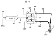
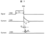
図6には別の回路構成例を示す。図4に示した回路構成に対して、点火信号制御装置125を追加した回路構成となっている。その他は図4の回路構成例と同じであるので説明は省略するが、ECU10が点火信号103のみを出力する点が異なっている。従って、1気筒当たりに使用するピン数,配線数などを半減することが可能となる。点火プラグ15は火花放電用中心電極とプラズマ放電用中心電極を持つハイブリット構成となっている。図7を用いて、点火信号制御装置125の機能を中心に説明する。点火信号103は火花放電用の点火信号で、それを受けた点火信号制御装置125は、火花放電用点火回路121に1次コイルへの通電を開始/終了する制御信号を出力する。点火信号制御装置125は、点火信号103の信号立下り位置をトリガーにして、プラズマ放電用点火回路122に信号を出力する。プラズマ放電用点火回路122内に有する“スパーク点火用電源回路”から供給されたエネルギで中心電極33と外側接地電極30間で絶縁破壊が生じ、それに引き続いてコンデンサにチャージされていた電荷がプラズマ放電する。そのときケーブル124に流れる電流はIGNからt2遅れて立ち上がり、t3で放電が終了する。t2およびt3はプラズマ放電用回路内の設定で変更可能であるが、t2は0.01ms,t3は0.05ms程度の値である。
FIG. 6 shows another circuit configuration example. A circuit configuration is obtained by adding an ignition
以上の回路構成では、ECU10から出力される点火信号は1気筒当たり1本となるので、既存のエンジンシステムとの置き換えが容易となる。また、点火信号制御装置125を、火花放電用点火回路121,プラズマ放電用点火回路122とともに、一体化して点火制御装置29とした構成としても良い。
With the above circuit configuration, the ignition signal output from the
1 エンジンシステム
2 エアフローセンサ
3 スロットル弁
4 吸気ダクト
5 吸気コレクタ
6 空気流動制御弁
7 吸気カムフェーズセンサ
8 排気カムフェーズセンサ
9 吸気管
10 ECU
11 排気ガス浄化触媒
12 点火コイル
13 吸気弁
14 排気弁
15 点火プラグ
16 ノックセンサ
17 床下触媒
18 排気管
19 燃料噴射弁
20 冷却水通路
21 水温センサ
22 燃焼室
23 ピストン
24 コンロッド
25 クランク軸
26 クランク角センサ
27 火花放電
28 プラズマ放電
29 点火制御装置
30 外側接地電極
31 火花放電用中心電極
32,34 絶縁部材
33 プラズマ放電用中心電極
35 閉空間
101 火花放電用点火信号
102 プラズマ放電用点火信号
103 点火信号
121 火花放電用点火回路
122 プラズマ放電用点火回路
123 火花放電用ケーブル
124 プラズマ放電用ケーブル
125 点火信号制御装置
1
11 Exhaust
Claims (7)
を特徴とする内燃機関の点火制御装置。 There are two center electrodes for one ground electrode, and two kinds of discharge are generated between the ground electrode and one center electrode (A) and between the ground electrode and the other center electrode (B). An internal combustion engine ignition device is provided for each cylinder, and two types of ignition signals are output per cylinder to the ignition device;
An ignition control device for an internal combustion engine.
を特徴とする内燃機関の点火制御装置。 Of the two types of ignition signals according to claim 1, one is a spark discharge ignition signal and the other is a plasma discharge ignition signal.
An ignition control device for an internal combustion engine.
を特徴とする内燃機関の点火制御装置。 There are two center electrodes for one ground electrode, and two kinds of discharge are generated between the ground electrode and one center electrode (A) and between the ground electrode and the other center electrode (B). An ignition signal control device comprising an internal combustion engine ignition device for each cylinder, outputting one type of ignition signal per cylinder to the ignition device, and generating two types of ignition signals from the one type of ignition signal Having
An ignition control device for an internal combustion engine.
を特徴とする内燃機関の点火制御装置。 Of the two ignition signals according to claim 3, one is a spark discharge ignition signal and the other is a plasma discharge ignition signal.
An internal combustion engine ignition control device.
を特徴とする内燃機関の点火装置。 In an internal combustion engine ignition device including a ground electrode and a center electrode, generating a spark discharge and a plasma discharge between the ground electrode and the center electrode;
An internal combustion engine ignition device.
を特徴とする内燃機関の点火装置。 There are two center electrodes for one ground electrode, a spark discharge is generated between the ground electrode and one center electrode (A), and a plasma discharge is generated between the ground electrode and the other center electrode (B). The discharge direction of the spark discharge is substantially perpendicular to the discharge direction of the plasma discharge,
An internal combustion engine ignition device.
Priority Applications (1)
| Application Number | Priority Date | Filing Date | Title |
|---|---|---|---|
| JP2008321714A JP2010144592A (en) | 2008-12-18 | 2008-12-18 | Ignition control device, control method and ignition device for internal combustion engine |
Applications Claiming Priority (1)
| Application Number | Priority Date | Filing Date | Title |
|---|---|---|---|
| JP2008321714A JP2010144592A (en) | 2008-12-18 | 2008-12-18 | Ignition control device, control method and ignition device for internal combustion engine |
Publications (1)
| Publication Number | Publication Date |
|---|---|
| JP2010144592A true JP2010144592A (en) | 2010-07-01 |
Family
ID=42565280
Family Applications (1)
| Application Number | Title | Priority Date | Filing Date |
|---|---|---|---|
| JP2008321714A Pending JP2010144592A (en) | 2008-12-18 | 2008-12-18 | Ignition control device, control method and ignition device for internal combustion engine |
Country Status (1)
| Country | Link |
|---|---|
| JP (1) | JP2010144592A (en) |
Cited By (3)
| Publication number | Priority date | Publication date | Assignee | Title |
|---|---|---|---|---|
| JP2013185557A (en) * | 2012-03-09 | 2013-09-19 | Nippon Soken Inc | Ignition device for internal combustion engine |
| JP2015516051A (en) * | 2012-05-08 | 2015-06-04 | ローゼンベルガー ホーフフレクベンツテクニーク ゲーエムベーハー ウント ツェーオー カーゲー | High frequency plasma ignition device |
| CN114109614A (en) * | 2021-11-05 | 2022-03-01 | 苏州凯德航空科技有限公司 | Rapid ignition system and ignition method of micro turbojet engine |
Citations (6)
| Publication number | Priority date | Publication date | Assignee | Title |
|---|---|---|---|---|
| JPS50112632A (en) * | 1973-11-29 | 1975-09-04 | ||
| JPH03264772A (en) * | 1989-11-21 | 1991-11-26 | Cummins Engine Co Inc | Method and device for producing highly conductive channel for flow of plasma current |
| JPH11210607A (en) * | 1998-01-27 | 1999-08-03 | Ngk Spark Plug Co Ltd | Ignition device for internal combustion engine and internal combustion engine |
| JP2007032349A (en) * | 2005-07-25 | 2007-02-08 | Denso Corp | Ignition device for internal combustion engine |
| JP2008045449A (en) * | 2006-08-11 | 2008-02-28 | Denso Corp | Ignition device for internal combustion engine |
| JP2008218249A (en) * | 2007-03-06 | 2008-09-18 | Denso Corp | Plasma type ignition device and its manufacturing method |
-
2008
- 2008-12-18 JP JP2008321714A patent/JP2010144592A/en active Pending
Patent Citations (6)
| Publication number | Priority date | Publication date | Assignee | Title |
|---|---|---|---|---|
| JPS50112632A (en) * | 1973-11-29 | 1975-09-04 | ||
| JPH03264772A (en) * | 1989-11-21 | 1991-11-26 | Cummins Engine Co Inc | Method and device for producing highly conductive channel for flow of plasma current |
| JPH11210607A (en) * | 1998-01-27 | 1999-08-03 | Ngk Spark Plug Co Ltd | Ignition device for internal combustion engine and internal combustion engine |
| JP2007032349A (en) * | 2005-07-25 | 2007-02-08 | Denso Corp | Ignition device for internal combustion engine |
| JP2008045449A (en) * | 2006-08-11 | 2008-02-28 | Denso Corp | Ignition device for internal combustion engine |
| JP2008218249A (en) * | 2007-03-06 | 2008-09-18 | Denso Corp | Plasma type ignition device and its manufacturing method |
Cited By (4)
| Publication number | Priority date | Publication date | Assignee | Title |
|---|---|---|---|---|
| JP2013185557A (en) * | 2012-03-09 | 2013-09-19 | Nippon Soken Inc | Ignition device for internal combustion engine |
| JP2015516051A (en) * | 2012-05-08 | 2015-06-04 | ローゼンベルガー ホーフフレクベンツテクニーク ゲーエムベーハー ウント ツェーオー カーゲー | High frequency plasma ignition device |
| CN114109614A (en) * | 2021-11-05 | 2022-03-01 | 苏州凯德航空科技有限公司 | Rapid ignition system and ignition method of micro turbojet engine |
| CN114109614B (en) * | 2021-11-05 | 2024-06-07 | 苏州凯德航空科技有限公司 | Rapid ignition system and ignition method for miniature turbojet engine |
Similar Documents
| Publication | Publication Date | Title |
|---|---|---|
| JP4691373B2 (en) | Spark ignition engine, control device used for the engine, and ignition coil used for the engine | |
| JP2008303841A (en) | Internal combustion engine and control device for internal combustion engine | |
| JP5765493B2 (en) | Ignition device and ignition method for internal combustion engine | |
| CN113825900A (en) | Control device for internal combustion engine | |
| JP5482692B2 (en) | Ignition control device for internal combustion engine | |
| JP6036771B2 (en) | Intake device for internal combustion engine | |
| US11939943B2 (en) | Ignition apparatus for internal combustion engine | |
| JP2010144592A (en) | Ignition control device, control method and ignition device for internal combustion engine | |
| JP6392535B2 (en) | Control device for internal combustion engine | |
| JP4980807B2 (en) | Control device for internal combustion engine | |
| JP5843047B2 (en) | Ignition control device and ignition control method for internal combustion engine | |
| CN110073097B (en) | Ignition control system and ignition control device | |
| WO2021157322A1 (en) | Subsidiary chamber type ignition system | |
| KR20110105240A (en) | Ignition apparatus of internal combustion engine with multiple ignition coils and spark plugs | |
| WO2022030175A1 (en) | Ignition system | |
| JP4939629B2 (en) | Ignition control device for internal combustion engine | |
| JP2013096289A (en) | Spark ignition type internal combustion engine | |
| JP2010116879A (en) | Ignition control device or ignition control method for internal combustion engine | |
| JP6411951B2 (en) | Control device for internal combustion engine | |
| JP2022131765A (en) | ignition controller | |
| JP2016114039A (en) | Ignitor of internal combustion engine | |
| JP7412599B2 (en) | Internal combustion engine control device | |
| JP6531841B2 (en) | Igniter | |
| Lorenz et al. | Advanced Ignition Systems: Technical Possibilities and Limitations | |
| JP6217493B2 (en) | Control unit for direct injection gasoline engine |
Legal Events
| Date | Code | Title | Description |
|---|---|---|---|
| A621 | Written request for application examination |
Free format text: JAPANESE INTERMEDIATE CODE: A621 Effective date: 20100910 |
|
| A521 | Written amendment |
Free format text: JAPANESE INTERMEDIATE CODE: A523 Effective date: 20100910 |
|
| A977 | Report on retrieval |
Effective date: 20110816 Free format text: JAPANESE INTERMEDIATE CODE: A971007 |
|
| A131 | Notification of reasons for refusal |
Effective date: 20110913 Free format text: JAPANESE INTERMEDIATE CODE: A131 |
|
| A521 | Written amendment |
Effective date: 20111110 Free format text: JAPANESE INTERMEDIATE CODE: A523 |
|
| A131 | Notification of reasons for refusal |
Free format text: JAPANESE INTERMEDIATE CODE: A131 Effective date: 20120228 |
|
| A521 | Written amendment |
Effective date: 20120409 Free format text: JAPANESE INTERMEDIATE CODE: A523 |
|
| A02 | Decision of refusal |
Free format text: JAPANESE INTERMEDIATE CODE: A02 Effective date: 20120612 |