JP2010144528A - Compressor - Google Patents
Compressor Download PDFInfo
- Publication number
- JP2010144528A JP2010144528A JP2008319557A JP2008319557A JP2010144528A JP 2010144528 A JP2010144528 A JP 2010144528A JP 2008319557 A JP2008319557 A JP 2008319557A JP 2008319557 A JP2008319557 A JP 2008319557A JP 2010144528 A JP2010144528 A JP 2010144528A
- Authority
- JP
- Japan
- Prior art keywords
- balance weight
- protection member
- motor rotor
- compressor
- electric motor
- Prior art date
- Legal status (The legal status is an assumption and is not a legal conclusion. Google has not performed a legal analysis and makes no representation as to the accuracy of the status listed.)
- Withdrawn
Links
Images


Landscapes
- Applications Or Details Of Rotary Compressors (AREA)
Abstract
【課題】構造を複雑化することなく、バランスウェイトによる撹拌損失を抑えることができ、高い性能を安定して発揮できる圧縮機を提供する。
【解決手段】圧縮機100は、ケーシングと、ケーシング内に垂直方向に収容される電動機ステータ11と、電動機ロータ10と、電動機ロータ10の中心部に挿入され、電動機ロータ10とともに回転駆動するクランク軸6と、電動機ロータ10の底部に取り付けられ、電動機ロータとともに回転するバランスウェイト10aと、バランスウェイト10aの少なくとも底部に取り付けられ、バランスウェイト10aによるケーシング内の冷凍機油14との干渉を防止するためのバランスウェイト保護部材40と、を有している。
【選択図】図5A compressor capable of suppressing agitation loss due to a balance weight without complicating the structure and stably exhibiting high performance is provided.
A compressor 100 includes a casing, an electric motor stator 11 accommodated in the casing in a vertical direction, an electric motor rotor 10, and a crankshaft that is inserted into a central portion of the electric motor rotor 10 and is rotationally driven together with the electric motor rotor 10. 6, the balance weight 10a attached to the bottom of the motor rotor 10 and rotating together with the motor rotor, and attached to at least the bottom of the balance weight 10a, for preventing the balance weight 10a from interfering with the refrigerating machine oil 14 in the casing. And a balance weight protection member 40.
[Selection] Figure 5
Description
本発明は、空気調和装置や冷凍装置等の各種産業機械に用いられる回転式の電動圧縮機に関し、特に電動機ロータ底部にバランスウェイトを備えた圧縮機に関するものである。 The present invention relates to a rotary electric compressor used in various industrial machines such as an air conditioner and a refrigeration apparatus, and more particularly to a compressor having a balance weight at the bottom of an electric motor rotor.
従来から、たとえば冷媒回路において冷媒を圧縮するために用いられる回転式電動圧縮機が存在している(たとえば、特許文献1参照)。また近年、各種産業機械に用いられる圧縮機には、省エネルギーや環境保全等の観点から高効率化や省資源化(小型、軽量化)が求められている。加えて、性能を向上させ、この性能を安定して維持できるように圧縮機が求められている。そのようなものとして、「ケーシング内に、圧縮機構と、該圧縮機構を駆動する電動機と、電動機の駆動軸と一体回転して回転系の動的な質量バランスをとるバランスウェイトとを備えた回転式圧縮機であって、上記バランスウェイトは、全体が円環状に形成されるとともに、周方向の一部分が中実部に、他の一部分が中空部に形成されている回転式圧縮機」が提案されている(たとえば、特許文献2参照)。 Conventionally, for example, there is a rotary electric compressor used for compressing a refrigerant in a refrigerant circuit (see, for example, Patent Document 1). In recent years, compressors used in various industrial machines are required to be highly efficient and save resources (smaller and lighter) from the viewpoints of energy saving and environmental protection. In addition, there is a need for a compressor that improves performance and maintains this performance stably. As such, “a rotation provided in a casing with a compression mechanism, an electric motor that drives the compression mechanism, and a balance weight that rotates integrally with the drive shaft of the electric motor to balance the dynamic mass of the rotating system. A rotary compressor in which the entire balance weight is formed in an annular shape, a part in the circumferential direction is formed in a solid part, and the other part is formed in a hollow part. (For example, see Patent Document 2).
特許文献1に記載されているような圧縮機では、運転中に、ケーシング(密閉容器)の内部にガス冷媒が充満するようになっている。また、特許文献1に記載されているような圧縮機は、ケーシング内底部に圧縮機構や駆動機構の可動部分を潤滑するための冷凍機油が貯留されている。この冷凍機油は、圧縮機運転中には圧縮機上部及び冷媒回路内を循環しているが、圧縮機の運転停止等、冷媒回路内の圧力変化が起こった場合に圧縮機内に戻ってくることがある。
In a compressor as described in
この返油により、圧縮機内で冷凍機油が過多となると、電動機が冷凍機油中と干渉する。これにより、圧縮機のケーシング内に固定される電動機ステータ側面に設けられた返油溝(冷媒及び冷凍機油の循環用)が冷凍機油に浸かり、塞がってしまうことになる。そうなると、圧縮機底部に貯蔵されている冷凍機油は、電動機ステータ及び電動機ロータによって蓋をされた状態となり、オイルポンプによる吸い上げと、電動機ステータ及び電動機ロータ間の微小な隙間(エアギャップ)と、以外の行き場をなくし、自由度を失ってしまう。 If the refrigeration oil becomes excessive in the compressor due to this oil return, the electric motor interferes with the refrigeration oil. As a result, the oil return groove (for circulation of the refrigerant and the refrigerating machine oil) provided on the side surface of the motor stator fixed in the casing of the compressor is immersed in the refrigerating machine oil and blocked. Then, the refrigerating machine oil stored at the bottom of the compressor is covered with the motor stator and the motor rotor, except for the suction by the oil pump and the minute gap (air gap) between the motor stator and the motor rotor. Loses freedom and loses freedom.
このような状態になると、電動機ロータは、この自由度を失った冷凍機油で回転運動を行なわなければならないことになる。ここで、電動機ロータの底部に設けたバランスウェイトが表面に凹凸を有する形状であると、冷凍機油が過多でない場合の運転時でも、ガス冷媒や自由度を保った冷凍機油がバランスウェイトの回転抵抗になる。それとともに、バランスウェイトの周囲でガス冷媒や冷凍機油の流れが大きく乱れ、電動機ロータの回転動力の損失が起こることから、自由度を失った冷凍機油内で電動機ロータが運転を実行すると、より大きな損失が生じることになる。つまり、撹拌損失が増大することにより、圧縮機全体の効率が低下してしまうのである。 In such a state, the electric motor rotor must perform rotational motion with the refrigerating machine oil that has lost this degree of freedom. Here, if the balance weight provided at the bottom of the motor rotor has a shape with irregularities on the surface, even when the refrigeration oil is not excessive, the refrigerating machine oil that maintains the gas refrigerant and the degree of freedom is free from the rotation resistance of the balance weight. become. At the same time, the flow of gas refrigerant and refrigerating machine oil is greatly disturbed around the balance weight, resulting in loss of rotational power of the motor rotor.If the motor rotor is operated in refrigerating machine oil that has lost the degree of freedom, it will become larger. A loss will occur. That is, as the stirring loss increases, the efficiency of the entire compressor decreases.
この損失は、常に一定値で保たれるわけではない。冷凍機油には、電動機ロータの回転運動によりバランスウェイト、シャフト、及び、副軸受から回転力を与えられ、副軸受中心を中心とした渦が発生する。この渦により、冷凍機油が与えるバランスウェイトへの流体力の変動が生じ、電流値の変動(揺れ)が起こるため、圧縮機の能力が安定せず、圧縮機から発生する騒音が大きくなり、保護装置が作動してしまう等の安定した運転が継続できないという問題も生じる。 This loss is not always kept constant. The refrigerating machine oil is given a rotational force from the balance weight, the shaft, and the auxiliary bearing by the rotational movement of the electric motor rotor, and a vortex is generated around the center of the auxiliary bearing. This vortex causes fluctuations in the fluid force applied to the balance weight given by the refrigeration oil, resulting in fluctuations (swings) in the current value, so that the compressor capacity is not stable and the noise generated from the compressor increases, protecting it. There also arises a problem that stable operation cannot be continued, such as operation of the apparatus.
このような問題に対しては、特許文献2に記載されているような回転式電動圧縮機で対応することができる。つまり、特許文献2に記載されているような圧縮機では、バランスウェイトを円環状に形成するとともに、その一部を中空にすることにより、回転系の質量バランスをとりながら撹拌損失を抑えることで、圧縮機全体の効率が低下してしまうのを抑制している。
Such a problem can be dealt with by a rotary electric compressor as described in
しかしながら、特許文献2に記載されているような圧縮機では、バランスウェイトの製造が難しく、製造に要する手間及び費用が大きくなってしまうことになる。また、特許文献2に記載されている圧縮機では、シャフトを対称軸として、バランスウェイトと逆側にもバランスウェイトと同材質の部材を存在させる必要があるため、その分のバランスをとるためにバランスウェイト自体を大きくしなくてはならず、小型化及び軽量化の要請を実現することができなくなってしまう。
However, in the compressor as described in
本発明は、以上のような課題を解決するためになされたもので、構造(特に電動機ロータの構造)を複雑化することなく、バランスウェイトによる撹拌損失を抑えることができ、高い性能を安定して発揮できる圧縮機を提供することを目的とするものである。 The present invention has been made to solve the above-described problems, and can suppress agitation loss due to a balance weight without complicating the structure (particularly the structure of an electric motor rotor), thereby stabilizing high performance. It is an object of the present invention to provide a compressor that can be used in the future.
本発明に係る圧縮機は、ケーシングと、前記ケーシング内に垂直方向に収容される電動機ステータと、前記電動機ステータの内周面側に回転可能に配設した電動機ロータと、前記電動機ロータの中心部に挿入され、前記電動機ロータとともに回転駆動するクランク軸と、前記電動機ロータの底部に取り付けられ、前記電動機ロータとともに回転するバランスウェイトと、前記バランスウェイトの少なくとも底部に取り付けられて、前記バランスウェイトによる前記ケーシング内の流体との干渉を防止するためのバランスウェイト保護部材と、を有していることを特徴とする。 The compressor according to the present invention includes a casing, an electric motor stator accommodated in the casing in a vertical direction, an electric motor rotor rotatably disposed on an inner peripheral surface side of the electric motor stator, and a central portion of the electric motor rotor. A crankshaft that is inserted into the motor rotor and rotationally driven together with the electric motor rotor, a balance weight that is attached to the bottom of the electric motor rotor, and that rotates together with the electric motor rotor, and is attached to at least the bottom of the balance weight. And a balance weight protection member for preventing interference with the fluid in the casing.
本発明に係る圧縮機によれば、バランスウェイト保護部材を設けているので、ケーシング内に有する電動機ロータ底部に取り付け固定されるバランスウェイトと冷凍機油等の流体との干渉を抑制することができ、高い性能を安定して提供することができる。 According to the compressor according to the present invention, since the balance weight protection member is provided, it is possible to suppress interference between the balance weight attached to the bottom of the motor rotor included in the casing and fluid such as refrigeration oil, High performance can be provided stably.
以下、本発明の実施の形態を図面に基づいて説明する。
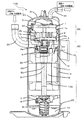
図1は、本発明の実施の形態に係る圧縮機100の断面構成の一例を示す縦断面図である。図1に基づいて、圧縮機100の構成及び動作について説明する。この圧縮機100は、回転式電動圧縮機であり、たとえば冷蔵庫や冷凍庫、自動販売機、空気調和器、冷凍装置、給湯器等の冷凍サイクル(ヒートポンプサイクル)の構成要素となるものである。なお、図1を含め、以下の図面では各構成部材の大きさの関係が実際のものとは異なる場合がある。
Hereinafter, embodiments of the present invention will be described with reference to the drawings.
FIG. 1 is a longitudinal sectional view showing an example of a sectional configuration of a
この圧縮機100は、冷媒を吸入し、圧縮して高温高圧の状態として吐出させるものである。圧縮機100は、一般的に、密閉型のケーシング内に、圧縮機構50と、圧縮機構50を駆動する駆動機構60とが収納されている。このケーシングは、アッパーシェル31、センターシェル30、及び、ロアシェル32で構成されており、圧力容器となっている。図1に示すように、圧縮機構50が上側に、駆動機構60が下側に、それぞれ配置されている。このケーシングの底部は、冷凍機油14を貯留する油だめとなっている。
The
圧縮機構50は、吸入パイプ33から吸入した冷媒を圧縮してケーシング内の上方に形成されている高圧室21に排出する機能を有している。この高圧室21に排出された冷媒は、吐出パイプ34から圧縮機100の外部に吐出されるようになっている。駆動機構60は、圧縮機構50で冷媒を圧縮するために、圧縮機構50を構成している揺動スクロール2を駆動する機能を果たすようになっている。つまり、駆動機構60がクランク軸6を介して揺動スクロール2を駆動することによって、圧縮機構50で冷媒を圧縮するようになっているのである。
The
圧縮機構50は、固定スクロール1と、揺動スクロール2と、フレーム4と、で概略構成されている。図1に示すように、揺動スクロール2は下側に、固定スクロール1は上側に配置されるようになっている。固定スクロール1は、台板1aと、台板1aの一方の面に立設された渦巻状突起である渦巻部1bと、で構成されている。揺動スクロール2は、台板2aと、台板2aの一方の面に立設された渦巻状突起である渦巻部2bと、で構成されている。固定スクロール1及び揺動スクロール2は、渦巻部1bと渦巻部2bとを互いに噛み合わせ、ケーシング内に装着されている。そして、渦巻部2bと渦巻部1bとの間には、相対的に容積が変化する圧縮室22が形成される。
The
固定スクロール1は、フレーム4に図示省略のボルト等によって固定されている。固定スクロール1の中央部には、圧縮され、高圧となった冷媒を吐出する吐出口3が形成されている。そして、圧縮され、高圧となった冷媒は、固定スクロール1の上部に設けられている高圧室21に排出されるようになっている。揺動スクロール2は、固定スクロール1に対して自転することなく公転運動を行うようになっている。また、揺動スクロール2の渦巻部2b形成面とは反対側の面(以下、スラスト面と称する)の略中心部には、中空円筒形状の偏心穴2cが形成されている。この偏心穴2cには、後述するクランク軸6の上端に設けられた偏心ピン部6aが嵌入(係合)されている。
The
フレーム4は、ケーシングの内周面に固着され、中心部にクランク軸6を貫通させるため貫通孔が形成されている。また、フレーム4には、揺動スクロール2のスラスト面側から軸方向下側に貫通する返油溝11aが形成されており、スラスト面を潤滑した冷凍機油14をケーシング底部に戻すようになっている。図1では、返油溝11aが1つだけ形成されている場合を例に示しているが、これに限定するものではない。たとえば、返油溝11aを2つ以上形成してもよい。なお、フレーム4は、その外周面を焼き嵌めや溶接等によってケーシングの内周面に固定するとよい。
The frame 4 is fixed to the inner peripheral surface of the casing, and a through hole is formed in the center portion for allowing the
駆動機構60は、電動機ステータ11の内周面側に回転可能に配設され、クランク軸6に固定された電動機ロータ10と、ケーシング内に垂直方向に収容され、固着保持された電動機ステータ11と、回転軸であるクランク軸6と、で概略構成されている。電動機ロータ10は、クランク軸6に固定され、電動機ステータ11への通電が開始することにより回転駆動し、クランク軸6を回転させるようになっている。この電動機ロータ10の下面には、以下で詳述するバランスウェイト10aが装着されている。電動機ステータ11は、たとえば固定子鉄心に複数相の固定子巻線を装着して構成するとよい。また、電動機ステータ11の外周面は焼き嵌め等によりケーシング(センターシェル30)に固着支持されている。すなわち、電動機ロータ10及び電動機ステータ11で電動機を構成している。
The
クランク軸6は、電動機ロータ10の回転に伴って回転し、揺動スクロール2を旋回させるようになっている。このクランク軸6は、上端をフレーム4の中心部に位置する主軸受5で、下端をセンターシェル30の下方に固定配置されたサブフレーム7の中心部に位置する副軸受8で、回転可能に支持されている。このクランク軸6の上端部は、揺動スクロール2の偏心穴2cと回転自在に嵌合する偏心ピン部6aが形成されている。また、クランク軸6の内部には、上端面まで連通している給油通路6bが形成されている。この給油通路6bは、ケーシング底部に貯留してある冷凍機油14の流路となるものである。
The
クランク軸6の下端側には、クランク軸6の回転に伴い冷凍機油14を汲み上げるオイルポンプ9が設けられている。このオイルポンプ9の遠心ポンプ作用により、冷凍機油14が汲み上げられ、給油通路6bを流れて圧縮機構50に供給されるようになっている。また、ケーシングを構成するセンターシェル30には、冷媒を吸入するための吸入パイプ33が連接されている。この吸入パイプ33は、シェル内空間(低圧室20)に開口するようになっている。さらに、ケーシングを構成するアッパーシェル31には、冷媒を吐出するための吐出パイプ34が連接されている。この吐出パイプ34は、シェル内空間(高圧室21)に開口するようになっている。
An oil pump 9 is provided at the lower end side of the
なお、揺動スクロール2と固定スクロール1との間には、揺動スクロール2の偏心旋回運動中における自転運動を阻止するための図示省略のオルダムリングが配設されている。このオルダムリングは、揺動スクロール2と固定スクロール1との間に配設され、揺動スクロール2の自転運動を阻止するとともに、公転運動を可能とする機能を果たすようになっている。つまり、オルダムリングは、揺動スクロール2の自転防止機構として機能している。また、圧縮機100には、電動機ステータ11に電源を供給するための密封端子13及びリード線12が設けられている。
Note that an Oldham ring (not shown) is provided between the orbiting
ここで、圧縮機100の動作について簡単に説明する。
密封端子13に通電すると、リード線12を介して電源が電動機ステータ11に供給される。電動機ロータ10は、電源が供給された電動機ステータ11が発生する回転磁界からの回転力(トルク)を受けて回転する。それに伴って、主軸受5と副軸受8に支持されているクランク軸6が回転駆動する。揺動スクロール2は、クランク軸6の偏心ピン部6aに係合されており、揺動スクロール2の自転運動がオルダムリングの自転防止機構によって公転運動に変換される。
Here, the operation of the
When the sealed
電動機ロータ10が回転するとき、電動機ロータ10の下面に装着されているバランスウェイト10aで揺動スクロール2の偏心公転運動に対するバランスを保っている。つまり、バランスウェイト10aは、電動機ロータ10とともに回転して、この回転に対しての質量バランスをとる機能を有している。その結果、クランク軸6の上部に偏心支持された揺動スクロール2が揺動されて公転旋回を始め、公知の圧縮原理により冷媒を圧縮する。まず、クランク軸6の回転駆動によって、ケーシング内の冷媒が固定スクロール1の渦巻部1bと揺動スクロール2の渦巻部2bとにより形成される圧縮室22内へ流れ、吸入過程が開始する。この吸入過程は、低圧冷媒ガスが、吸入パイプ33を介して外部から低圧室20内を介して圧縮室22内に吸い込まれることにより開始する。
When the
圧縮室22内に冷媒ガスが吸入されると、偏心させられた揺動スクロール2の公転旋回運動による固定スクロール1と揺動スクロール2との圧縮作用により、圧縮室22の容積を減少させる圧縮過程へと移行する。つまり、圧縮機構50では、揺動スクロール2が公転旋回運動すると、冷媒ガスが吸入口となる揺動スクロール2の渦巻部2b及び固定スクロール1の渦巻部1bの最外周開口部から取り込まれて、揺動スクロール2の回転とともに徐々に圧縮されながら中心部に向かうにようになっている。そして、圧縮室22で圧縮された冷媒ガスは、吐出過程に移行する。つまり、圧縮された高圧冷媒ガスは、固定スクロール1の吐出口3を通過し、高圧室21を経由してから吐出パイプ34を介して圧縮機100の外部へと吐出されるのである。
When the refrigerant gas is sucked into the
なお、低圧室20内の低圧冷媒ガスと高圧室21内の高圧冷媒ガスとは、固定スクロール1及びフレーム4により気密が保たれるように仕切られているのでケーシング内で混在することがない。また、クランク軸6が回転すると、オイルポンプ9の遠心ポンプ作用により冷凍機油14が吸引され、クランク軸6内に設けられた給油通路6bを通って主軸受5及び副軸受8等に供給された後、重力により返油溝11aを介して再びロアシェル32内へ戻る。そして、電動機ステータ11への通電を止めると、圧縮機100が運転を停止する。
Note that the low-pressure refrigerant gas in the low-
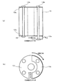
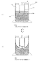
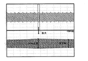
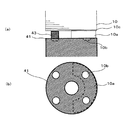
図2は、バランスウェイト10aと冷凍機油14との干渉を説明するための説明図である。図3は、圧縮機の運転中における渦の状態を説明するための説明図である。図4は、干渉が発生している場合における電流値の計測結果を示すグラフである。図2〜図4に基づいて、バランスウェイト10aと冷凍機油14との干渉によって圧縮効率が低減してしまう仕組みについて詳細に説明する。図2(a)が駆動機構60部分の縦断面図を、図2(b)が図2(a)のA−A断面図を、それぞれ示している。図3(a)が渦なしの状態を、図3(b)は渦ありの状態を、それぞれ示している。図4では、縦軸が電流値を、横軸が時間を、それぞれ表している。
FIG. 2 is an explanatory diagram for explaining the interference between the
図2(a)に示すように、バランスウェイト10aは、電動機ロータ10の底面の一部にリベット10bで固定されることで装着されるようになっている。また、バランスウェイト10aは、電動機ロータ10の底面における円形状の径と同程度の径を有した半リング状(図2(b)参照)の板金等を積層して構成されている。電動機ロータ10は、複数枚の電磁鋼板を積層させて構成されている。リベット10bは、軸方向に挿通されて各電磁鋼板を保持している。なお、電動機ロータ10の両端面には、端板10cが備えられ、端板10cを含めてリベット10bで保持されている。ここでは、4つのリベット10bで電動機ロータ10を保持し、そのうちの2つがバランスウェイト10aも固定している。ただし、リベット10bの個数を特に限定するものではない。
As shown in FIG. 2A, the
冷凍機油14は、運転中には圧縮機上部及び冷媒回路内を循環しているが、圧縮機100の運転停止等、冷媒回路内の圧力変化が起こった場合に圧縮機100内に戻ってくることがある。この返油によって、圧縮機100の底部に貯留される冷凍機油14が過多となってしまうことになる。冷凍機油14が過多となると、圧縮機100のケーシング内に固定される電動機ステータ11の側面に設けられた返油溝11aが冷凍機油14に浸かり、塞がってしまうことになる。つまり、冷凍機油14は、電動機ステータ11及び電動機ロータ10によって蓋をされた状態となり、オイルポンプ9による吸い上げか、又は電動機ステータ11及び電動機ロータ10間の微小な隙間から流れ落ちるか、以外の行き場をなくし、自由度を失ってしまう(図3(a)参照)。
The
図2に示すように、冷媒や自由度の低下した冷凍機油14が電動機ロータ10底部においてバランスウェイト10aの回転抵抗になる。つまり、冷凍機油14から受ける電動機ロータ10底部に固定されたバランスウェイト10aへの流体力が大きくなり、運転に必要な一定出力に達するためのトルク及び電流値が共に上昇し、圧縮機100の能力低下に繋がることになる。また、電動機ロータ10が回転運動をすると、バランスウェイト10aの周囲でガス冷媒や冷凍機油14の流れが大きく乱れ、電動機ロータ10の回転動力の損失が起こる。加えて、冷凍機油14が過多となり、自由度を失っている状態で、電動機ロータ10が回転運動をすると、より大きな損失が生じることになる。つまり、撹拌損失が増大することにより、圧縮機100の全体の運転効率が低下してしまうのである。
As shown in FIG. 2, the refrigerant and the refrigerating
この損失は、常に一定値で保たれるわけではない。冷凍機油14には、電動機ロータ10の回転運動によりバランスウェイト10a、クランク軸6、及び、副軸受8から回転力を与えられ、クランク軸6を中心とした渦が発生する(図3(b)参照)。この渦により、冷凍機油14が与えるバランスウェイト10aへの流体力の変動が生じ、電流値の変動(揺れ)が起こるため(図4参照)、圧縮機100の能力が安定せず、圧縮機100から発生する騒音が大きくなり、保護装置が作動してしまう等の安定した運転が継続できないという問題も生じる。つまり、圧縮機100の能力を安定的に維持させるためには、図4に示す電流値の変動を少なくさせる必要があるのである。
This loss is not always kept constant. The refrigerating
そこで、圧縮機100では、バランスウェイト保護部材(以下に説明するバランスウェイト保護部材40〜42)を設けて、電流値の変動を低減させている。このバランスウェイト保護部材は、バランスウェイト10aによって冷凍機油14が攪拌されてしまうことを抑止するためのものである。すなわち、バランスウェイト保護部材は、電動機ロータ10(詳しくはバランスウェイト10a)と冷凍機油14との干渉を防止するためのものである。このようなバランスウェイト保護部材を設けることで、自由度が低下した冷凍機油14が存在しても、冷凍機油14に渦を発生させることがなく、渦の形成と破砕の繰り返しによる流体力の変動による影響を低減することができる。
Therefore, in the
バランスウェイト保護部材を設けた圧縮機100の効果としては、バランスウェイト保護部材を設けていない圧縮機では図4に示すように電流値の上昇率が30%であるのに対し、以下に説明するバランスウェイト保護部材40を設けた圧縮機100では電流値の上昇率が10%、以下に説明するバランスウェイト保護部材41及びバランスウェイト保護部材42を設けた圧縮機100では電流値の上昇率が20%であることが確認されている。
The effect of the
また、バランスウェイト保護部材は、電動機ロータ10の回転中心でほぼ点対称な形状としている、圧縮機100内の重量バランスを調節するバランスウェイト10aの形状・重量に与える影響が小さく、コストアップも抑えられる。さらに、他の部材に与える影響が小さいという点で、現在既に量産されている機種の高性能化のアイテムとしての追加搭載も容易である。加えて、バランスウェイト10aと別部材であるため、板金加工による成型が容易である。以上のように、バランスウェイト保護部材は、必要最小限にコストアップを抑え、かつ、安定した高い性能の電動機を得ることができる。したがって、信頼性が高く、製造に要する手間及びコストを低減した圧縮機100の提供が実現できる。
In addition, the balance weight protection member has a substantially point-symmetric shape at the rotation center of the
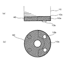
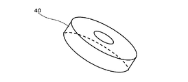
図5は、バランスウェイト保護部材の一例(以下、バランスウェイト保護部材40と称する)を説明するための説明図である。図6は、バランスウェイト保護部材40の全体形状を示す斜視図である。図5及び図6に基づいて、実施の形態の特徴事項であるバランスウェイト保護部材40について詳細に説明する。図5(a)が電動機ロータ10の断面構成の一部を拡大して示す縦断面図であり、図5(b)が電動機ロータ10を下から見た状態を示す平面図である。上述したように、電動機は、電動機ステータ11、及び、その中央にクランク軸6に焼嵌られた電動機ロータ10と、で構成されている。そして、電動機ロータ10の底部には、バランスウェイト10aが装着されている。
FIG. 5 is an explanatory diagram for explaining an example of a balance weight protection member (hereinafter referred to as a balance weight protection member 40). FIG. 6 is a perspective view showing the overall shape of the balance
図5に示すように、バランスウェイト10aは、バランスウェイト保護部材40によって全体を覆われて電動機ロータ10の底部に装着されている。このバランスウェイト保護部材40は、バランスウェイト10aが内部に収納されるように中空状になっており、中心が貫通された円筒形状で構成されている。バランスウェイト保護部材40の軸方向の長さ(高さ)を、バランスウェイト10aの軸方向の長さ(厚み)と同程度にし、バランスウェイト10aのみを覆う形態とすることが望ましい。また、バランスウェイト保護部材40の横断面における円形状の径は、電動機ロータ10の底面円形状の径と同程度としている。
As shown in FIG. 5, the
ただし、バランスウェイト保護部材40の軸方向の長さを、バランスウェイト10aの軸方向の長さよりも長く、電動機ロータ10の底面に設けた端板10c及び電動機ロータ10を構成する下方の電磁鋼板を覆う形態してもよい。このような形態でバランスウェイト保護部材40を構成する場合は、電動機ロータ10と電動機ステータ11と間に設けるエアギャップよりも薄肉の部材でバランスウェイト保護部材40を形成すればよい。すなわち、バランスウェイト保護部材40は、電動機ロータ10の回転運動の妨害にならない形態であればよいのである。したがって、バランスウェイト保護部材40は、電磁鋼板を覆いマグネットの磁束の乱れ、短絡が生じることによる性能低下がない形態にすることが望ましい。
However, the axial length of the balance
また、バランスウェイト保護部材40の軸方向の長さを、バランスウェイト10aの軸方向の長さよりも短くすると、バランスウェイト保護部材40からはみ出すバランスウェイト10aと冷媒及び冷凍機油14との間で干渉が起こり、圧縮機100の運転効率が低下してしまうことになることは言うまでもない。バランスウェイト保護部材40の軸方向の長さを、バランスウェイト10aの軸方向の長さよりも短くする形態とするには、以下で説明するような更なる工夫が必要になる。
Further, when the axial length of the balance
図7は、バランスウェイト保護部材の他の一例(以下、バランスウェイト保護部材41と称する)を説明するための説明図である。図8は、バランスウェイト保護部材41の全体形状を示す斜視図である。図7及び図8に基づいて、実施の形態の特徴事項であるバランスウェイト保護部材41について、バランスウェイト保護部材40との相違点を中心として詳細に説明する。図7(a)が電動機ロータ10の断面構成の一部を拡大して示す縦断面図であり、図7(b)が電動機ロータ10を下から見た状態を示す平面図である。
FIG. 7 is an explanatory diagram for explaining another example of the balance weight protection member (hereinafter referred to as a balance weight protection member 41). FIG. 8 is a perspective view showing the overall shape of the balance
バランスウェイト保護部材41は、電動機ロータ10の底面に設けた端板10cとバランスウェイト10aとでバランスウェイト保護部材41の一部を挟持し、固定するように構成されている。もしくは、バランスウェイト保護部材41は、バランスウェイト保護部材41を電動機ロータ10の底面側の端板10cとして兼用させるように構成されている。バランスウェイト保護部材41の軸方向の長さをバランスウェイト10aの軸方向の長さ以上で、かつ、バランスウェイト保護部材41の直径を端板10cの直径以下に形成することが望ましい。また、バランスウェイト保護部材41は、バランスウェイト10aを囲い込むように中空状になっており、中心が貫通された円筒形状で構成されており、下端面が開口されている。
The balance
ただし、バランスウェイト保護部材41の直径を、端板10cの直径以上としてもよい。このような形態でバランスウェイト保護部材41を構成する場合は、電動機ロータ10の直径からはみ出す形状となるので、電動機ステータ11と接触し、故障の原因となる可能性があることに留意する必要がある。バランスウェイト保護部材41は、バランスウェイト10a全体を囲い込み、冷凍機油14との間の障壁として機能させることで、冷凍機油14との干渉を防いでいる。バランスウェイト保護部材41は、取り付け方法、及び、加工性を考慮して下端面を開口させている。このことによって、バランスウェイト保護部材41の軸方向からの冷凍機油14の侵入を防ぐために、バランスウェイト保護部材41の軸方向の長さをバランスウェイト10aの軸方向の長さ以上としておくとよい。
However, the diameter of the balance
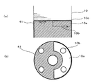
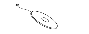
図9は、バランスウェイト保護部材の他の一例(以下、バランスウェイト保護部材42と称する)を説明するための説明図である。図10は、バランスウェイト保護部材42の全体形状を示す斜視図である。図9及び図10に基づいて、実施の形態の特徴事項であるバランスウェイト保護部材42について、バランスウェイト保護部材40及びバランスウェイト保護部材41との相違点を中心として詳細に説明する。図9(a)が電動機ロータ10の断面構成の一部を拡大して示す縦断面図であり、図9(b)が電動機ロータ10を下から見た状態を示す平面図である。
FIG. 9 is an explanatory diagram for explaining another example of the balance weight protection member (hereinafter referred to as a balance weight protection member 42). FIG. 10 is a perspective view showing the overall shape of the balance
バランスウェイト保護部材42は、リング状の平板形状として構成されている。このバランスウェイト保護部材42は、バランスウェイト10aの下端面に固定されるようになっている。バランスウェイト保護部材42の直径は、バランスウェイト10aの直径以上、かつ、端板10cの直径以下に形成することが望ましい。ただし、バランスウェイト保護部材42の直径を、端板10cの直径以上としてもよい。このような形態でバランスウェイト保護部材42を構成する場合は、電動機ロータ10の直径からはみ出す形状となるので、電動機ステータ11と接触し、故障の原因となる可能性があることに留意する必要がある。
The balance
また、バランスウェイト保護部材42は、図9(a)に示すように、バランスウェイト10aと同程度の高さを有した支持部材43でバランスウェイト10aが設けられていない側が支持されている。バランスウェイト保護部材42は、バランスウェイト10aの下面に設けられ、バランスウェイト10aと冷凍機油14との間の障壁として機能させることで、バランスウェイト10aと冷凍機油14との干渉を防いでいる。なお、支持部材43の形状や大きさ、材質、個数等を特に限定するものではない。
Further, as shown in FIG. 9A, the balance
図11は、バランスウェイト保護部材41の他の設置例を説明するための説明図である。図11に基づいて、バランスウェイト保護部材41の他の設置例について説明する。図11(a)が電動機ロータ10の断面構成の一部を拡大して示す縦断面図であり、図11(b)が電動機ロータ10を下から見た状態を示す平面図である。図7及び図8で示したように、バランスウェイト保護部材41は、バランスウェイト10aを囲い込むように中空状になっており、中心が貫通された円筒形状で構成されており、下端面が開口されている。
FIG. 11 is an explanatory diagram for explaining another installation example of the balance
このように構成されたバランスウェイト保護部材41を、図11ではバランスウェイト10aの下端面に固定している。このようにバランスウェイト保護部材41を設置すれば、バランスウェイト保護部材41がバランスウェイト10aと冷凍機油14との間の障壁として機能させることができ、バランスウェイト10aと冷凍機油14との干渉を防止することができる。
The balance
ここで、バランスウェイト保護部材の取り付け方法の例について簡単に説明する。
第一に、バランスウェイト保護部材を、電動機ロータ10の組立の際に同時に複数のリベット10b等で固定して取り付ける方法がある。ただし、バランスウェイト保護部材のうちバランスウェイト10aの下面に取り付け面を持つもの(図5、図9及び図11で示したバランスウェイト保護部材)については、バランスウェイト10a下端面でのみ固定することも可能であるが、それでは端板10cとの間にバランスウェイト高さ分の隙間ができてしまい、十分に固定できずに歪んでしまうことになる。
Here, the example of the attachment method of a balance weight protection member is demonstrated easily.
First, there is a method in which the balance weight protection member is fixed and attached with a plurality of
この対策としては、バランスウェイト10aによる支持がない固定位置には、バランスウェイト保護部材を支持するためのバランスウェイト10aと同じ高さ(バランスウェイト10aの軸方向の長さ)の部材(上述した支持部材43)を設けることが考えられる。支持部材43としては、たとえばパイプ状の部材を用いることができる。この支持部材43は、端板10cとは別体の単体として構成したものでもよく、端板10cもしくはバランスウェイト10aと一体型として構成したものでもよい。
As a countermeasure against this, in a fixed position where the
第二に、バランスウェイト保護部材のうちバランスウェイト10aの下面に取り付け面を持つもの(図5、図9及び図11で示したバランスウェイト保護部材)については、バランスウェイト10aもしくはリベット10b端部にネジ穴を有する形態とし、ネジ等の締結部材を用いてネジ止めで締結固定する方法がある。なお、締結部材の種類や本数については、圧縮機100に搭載する電動機が運転中に加えられるトルク(たとえば、電動機ロータ10との回転トルクや、冷凍機油14及び冷媒との粘性抵抗、慣性力、遠心力)以上の軸力を有するように選定することが条件となる。また、締結部材の緩みを防ぐために、たとえばロックタイトのような冷凍機油14及び冷媒中でも有効な接着剤やシールテープをネジ止めの際に用いる方法も有効である。
Secondly, the balance weight protection member having a mounting surface on the lower surface of the
第三に、バランスウェイト保護部材を他部材(たとえば、端板10cやバランスウェイト10a)と接する位置で溶接固定して取り付ける方法がある。このような方法でバランスウェイト保護部材を取り付けると、部品点数が増えないという点でメリットを有する。ただし、熱ひずみによる電磁的特性の低下やマグネットの磁力の低下といった問題を十分考慮し、電動機ロータ10が有する性能と構造に影響を与えないように取り付けることが条件である。
Third, there is a method in which the balance weight protection member is attached by welding and fixing at a position in contact with another member (for example, the
次に、バランスウェイト保護部材の材質の選定方法の例について簡単に説明する。ここでは、電動機ロータ10を構成している電磁鋼板、端板10c、及び、バランスウェイト10aを複数のリベット10b等で固定することで構成されている電動機ロータ10に取り付けるバランスウェイト保護部材の材質の選定方法について説明する。
Next, an example of a method for selecting the material of the balance weight protection member will be briefly described. Here, the material of the balance weight protection member attached to the
第一に、バランスウェイト保護部材は、たとえば板金のプレス加工による成型が可能な材質で構成することが望ましい。このような材質でバランスウェイト保護部材を構成すれば、簡易な製造工程で構成することができるだけでなく、これによりコストやバランス量の変化を抑えることができる。すなわち、バランスウェイト保護部材の製造に要する手間及び費用を低減することができるのである。 First, it is desirable that the balance weight protection member is made of a material that can be molded by pressing a sheet metal, for example. If the balance weight protection member is made of such a material, it can be constituted not only by a simple manufacturing process, but also changes in cost and balance amount can be suppressed. That is, it is possible to reduce the labor and cost required for manufacturing the balance weight protection member.
第二に、バランスウェイト保護部材は、電動機ロータ10の回転運動に伴って加えられる力や、遠心力、冷凍機油14等との干渉による摩擦抵抗に耐え得る以上の強度を有し、かつ、バランスウェイト10aの形状に合わせた加工性を有する材質で構成することが望ましい。このような材質でバランスウェイト保護部材を構成すれば、製造に要する手間を低減できるだけでなく、圧縮機100の性能を安定して維持することができる。
Secondly, the balance weight protection member has a strength that can withstand the force applied with the rotational movement of the
第三に、バランスウェイト保護部材は、非磁性体の材質で構成することもできる。このような材質でバランスウェイト保護部材を構成すれば、電動機ロータ10内に収納されている永久磁石の磁束の軸方向への短絡を抑止することができ、より高い性能を維持できることになる。以上説明したような材質の中から、圧縮機100の適用条件を考慮した上で適宜選定して、バランスウェイト保護部材を構成するとよい。
Thirdly, the balance weight protection member can be made of a non-magnetic material. If the balance weight protection member is made of such a material, a short circuit in the axial direction of the magnetic flux of the permanent magnet housed in the
なお、上述した実施の形態では、バランスウェイト保護部材を、冷凍機油14中でのバランスウェイト10aの回転運動において利用する場合を例に説明したが、その他の流体(たとえば、冷媒)中での運転にも利用できることは言うまでもない。
In the above-described embodiment, the balance weight protecting member is used as an example in the rotational motion of the
1 固定スクロール、1a 台板、1b 渦巻部、2 揺動スクロール、2a 台板、2b 渦巻部、2c 偏心穴、3 吐出口、4 フレーム、5 主軸受、6 クランク軸、6a 偏心ピン部、6b 給油通路、7 サブフレーム、8 副軸受、9 オイルポンプ、10 電動機ロータ、10a バランスウェイト、10b リベット、10c 端板、11 電動機ステータ、11a 返油溝、12 リード線、13 密封端子、14 冷凍機油、20 低圧室、21 高圧室、22 圧縮室、30 センターシェル、31 アッパーシェル、32 ロアシェル、33 吸入パイプ、34 吐出パイプ、40 バランスウェイト保護部材、41 バランスウェイト保護部材、42 バランスウェイト保護部材、43 支持部材、50 圧縮機構、60 駆動機構、100 圧縮機。
1 fixed scroll, 1a base plate, 1b spiral part, 2 swing scroll, 2a base plate, 2b spiral part, 2c eccentric hole, 3 discharge port, 4 frame, 5 main bearing, 6 crankshaft, 6a eccentric pin part, 6b Oil supply passage, 7 subframe, 8 sub bearing, 9 oil pump, 10 motor rotor, 10a balance weight, 10b rivet, 10c end plate, 11 motor stator, 11a oil return groove, 12 lead wire, 13 sealing terminal, 14
Claims (7)
前記ケーシング内に垂直方向に収容される電動機ステータと、
前記電動機ステータの内周面側に回転可能に配設した電動機ロータと、
前記電動機ロータの中心部に挿入され、前記電動機ロータとともに回転駆動するクランク軸と、
前記電動機ロータの底部に取り付けられ、前記電動機ロータとともに回転するバランスウェイトと、
前記バランスウェイトの少なくとも底部に取り付けられて、前記バランスウェイトによる前記ケーシング内の流体との干渉を防止するためのバランスウェイト保護部材と、を有している
ことを特徴とする圧縮機。 A casing,
An electric motor stator housed vertically in the casing;
An electric motor rotor rotatably disposed on the inner peripheral surface side of the electric motor stator;
A crankshaft inserted into the center of the electric motor rotor and driven to rotate together with the electric motor rotor;
A balance weight attached to the bottom of the motor rotor and rotating together with the motor rotor;
A compressor comprising: a balance weight protection member attached to at least a bottom portion of the balance weight and preventing interference with the fluid in the casing by the balance weight.
前記電動機ロータの底面円形状と同程度の径を有している
ことを特徴とする請求項1に記載の圧縮機。 The balance weight protection member is
The compressor according to claim 1, wherein the compressor has a diameter approximately equal to a circular shape of a bottom surface of the motor rotor.
中空円柱形状あるいは円盤形状に構成されている
ことを特徴とする請求項2に記載の圧縮機。 The balance weight protection member is
The compressor according to claim 2, wherein the compressor is configured in a hollow cylindrical shape or a disk shape.
前記バランスウェイト保護部の軸方向の長さを、前記バランスウェイトの軸方向の長さ以上とすることで、前記バランスウェイト保護部材で前記バランスウェイト全体を覆うようにしている
ことを特徴とする請求項3に記載の圧縮機。 In the balance weight protection member configured in a hollow cylindrical shape,
The balance weight protection member covers the entire balance weight by setting the axial length of the balance weight protection portion to be equal to or greater than the axial length of the balance weight. Item 4. The compressor according to Item 3.
ことを特徴とする請求項4に記載の圧縮機。 The compressor according to claim 4, wherein a lower end surface of the balance weight protection member is opened.
前記バランスウェイト保護部材で前記バランスウェイトの下面側を覆うようにしている
ことを特徴とする請求項3に記載の圧縮機。 In the balance weight protection member configured in a hollow cylindrical shape or a disk shape,
The compressor according to claim 3, wherein the balance weight protecting member covers a lower surface side of the balance weight.
前記バランスウェイトの軸方向の長さと同程度の長さを有した支持部材を前記電動機ロータの底部の前記バランスウェイトが設けられていない位置に設け、
前記バランスウェイト保護部材は、
前記バランスウェイトと前記支持部材で支持されている
ことを特徴とする請求項6に記載の圧縮機。 Providing the balance weight on a part of the bottom of the motor rotor;
A support member having a length approximately the same as the axial length of the balance weight is provided at a position where the balance weight is not provided at the bottom of the motor rotor,
The balance weight protection member is
The compressor according to claim 6, wherein the compressor is supported by the balance weight and the support member.
Priority Applications (1)
| Application Number | Priority Date | Filing Date | Title |
|---|---|---|---|
| JP2008319557A JP2010144528A (en) | 2008-12-16 | 2008-12-16 | Compressor |
Applications Claiming Priority (1)
| Application Number | Priority Date | Filing Date | Title |
|---|---|---|---|
| JP2008319557A JP2010144528A (en) | 2008-12-16 | 2008-12-16 | Compressor |
Publications (1)
| Publication Number | Publication Date |
|---|---|
| JP2010144528A true JP2010144528A (en) | 2010-07-01 |
Family
ID=42565222
Family Applications (1)
| Application Number | Title | Priority Date | Filing Date |
|---|---|---|---|
| JP2008319557A Withdrawn JP2010144528A (en) | 2008-12-16 | 2008-12-16 | Compressor |
Country Status (1)
| Country | Link |
|---|---|
| JP (1) | JP2010144528A (en) |
Cited By (5)
| Publication number | Priority date | Publication date | Assignee | Title |
|---|---|---|---|---|
| WO2014049914A1 (en) * | 2012-09-28 | 2014-04-03 | ダイキン工業株式会社 | Rotary compressor |
| WO2016120982A1 (en) * | 2015-01-26 | 2016-08-04 | 三菱電機株式会社 | Electrically driven compressor |
| KR102281348B1 (en) * | 2020-01-31 | 2021-07-23 | 엘지전자 주식회사 | A compressor |
| CN114060465A (en) * | 2020-07-31 | 2022-02-18 | 上海海立电器有限公司 | Compressor and damper thereof |
| WO2023176154A1 (en) * | 2022-03-17 | 2023-09-21 | 株式会社豊田自動織機 | Double rotary type scroll compressor |
-
2008
- 2008-12-16 JP JP2008319557A patent/JP2010144528A/en not_active Withdrawn
Cited By (11)
| Publication number | Priority date | Publication date | Assignee | Title |
|---|---|---|---|---|
| WO2014049914A1 (en) * | 2012-09-28 | 2014-04-03 | ダイキン工業株式会社 | Rotary compressor |
| JP2014070585A (en) * | 2012-09-28 | 2014-04-21 | Daikin Ind Ltd | Rotary compressor |
| CN104641115A (en) * | 2012-09-28 | 2015-05-20 | 大金工业株式会社 | Rotary compressor |
| EP2905470A4 (en) * | 2012-09-28 | 2016-08-03 | Daikin Ind Ltd | ROTARY COMPRESSOR |
| CN104641115B (en) * | 2012-09-28 | 2017-02-08 | 大金工业株式会社 | Rotary compressor |
| US9748815B2 (en) | 2012-09-28 | 2017-08-29 | Daikin Industries, Ltd. | Rotary compressor with the balance weight formed with a recess for receiving the head of a rivet |
| WO2016120982A1 (en) * | 2015-01-26 | 2016-08-04 | 三菱電機株式会社 | Electrically driven compressor |
| JPWO2016120982A1 (en) * | 2015-01-26 | 2017-06-15 | 三菱電機株式会社 | Electric compressor |
| KR102281348B1 (en) * | 2020-01-31 | 2021-07-23 | 엘지전자 주식회사 | A compressor |
| CN114060465A (en) * | 2020-07-31 | 2022-02-18 | 上海海立电器有限公司 | Compressor and damper thereof |
| WO2023176154A1 (en) * | 2022-03-17 | 2023-09-21 | 株式会社豊田自動織機 | Double rotary type scroll compressor |
Similar Documents
| Publication | Publication Date | Title |
|---|---|---|
| US8992188B2 (en) | Revolution type compressor | |
| JP4841536B2 (en) | Motor and refrigerant compressor provided with the same | |
| JP4874628B2 (en) | Oil discharge prevention device for scroll compressor | |
| EP2390507B1 (en) | Shaft bearing clearances for an hermetic compressor | |
| CN204327493U (en) | Scroll compressor | |
| JP2018040261A (en) | Refrigerant compressor | |
| JP2010144528A (en) | Compressor | |
| JP2009131026A (en) | Electric motor and refrigerant compressor equipped with the same | |
| JP2012207624A (en) | Scroll compressor | |
| JP2014132158A (en) | Scroll compressor | |
| JP6745913B2 (en) | Compressor | |
| JP6723027B2 (en) | Electric compressor | |
| JP6808044B2 (en) | Scroll compressor | |
| JP6320575B2 (en) | Electric compressor | |
| JP6383381B2 (en) | Compressor | |
| JP2020041476A (en) | Compressor | |
| JP2014136985A (en) | Scroll type compressor | |
| JP5075733B2 (en) | Scroll compressor | |
| JP5836845B2 (en) | Scroll compressor | |
| JP2016156297A (en) | Scroll compressor | |
| JP6598881B2 (en) | Scroll compressor | |
| JP5559839B2 (en) | Hermetic scroll compressor | |
| WO2025100044A1 (en) | Scroll compressor | |
| WO2018212076A1 (en) | Scroll compressor | |
| JP6627557B2 (en) | Bearing housing and rotating machine |
Legal Events
| Date | Code | Title | Description |
|---|---|---|---|
| A300 | Withdrawal of application because of no request for examination |
Free format text: JAPANESE INTERMEDIATE CODE: A300 Effective date: 20120306 |