JP2010143694A - Document feeding apparatus - Google Patents
Document feeding apparatus Download PDFInfo
- Publication number
- JP2010143694A JP2010143694A JP2008321630A JP2008321630A JP2010143694A JP 2010143694 A JP2010143694 A JP 2010143694A JP 2008321630 A JP2008321630 A JP 2008321630A JP 2008321630 A JP2008321630 A JP 2008321630A JP 2010143694 A JP2010143694 A JP 2010143694A
- Authority
- JP
- Japan
- Prior art keywords
- document
- tray
- feeding
- document tray
- cpu
- Prior art date
- Legal status (The legal status is an assumption and is not a legal conclusion. Google has not performed a legal analysis and makes no representation as to the accuracy of the status listed.)
- Pending
Links
Images
Classifications
-
- B—PERFORMING OPERATIONS; TRANSPORTING
- B65—CONVEYING; PACKING; STORING; HANDLING THIN OR FILAMENTARY MATERIAL
- B65H—HANDLING THIN OR FILAMENTARY MATERIAL, e.g. SHEETS, WEBS, CABLES
- B65H3/00—Separating articles from piles
- B65H3/02—Separating articles from piles using friction forces between articles and separator
- B65H3/06—Rollers or like rotary separators
- B65H3/0607—Rollers or like rotary separators cooperating with means for automatically separating the pile from roller or rotary separator after a separation step
-
- B—PERFORMING OPERATIONS; TRANSPORTING
- B65—CONVEYING; PACKING; STORING; HANDLING THIN OR FILAMENTARY MATERIAL
- B65H—HANDLING THIN OR FILAMENTARY MATERIAL, e.g. SHEETS, WEBS, CABLES
- B65H2511/00—Dimensions; Position; Numbers; Identification; Occurrences
- B65H2511/20—Location in space
-
- B—PERFORMING OPERATIONS; TRANSPORTING
- B65—CONVEYING; PACKING; STORING; HANDLING THIN OR FILAMENTARY MATERIAL
- B65H—HANDLING THIN OR FILAMENTARY MATERIAL, e.g. SHEETS, WEBS, CABLES
- B65H2511/00—Dimensions; Position; Numbers; Identification; Occurrences
- B65H2511/40—Identification
- B65H2511/414—Identification of mode of operation
-
- B—PERFORMING OPERATIONS; TRANSPORTING
- B65—CONVEYING; PACKING; STORING; HANDLING THIN OR FILAMENTARY MATERIAL
- B65H—HANDLING THIN OR FILAMENTARY MATERIAL, e.g. SHEETS, WEBS, CABLES
- B65H2513/00—Dynamic entities; Timing aspects
- B65H2513/50—Timing
- B65H2513/512—Starting; Stopping
-
- B—PERFORMING OPERATIONS; TRANSPORTING
- B65—CONVEYING; PACKING; STORING; HANDLING THIN OR FILAMENTARY MATERIAL
- B65H—HANDLING THIN OR FILAMENTARY MATERIAL, e.g. SHEETS, WEBS, CABLES
- B65H2551/00—Means for control to be used by operator; User interfaces
- B65H2551/10—Command input means
-
- B—PERFORMING OPERATIONS; TRANSPORTING
- B65—CONVEYING; PACKING; STORING; HANDLING THIN OR FILAMENTARY MATERIAL
- B65H—HANDLING THIN OR FILAMENTARY MATERIAL, e.g. SHEETS, WEBS, CABLES
- B65H2801/00—Application field
- B65H2801/03—Image reproduction devices
- B65H2801/06—Office-type machines, e.g. photocopiers
Landscapes
- Engineering & Computer Science (AREA)
- Mechanical Engineering (AREA)
- Facsimiles In General (AREA)
- Sheets, Magazines, And Separation Thereof (AREA)
Abstract
【課題】 原稿トレイが給送位置まで上昇して原稿を給送する原稿給送装置において、載置する原稿の枚数が少ない場合でも、原稿給送開始までの時間を短縮する。
【解決手段】 原稿トレイ30に原稿が載置されている状態で、スタートキー406やスタートキー以外のキーの何れの押下にも応答して原稿トレイ30の上昇を開始する。更に、スタートキー406の押下に応答して原稿トレイ30を上昇させる第1モードと、スタートキー以外のキーの押下にも応答して原稿トレイ30を上昇させる第2モードの何れかを選択可能である。
【選択図】 図6PROBLEM TO BE SOLVED: To shorten a time required for starting document feeding even in a document feeding device for feeding a document by raising a document tray to a feeding position even when the number of documents to be placed is small.
In a state where a document is placed on the document tray 30, the document tray 30 starts to rise in response to pressing of any key other than the start key 406 and the start key. Furthermore, it is possible to select either the first mode in which the document tray 30 is raised in response to pressing of the start key 406 or the second mode in which the document tray 30 is raised in response to pressing of a key other than the start key. is there.
[Selection] Figure 6
Description
本発明は、昇降する原稿トレイを有する原稿給紙装置に関するものである。 The present invention relates to a document feeder having a document tray that moves up and down.
近年、原稿の画像情報をデジタルデータに変換し、プリンタ等の画像形成装置やネットワークに接続されたコンピュータ等のストレージデバイスに出力する画像読取装置が広く用いられている。最近では、大量の原稿を早く読み取ることや、さらに、FCOT(First Copy Output Time)すなわち、コピーの開始を指示してから1枚目が出力されるまでの時間が早い装置がスペックとして重要視される傾向も出てきている。それにともない、原稿給送装置の原稿トレイに一度にセットできる原稿の量を増やすことも求められている。そこで、原稿トレイをリフタ機構により昇降させることで、大量の原稿でも少量の原稿でも対応できるような原稿トレイをもつ自動原稿給紙装置が必要とされてきている。 2. Description of the Related Art In recent years, image reading apparatuses that convert document image information into digital data and output the image data to an image forming apparatus such as a printer or a storage device such as a computer connected to a network are widely used. Recently, an apparatus that reads a large amount of documents quickly, and has a fast time from when a copy start instruction is issued to the first copy output is emphasized as specifications. There is also an increasing trend. Accordingly, it is also required to increase the amount of documents that can be set on the document tray of the document feeder. Therefore, there is a need for an automatic document feeder having a document tray that can handle a large amount of documents or a small amount of documents by moving the document tray up and down by a lifter mechanism.
特許文献1には、原稿トレイが昇降機構をもつ自動原稿給紙装置で、第1モードでは原稿がセットされたことを検知したことに応答して、自動的に原稿トレイを上昇させ、第2モードは給紙開始信号受信後に原稿トレイを上昇させることが記載されている。 In Patent Document 1, an automatic document feeder having an elevating mechanism for a document tray, and in response to detecting that a document is set in the first mode, the document tray is automatically raised, The mode describes that the document tray is raised after receiving a paper feed start signal.
また、特許文献2には、原稿トレイが昇降機構をもつ自動原稿給紙装置で、原稿給紙開始時に原稿トレイを上昇させてから給紙を開始し順次原稿を給送し、原稿トレイ内の最終原稿の給送が終了した時点で原稿トレイを下降させることが記載されている。
しかしながら、特許文献1の第1モードでは、原稿が原稿トレイにセットされたことを検知するとすぐに自動で原稿トレイが上昇することになる。しかし、大量の原稿を小分けにして原稿トレイにセットする際、小分けにした1つの原稿束をセットしている最中に原稿トレイが上昇してしまう。しかし、原稿トレイが上昇中にユーザが原稿をセットするような動きになるため、すべての原稿を原稿トレイにセットする前に、原稿トレイが給紙開始可能意位置まで上昇してしまい、ユーザがすべての原稿をセットできないという不具合が発生する可能性がある。また、原稿トレイが上昇中に強引に原稿をセットする場合には、原稿をセットする空間が徐々に狭くなっていくところに原稿をセットすることになるので、原稿を適切にセットすることができない可能性がある。その結果、原稿が折れたり、原稿セット完了後に給紙を開始しても原稿給紙不良が発生して紙詰まりが発生したりする可能性がある。 However, in the first mode of Patent Document 1, the document tray is automatically raised as soon as it is detected that the document is set on the document tray. However, when a large amount of originals are divided into small pieces and set on the original tray, the original tray rises while one subdivided original bundle is being set. However, since the user moves the document tray while the document tray is raised, the document tray is raised to a position where the feeding can be started before setting all the documents on the document tray. There is a possibility that all the originals cannot be set. In addition, when a document is forcibly set while the document tray is raised, the document cannot be set properly because the document is set where the space for setting the document is gradually narrowed. there is a possibility. As a result, there is a possibility that the document is folded, or even if the feeding is started after the document setting is completed, a document feeding failure occurs and a paper jam occurs.
また、特許文献1の第1モード及び特許文献2では、読取開始の指示の入力後に、原稿トレイを給紙可能な位置まで上昇させて順次原稿搬送路へ原稿を搬送させている。従って、ユーザが原稿トレイに原稿セットするミスオペレーションになることはほとんどないが、原稿トレイにセットする原稿が少ない場合には、原稿トレイの上昇する量が多くなり、原稿を給紙開始可能になるまでの時間が長くなってしまう。
In the first mode of Patent Document 1 and
上記の課題を解決するために、本発明の原稿給送装置は、原稿を積載するための原稿トレイと、前記原稿トレイに原稿が載置されたことを検出する原稿検知センサと、前記原稿トレイを、原稿積載を待機する待機位置と原稿給送が可能な給送位置との間で上昇及び下降させる駆動手段と、前記原稿トレイが前記給送位置にあるときに、原稿の給送を行う給送手段と、原稿の給送を伴う処理の開始を指示するスタートキーと、前記処理の条件を設定するための操作キーと、前記原稿トレイに原稿が載置されていることが前記原稿検知センサにより検出されている状態で、前記スタートキーと前記操作キーの何れの押下にも応答して前記原稿トレイを上昇させる制御手段と、
を有することを特徴とする。
In order to solve the above-described problems, the document feeder of the present invention includes a document tray for stacking documents, a document detection sensor for detecting that a document is placed on the document tray, and the document tray. Driving means for raising and lowering between a standby position for waiting for document stacking and a feed position where document feeding is possible, and feeding a document when the document tray is at the feeding position The document detection means that a document is placed on the document tray, a start key for instructing the start of processing involving document feeding, an operation key for setting the processing condition, and the document tray. Control means for raising the document tray in response to pressing of either the start key or the operation key while being detected by a sensor;
It is characterized by having.
また、本発明の原稿給送装置は、原稿を積載するための原稿トレイと、前記原稿トレイに原稿が載置されたことを検出する原稿検知センサと、前記原稿トレイを、原稿積載を待機する待機位置と原稿給送が可能な給送位置との間で上昇及び下降させる駆動手段と、前記原稿トレイが前記給送位置にあるときに、原稿の給送を行う給送手段と、原稿の給送を伴う処理の開始を指示するスタートキーと、前記スタートキーとは別に設けられ、前記処理の準備のために操作される操作部材と、前記原稿トレイに原稿が載置されていることが前記原稿検知センサにより検出されている状態で、前記スタートキーの押下と前記操作部材の操作の何れにも応答して前記原稿トレイを上昇させる制御手段と、を有することを特徴とする。 The document feeder of the present invention waits for document stacking with a document tray for stacking documents, a document detection sensor for detecting that a document is placed on the document tray, and the document tray. A driving means for raising and lowering between a standby position and a feeding position where the document can be fed; a feeding means for feeding a document when the document tray is at the feeding position; A start key for instructing the start of processing accompanied by feeding, an operation member provided separately from the start key and operated for preparation of the processing, and a document placed on the document tray Control means for raising the document tray in response to either pressing of the start key or operation of the operation member while being detected by the document detection sensor.
本発明によれば、処理の開始を指示するスタートキーの押下とスタートキー以外のキーの押下の何れにも応答して原稿トレイを上昇させるので、少量の原稿をセットする場合でも原稿給送開始までの時間を短くすることができる。 According to the present invention, since the document tray is raised in response to pressing of the start key for instructing the start of processing and pressing of a key other than the start key, document feeding starts even when a small amount of documents are set. Can be shortened.
(第1の実施の形態)
以下、本発明の実施の形態を図面に従って説明する。
(First embodiment)
Hereinafter, embodiments of the present invention will be described with reference to the drawings.
[画像読取装置および自動原稿給送装置]
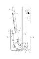
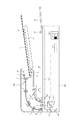
図1は本実施形態における自動原稿給紙装置(ADF)100と画像読取装置200の構成を示す断面図である。
[Image reading device and automatic document feeder]
FIG. 1 is a cross-sectional view showing a configuration of an automatic document feeder (ADF) 100 and an
図1は、原稿トレイ30が下降している状態を示している。ADF100は、1枚或いは複数枚の原稿で構成される原稿束Sを積載する原稿トレイ30と、原稿の搬送開始前に、原稿束Sが原稿トレイ30より突出して下流への進出を規制する分離ローラ対2と、給紙ローラ1とを有する。給紙が開始していない場合や原稿がセットされていない場合には、原稿トレイ30は下降可能な最下限の位置で停止している。なお、原稿を原稿トレイ30にセットしただけでは原稿トレイ30は上昇しない。原稿有無検知センサ17は原稿トレイ30の原稿の有無を検知する。底面検知センサ18は、原稿トレイ30が最下限位置まで下降していることを検知する。
FIG. 1 shows a state where the
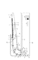
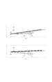
原稿トレイ30は、図4に示すように、リフタ機構31により原稿トレイ30を底面側から支えられつつ、リフタ機構31の回動軸32を中心に所定角度区間を回動することでリフタ板33が上下動作する。図4(a)に示すように、回動軸32が時計回りに回動することによりリフタ板33が上昇し、原稿トレイ30はリフタ板33により押し上げられるようにして上昇する。また、図4(b)に示すように、回動軸32が反時計回りに回動することによりリフタ板33が下降し、原稿トレイ30はリフタ板33による支持がなくなることで自然に下降する。
As shown in FIG. 4, the
原稿トレイ30を上昇させる場合、原稿トレイ30上にセットされた原稿束Sの最上面の原稿を原稿検知センサ19により検知することで、給送可能な給送位置まで原稿トレイ30が上昇したことが判断され、リフタ機構31の駆動が停止する。その結果、原稿トレイ30の上昇動作が停止する。図3は原稿トレイ30が原稿を給送可能な給送位置まで上昇した状態を示している。
When the
原稿トレイ30を下降させる場合、リフタ機構31により下降動作させ、原稿トレイ底面検知センサ18により原稿トレイ底面が検出されることで、原稿トレイ30が最下限位置まで下降したことを判断され、リフタ機構31の駆動が停止する。その結果、原稿トレイ30の下降動作が停止する。この最下限位置が原稿積載を待機する待機位置となる。
When the
原稿の読取開始指示が入力されると、画像読取装置200のスキャナユニット209が基準白色板219直下の位置まで移動し、シェーディング補正が実施される。シェーディング補正実施後、スキャナユニット209は流し読みガラス201直下の位置まで移動し、原稿が読み取り位置に到達するまで待機する。
When a document reading start instruction is input, the
一方、読取開始指示が入力されたことに応じて、原稿トレイ30が原稿給送可能な位置まで上昇した後、給送手段としての給紙ローラ1が原稿トレイ30に積載された原稿束Sの最上面の原稿上に落下し回転開始する。これにより、原稿束の最上面の原稿が給紙される。給紙ローラ1によって給送された原稿は分離ローラ対2の作用によって1枚に分離される。この分離は周知の分離技術によって実現されている。
On the other hand, in response to the input of the reading start instruction, after the
分離ローラ対2によって分離された原稿は、搬送ローラ対3により、レジストレーションローラ(以下レジストローラと称す)4へ搬送され、レジストローラ4に原稿を突き当てられる。これにより、原稿にループが形成され、原稿の先端側の斜行が解消される。
The document separated by the
レジストローラ4の下流側には、さらに給送ローラ5および原稿読取ローラ6が設けられ、給送ローラ5、原稿読取ローラ6及び原稿読取プラテンローラ7により流し読みガラス201上に送られる。なお、ガラス201に搬送される際に、リードセンサ12により原稿先端が検知される。リードセンサ12がオンしたタイミングから原稿読取ローラ6および原稿読取プラテンローラ7の駆動源(図示せず)のクロックを計数することで搬送中の原稿先端位置が検知される。原稿先端位置が予め決められている原稿画像先端基準位置に到達したことが検知されると、スキャナユニット209により流し読み画像取り込みが実施される。原稿読取プラテンローラ7により給送された原稿は、搬送ローラ8および搬送ローラ9で搬送され、排紙センサ13により原稿後端が検知されると、原稿後端検知タイミングをトリガとして、さらに排紙ローラ10まで搬送される。片面読み取りの場合は原稿はそのまま原稿排紙トレイ35へ排出される。
A
分離後センサ15で原稿後端が知されると、原稿トレイ30上の次原稿の有無が原稿有無検知センサ17で検知される。原稿有無検知センサ17により原稿トレイ30上の原稿無しを検知した場合には、原稿トレイ30が下降する。
When the trailing edge of the document is known by the post-separation sensor 15, the presence or absence of the next document on the
原稿の両面を読み取る場合は、排紙ローラ10に原稿を噛ませた状態で、排紙ローラ10を逆転させて排紙フラッパ21の位置を切り替えることにより、反転パス22へ原稿が移動する。移動した原稿はパス22からレジストローラ4へ突き当てられ、再度原稿にループが形成されることによって、原稿の先端の斜行が解消される。その後、給送ローラ5及び原稿読取プラテンローラ7により再び原稿を流し読みガラス201へ移動させることで、原稿の裏面が読み取られる。
When scanning both sides of the document, the document is moved to the reverse path 22 by switching the position of the sheet discharge flapper 21 by rotating the sheet discharge roller 10 in the reverse direction while the document is caught in the sheet discharge roller 10. The moved original is abutted against the
また、原稿トレイ30には、積載された原稿束Sの幅方向にスライド可能なガイド規制板(図示せず)が設けられているとともに、このガイド規制板に連動して原稿幅を検出する原稿幅検知センサ(図示せず)が設けられている。原稿幅検知センサとレジ前センサ16で原稿の先端を検出し、分離後センサ15により原稿の後端を検出することにより原稿長を検出され、検知した原稿長と原稿幅検知センサとの組み合わせから、原稿サイズが判別される。
The
画像読取装置200は、原稿固定読みの場合は、光学スキャナユニット209が図1矢印に示す副走査方向に移動することで、原稿台ガラス202上に載置された原稿の画像が読み取られる。また、原稿流し読みの場合は、光学スキャナユニット209をADF100の原稿読取プラテンローラ7の読取中心位置に来るように移動し、原稿読取プラテンローラ7の読取中心位置でADF100で搬送中の原稿を読み取る。原稿は、流し読みガラス201、原稿台ガラス202、ランプ203とミラー204を有するスキャナユニット209、ミラー205、206、レンズ207、CCDセンサユニット210を備えた光学系で読み取られる。読み取られた原稿の画像情報は光電変換されて、図示しないコントローラ部に画像データとして転送される。
In the case of the original fixed reading, the
また、基準白色板219は、シェーディングによる白レベルの基準データを作成するための白板である。なおCCDセンサユニット210は、カラー画像読取用(RGB)3ラインセンサユニット212、白黒画像読取用ラインセンサユニット211で構成される。
The reference
[ブロック図の説明]
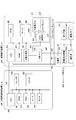
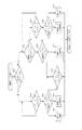
図2はADF100及び画像読取装置200の構成を示すブロック図である。
[Explanation of block diagram]
FIG. 2 is a block diagram illustrating the configuration of the
2−aはADF100の制御ブロックであり、制御手段としてのCPU300、リードオンリーメモリ(以下、ROM)301、ランダムアクセスメモリ(以下、RAM)302、出力ポート、及び、入力ポートを備えている。ROM301には、制御用プログラムが格納されており、RAM302には、入力データや作業用データが格納されている。出力ポートには、各種搬送用のローラを駆動するモータ303、ソレノイド306、クラッチ307が接続されており、入力ポートには、各種センサ304がそれぞれ接続されている。図1および図3に示されるリードセンサ12、排紙センサ13、分離後センサ15、原稿有無検知センサ17等の各種センサが図2の各種センサ304で表されている。図1および図3に図示しない駆動源等のモータは図2のモータ303、同様に図示しないソレノイドおよびクラッチはソレノイド306、クラッチ307で表されている。
2-a is a control block of the
CPU300は、バスラインを介して接続されたROM301に格納された制御プログラムにしたがって原稿搬送を制御する。また、CPU300は、画像読取装置200の中央演算処理装置(CPU)321と制御用通信線351を介してシリアル通信を行い、画像読取装置200との間で制御データの授受を行うようになっている。また、原稿画像データの先端の基準となる画先信号も制御用通信線351を通して画像読取装置200に通知される。
The
2−bは、画像読取装置200の制御ブロックである。CPU321は画像読取装置200の制御をすべて行っている。CPU321にはプログラムを格納したROM322,ワークエリアとして使用されるRAM323が接続される。326は光学系モータドライブ部であり、光学系駆動モータを駆動させるためのドライバ回路である。画像読取装置200には、ランプ327、CCDセンサユニット210が接続されている。CPU321は、光学系モータドライバ部326を制御し、画像処理部325を介してCCDセンサユニット210を制御することで画像読取処理を実施している。
Reference numeral 2-b denotes a control block of the
紙搬送を実現するために、CPU321はCPU300に制御用通信線351を介して紙搬送制御についてのコマンドを指示する。指示されたCPU300が搬送パス上に設置されている各センサ304をモニタし、負荷である搬送用のモータ303、ソレノイド306、クラッチ307を駆動することで、紙搬送制御を実現している。このように、CPU321はADF100による紙搬送と、画像読取装置200による画像読取制御を行っている。
In order to realize paper conveyance, the
CCDセンサユニット210から出力される画像信号はデジタル画像データに変換され、さらに画像処理部325でシェーディングをはじめとして、各種画像処理が施されて、画像メモリ部329に書き込まれる。画像メモリ部329に書き込まれたデータは順次、画像転送用クロック信号線を含むコントローラインターフェース画像通信線353を通してコントローラ部400へ送信される。
The image signal output from the
2−cは画像処理用コントローラ部400の回路ブロックである。コントローラ部400は、画像読取装置200、自動原稿給紙装置100を含む画像読取システムとしての全体を制御する装置であり、コントローラ制御部401、変倍回転等の画像制御回路402、補正回路403を有している。
コントローラ部400は、操作部405からのキー入力を判断し、コピー等ジョブの設定情報やジョブ開始トリガを判断する。
Reference numeral 2-c denotes a circuit block of the image processing controller unit 400. The controller unit 400 is a device that controls the entire image reading system including the
The controller unit 400 determines key input from the
原稿給送装置100、画像読取装置200、コントローラ部400を1つのCPUで制御する構成としてもよい。例えば、画像読取装置200のCPU321が原稿給送装置100や操作部405等の制御を行う構成としてもよい。
The
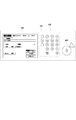
図5は操作部405を示す図である。406は、コピージョブ開始指示、ファクシミリ送信や画像読取の開始指示を入力するスタートキーである。また、407の点線で囲まれた領域はテンキーなどの入力キーである。408の点線で囲まれた領域は、タッチパネルディスプレイで構成され、コピーや画像読み取りの条件の設定を行ったり、種々の情報が表示される。
FIG. 5 is a diagram showing the
[原稿トレイの上昇時間]
一例として、本実施形態で使用される原稿トレイ30は、最大で約300枚の原稿を積載可能な構成となっている。そのため、原稿トレイ30が昇降する構成となっているが、原稿トレイ30原稿トレイ30に積載される原稿束Sの量に応じて、リフタ上昇時間が異なってくる。例えば、原稿束Sの量が約300枚の場合には、リフタの上昇量はわずかであり、上昇に要する時間は0.5秒程度と短い。一方、原稿束Sの量が1枚の場合には、給紙搬送路と原稿トレイ30上の最上面原稿との高さの差が多い、2.5秒程度必要となる。
[Rise time of document tray]
As an example, the
[原稿トレイの上昇動作]
以下、本実施形態におけるADF100の原稿トレイ30の昇上昇動作について説明する。
[Upper movement of document tray]
Hereinafter, the ascending / descending operation of the
原稿を原稿トレイ30にセットする際に、ユーザの使用環境により使い勝手のよい原稿トレイ上昇方法が異なる。そこで、本実施形態では、原稿トレイ30の上昇動作の方法を選択可能としている。図6は原稿トレイ30の上昇方法を選択するための操作画面である。この画面409は図5のタッチパネルディスプレイ408に表示される。画面409では、第1モードおよび第2モードのいずれかを選択できるようになっており、機器の初期設定として、ユーザが予め設定しておく。第1モードでは、スタートキー406が押下されたことに応答して原稿トレイ30が上昇開始する。第2モードでは、ジョブ開始のためのスタートキー406の押下前でも、407のキーの何れか或いはタッチパネルディスプレイ408のキーの何れか、即ち、スタートキー以外の操作キーが押下されたことに応答して原稿トレイ30が上昇開始する。なお、第2モードでもスタートキー406が押下されたことに応じても原稿トレイ30が上昇を開始する。
When a document is set on the
第1モードが選択されている状態では、原稿を原稿トレイ30にセットした後にスタートキーを押下しない限り、原稿トレイ30は上昇しない。また、第1モードでは、原稿トレイ30への原稿のセットと画像形成や読み取りのモード設定のためのキー操作はどちらが先に行われても構わない。従って、確実に原稿トレイ30に原稿をセットしてから原稿トレイを上昇させることができる。
When the first mode is selected, the
また、ユーザが原稿を原稿トレイ30にセットした後に、画像形成のモードの設定のためスタートキー以外のキーを押下する場合は、像形成ジョブを実行する可能性が高い。そこで、第2モードが選択されている状態では、原稿を原稿トレイ30にセットした後に、モード設定のために何れかのキーを押下した時点で原稿トレイ30が上昇開始する。従って、スタートキー406を押下する前に、原稿トレイ30の上昇を開始させておくことができ、積載される原稿の枚数が少なくても原稿給送開始までの時間を短縮できる。更に、第1モードと同様、確実に原稿トレイ30に原稿をセットしてから原稿トレイを上昇させることができる。
Further, when the user presses a key other than the start key for setting the image forming mode after setting the document on the
また、大量の原稿を小分けにして原稿トレイへセットすることが考えられる。しかし、第2モードのみを有する構成では、小分けした原稿を原稿トレイへセットしている途中で、誤って、操作部のキーに触れてしまい、意図しないタイミングで原稿トレイが上昇してしまう惧れがある。そこで、第1モードを選択可能とすることにより、確実に原稿を原稿トレイへセットしたことを確認してからスタートキーを押下して原稿トレイを上昇させることもできる。 It is also conceivable to divide a large amount of originals into small parts and place them on the original tray. However, in the configuration having only the second mode, the document tray may be lifted at an unintended timing by accidentally touching the key of the operation unit while setting the divided document on the document tray. There is. Therefore, by making it possible to select the first mode, it is possible to raise the document tray by pressing the start key after confirming that the document is surely set on the document tray.
図2のADF100のCPU300は、各種センサ304や各種モータ303等を制御しており、読取装置200のCPU321との通信により、各種センサ304情報や各種モータ303の状態を制御情報として読取装置200のCPU321に通知している。読取装置200のCPU321は、ADF100との通信により得られるADF100の各種センサ304、各種モータ303の制御情報に基づき、必要に応じてADF100に実施させる処理をコマンドとしてADF100のCPU300に指示する。例えば、給紙動作を開始させるために給紙モータを回転させたり、分離後センサ15の情報に応じてモータを停止させる等の処理コマンドがCPU321からCPU300へ通知される。
The
また、読取装置200のCPU321は、コントローラ部400の制御部401との通信により、コントローラ部400で検知される操作部405からの入力情報を得ることで、ユーザのキー操作を検知することができる。こうして、読取装置200のCPU321はコントローラ部400の制御部401との通信により、常に操作部405で入力された情報を得ることができる。これらの情報の中には、スタートキー406の操作やスタートキー406以外の操作部405のキー操作が含まれる。読取装置200のCPU321は、操作部405から入力される情報を監視し、ADF100へコマンドを送信したり、読取装置200の制御を実施している。
Further, the
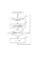
図11は読取装置200のCPU321の制御フローチャートである。CPU321は、ジョブの有無にかかわらず、装置電源(図示しない)がONしている限り、図11のフローチャートを実行する。CPU321は、ADF100のCPU300と常時通信し、ADF100の制御情報を入手するとともに、必要に応じでADF100のCPU300に制御コマンドを通知する(S1202)。更に、CPU321は、コントローラ部400の制御部401とも常時通信を実施しており、コントローラ部400との情報更新を実行する(S1203)。そして、CPU321は、制御部401との通信で更新された情報に応答したイベントがあるかをチェックしている(S1204)。例えば、ユーザがジョブを開始するため、図5に示すスタートキー406を押下すると、制御部401はキー入力されたことを認識し、読取装置200のCPU321に通知する。ジョブ開始通知を受信したCPU321は、ジョブ開始通知に応答するイベント、すなわち、ジョブを開始させるため読取装置200の準備およびADF100の原稿搬送準備を行う(S1205)。イベント実施すると、ADF100のCPU300との通信処理(S1202)に戻る。制御401との通信で更新された情報に応答したイベントがなければ、ADF100のCPU300との通信処理(S1202)に戻る。S1202〜S1205までの処理が装置電源がONしている限り繰り返し実施される。
FIG. 11 is a control flowchart of the
なお、原稿トレイ30を上昇させる場合には、読取装置200のCPU321がADF100のCPU300に対して、原稿トレイ30を上昇させるべく、リフタ機構31の駆動源のリフタモータを回転させる指示を通知する。CPU300はリフタモータ回転指示の通知を受信すると、各種モータ303のうちのリフタモータを回転させるように動作する。なお、リフタモータにより原稿トレイ30が上昇し、原稿検知センサ19により、原稿束Sの最上面の原稿が検知されると、ADF100のCPU300から読取装置200のCPU321に原稿トレイ30の上昇終了が通知される。そして、読取装置200のCPU321は、原稿トレイ30の上昇を停止させるために、ADF100のリフタ機構31のリフタモータの駆動を停止させる指示をADF100のCPU300に通知する。リフタモータ停止通知を受信したCPU300は、リフタモータ停止するように制御する。なお、CPU300が原稿検知センサ19の出力に基づいてリフタモータの駆動を停止させてもよい。
When the
図6に示す設定画面409での選択結果も、制御部401からCPU321へ通知される。CPU321は、通知された情報に応じたイベントとして、選択された原稿トレイ30の上昇方法に応じた原稿トレイ上昇制御を実施する。
The selection result on the
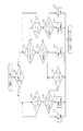
次に、原稿トレイ上昇制御について図7のフローチャートに基づいて説明する。このフローチャートは読取装置のCPU321により実行される。
Next, the document tray raising control will be described based on the flowchart of FIG. This flowchart is executed by the
CPU321は、制御部401からの通信により原稿トレイ30の上昇モードが第1モードか第2モードの何れであるか判断する(S702)。第1モードが選択されている場合、CPU321は、スタートキー406が押下されたか否かを判断する(S704)。スタートキー406が押下されると、CPU321は、原稿トレイ30上に原稿が載置されているか否かをCPU300との通信により判断する(705)。原稿トレイ30に原稿が載置されていれば、CPU321は、ADF100を使用したジョブであると判断し、原稿トレイ30を上昇させる指示及び原稿給送の指示をCPU300へ通知する(S712)。原稿トレイ30に原稿が載置されていなければ、CPU321は、プラテンガラス202にセットされた原稿の読み取りであると判断して圧板ジョブとして処理を行う(S711)。このように、第1モードが選択されている場合には、スタートキー406の入力に応答して原稿トレイの上昇開始するようにしているため、確実に原稿をセットすることができる。
The
また、ステップS702で、第2モードが選択されていることが判断された場合、CPU321はスタートキー406以外のキーが入力されたか否かを制御部401との通信により判断する(S707)。スタートキー406以外のキーが入力された場合、CPU321は、原稿トレイ30に原稿が載置されているか否かをCPU300との通信により判断する(S708)。原稿トレイ30に原稿が載置されている場合、CPU321は、ADF100を使用したジョブであると判断し、原稿トレイ30を上昇させる指示及び原稿給送の指示をCPU300へ通知する(S713)。そして、CPU321はスタートキー406が入力されるのを待って(S716)、CPU300へ原稿給送の指示をする。一方、ステップS707でスタートキー406以外のキーが入力されたことが判断されていない場合、CPU321はスタートキー406が入力されたか否かを制御部401との通信により判断する(S709)。ステップS708で原稿トレイ30に原稿がセットされていない場合も同様に、ステップS709へ進む。スタートキー406が入力されていない場合は、ステップS707からの処理が繰り返される。スタートキー406が入力された場合、CPU321は、原稿トレイ30に原稿が載置されているか否かをCPU300との通信により判断する(S710)。原稿トレイ30に原稿が載置されている場合、CPU321は、ADF100を使用したジョブであると判断し、原稿トレイ30を上昇させる指示及び原稿給送の指示をCPU300へ通知する(S714)。原稿トレイ30に原稿が載置されていなければ、CPU321は、プラテンガラス202にセットされた原稿の読み取りであると判断して圧板ジョブとして処理を行う(S715)。このように、第2モードでは、原稿を原稿トレイにセットした後に、像形成や読み取りのモードを設定するために、操作部405のキーを操作したことに応答して原稿トレイ30の上昇が開始されるので、原稿給送の開始までの時間が短縮できる。即ち、スタートキー406を押下する頃には原稿トレイ30の上昇が完了しているか、もうすぐ完了する状態となっているので、原稿の枚数が少ない場合でも原稿トレイ30の上昇を待つ時間が短くなる。
If it is determined in step S702 that the second mode is selected, the
(第2の実施の形態)
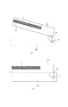
ADF100でA3サイズ等搬送方向に長い原稿を扱うことがある。この場合のユーザの操作として、図8に示す様に、排紙トレイ35上から読み取りが終了した原稿が落ちないように排紙トレイ35から排紙サブトレイ36を引き出すことが想定される。即ち、ジョブが開始される前にユーザが行う操作として、操作部材としての排紙サブトレイ36が引き出されたことを排紙サブトレイ36近傍の排紙サブトレイセンサ37で検知する。排紙サブトレイ36が引き出されたことが検知された直後、原稿トレイ30に原稿がセットされていた場合には、その検知に応答して原稿トレイ30の上昇開始させる。これにより第1の実施形態と同様に、スタートキー406の押下前に原稿トレイ30の上昇を開始させることができる。
(Second Embodiment)
The
以下、第2の実施形態における原稿トレイ30の上昇動作の制御について図9のフローチャートを用いて説明する。
Hereinafter, control of the raising operation of the
第1モードが選択されている場合の処理は、図7のステップS703,S704,S705,S711,S712と同じである。第2モードが選択されている場合、CPU321は、排紙サブトレイ36が引き出されたか否かをCPU300との通信により判断する(S907)。CPU300は排紙サブトレイセンサ37がオフしたことにより排紙サブトレイ36が引き出されたことを検知し、CPU321へ通知する。ステップS908及びS909以降の処理は図7のステップS708及びS709以降の処理と同じである。
The processing when the first mode is selected is the same as steps S703, S704, S705, S711, and S712 in FIG. When the second mode is selected, the
このように、第2モードが選択されている場合には、スタートキー406の押下前に排紙サブトレイ36の引き出しが検知されたことに応答して原稿トレイ30を給紙可能な給紙搬送路の高さまで上昇させる。これにより、原稿給送を開始するまでの時間を短縮できる。
As described above, when the second mode is selected, a paper feed conveyance path capable of feeding the
また、A3サイズ等の搬送方向に長い原稿を支持するための原稿サブトレイを原稿トレイ30から引き出し可能に設け、原稿が原稿トレイ30に積載されている状態で、この原稿サブトレイの引き出しに応答して原稿トレイ30の上昇を開始させるようにしてもよい。この場合の原稿サブトレイは、原稿搬送方向の後端側を支持する役目を果たす。
In addition, a document sub-tray for supporting a document that is long in the transport direction, such as an A3 size, is provided so as to be able to be pulled out from the
(他の実施の形態)
ユーザによっては、直前のコピージョブがADFを使用しない圧板ジョブかもしれないと考えて、原稿を原稿トレイ30にセットした後にADF100を開閉して、原稿台上の原稿の有無を確認する操作を実施するかもしれない。図10(a)はADF100が開けられた場合の側面から見た図であり、図10(b)ではADF100が閉じられた場合の側面から見た図である。ADF開閉検知センサ41がADF開閉検知フラグ40を検知しているかどうかでADF100が開いた状態であるか閉じた状態であるかを検知することができる。従って、第2モードが選択されている状態で、ADF100が開かれた後に閉じられたことが検知され、且つ、閉じられた時点で原稿トレイ30に原稿が載置されていることが検知されていることに応答して、原稿トレイ30の上昇を開始するようにしてもよい。
(Other embodiments)
Some users consider that the immediately preceding copy job may be a pressure plate job that does not use ADF, and after opening the document on the
17 原稿有無検知センサ
30 原稿トレイ
100 自動原稿給紙装置、
200 画像読取装置
300 原稿給送装置のCPU
321 画像読取装置のCPU
405 操作部
406 スタートキー
407 テンキー等
408 タッチパネルディスプレイ
17 Document presence /
200
321 CPU of image reading apparatus
405
Claims (5)
前記原稿トレイに原稿が載置されたことを検出する原稿検知センサと、
前記原稿トレイを、原稿積載を待機する待機位置と原稿給送が可能な給送位置との間で上昇及び下降させる駆動手段と、
前記原稿トレイが前記給送位置にあるときに、原稿の給送を行う給送手段と、
原稿の給送を伴う処理の開始を指示するスタートキーと、
前記処理の条件を設定するための操作キーと、
前記原稿トレイに原稿が載置されていることが前記原稿検知センサにより検出されている状態で、前記スタートキーと前記操作キーの何れの押下にも応答して前記原稿トレイを上昇させる制御手段と、
を有することを特徴とする原稿給送装置。 A document tray for loading documents,
A document detection sensor for detecting that a document is placed on the document tray;
Drive means for raising and lowering the document tray between a standby position for waiting for document stacking and a feeding position capable of feeding documents;
A feeding means for feeding a document when the document tray is at the feeding position;
A start key for instructing the start of processing accompanied by document feeding;
Operation keys for setting the processing conditions;
Control means for raising the document tray in response to pressing of either the start key or the operation key while the document detection sensor detects that the document is placed on the document tray; ,
A document feeder characterized by comprising:
前記原稿トレイに原稿が載置されたことを検出する原稿検知センサと、
前記原稿トレイを、原稿積載を待機する待機位置と原稿給送が可能な給送位置との間で上昇及び下降させる駆動手段と、
前記原稿トレイが前記給送位置にあるときに、原稿の給送を行う給送手段と、
原稿の給送を伴う処理の開始を指示するスタートキーと、
前記スタートキーとは別に設けられ、前記処理の準備のために操作される操作部材と、
前記原稿トレイに原稿が載置されていることが前記原稿検知センサにより検出されている状態で、前記スタートキーの押下と前記操作部材の操作の何れにも応答して前記原稿トレイを上昇させる制御手段と、
を有することを特徴とする原稿給送装置。 A document tray for loading documents,
A document detection sensor for detecting that a document is placed on the document tray;
Drive means for raising and lowering the document tray between a standby position for waiting for document stacking and a feeding position capable of feeding documents;
A feeding means for feeding a document when the document tray is at the feeding position;
A start key for instructing the start of processing accompanied by document feeding;
An operating member provided separately from the start key and operated for preparation of the processing;
Control for raising the document tray in response to both pressing of the start key and operation of the operation member in a state where the document detection sensor detects that the document is placed on the document tray Means,
A document feeder characterized by comprising:
Priority Applications (2)
| Application Number | Priority Date | Filing Date | Title |
|---|---|---|---|
| JP2008321630A JP2010143694A (en) | 2008-12-17 | 2008-12-17 | Document feeding apparatus |
| US12/635,057 US8128081B2 (en) | 2008-12-17 | 2009-12-10 | Document feeding apparatus |
Applications Claiming Priority (1)
| Application Number | Priority Date | Filing Date | Title |
|---|---|---|---|
| JP2008321630A JP2010143694A (en) | 2008-12-17 | 2008-12-17 | Document feeding apparatus |
Publications (2)
| Publication Number | Publication Date |
|---|---|
| JP2010143694A true JP2010143694A (en) | 2010-07-01 |
| JP2010143694A5 JP2010143694A5 (en) | 2012-02-09 |
Family
ID=42239559
Family Applications (1)
| Application Number | Title | Priority Date | Filing Date |
|---|---|---|---|
| JP2008321630A Pending JP2010143694A (en) | 2008-12-17 | 2008-12-17 | Document feeding apparatus |
Country Status (2)
| Country | Link |
|---|---|
| US (1) | US8128081B2 (en) |
| JP (1) | JP2010143694A (en) |
Cited By (3)
| Publication number | Priority date | Publication date | Assignee | Title |
|---|---|---|---|---|
| JP2017024848A (en) * | 2015-07-21 | 2017-02-02 | キヤノン株式会社 | Image reading device, and image formation device |
| JP2019186893A (en) * | 2018-04-17 | 2019-10-24 | シャープ株式会社 | Document reading device, document reading method, and control program |
| JP2021028276A (en) * | 2020-11-12 | 2021-02-25 | セイコーエプソン株式会社 | Medium conveyance device and image reader |
Families Citing this family (6)
| Publication number | Priority date | Publication date | Assignee | Title |
|---|---|---|---|---|
| CN110191250B (en) * | 2014-12-12 | 2022-10-14 | 佳能株式会社 | Printing control apparatus and control method thereof |
| KR20190093021A (en) | 2018-01-31 | 2019-08-08 | 휴렛-팩커드 디벨롭먼트 컴퍼니, 엘.피. | Document feeder using one motor and image reading apparatus including the same |
| US10571846B2 (en) | 2018-03-13 | 2020-02-25 | Kabushiki Kaisha Toshiba | Image forming apparatus, document reading device and conveyance method |
| US20210070564A1 (en) | 2019-09-09 | 2021-03-11 | Toshiba Tec Kabushiki Kaisha | Sheet conveying device, image forming apparatus, and sheet presence or absence determination method |
| JP7562290B2 (en) * | 2020-05-27 | 2024-10-07 | キヤノン株式会社 | Sheet conveying device, image reading device and image forming device |
| JP7592437B2 (en) * | 2020-09-14 | 2024-12-02 | キヤノン株式会社 | IMAGE PROCESSING APPARATUS, CONTROL METHOD FOR IMAGE PROCESSING APPARATUS, AND PROGRAM |
Citations (3)
| Publication number | Priority date | Publication date | Assignee | Title |
|---|---|---|---|---|
| JPH11237770A (en) * | 1998-02-24 | 1999-08-31 | Ricoh Co Ltd | Document feeder |
| JP2004166052A (en) * | 2002-11-14 | 2004-06-10 | Sharp Corp | Document feeding device, image reading device, image forming device |
| JP2005277624A (en) * | 2004-03-24 | 2005-10-06 | Fuji Xerox Co Ltd | Device and method for automatically feeding document |
Family Cites Families (2)
| Publication number | Priority date | Publication date | Assignee | Title |
|---|---|---|---|---|
| JP3544049B2 (en) | 1995-12-14 | 2004-07-21 | 株式会社リコー | Document feeder |
| US6091927A (en) | 1997-11-17 | 2000-07-18 | Ricoh Company, Ltd. | Apparatus and method for feeding documents to an image forming apparatus, scanner, or the like |
-
2008
- 2008-12-17 JP JP2008321630A patent/JP2010143694A/en active Pending
-
2009
- 2009-12-10 US US12/635,057 patent/US8128081B2/en active Active
Patent Citations (3)
| Publication number | Priority date | Publication date | Assignee | Title |
|---|---|---|---|---|
| JPH11237770A (en) * | 1998-02-24 | 1999-08-31 | Ricoh Co Ltd | Document feeder |
| JP2004166052A (en) * | 2002-11-14 | 2004-06-10 | Sharp Corp | Document feeding device, image reading device, image forming device |
| JP2005277624A (en) * | 2004-03-24 | 2005-10-06 | Fuji Xerox Co Ltd | Device and method for automatically feeding document |
Cited By (5)
| Publication number | Priority date | Publication date | Assignee | Title |
|---|---|---|---|---|
| JP2017024848A (en) * | 2015-07-21 | 2017-02-02 | キヤノン株式会社 | Image reading device, and image formation device |
| JP2019186893A (en) * | 2018-04-17 | 2019-10-24 | シャープ株式会社 | Document reading device, document reading method, and control program |
| JP7113653B2 (en) | 2018-04-17 | 2022-08-05 | シャープ株式会社 | Document reading device and document reading method |
| JP2021028276A (en) * | 2020-11-12 | 2021-02-25 | セイコーエプソン株式会社 | Medium conveyance device and image reader |
| JP7089682B2 (en) | 2020-11-12 | 2022-06-23 | セイコーエプソン株式会社 | Media transfer device, image reader |
Also Published As
| Publication number | Publication date |
|---|---|
| US20100148420A1 (en) | 2010-06-17 |
| US8128081B2 (en) | 2012-03-06 |
Similar Documents
| Publication | Publication Date | Title |
|---|---|---|
| JP2010143694A (en) | Document feeding apparatus | |
| JP2011057304A (en) | Sheet feeding apparatus, image reading apparatus and image forming apparatus | |
| US9094555B2 (en) | Reading device, image forming apparatus including the same, and control method for reading device | |
| JP2018093328A (en) | Image reader and method of controlling image reader | |
| US11546482B2 (en) | Document reading apparatus, control method thereof, and storage medium | |
| JP6228155B2 (en) | Image reading apparatus and image forming apparatus | |
| JP5081895B2 (en) | Paper feeding device, document conveying device, image forming device | |
| JP2014103563A (en) | Image reading apparatus | |
| US20160185138A1 (en) | Image forming apparatus | |
| JP6676298B2 (en) | Image reading device and image forming device | |
| WO2023276806A1 (en) | Document conveying device | |
| JP2021187590A (en) | Sheet transfer device, image reader and image forming device | |
| JP7592421B2 (en) | Reading device, its control method, and program | |
| JP2016210559A (en) | Sheet feeding apparatus, image reading apparatus, and image forming apparatus | |
| JP7592437B2 (en) | IMAGE PROCESSING APPARATUS, CONTROL METHOD FOR IMAGE PROCESSING APPARATUS, AND PROGRAM | |
| JP2003054769A (en) | Capacity control system for paper feeding elevator | |
| JP2008280153A (en) | Sheet conveying device and document reading device | |
| JP3751294B2 (en) | Sheet feeding apparatus, image reading apparatus, and image forming apparatus | |
| JP2017043463A (en) | Sheet feeding device and image formation apparatus | |
| JP2024164707A (en) | Document conveying device and image forming device | |
| JP2017024847A (en) | Image reading apparatus and image forming apparatus | |
| JP2016088693A (en) | Sheet feeding device | |
| JP2006021867A (en) | Image forming device, and sheet feed control method for the image forming device | |
| JP7443028B2 (en) | Image reading device | |
| JP2021134048A (en) | Image reader |
Legal Events
| Date | Code | Title | Description |
|---|---|---|---|
| RD01 | Notification of change of attorney |
Free format text: JAPANESE INTERMEDIATE CODE: A7421 Effective date: 20100630 |
|
| A521 | Request for written amendment filed |
Free format text: JAPANESE INTERMEDIATE CODE: A523 Effective date: 20111219 |
|
| A621 | Written request for application examination |
Free format text: JAPANESE INTERMEDIATE CODE: A621 Effective date: 20111219 |
|
| A977 | Report on retrieval |
Free format text: JAPANESE INTERMEDIATE CODE: A971007 Effective date: 20130128 |
|
| A131 | Notification of reasons for refusal |
Free format text: JAPANESE INTERMEDIATE CODE: A131 Effective date: 20130205 |
|
| A521 | Request for written amendment filed |
Free format text: JAPANESE INTERMEDIATE CODE: A523 Effective date: 20130408 |
|
| A02 | Decision of refusal |
Free format text: JAPANESE INTERMEDIATE CODE: A02 Effective date: 20130507 |