JP2010143571A - Motor vehicle brake master cylinder seal - Google Patents
Motor vehicle brake master cylinder seal Download PDFInfo
- Publication number
- JP2010143571A JP2010143571A JP2009286241A JP2009286241A JP2010143571A JP 2010143571 A JP2010143571 A JP 2010143571A JP 2009286241 A JP2009286241 A JP 2009286241A JP 2009286241 A JP2009286241 A JP 2009286241A JP 2010143571 A JP2010143571 A JP 2010143571A
- Authority
- JP
- Japan
- Prior art keywords
- lip
- master cylinder
- housing
- piston
- pressed against
- Prior art date
- Legal status (The legal status is an assumption and is not a legal conclusion. Google has not performed a legal analysis and makes no representation as to the accuracy of the status listed.)
- Granted
Links
Images
Classifications
-
- B—PERFORMING OPERATIONS; TRANSPORTING
- B60—VEHICLES IN GENERAL
- B60T—VEHICLE BRAKE CONTROL SYSTEMS OR PARTS THEREOF; BRAKE CONTROL SYSTEMS OR PARTS THEREOF, IN GENERAL; ARRANGEMENT OF BRAKING ELEMENTS ON VEHICLES IN GENERAL; PORTABLE DEVICES FOR PREVENTING UNWANTED MOVEMENT OF VEHICLES; VEHICLE MODIFICATIONS TO FACILITATE COOLING OF BRAKES
- B60T11/00—Transmitting braking action from initiating means to ultimate brake actuator without power assistance or drive or where such assistance or drive is irrelevant
- B60T11/10—Transmitting braking action from initiating means to ultimate brake actuator without power assistance or drive or where such assistance or drive is irrelevant transmitting by fluid means, e.g. hydraulic
- B60T11/16—Master control, e.g. master cylinders
- B60T11/236—Piston sealing arrangements
-
- F—MECHANICAL ENGINEERING; LIGHTING; HEATING; WEAPONS; BLASTING
- F16—ENGINEERING ELEMENTS AND UNITS; GENERAL MEASURES FOR PRODUCING AND MAINTAINING EFFECTIVE FUNCTIONING OF MACHINES OR INSTALLATIONS; THERMAL INSULATION IN GENERAL
- F16J—PISTONS; CYLINDERS; SEALINGS
- F16J15/00—Sealings
- F16J15/16—Sealings between relatively-moving surfaces
- F16J15/32—Sealings between relatively-moving surfaces with elastic sealings, e.g. O-rings
- F16J15/3204—Sealings between relatively-moving surfaces with elastic sealings, e.g. O-rings with at least one lip
- F16J15/3232—Sealings between relatively-moving surfaces with elastic sealings, e.g. O-rings with at least one lip having two or more lips
- F16J15/3236—Sealings between relatively-moving surfaces with elastic sealings, e.g. O-rings with at least one lip having two or more lips with at least one lip for each surface, e.g. U-cup packings
Landscapes
- Engineering & Computer Science (AREA)
- Mechanical Engineering (AREA)
- General Engineering & Computer Science (AREA)
- Transportation (AREA)
- Transmission Of Braking Force In Braking Systems (AREA)
- Sealing With Elastic Sealing Lips (AREA)
Abstract
【課題】静的シーリングリップ部による小さな固体粒子の捕捉を防止するようにした自動車用の液圧式制動回路用マスターシリンダを提供する。
【解決手段】 マスターシリンダ本体のハウジング(6)内に配置された環状シール(1)を備え、このシールは、ピストンを取り囲み、このピストンが後休止位置にある場合にピストンの環状溝(20)に嵌着する動的内側シーリングリップ部(14)と、ハウジングの壁に押し付けられた静的外側シーリングリップ部(10)と、このシールのハウジングの壁に押し付けられ、外側リップ部とともに液体の小さな閉鎖容積(V)を形成する追加の静的シーリングリップ部(16)とを含む。
【選択図】図1There is provided a master cylinder for a hydraulic brake circuit for an automobile which prevents the capture of small solid particles by a static sealing lip.
An annular seal (1) disposed within a housing (6) of a master cylinder body, which surrounds the piston and when the piston is in a rear rest position, the annular groove (20) of the piston. A dynamic inner sealing lip (14) that fits into the housing, a static outer sealing lip (10) pressed against the housing wall, and a small liquid with the outer lip pressed against the housing wall of the seal. And an additional static sealing lip (16) that forms a closed volume (V).
[Selection] Figure 1
Description
本発明は、本質的には、特に自動車用のブレーキマスターシリンダ用のシールに関する。 The invention relates essentially to a seal for a brake master cylinder, in particular for motor vehicles.
自動車のブレーキ制御装置は、一般的には、液体圧力を液圧回路を介してレシーバーに伝達するため、マスターシリンダに作用するブレーキペダルを含む。レシーバーが様々なホイールを制動する。 A vehicle brake control device generally includes a brake pedal that acts on a master cylinder to transmit fluid pressure to a receiver via a fluid pressure circuit. The receiver brakes the various wheels.
ブレーキペダルはピストンに作用し、ピストンは、シールを含む本体内で軸線方向に摺動する。シールは、大気圧の液体のリザーバを含む後容積を、ピストンの変位によって加圧されるチャンバを含む前容積から分離するため、ピストンに押し付けられるリップ部を含む。 The brake pedal acts on the piston, which slides axially within the body including the seal. The seal includes a lip that is pressed against the piston to separate the rear volume containing the reservoir of atmospheric liquid from the front volume containing the chamber pressurized by the displacement of the piston.
この種のブレーキマスターシリンダは、米国特許第6,272,858号に記載されている。これは、二つのリップ部を持つ円形シールを有する。内側リップ部がピストンを取り囲み、動的シールを提供する。ピストンが休止時に後位置にある場合、内側リップ部は、深さが浅く且つ僅かに傾斜した側壁を持つピストン溝に入る。 A brake master cylinder of this kind is described in US Pat. No. 6,272,858. This has a circular seal with two lips. An inner lip surrounds the piston and provides a dynamic seal. When the piston is in its rear position when at rest, the inner lip enters the piston groove with a shallow wall and a slightly inclined side wall.
ピストンがこの休止位置にある場合、ピストンに形成されており且つ溝に開放した半径方向の穿孔(例えば、ドリル穴)が、リップシールの内側リップ部の後方に位置決めされ、圧力チャンバを液体リザーバと連通し、必要であれば液圧回路の容積を再調節する。 When the piston is in this rest position, a radial perforation (eg, a drill hole) formed in the piston and open into the groove is positioned behind the inner lip portion of the lip seal to connect the pressure chamber to the liquid reservoir. Communicate and readjust the hydraulic circuit volume if necessary.
リップシールは、ピストンを取り囲む本体の環状ハウジング内で軸線方向に楔をなし、この環状ハウジングの円筒形の底部に押し付けられて、圧力チャンバと後容積との間に静的シールを提供する外側リップ部を備えている。 The lip seal is axially wedged within the annular housing of the body surrounding the piston and is pressed against the cylindrical bottom of the annular housing to provide a static seal between the pressure chamber and the rear volume Department.
このマスターシリンダの一つの重要な欠点は、静的シーリングリップ部(静的な封止用のリップ部)のところに、小さな固体粒子が、圧力回路が一杯に充填された場合の液体の移動により、例えばこのリップ部の下に引っ掛かり、静的状態で外径方向に常に押し付けられるリップ部によって、捕捉されたままになってしまう可能性があるということである。かくして、リップ部の下に引っ掛かった粒子は、最終的には漏れを引き起こしてしまう可能性がある。というのは、リップ部が、もはや対向する表面に均等に圧接されないためである。 One important drawback of this master cylinder is that at the static sealing lip (static sealing lip), small solid particles are moved by liquid movement when the pressure circuit is fully filled. For example, a lip that is caught under the lip and is always pressed in the outer diameter direction in a static state may remain trapped. Thus, the particles caught under the lip may eventually cause leakage. This is because the lip is no longer evenly pressed against the opposing surface.
本発明の特定の目的は、このような従来技術の欠点をなくし、リップシール型のブレーキマスターシリンダの静的シールを形成するための簡単であり且つ効果的な解決策を提供することである。 A particular object of the present invention is to eliminate such disadvantages of the prior art and to provide a simple and effective solution for forming a static seal for a lip seal type brake master cylinder.
この目的のため、本発明は、特に自動車用の液圧式制動回路用マスターシリンダであって、本体内で軸線方向に摺動するピストンを備え、このピストンは、本体のハウジングに配置された環状シールと協働し、
このシールは、
ピストンを取り囲み且つピストンが後休止位置にある場合にピストンの環状溝に嵌着する動的な内側シーリングリップ部(動的な封止用の内側リップ部)と、
ハウジングの壁に押し付けられる静的な外側シーリングリップ部(静的な封止用の外側リップ部)とを備え、
前記シールは、追加の静的なシーリングリップ部(追加の静的な封止用のリップ部)を備え、この静的なシーリングリップ部は、このシールのハウジングの半径方向壁に押し付けられ、前記外側リップ部が液体の小さな閉鎖容積を形成する、ことを特徴とするマスターシリンダを提案する。
For this purpose, the invention is a master cylinder for a hydraulic brake circuit, in particular for motor vehicles, comprising a piston that slides in the axial direction within the body, this piston being arranged in an annular seal arranged in the housing of the body In collaboration with
This seal
A dynamic inner sealing lip (dynamic inner sealing lip) that surrounds the piston and fits into the annular groove of the piston when the piston is in the rear rest position;
A static outer sealing lip that is pressed against the wall of the housing (an outer lip for static sealing),
The seal comprises an additional static sealing lip (additional static sealing lip), which is pressed against the radial wall of the seal housing, A master cylinder is proposed, characterized in that the outer lip forms a small closed volume of liquid.
本発明によるマスターシリンダの一つの重要な利点は、簡単であり且つ経済的な方法で、二つの静的シーリングリップ部間に少量の液体を保持でき、作動中、リップ部に捕捉された粒子を押し出す流れを発生することによってこの容積を変化するということである。 One important advantage of the master cylinder according to the present invention is that it can hold a small amount of liquid between the two static sealing lip parts in a simple and economical manner, and keeps the particles trapped in the lip part during operation. This volume is changed by generating an extruding flow.
本発明によるマスターシリンダは、更に、以下に列挙する特徴のうちの一つ又はそれ以上を含んでいてもよく、これらの特徴を互いに組み合わされてもよい。
本発明の別の特徴によれば、ピストンがその後休止位置から離れるとき、内側リップ部は環状溝から離れ、環状シールは、小さな容積を圧縮して液体をこの容積の外に押し出すための手段を含む。
The master cylinder according to the present invention may further include one or more of the features listed below, and these features may be combined with each other.
According to another feature of the invention, when the piston subsequently leaves the rest position, the inner lip separates from the annular groove, and the annular seal provides a means for compressing a small volume and pushing liquid out of this volume. Including.
有利には、外側リップ部は、僅かな傾斜によりハウジングの壁に押し付けられた状態で位置決めされ、また、小さな容積内の圧力が上昇した場合に開放する逆止弁を形成する。
有利には、追加のリップ部は、僅かな傾斜によりハウジングの壁に押し付けられた状態で位置決めされており、小さな容積内の圧力が低下した場合に開放する逆止弁を形成する。
Advantageously, the outer lip is positioned against the wall of the housing with a slight inclination and forms a check valve that opens when the pressure in a small volume increases.
Advantageously, the additional lip is positioned against the housing wall by a slight inclination to form a check valve that opens when the pressure in the small volume drops.
本発明の特に好ましい実施例によれば、外側リップ部は実質的に軸線方向に延びており、ハウジングの円筒形の半径方向外面に押し付けられており、追加のリップ部は実質的に半径方向に延びており、このハウジングの平らな半径方向後面に押し付けられている。 According to a particularly preferred embodiment of the invention, the outer lip extends substantially axially and is pressed against the cylindrical radial outer surface of the housing, with the additional lip being substantially radial. It extends and is pressed against the flat radial rear face of the housing.
有利には、環状シールは、外側リップ部と内側リップ部との間の半径方向中間に軸線方向リップ部を含み、この軸線方向リップ部は、実質的に軸線方向に差し向けられており、その端部は、環状ハウジングの実質的に半径方向に延びる前面に押し付けられている。 Advantageously, the annular seal includes an axial lip in the radial middle between the outer lip and the inner lip, the axial lip being substantially axially oriented, The end is pressed against a substantially radially extending front surface of the annular housing.
本発明は、例として説明した以下の説明を添付図面を参照して読むことによって、更によく理解されるであろうし、この他の特徴及び利点が更に明らかになるであろう。 The invention will be better understood and the other features and advantages will become more apparent from the following description, given by way of example, with reference to the accompanying drawings, in which:
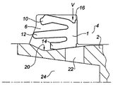
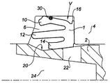
図1乃至図4は、ブレーキマスターシリンダの本体4内で軸線方向に摺動するピストン2を取り囲む環状シール1を示す。
環状シール1は、ブレーキマスターシリンダの本体4の環状ハウジング6に取り付けられており、外側リップ部10と、内側リップ部14とを備えている。外側リップ部10の端部は、静的シールを提供するため、このハウジングの円筒形の外壁に半径方向に、押し付けられている(すなわち、圧接されている)。内側リップ部14の端部は、ピストン2の外面に半径方向に押し付けられており、このピストンの摺動時に動的シールを提供する。
1 to 4 show an annular seal 1 surrounding a
The annular seal 1 is attached to the
環状シール1は、実質的に平らな後面を備えており、環状シール1の平らな後面は、環状ハウジング6の、半径方向に延びる平らな後面に押し付けられる。
環状シール1は、更に、外側リップ部10と内側リップ部14との間の半径方向中間に、軸線方向に延びるリップ部12を備えている。このリップ部12は、実質的に軸線方向に差し向けられており(すなわち、案内されており)、このリップ部12の端部は、ハウジングの前面及び後面の二つの面の間でこのシールが軸線方向で楔の作用をなすように、環状ハウジング6の実質的に半径方向に延びる前面に押し付けられている。
The annular seal 1 has a substantially flat rear surface, and the flat rear surface of the annular seal 1 is pressed against the radially extending flat rear surface of the
The annular seal 1 further includes a
環状シール1は、半径方向外方に延びる小さな半径方向リップ部16を更に備えている。このリップ部16は、環状シール1の後面を延長し、環状ハウジング6の後面に押し付けられる。かくして、ハウジング6の円筒形の外壁の下に、外側リップ部10と半径方向リップ部16との間に小さな容積Vが形成される。
The annular seal 1 further comprises a small
半径方向リップ部16は、外側リップ部10の作用を補助するように作用する。これは、半径方向リップ部16を第2シーリング障壁として直列に配置して、環状シール1と本体4との間の静的シールを強化するためである。
The
ピストン2が後休止位置にあるとき、内側リップ部14はピストン2の溝20内に落ち込んでいる。この溝は浅く、その側壁が小さな角度で傾斜している。この溝20の後壁には、半径方向に延びる穿孔(例えば、ドリル穴)22が形成されている。この穿孔は、第1に、内側リップ部14の後側に対して開放しており、第2にマスターシリンダの圧力チャンバ24内に開放している。
When the
かくして、半径方向穿孔22は、運転者がブレーキペダルを離し、この図に示す休止位置にある場合、液圧回路内のレベルを調節するため、圧力チャンバ24を液体のリザーバと連通する。
Thus, the
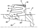
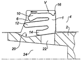
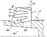
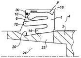
本発明による環状シール1の作動方法を図2、図3、及び図4に示す。制動時にピストン2が前方への移動を開始したとき、図2に示すように、環状シール1の内側リップ部14は、溝20の後方の傾斜に沿って摺動し、徐々に半径方向外方に持ち上がる。
The method of operating the annular seal 1 according to the present invention is shown in FIGS. When the
この持ち上がり移動により、環状シール1の弾性材料が半径方向外方に圧縮され、これにより、液体で充填された小さな容積Vが圧縮される。この容積V内の液体の圧縮により、第1に、半径方向リップ部16が環状ハウジング6の後壁に更にしっかりと押し付けられ、第2に、ほぼ所定の圧力で又はこの圧力を越えたとき、外側リップ部10が移動でき、かくして、図3に示すように、この容積が少なくとも部分的に空になる。
This lifting movement compresses the elastic material of the annular seal 1 radially outward, thereby compressing the small volume V filled with liquid. Due to the compression of the liquid in this volume V, firstly, the
ひとたびこの容積が少なくとも部分的に空になった後、その内部の圧力が低下し、
逆止弁と同様に作動する外側リップ部10が、図4に示すように、ハウジングの底部に再び押し付けられ、容積Vを再び閉鎖する。
Once this volume is at least partially emptied, its internal pressure drops,
An
制動の終了時に、ペダルがその休止位置に戻るに従って、内側リップ部14が溝20に再び落ち込み、シールの材料内の圧力が減少し、容積Vが再び増大し、内部圧力が減少し、これにより、半径方向リップ部16が移動する。この半径方向リップ部の移動によって、液体が容積V内に吸い込まれ、容積Vが再び充填される。
At the end of braking, as the pedal returns to its rest position, the
かくして各制動サイクルで、少量の流体の移動が発生し、この流体が容積Vから前方に連続的に押しやられ、後方から吸引される。
図5及び図6は、環状シール1の外側リップ部10の下に入り込んで引っ掛かった粒子30に流体のこの移動が及ぼす効果を示す。
Thus, in each braking cycle, a small amount of fluid movement occurs and this fluid is continuously pushed forward from the volume V and sucked from the rear.
FIGS. 5 and 6 illustrate the effect of this movement of fluid on the
容積Vが空になるとき、液体が粒子30をその前方への移動に従って搬送する。各制動サイクル時に外側リップ部10とハウジングの底部との間の接触領域を系統的にクリーニングできる。このことは、半径方向リップ部16についてもいえることであり、流体が通過する効果によりクリーニングが行われる。
When the volume V is empty, the liquid carries the
動的シールを提供する内側リップ部14に関し、各制動サイクルでのピストン2の移動がこのリップ部上での摺動に影響を及ぼし、常に粒子の除去を行う。
かくして、ブレーキ流体に粒子が懸濁している場合でも、長期に亘り良好なシールが経済的に得られることが保証される。
With respect to the
Thus, it is ensured that a good seal is obtained economically over a long period of time, even when particles are suspended in the brake fluid.
1 環状シール
2 ピストン
4 ブレーキマスターシリンダ本体
6 環状ハウジング
10 外側リップ部
12 軸線方向リップ部
14 内側リップ部
16 半径方向リップ部
20 溝
22 半径方向穿孔(半径方向ドリル穴)
24 圧力チャンバ
V 容積部
1
24 Pressure chamber V Volume
Claims (6)
本体(4)内で軸線方向に摺動するピストン(2)を備え、このピストンは、前記本体(4)のハウジング(6)に配置された環状シール(1)と協働しており、
前記環状シール(1)は、
前記ピストンを取り囲み、また、前記ピストンが後休止位置にある場合に前記ピストンの環状溝(20)に嵌着する動的な封止用の内側リップ部(14)と、
前記ハウジングの壁に押し付けられる静的な封止用の外側リップ部(10)とを備えた、マスターシリンダにおいて、
前記環状シール(1)は、追加の静的な封止用のリップ部(16)を備え、この静的な封止用のリップ部(16)は、当該環状シールの前記ハウジングの半径方向に沿った壁に押し付けられ、前記外側リップ部とともに液体の小さな閉鎖容積(V)を形成する、ことを特徴とするマスターシリンダ。 In particular, a master cylinder for hydraulic brake circuits for automobiles,
Comprising a piston (2) sliding axially within the body (4), which piston cooperates with an annular seal (1) arranged in the housing (6) of the body (4);
The annular seal (1)
An inner lip (14) for dynamic sealing that surrounds the piston and fits into the annular groove (20) of the piston when the piston is in a rest position;
A master cylinder with a static sealing outer lip (10) pressed against the housing wall;
The annular seal (1) is provided with an additional static sealing lip (16), the static sealing lip (16) in the radial direction of the housing of the annular seal. A master cylinder, characterized in that it is pressed against a wall along which it forms a small closed volume (V) of liquid with said outer lip.
前記ピストン(2)がその後休止位置から離れるとき、前記内側リップ部(14)は前記環状溝(20)から離れ、
前記環状シール(1)は、前記小さな容積(V)を圧縮して前記液体をこの容積の外に押し出すための手段を備える、ことを特徴とするマスターシリンダ。 The master cylinder according to claim 1,
When the piston (2) subsequently leaves the rest position, the inner lip (14) leaves the annular groove (20);
Master cylinder according to claim 1, characterized in that the annular seal (1) comprises means for compressing the small volume (V) and forcing the liquid out of this volume.
前記外側リップ部(10)は、前記小さな容積(V)内の圧力が上昇した場合に開放する逆止弁を形成するように、僅かな傾斜により前記ハウジングの前記壁に押し付けられた状態で位置決めされる、ことを特徴とするマスターシリンダ。 The master cylinder according to claim 2,
The outer lip (10) is positioned in a state of being pressed against the wall of the housing by a slight inclination so as to form a check valve that opens when the pressure in the small volume (V) increases. A master cylinder characterized by being made.
前記追加のリップ部(16)は、僅かな傾斜により前記ハウジングの壁に押し付けられた状態で位置決めされており、前記小さな容積(V)内の圧力が低下した場合に開放する逆止弁を形成する、ことを特徴とするマスターシリンダ。 In the master cylinder according to claim 2 or 3,
The additional lip portion (16) is positioned while pressed against the wall of the housing by a slight inclination to form a check valve that opens when the pressure in the small volume (V) drops. A master cylinder characterized by that.
前記外側リップ部(10)は、実質的に軸線方向に延びており、前記ハウジング(6)の円筒形の半径方向外面に押し付けられており、
前記追加のリップ部(16)は、実質的に半径方向に延びており、このハウジングの、半径方向に延びる平らな後面に押し付けられている、ことを特徴とするマスターシリンダ。 In the master cylinder according to claim 3 or 4,
The outer lip (10) extends substantially axially and is pressed against the cylindrical radially outer surface of the housing (6);
Master cylinder according to claim 1, characterized in that the additional lip (16) extends substantially radially and is pressed against a flat rear surface of the housing extending radially.
前記環状シール(1)は、前記外側リップ部(10)と前記内側リップ部(14)との間の半径方向中間に軸線方向リップ部(12)を備え、
この軸線方向リップ部(12)は、実質的に軸線方向に差し向けられており、その端部は、前記環状ハウジング(6)の実質的に半径方向に延びる前面に押し付けられている、ことを特徴とするマスターシリンダ。 In the master cylinder according to any one of claims 1 to 5,
The annular seal (1) comprises an axial lip (12) in the radial middle between the outer lip (10) and the inner lip (14),
The axial lip (12) is oriented substantially axially and its end is pressed against a substantially radially extending front surface of the annular housing (6). Characteristic master cylinder.
Applications Claiming Priority (2)
| Application Number | Priority Date | Filing Date | Title |
|---|---|---|---|
| FR0807186 | 2008-12-19 | ||
| FR0807186A FR2940222B1 (en) | 2008-12-19 | 2008-12-19 | BRAKE CYLINDER MASTER JOINT, FOR MOTOR VEHICLE |
Publications (2)
| Publication Number | Publication Date |
|---|---|
| JP2010143571A true JP2010143571A (en) | 2010-07-01 |
| JP5349276B2 JP5349276B2 (en) | 2013-11-20 |
Family
ID=41213169
Family Applications (1)
| Application Number | Title | Priority Date | Filing Date |
|---|---|---|---|
| JP2009286241A Active JP5349276B2 (en) | 2008-12-19 | 2009-12-17 | Master cylinder seal for automobile brakes |
Country Status (5)
| Country | Link |
|---|---|
| US (1) | US8567788B2 (en) |
| EP (1) | EP2199164B1 (en) |
| JP (1) | JP5349276B2 (en) |
| CN (1) | CN101746367B (en) |
| FR (1) | FR2940222B1 (en) |
Cited By (1)
| Publication number | Priority date | Publication date | Assignee | Title |
|---|---|---|---|---|
| JP2014151768A (en) * | 2013-02-08 | 2014-08-25 | Nissin Kogyo Co Ltd | Vehicular hydraulic master cylinder |
Families Citing this family (12)
| Publication number | Priority date | Publication date | Assignee | Title |
|---|---|---|---|---|
| JP5201648B2 (en) * | 2006-10-31 | 2013-06-05 | ボッシュ株式会社 | Cup seal and master cylinder using the same |
| FR2969089B1 (en) * | 2010-12-21 | 2012-12-28 | Bosch Gmbh Robert | BRAKING SYSTEM MASTER CYLINDER SEAL SEAL |
| FR2969084B1 (en) | 2010-12-21 | 2013-05-10 | Bosch Gmbh Robert | TANDEM MASTER CYLINDER SECONDARY PISTON AND MASTER CYLINDER EQUIPPED WITH SUCH A SECONDARY PISTON |
| FR2969085B1 (en) | 2010-12-21 | 2013-04-12 | Bosch Gmbh Robert | PLASTIC PRIMARY PISTON WITH INSERT FOR MASTER-CYLINDER TANDEM WITH PENETRATION AND MASTER-CYLINDER PROVIDED WITH SUCH A PISTON |
| US9611712B2 (en) * | 2012-02-09 | 2017-04-04 | Onesubsea Ip Uk Limited | Lip seal |
| CN104220311B (en) * | 2012-05-31 | 2016-06-29 | 日立汽车系统株式会社 | main tank |
| WO2014119611A1 (en) * | 2013-01-31 | 2014-08-07 | 日立オートモティブシステムズ株式会社 | Master cylinder |
| DE102013111057A1 (en) * | 2013-10-07 | 2015-04-23 | Endress + Hauser Conducta Gesellschaft für Mess- und Regeltechnik mbH + Co. KG | Sealing system and retractable fitting comprising such |
| EP3215770B1 (en) * | 2014-11-07 | 2020-02-26 | Dayco IP Holdings, LLC | Check valve with improved sealing member |
| FR3046820B1 (en) * | 2016-01-15 | 2018-02-16 | Valeo Embrayages | HYDRAULIC CYLINDER TRANSMITTER WITH IMPROVED SEALING DEVICE |
| JP6833021B2 (en) * | 2017-05-11 | 2021-02-24 | 株式会社バルカー | Seal structure |
| FR3070741B1 (en) * | 2017-09-01 | 2019-10-18 | Aetc Sapphire | ANNULAR JOINT FOR IMPLEMENTING ROTATING SEAL BETWEEN TWO CYLINDRICAL ELEMENTS |
Citations (6)
| Publication number | Priority date | Publication date | Assignee | Title |
|---|---|---|---|---|
| JPS58138863U (en) * | 1982-03-15 | 1983-09-19 | アイシン精機株式会社 | ring-shaped rubber cup |
| JPH0296257U (en) * | 1988-10-28 | 1990-07-31 | ||
| JP2000108878A (en) * | 1998-09-30 | 2000-04-18 | Tokico Ltd | Master cylinder |
| JP2006273293A (en) * | 2005-03-30 | 2006-10-12 | Hitachi Ltd | Master cylinder |
| JP2007091214A (en) * | 2005-09-26 | 2007-04-12 | Robert Bosch Gmbh | Car master cylinder |
| JP2008111495A (en) * | 2006-10-31 | 2008-05-15 | Bosch Corp | Cup seal and master cylinder using the same |
Family Cites Families (19)
| Publication number | Priority date | Publication date | Assignee | Title |
|---|---|---|---|---|
| US4326379A (en) * | 1979-11-06 | 1982-04-27 | Societe Anonyme Francaise Du Ferodo | Hydraulic control device for a motor vehicle braking circuit |
| US4781024A (en) * | 1985-03-07 | 1988-11-01 | Aisin Seiki Kabushiki Kaisha | Static cup seal assembly for master cylinder end |
| FR2741922B1 (en) | 1995-12-05 | 1998-01-09 | Valeo | METHOD FOR ASSEMBLING A DRIVE CYLINDER FOR A HYDRAULIC DRIVE DEVICE OF A MOTOR VEHICLE CLUTCH |
| JP4286548B2 (en) | 2003-01-31 | 2009-07-01 | 株式会社日立製作所 | Master cylinder |
| WO2004094208A1 (en) * | 2003-04-23 | 2004-11-04 | Bosch Corporation | Plunger-type master cylinder |
| DE102004014867A1 (en) * | 2003-08-18 | 2005-11-24 | Continental Teves Ag & Co. Ohg | Cylinders, in particular for hydraulic motor vehicle brake systems |
| JP4645097B2 (en) * | 2003-12-01 | 2011-03-09 | 株式会社アドヴィックス | Master cylinder |
| JP4388838B2 (en) * | 2004-03-23 | 2009-12-24 | ボッシュ株式会社 | Cup seal and master cylinder using the same |
| JP4417233B2 (en) * | 2004-09-30 | 2010-02-17 | 日立オートモティブシステムズ株式会社 | Master cylinder |
| JP4493567B2 (en) | 2005-08-31 | 2010-06-30 | 日信工業株式会社 | Lip-shaped seal member and vehicle hydraulic master cylinder using the lip-shaped seal member |
| US7487638B2 (en) * | 2006-06-09 | 2009-02-10 | Shimano Inc. | Bicycle hydraulic brake accentuate device |
| DE102006040487B3 (en) * | 2006-08-30 | 2007-11-08 | Lucas Automotive Gmbh | Sealing ring for piston in brake cylinder fits into annular groove in cylinder wall and has sealing lip on its back of the ring which fits against piston, spacer nearer outside edge of ring projecting beyond it |
| KR20090055624A (en) * | 2006-10-23 | 2009-06-02 | 봇슈 가부시키가이샤 | Cup seal and master cylinder using it |
| CN201015990Y (en) * | 2006-12-14 | 2008-02-06 | 吉林汽车制动器厂 | Novel plunger type main leather cup for the brake master cylinder |
| FR2916405B1 (en) * | 2007-05-21 | 2009-07-10 | Bosch Gmbh Robert | MASTER CYLINDER COMPRISING A SEAL PROMOTING REALIMENTATION. |
| FR2916406B1 (en) * | 2007-05-22 | 2009-07-10 | Bosch Gmbh Robert | MASTER CYLINDER COMPRISING A JOINT AND AN ASSOCIATED THROAT ENHANCING THE REALIMENTATION. |
| JP5112784B2 (en) * | 2007-08-10 | 2013-01-09 | ボッシュ株式会社 | Cup seal and master cylinder using the same |
| KR100979956B1 (en) * | 2008-08-22 | 2010-09-06 | 주식회사 만도 | Sealing member for master cylinder and master cylinder with same |
| FR2940221B1 (en) * | 2008-12-19 | 2011-10-21 | Bosch Gmbh Robert | MASTER CYLINDER LEVER SEAL OF A BRAKING CIRCUIT. |
-
2008
- 2008-12-19 FR FR0807186A patent/FR2940222B1/en not_active Expired - Fee Related
-
2009
- 2009-12-01 EP EP09177659.1A patent/EP2199164B1/en active Active
- 2009-12-17 JP JP2009286241A patent/JP5349276B2/en active Active
- 2009-12-17 US US12/640,821 patent/US8567788B2/en active Active
- 2009-12-18 CN CN2009102624846A patent/CN101746367B/en active Active
Patent Citations (6)
| Publication number | Priority date | Publication date | Assignee | Title |
|---|---|---|---|---|
| JPS58138863U (en) * | 1982-03-15 | 1983-09-19 | アイシン精機株式会社 | ring-shaped rubber cup |
| JPH0296257U (en) * | 1988-10-28 | 1990-07-31 | ||
| JP2000108878A (en) * | 1998-09-30 | 2000-04-18 | Tokico Ltd | Master cylinder |
| JP2006273293A (en) * | 2005-03-30 | 2006-10-12 | Hitachi Ltd | Master cylinder |
| JP2007091214A (en) * | 2005-09-26 | 2007-04-12 | Robert Bosch Gmbh | Car master cylinder |
| JP2008111495A (en) * | 2006-10-31 | 2008-05-15 | Bosch Corp | Cup seal and master cylinder using the same |
Cited By (1)
| Publication number | Priority date | Publication date | Assignee | Title |
|---|---|---|---|---|
| JP2014151768A (en) * | 2013-02-08 | 2014-08-25 | Nissin Kogyo Co Ltd | Vehicular hydraulic master cylinder |
Also Published As
| Publication number | Publication date |
|---|---|
| CN101746367A (en) | 2010-06-23 |
| US8567788B2 (en) | 2013-10-29 |
| FR2940222A1 (en) | 2010-06-25 |
| US20100156052A1 (en) | 2010-06-24 |
| JP5349276B2 (en) | 2013-11-20 |
| FR2940222B1 (en) | 2010-12-24 |
| EP2199164A1 (en) | 2010-06-23 |
| CN101746367B (en) | 2013-12-04 |
| EP2199164B1 (en) | 2013-05-22 |
Similar Documents
| Publication | Publication Date | Title |
|---|---|---|
| JP5349276B2 (en) | Master cylinder seal for automobile brakes | |
| JPH10266971A (en) | Piston pump | |
| JP2000108878A5 (en) | ||
| USRE40573E1 (en) | Master cylinder | |
| US9102310B2 (en) | Hydraulic unit | |
| JP3867498B2 (en) | Check valve and ABS actuator using the check valve | |
| JP2001508854A (en) | Piston pump | |
| FR2859436A1 (en) | HYDRAULIC BRAKE SYSTEM AND METHOD FOR CONTROLLING THE SAME | |
| KR20170019655A (en) | Caliper brake | |
| KR102657659B1 (en) | valve device | |
| JP4233457B2 (en) | Electric hydraulic brake circuit for vehicles | |
| US6065279A (en) | Master cylinder | |
| JP2012229020A (en) | Brake device | |
| CN102416936B (en) | Fast-fill tandem master cylinder | |
| CN105539406A (en) | Master cylinder for brake system | |
| KR200286155Y1 (en) | High pressure accumulator of vehicle anti-lock brake system | |
| KR20070062255A (en) | Master cylinder | |
| JP3576379B2 (en) | Reservoir for brake fluid pressure control device | |
| FR2989046A1 (en) | MASTER CYLINDER PISTON | |
| EP1350702A1 (en) | Master cylinder with reduced operational noise | |
| JP2000205143A (en) | Plunger type hydraulic pump | |
| JPS6220065B2 (en) | ||
| FR2917040A1 (en) | Brake caliper piston backward movement limiting device for motor vehicle, has valves automatically closed when positive pressure falls, such that pressure is not negative to eliminate aspiration problems and backward movement of pistons | |
| JPS5939099Y2 (en) | Brake master cylinder device | |
| JPH0347961Y2 (en) |
Legal Events
| Date | Code | Title | Description |
|---|---|---|---|
| A621 | Written request for application examination |
Free format text: JAPANESE INTERMEDIATE CODE: A621 Effective date: 20111201 |
|
| A977 | Report on retrieval |
Free format text: JAPANESE INTERMEDIATE CODE: A971007 Effective date: 20121212 |
|
| A131 | Notification of reasons for refusal |
Free format text: JAPANESE INTERMEDIATE CODE: A131 Effective date: 20121217 |
|
| A601 | Written request for extension of time |
Free format text: JAPANESE INTERMEDIATE CODE: A601 Effective date: 20130315 |
|
| A602 | Written permission of extension of time |
Free format text: JAPANESE INTERMEDIATE CODE: A602 Effective date: 20130321 |
|
| RD04 | Notification of resignation of power of attorney |
Free format text: JAPANESE INTERMEDIATE CODE: A7424 Effective date: 20130521 |
|
| A521 | Request for written amendment filed |
Free format text: JAPANESE INTERMEDIATE CODE: A523 Effective date: 20130614 |
|
| TRDD | Decision of grant or rejection written | ||
| A01 | Written decision to grant a patent or to grant a registration (utility model) |
Free format text: JAPANESE INTERMEDIATE CODE: A01 Effective date: 20130722 |
|
| A61 | First payment of annual fees (during grant procedure) |
Free format text: JAPANESE INTERMEDIATE CODE: A61 Effective date: 20130820 |
|
| R150 | Certificate of patent or registration of utility model |
Ref document number: 5349276 Country of ref document: JP Free format text: JAPANESE INTERMEDIATE CODE: R150 Free format text: JAPANESE INTERMEDIATE CODE: R150 |
|
| R250 | Receipt of annual fees |
Free format text: JAPANESE INTERMEDIATE CODE: R250 |
|
| R250 | Receipt of annual fees |
Free format text: JAPANESE INTERMEDIATE CODE: R250 |
|
| R250 | Receipt of annual fees |
Free format text: JAPANESE INTERMEDIATE CODE: R250 |
|
| R250 | Receipt of annual fees |
Free format text: JAPANESE INTERMEDIATE CODE: R250 |
|
| R250 | Receipt of annual fees |
Free format text: JAPANESE INTERMEDIATE CODE: R250 |
|
| R250 | Receipt of annual fees |
Free format text: JAPANESE INTERMEDIATE CODE: R250 |
|
| R250 | Receipt of annual fees |
Free format text: JAPANESE INTERMEDIATE CODE: R250 |
|
| R250 | Receipt of annual fees |
Free format text: JAPANESE INTERMEDIATE CODE: R250 |
|
| R250 | Receipt of annual fees |
Free format text: JAPANESE INTERMEDIATE CODE: R250 |
|
| R250 | Receipt of annual fees |
Free format text: JAPANESE INTERMEDIATE CODE: R250 |