JP2010143550A - Seat device for vehicle - Google Patents
Seat device for vehicle Download PDFInfo
- Publication number
- JP2010143550A JP2010143550A JP2008326336A JP2008326336A JP2010143550A JP 2010143550 A JP2010143550 A JP 2010143550A JP 2008326336 A JP2008326336 A JP 2008326336A JP 2008326336 A JP2008326336 A JP 2008326336A JP 2010143550 A JP2010143550 A JP 2010143550A
- Authority
- JP
- Japan
- Prior art keywords
- seat
- armrest
- armrest body
- driver
- parking brake
- Prior art date
- Legal status (The legal status is an assumption and is not a legal conclusion. Google has not performed a legal analysis and makes no representation as to the accuracy of the status listed.)
- Abandoned
Links
- 230000037431 insertion Effects 0.000 description 10
- 238000003780 insertion Methods 0.000 description 10
- 230000002452 interceptive effect Effects 0.000 description 5
- 230000008878 coupling Effects 0.000 description 3
- 238000010168 coupling process Methods 0.000 description 3
- 238000005859 coupling reaction Methods 0.000 description 3
- 230000000149 penetrating effect Effects 0.000 description 3
- 239000004744 fabric Substances 0.000 description 2
- 230000037237 body shape Effects 0.000 description 1
- 238000006243 chemical reaction Methods 0.000 description 1
- 238000006073 displacement reaction Methods 0.000 description 1
- 230000000694 effects Effects 0.000 description 1
- 230000000414 obstructive effect Effects 0.000 description 1
- 230000001105 regulatory effect Effects 0.000 description 1
- 230000000284 resting effect Effects 0.000 description 1
- 238000009751 slip forming Methods 0.000 description 1
- 238000003466 welding Methods 0.000 description 1
Images


Landscapes
- Seats For Vehicles (AREA)
Abstract
Description
本発明は、車両のシート装置に関し、特に、運転席と助手席との間にアームレストを備えたシート装置に関する。 The present invention relates to a vehicle seat device, and more particularly to a seat device including an armrest between a driver seat and a passenger seat.
従来、自動車には運転席に着座する運転者用にアームレストを有するものがある。この運転者用のアームレストは、運転席とは別体でフロアパネルに固定されたものと、運転席のシートバックに設けられたものがある。また、運転席と助手席との間にはパーキングブレーキ等を備えたセンターコンソールが設けられたものがある。車室内が比較的狭いコンパクトカーでは、前記アームレストが運転席のシートバックに取り付けられる場合が多い。ここで、アームレストが運転席のシートバックに取り付けられるものでは、シートバックと一体にアームレストが移動する。そのため、シートバックを前方にスライドさせると、アームレストがセンターコンソールに設けられたパーキングブレーキ上に位置してアームレストがパーキングブレーキの操作の邪魔になるという問題がある。 Conventionally, some automobiles have an armrest for a driver sitting in a driver's seat. There are two types of driver armrests, one that is separate from the driver's seat and fixed to the floor panel, and the other that is provided on the seat back of the driver's seat. In addition, there is a center console provided with a parking brake or the like between the driver seat and the passenger seat. In a compact car with a relatively small passenger compartment, the armrest is often attached to the seat back of the driver's seat. Here, when the armrest is attached to the seat back of the driver's seat, the arm rest moves integrally with the seat back. Therefore, when the seat back is slid forward, there is a problem that the armrest is positioned on the parking brake provided on the center console and the armrest interferes with the operation of the parking brake.
これに対して、例えば、特許文献1には、使用位置にてアームレストとパーキングブレーキとを離間させることでパーキングブレーキの操作性を確保したシート装置が開示されている。すなわち、特許文献1のシート装置では、アームレスト本体をシートバックの側部に沿って立設する格納位置と水平方向に延びる位置との間で回動自在に支持するとともに、このアームレスト本体を車幅方向に摺動可能に支持する支持軸が設けられている。そして、この支持軸の回動と摺動とによって、アームレスト本体が前記格納位置から運転席側に変位しつつ回動して使用状態において運転席のシートクッションと重なる位置に配置されることで、パーキングブレーキとアームレスト本体とが離間し、これによりパーキングブレーキの操作性が確保される。
前記特許文献1に開示されている装置では、使用状態にてアームレスト本体が運転席のシートクッションと重なる位置に配置されているため、アームレスト本体が運転者の胸を圧迫してハンドル操作等をし難くする場合がある。
In the device disclosed in
本発明は、このような事情に鑑み、快適な運転操作を維持しつつパーキングブレーキの操作性を確保するシート装置の提供を目的とする。 In view of such circumstances, an object of the present invention is to provide a seat device that ensures operability of a parking brake while maintaining a comfortable driving operation.
前記課題を解決するために、本発明は、車両の底面を形成するフロアパネルと、当該フロアパネルの上方に配置された運転席と、当該運転席の側部に配置された助手席と、前記運転席と助手席との間に配置されたパーキングブレーキとを備えた車両のシート装置であって、前記運転席は、前記フロアパネルに車両前後方向にスライド可能に支持されたシートクッションと当該シートクッションの後部に配置されたシートバックと当該シートバックの前記助手席側の側部に配置されたアームレストとを備え、前記アームレストは、乗員の腕が載置されるアームレスト本体を、前記シートバックの側部に沿って立設する格納位置と前記パーキングブレーキが設けられたセンターコンソール上に倒伏する使用位置との間で鉛直方向に回動可能に支持する第1回動軸と、前記アームレスト本体を、前記使用位置と前記パーキングブレーキから水平方向に離間する位置との間で水平方向に回動可能に支持する第2回動軸とを備えることを特徴とする車両のシート装置を提供する(請求項1)。 In order to solve the above problems, the present invention provides a floor panel that forms a bottom surface of a vehicle, a driver seat that is disposed above the floor panel, a passenger seat that is disposed on a side portion of the driver seat, A vehicle seat device including a parking brake disposed between a driver seat and a passenger seat, wherein the driver seat is supported by the floor panel so as to be slidable in the vehicle front-rear direction and the seat A seat back disposed at a rear portion of a cushion and an armrest disposed on a side portion of the seat back on the passenger seat side, wherein the armrest includes an armrest body on which an occupant's arm is placed, It is supported so as to be able to rotate in the vertical direction between a storage position standing along the side and a use position lying on the center console where the parking brake is provided. A first rotation shaft, and a second rotation shaft that supports the armrest body so as to be rotatable in a horizontal direction between the use position and a position spaced apart from the parking brake in the horizontal direction. A vehicle seat device is provided (claim 1).
この装置によれば、アームレスト使用時における運転席の着座スペースを確保しアームレストと運転者との干渉を抑制して快適なハンドル操作等を維持しつつパーキングブレーキの操作性を確保することができる。 According to this device, it is possible to secure the operability of the parking brake while maintaining a comfortable steering wheel operation and the like by securing a seating space for the driver's seat when using the armrest and suppressing interference between the armrest and the driver.
すなわち、この装置では、アームレストを使用する際には、アームレスト本体を前記運転席のシートバックの側部の格納位置から前記第1回動軸を中心として鉛直方向に回動させることで、このアームレスト本体を、センターコンソール上に倒伏した位置であって運転席のシートクッションとの重なりが小さく抑えられた使用位置に配置することができる。一方、パーキングブレーキを使用する際には、運転者の腕等の押動により、アームレスト本体を前記使用位置から前記第2回動軸を中心として水平方向に回動させることでアームレスト本体とパーキングブレーキとを容易に離間させることができ、パーキングブレーキの操作時にアームレストが邪魔にならず操作性を向上することができる。 That is, in this apparatus, when the armrest is used, the armrest body is rotated in the vertical direction around the first rotation axis from the storage position of the side portion of the seat back of the driver's seat. The main body can be disposed at a use position where the main body is lying down on the center console and the overlap with the seat cushion of the driver's seat is kept small. On the other hand, when the parking brake is used, the armrest body and the parking brake are rotated by rotating the armrest body horizontally from the use position around the second rotation axis by pushing the driver's arm or the like. Can be easily separated from each other, and the armrest does not get in the way when the parking brake is operated, thereby improving the operability.
また、前記アームレスト本体は、前記使用位置に配置された状態において、このアームレスト本体の前記運転席側の側面および底面とを連続して形成された運転席側凹部を有するのが好ましい(請求項2)。 In addition, the armrest body preferably has a driver seat side recess formed continuously with a side surface and a bottom surface of the armrest body on the driver seat side in a state where the armrest body is disposed at the use position. ).
このようにすれば、前記運転席側凹部を介してパーキングブレーキを操作することで、アームレストによりパーキングブレーキの操作が妨げられるのがより一層確実に抑制される。そして、パーキングブレーキを操作するために運転者が腕等によってアームレスト本体を押動しこのアームレスト本体を水平方向へ回動させる量を小さく抑えることができ、アームレスト本体の回動時に、アームレスト本体と助手席の乗員との干渉を抑制することができる。 In this way, by operating the parking brake via the driver side recess, it is more reliably suppressed that the operation of the parking brake is prevented by the armrest. Then, the driver can push the armrest body with his arm or the like to operate the parking brake, and the amount of rotation of the armrest body in the horizontal direction can be kept small. When the armrest body is rotated, the armrest body and assistant Interference with passengers in the seat can be suppressed.
また、前記アームレスト本体は、前記使用位置に配置された状態において、このアームレスト本体の前記助手席側の側面および底面とを連続して形成された助手席側凹部を有するのが好ましい(請求項3)。 In addition, the armrest body preferably has a passenger seat side recess formed continuously with a side surface and a bottom surface of the armrest body on the passenger seat side when the armrest body is disposed at the use position. ).
このようにすれば、特に、運転者が前記アームレスト本体の上方に手を回して前記パーキングブレーキを操作する場合に、前記助手席側凹部を介してパーキングブレーキを操作することで、アームレストが邪魔になるのを抑制することができる。 In this way, in particular, when the driver turns the hand above the armrest body and operates the parking brake, the armrest is obstructed by operating the parking brake via the recess on the passenger seat side. It can be suppressed.
また、前記アームレストは、前記アームレストが前記第2回動軸を中心として回動した際に、このアームレスト本体が平面視で前記助手席のシートクッションと重なる位置まで回動するのを規制する助手席側回動規制部を有するのが好ましい(請求項4)。 The armrest restricts the armrest body from rotating to a position overlapping the seat cushion of the passenger seat in a plan view when the armrest rotates about the second rotation axis. It is preferable to have a side rotation restricting portion (claim 4).
このようにすれば、アームレスト本体が回動した際にこのアームレスト本体と助手席の乗員との干渉を抑制することができる。 If it does in this way, when an armrest main part rotates, interference with this armrest main part and the passenger | crew of a passenger seat can be suppressed.
また、前記アームレストは、前記アームレストが前記第2回動軸を中心として回動した際に、このアームレスト本体が平面視で前記運転席のシートクッションと重なる位置まで回動するのを規制する運転席側回動規制部を有するのが好ましい(請求項5)。 The armrest is a driver seat that restricts the armrest body from rotating to a position overlapping the seat cushion of the driver seat in a plan view when the armrest rotates about the second rotation axis. It is preferable to have a side rotation restricting portion (claim 5).
このようにすれば、アームレスト本体が回動した際にこのアームレスト本体が運転席の乗員との干渉を抑制することができる。 If it does in this way, when an armrest main part rotates, this armrest main part can suppress interference with the passenger | crew of a driver's seat.
また、前記パーキングブレーキは、車幅方向において前記運転席と助手席との中間位置よりも前記運転席側あるいは助手席側にオフセットした位置に設けられているのが好ましい(請求項6)。 Further, the parking brake is preferably provided at a position offset to the driver seat side or the passenger seat side with respect to the intermediate position between the driver seat and the passenger seat in the vehicle width direction.
このようにすれば、アームレスト本体をパーキングブレーキから離間させるためにこのアームレスト本体を運転席の側部から回動させる量を小さくすることができ、運転者あるいは助手席の乗員との干渉が抑制される。例えば、前記パーキングブレーキが運転席に近接した位置に設けられている場合には、このアームレスト本体を助手席側に回動させる量を小さくすることができる。また、前記パーキングブレーキが助手席に近接した位置に設けられている場合には、このアームレスト本体を運転席側に回動させる量を小さくすることができる。 In this way, it is possible to reduce the amount by which the armrest body is rotated from the side of the driver's seat in order to move the armrest body away from the parking brake, and interference with the driver or passenger in the passenger seat is suppressed. The For example, when the parking brake is provided at a position close to the driver's seat, the amount by which the armrest body is rotated toward the passenger seat can be reduced. Further, when the parking brake is provided at a position close to the passenger seat, the amount by which the armrest body is rotated toward the driver seat can be reduced.
また、前記アームレストは、前記アームレスト本体が前記使用位置にある状態でこのアームレスト本体に上方から荷重が加えられた場合に、このアームレスト本体の前記第2回動軸を中心とする水平方向への回動を規制する水平方向回動規制部を有するのが好ましい(請求項7)。 The armrest rotates in a horizontal direction around the second rotation axis of the armrest body when a load is applied to the armrest body from above while the armrest body is in the use position. It is preferable to have a horizontal rotation restricting portion for restricting movement (claim 7).
このようにすれば、アームレスト本体の使用時にアームレスト本体の水平方向への移動が規制されるため、アームレスト本体に腕等を安定して載置することができる。 In this way, since the movement of the armrest body in the horizontal direction is restricted when the armrest body is used, an arm or the like can be stably placed on the armrest body.
以上のように、本発明によれば、アームレスト使用時における運転者の着座スペースを確保しつつ、パーキングブレーキの操作時にアームレストが邪魔になるのを抑制することのできるシート装置を提供することができる。 As described above, according to the present invention, it is possible to provide a seat device that can prevent the armrest from interfering when the parking brake is operated while securing a seating space for the driver when the armrest is used. .
本発明の好ましい実施形態について図面を参照しながら説明する。 A preferred embodiment of the present invention will be described with reference to the drawings.
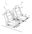
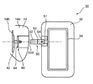
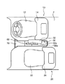
図1〜図5は、本発明に係る車両のシート装置1の実施形態を示している。このシート装置1は、車両の底面を形成するフロアパネル2と、このフロアパネル2の上方に配置された運転席10と、運転席10の側部に配置された助手席20と、運転席10と助手席20との間に配置されたパーキングブレーキ60とを備えている。
1 to 5 show an embodiment of a
前記運転席10は、シートクッション12と、シートバック14と、アームレスト30とを有している。前記シートクッション12は、前記フロアパネル2上に車両前後方向にスライド可能に支持されており、着座する乗員の体形等に応じて適切な位置に配置される。前記シートバック14は、前記シートクッション12の後部に連結されており、前記シートクッション12と一体に前後方向にスライド移動する。前記アームレスト30は、前記シートバック14の車幅方向の側部のうち前記助手席20側の側部14aに取り付けられており、このシートバック14とともに前記シートクッション12と一体に前後方向にスライド移動する。
The
前記助手席20も、前記運転席10と同様にシートクッション22とシートバック24とを有している。
The
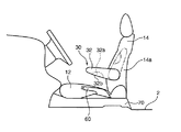
前記パーキングブレーキ60は、手動式であり運転者等の手によって上下に操作される。このパーキングブレーキ60は、前記運転席10と助手席20との間のフロアパネル2上に設けられたセンターコンソール70に固定されている。本実施形態では、このパーキングブレーキ60は、運転席10と助手席20との中間位置よりも運転席10側にオフセットした位置に設けられている。
The
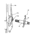
前記アームレスト30は、図6等に示すように、アームレスト本体32と、第1回動部40と、第2回動部50とを有している。
As shown in FIG. 6 and the like, the
前記アームレスト本体32は、前記運転席10に着座する乗員すなわち運転者の腕が載置される部分であり、略直方形状を有している。このアームレスト本体32は、前記第1回動部40によって、前記運転席10のシートバック14の側部14aに対して、図2の鎖線で示すようなこのシートバック14の側部14aに沿って立設する格納位置と、図2の実線で示すようなこのシートバック14の側部14aから前方に延びて前記センターコンソール70上に倒伏する使用位置との間で鉛直方向に回動可能に支持されている。また、前記アームレスト本体32は、前記第2回動部40によって、前記運転席10のシートバック14の側部14aに対して、水平方向に回動可能に支持されている。このアームレスト本体32は、前記使用位置に配置された状態で、その上面に前記運転者の腕が載置される。
The
図3等に示すように、前記使用位置に配置された状態において、前記アームレスト本体32の下方には、前記センターコンソール70上に固定されたパーキングブレーキ60が位置しており、アームレスト本体32とパーキングブレーキ60とは平面視で重なり合う。そのため、この使用位置に配置された状態では、運転者が前記パーキングブレーキ60を操作する際に、アームレスト本体32がその操作の邪魔になる場合がある。なお、前記パーキングブレーキ60は、前記センターコンソール70の前側部分に設けられている。そのため、運転者が小柄であって運転席10のシートバック14が車両前方にスライドされそれに伴って前記アームレスト30が前方にスライドした状態において、前記アームレスト本体32と前記パーキングブレーキ60との重なり合う領域は最大となり、アームレスト本体32が運転者のパーキングブレーキ操作の邪魔になる可能性は高くなる。
As shown in FIG. 3 and the like, a
これに対して、本シート装置1では、前述のように、前記アームレスト本体32が前記第2回動部40によって水平方向に回動可能に支持されており、アームレスト本体32が前記パーキングブレーキ60から離間する方向に水平方向に回動することで、このアームレスト本体32がパーキングブレーキ操作の妨げとなるのが回避される。
On the other hand, in the
すなわち、前記アームレスト本体32は、運転者の腕等により助手席20側に押圧されると、アームレスト本体32の後部に連結された後述する第2回動軸54を中心として、図4の鎖線で示す前記使用位置から、図4の実線で示すように前記助手席20側に水平方向に回動する。この状態において、アームレスト本体32は、前方に向かうほど助手席20側に傾き、その前側部分において、前記パーキングブレーキ60と平面視で重なり合う領域は小さくなる。その結果、運転者はアームレスト本体32に邪魔されることなくパーキングブレーキ60を容易に操作することが可能となる。ここで、前記図4の実線で示される状態において、前記アームレスト本体32の後端部32dは、前記運転席10のシートクッション14と干渉するが、本実施形態では、この後端部32dを変形容易な部材で構成しており、この後端部32dを変形させつつアームレスト本体32は回動する。
That is, when the
また、前記アームレスト本体32は、運転者の腕等により運転席10側に押圧されると、図5の鎖線で示す前記使用位置から、前記第2回動軸54を中心として、図5の実線で示すように前記運転席10側に水平方向に回動する。この状態においても、前記アームレスト本体32が前方に向かうほど運転席10側に傾き、アームレスト本体32の前側部分において前記パーキングブレーキ60とアームレスト本体32とが平面視で重なり合う領域が小さく抑えられる結果、運転者はアームレスト本体32に邪魔されることなくパーキングブレーキ60を容易に操作することが可能となる。
When the
前記アームレスト本体32の水平方向の回動範囲は、前記アームレスト本体32と前記助手席20のシートクッション22および前記運転席10のシートクッション12とが平面視で重ならない領域に設定されている。そのため、水平方向に回動した際に、アームレスト本体32が前記助手席20および運転席10側に突出する量は小さく、アームレスト本体32は、これら座席20,10に着座している乗員と干渉することなく回動する。ここで、前述のように、本実施形態では、前記パーキングブレーキ60は前記運転席10に近接する位置に設けられている。そのため、アームレスト本体32の助手席20側への回動量が小さくとも、前記アームレスト本体32を前記パーキングブレーキ60から十分に離間させることができる。
The horizontal rotation range of the
前記アームレスト本体32には、凹部32a(運転席側凹部)が設けられている。この凹部32aは、前記パーキングブレーキ60操作時に、アームレスト本体32がその操作の邪魔になるのを回避するためのものである。この凹部32aは、アームレスト本体32の運転席10側の側面32cと底面32bとを連続して形成されたものであって、アームレスト本体32が前記使用位置に配置された状態において、助手席20側に凹むとともに上方に凹む形状を有しており、前記運転席10に着座した運転者の肩と前記パーキングブレーキ60とを結ぶ領域を避けるように凹んでいる。従って、運転者はこの凹部32aに沿ってアームレスト本体32の下方に腕を挿入することで、アームレスト本体32に邪魔されることなく容易にパーキングブレーキ60を操作することができる。このように本シート装置1では凹部32aによってもアームレスト本体32がパーキングブレーキ操作の邪魔になるのが抑制されており、このアームレスト本体32が操作の邪魔となるを回避するためにアームレスト本体32を助手席20側へ回動する量は小さく抑えられている。そして、これにより、アームレスト本体32の助手席20への突出量を小さく抑えている。本実施形態では、前述のように、アームレスト本体32がパーキングブレーキ操作の邪魔になる可能性が高い運転者が小柄であって運転席10のシートバック14が車両前方にスライドされた状態において、この運転席10に着座する小柄な運転者の肩と前記パーキングブレーキ60とを結ぶ領域を避ける位置に前記凹部32aが設けられている。
The
次に、前記第1回動部40と第2回動部50の詳細構造について説明する。
Next, the detailed structure of the first
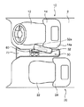
前記第1回動部40は、前述のように、前記運転席10のシートバック14の側部14aに対して、前記アームレスト本体32を鉛直方向に回動可能に支持するものである。この第1回動部40は、図7および図8に示すように、第1回動軸42と、第1回動ストッパ44とからなる。
As described above, the first rotating
前記第1回動軸42は、前記アームレスト本体32の鉛直方向の回動の回動中心となるものである。この第1回動軸42の一端は、前記シートバック14に水平方向に延びる状態で水平方向の軸を中心として回転可能に固定されている。より詳細には、前記第1回動軸42の一端は、前記シートバック14に内蔵されるシートバックフレーム14bのブラケット14cに形成された軸挿入孔14d内に回転可能に挿入固定されている。一方、この第1回動軸42の他端は前記第2回動部50に設けられる後述する嵌合孔52dに嵌合されており、この第2回動部50を介して前記アームレスト本体32に連結されている。従って、前記アームレスト本体32は、前記第1回動軸42の回転に伴って、この第1回動軸42を中心として鉛直方向に回動する。
The
前記第1回動ストッパ44は、この第1回動軸42ひいてはアームレスト本体32の鉛直方向の回動を所定の範囲に規制するためのものである。この第1回動ストッパ44は、前記第1回動軸42と一体に回動する。そして、この第1回動ストッパ44は、所定位置まで回動すると、前記シートバックフレーム14に設けられた図示しない当接部と当接してそれ以上の回動を禁止する。本実施形態では、前記アームレスト本体32が鉛直方向に延びる前記格納位置と、このアームレスト本体32が水平方向に延びる前記使用位置との間で回動するように規制する。
The
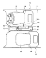
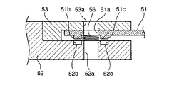
前記第2回動部50は、前述のように、前記運転席10のシートバック14の側部14aに対して、前記アームレスト本体32を水平方向に回動可能に支持するものである。この第2回動部50は、図9に示すように、第2回動軸54と、第1回動部側連結部52と、挟持部53と、前記第1回動部側連結部52及び挟持部53に挟持されるアームレスト側連結部51とを有している。
As described above, the second rotating
前記第2回動軸54は、前記アームレスト本体32の水平方向の回動の回動中心となるものである。この第2回動軸54は、ボルトおよびナットからなる。
The
前記第1回動部側連結部52は、前記第1回動部40と連結される部分である。この第1回動部側連結部52は、水平方向に延びる棒状部材である。より詳細には、この第1回動部側連結部52は、略半分が円柱形状を有しており、残り半分がこの円柱を中心軸を通る面で半分に切断したような半円形断面の柱状を有している。
The first rotating part
前記第1回動部側連結部52のうち前記円柱形状を有する部分には前記第1回動軸42の端部が挿入される嵌合孔52dが形成されている。この第1回動部側連結部52は、前記嵌合孔52dに前記第1回動軸42の端部が嵌合されることで、この第1回動軸42に、この第1回動軸42と一体に鉛直方向に回動可能に連結される。また、前記第1回動部側連結部52のうち半円形断面の柱状を有する部分には、前記第2回動軸54が挿通される上下に貫通する軸挿通孔52aが形成されている。
A
前記挟持部53は、前記第1回動部側連結部52との間で前記アームレスト側連結部51を挟持する部分である。この挟持部53は、前記第1回動部側連結部52のうち半円形断面の柱状を有する部分と対応して、略半円形断面の柱状を有している。この挟持部53には、前記第2回動軸54が挿通される上下に貫通する軸挿通孔53aが形成されている。
The clamping
前記アームレスト側連結部51は、前記アームレスト本体32と連結される部分である。このアームレスト側連結部51は、水平方向に延びる板状部材であり、その一端に前記アームレスト本体32に内蔵されるアームレストフレーム34が溶接等により固定されている。このアームレスト側連結部51には、前記第2回動軸54が挿通される上下に貫通する軸挿通孔51aが形成されている。
The armrest
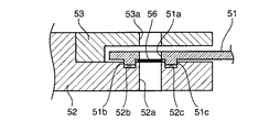
前記アームレスト側連結部51は、前記第1回動部側連結部52のうち半円形断面を有する部分の上面と前記挟持部53との間に、前記第2回動軸54を中心としてこれら第1回動部側連結部52および挟持部53に対して水平方向に回動可能に固定されている。より詳細には、前記第1回動部側連結部52に形成された軸挿通孔52aと前記アームレスト側連結部51に形成された軸挿通孔51aと前記挟持部53に形成された軸挿通孔53aとに前記第2回動軸54が挿通されることで、互いに一体に固定されている。ここで、前記第2回動軸54は、第1回動部側連結部52の軸挿通孔52aと挟持部53の軸挿通孔53aには締結される一方、前記アームレスト側連結部51の軸挿通孔51aに対しては単に挿通されているだけであり、アームレスト側連結部51は、前記第1回動部側連結部52と挟持部53との間で前記第2回動軸54を中心として水平方向に回動可能に支持される。そして、これにより、前記アームレスト本体32は、前記第1回動部側連結部52および前記第1回動軸42を介して前記シートバック14に対して水平方向に回動可能に支持される。
The armrest
以上のように構成された第2回動部50では、前記使用位置において運転者の腕等の押圧によりアームレスト本体32にこのアームレスト本体32を水平方向に回動させる力が加えられると、前記アームレスト側連結部51が前記第2回動軸54を中心として水平方向に回動しアームレストフレーム34ひいてはアームレスト本体32が回動する。ここで、前記アームレスト側連結部51と前記第1回動部側連結部52との間には、バネ56が圧縮された状態で取り付けられている。従って、前記アームレスト本体32は、このバネ56の反力に抗しつつ回動する一方、加えられた力が除去されることでバネ56の復元力により前記使用位置に復帰する。前記バネ56は、前記アームレスト側連結部51を前記挟持部53側に押し付けるように取付けられている。
In the second
前記第1回動部側連結部52のうち前記円柱形状を有する部分の上面には、上方に突出する第2回動ストッパ55(運転席側回動規制部、助手席側回動規制部)が固定されているとともに、下方に凹む2つの回動規制孔52b、52c(水平方向回動規制部)が形成されている。
A second rotation stopper 55 (driver seat side rotation restricting portion, passenger seat side turn restricting portion) protruding upward is formed on the upper surface of the cylindrical portion of the first turning portion
前記第2回動ストッパ55は、前記アームレスト側連結部51の前記第1回動部側連結部52に対する回動ひいてはこのアームレスト側連結部51に連結されるアームレスト本体32の水平方向の回動を所定の範囲に規制するためのものである。この第2回動ストッパ55は、前記アームレスト側連結部51が前記第1回動部側連結部52に対して所定位置まで回動した状態でこのアームレスト側連結部51と当接して、この当接によりアームレスト側連結部51がそれ以上回動するのを禁止する。本実施形態では、前述のように、アームレスト本体32が前記アームレスト本体32と前記助手席20のシートクッション22および前記運転席10のシートクッション12とが平面視で重ならない範囲で回動するように、前記アームレスト側連結部51の回動が規制される。
The
前記回動規制孔52b、52cは、前記アームレスト側連結部51の下面に形成された下方に突出する回動規制突起51b,51cと係合する部分である。
The
前記回動規制突起51b,51cは、前記アームレスト本体32の使用時に、前記アームレスト本体32が水平方向に回動するのを禁止するためのものである。これら回動規制突起51b,51cは、前記回動規制孔52b,52cと係合することで、この第1回動部側連結部52に対して前記アームレスト側連結部51の相対変位を禁止する。具体的には、前記アームレスト本体32に上方から力が加えられていない状態では、図10に示すように、前記バネ56の付勢力により前記アームレスト側連結部51は上方に位置しており、前記回動規制突起51b,51cと前記回動規制孔52b,52cとは離間している。そのため、前記アームレスト側連結部51は前記第1回動部側連結部52に対して回動することができる。これに対して、運転者の腕が載置されることで前記アームレスト本体32に上方から力が加えられると、図11に示すように、前記バネ56の付勢力に抗して前記アームレスト側連結部51が下方に変位する。そのため、前記回動規制突起51b,51cと前記回動規制孔52b,52cとが係合して、前記アームレスト側連結部51は前記第1回動部側連結部52に対して回動不可能となる。このようにして、前記アームレスト本体32に腕を載置した際にこのアームレスト本体32の水平方向への回動が禁止されれば、安定して腕を載置することができる。なお、前記アームレスト本体32に加えられた力が除去されると、前記アームレスト側連結部51ひいては前記アームレスト本体32は前記バネ56の付勢力により上方に復帰する。請求項における水平方向回動規制部は、この回動規制突起51b,51cと、回動規制孔52b,52cと、バネ56により構成される。
The
以上のようにして、本シート装置1では、前記第1回動部40および第2回動部50によって前記アームレスト本体32が、前記格納位置と前記使用位置との間で鉛直方向に回動可能に支持されるとともに、この使用位置から前記パーキングブレーキ60から離間する位置に水平方向に回動可能支持されることで、アームレスト本体32の使用時における運転席10の着座スペースを確保しつつパーキングブレーキ60操作時にアームレスト本体32が邪魔になるのを抑制してパーキングブレーキ60の操作性を確保することができる。
As described above, in the
ここで、図12および図13に示すように、前記パーキングブレーキ60は、運転席10と助手席20との中間位置よりも助手席20側にオフセットした位置に設けられていてもよい。このようにすれば、アームレスト本体32の上方に手を回してパーキングブレーキを操作する際等において、アームレスト本体32をパーキングブレーキ60から離間させるべくアームレスト本体32を運転席10側に回動させる量を小さくすることができ、アームレスト本体32の回動時における運転者の乗員とアームレスト本体32との干渉を抑制することができる。
Here, as shown in FIGS. 12 and 13, the
また、図12に示すように、前記凹部32aに代えて、あるいは加えて、アームレスト本体32の助手席20側の側面32eと底面32bとを連続して形成されたものであって、アームレスト本体32が前記使用位置に配置された状態において、運転席10側に凹むとともに下方に凹む形状を有する凹部(助手席側凹部)132aを形成してもよい。このようにすれば、この凹部132aに沿って前記アームレスト本体32の上方に手を回すことで、パーキングブレーキ操作時におけるアームレスト本体32による妨害が抑制され、パーキングブレーキ60を容易に操作することが可能となる。
Further, as shown in FIG. 12, instead of or in addition to the
また、前記凹部32aは省略可能である。ただし、凹部32aを設けておけば、パーキングブレーキ操作時にアームレスト本体32が邪魔になるのをより一層抑制することができる。そして、前記アームレスト本体32の水平方向の回動量を小さくすることができ、アームレスト本体32の運転席10あるいは助手席20への突出量を小さくすることができる。
The
また、前記凹部32aを弾性変位可能な布等で覆うようにしてもよい。このようにすれば、運転者の腕等の押圧によりこの布等を変形させることで前記凹部32aによるパーキングブレーキ60の操作性の向上効果を維持しつつ、アームレスト本体32が前記格納位置に配置された状態等において見栄えを向上させることができる。
Further, the
また、前記アームレスト本体32の回動範囲は前記に限らない。また、前記第2回動ストッパ55は省略可能である。ただし、このアームレスト本体32の回動範囲を、前記助手席20のシートクッション22および前記運転席10のシートクッション12と平面視で重ならない範囲とすれば、アームレスト本体32の運転席10あるいは助手席20の乗員との干渉を確実に抑制することができる。
The rotation range of the
また、前記回動規制突起51b,51cと前記回動規制孔52b,52cとバネ56で構成される水平方向回動規制部は省略可能である。ただし、この水平方向回動規制部を設けて、前記アームレスト本体32に上方から力が加えられた際にこのアームレスト本体32の水平方向の回動が規制されるよう構成すれば、アームレスト本体32の使用時にこのアームレスト本体32が水平方向にぐらつくのを抑制することができ使用感が向上する。
Moreover, the horizontal direction rotation control part comprised by the said
1 シート装置
2 フロアパネル
10 運転席
12 シートクッション
14 シートバック
20 助手席
22 シートクッション
30 アームレスト
32 アームレスト本体
32a 凹部
40 第1回動部
42 第1回動軸
50 第2回動部
51b,51c 回動規制突起(水平方向回動規制部)
52b,52c 回動規制孔(水平方向回動規制部)
54 第2回動軸
55 第2回動ストッパ(運転席側回動規制部、助手席側回動規制部)
56 バネ(水平方向回動規制部)
DESCRIPTION OF
52b, 52c rotation restriction hole (horizontal rotation restriction part)
54
56 Spring (horizontal rotation restricting part)
Claims (7)
前記運転席は、前記フロアパネルに車両前後方向にスライド可能に支持されたシートクッションと当該シートクッションの後部に配置されたシートバックと当該シートバックの前記助手席側の側部に配置されたアームレストとを備え、
前記アームレストは、乗員の腕が載置されるアームレスト本体を、前記シートバックの側部に沿って立設する格納位置と前記パーキングブレーキが設けられたセンターコンソール上に倒伏する使用位置との間で鉛直方向に回動可能に支持する第1回動軸と、前記アームレスト本体を、前記使用位置と前記パーキングブレーキから水平方向に離間する位置との間で水平方向に回動可能に支持する第2回動軸とを備えることを特徴とする車両のシート装置。 A floor panel forming a bottom surface of the vehicle, a driver seat disposed above the floor panel, a passenger seat disposed on a side of the driver seat, and the driver seat and the passenger seat are disposed between the driver seat and the passenger seat. A vehicle seat device including a parking brake,
The driver seat includes a seat cushion supported on the floor panel so as to be slidable in the vehicle front-rear direction, a seat back disposed at a rear portion of the seat cushion, and an armrest disposed on a side portion of the seat back on the passenger seat side. And
The armrest is located between a retracted position where an armrest body on which an occupant's arm is placed is erected along a side portion of the seat back and a use position where the armrest is lying on a center console provided with the parking brake. A first pivot shaft that pivotably supports in the vertical direction, and a second pivot that supports the armrest body so as to be pivotable in the horizontal direction between the use position and a position that is spaced apart from the parking brake in the horizontal direction. A vehicle seat device comprising a rotation shaft.
前記アームレスト本体は、前記使用位置に配置された状態において、このアームレスト本体の前記運転席側の側面および底面とを連続して形成された運転席側凹部を有することを特徴とする車両のシート装置。 The vehicle seat device according to claim 1,
The armrest body has a driver seat side recess formed continuously with a side surface and a bottom surface on the driver seat side of the armrest body in a state where the armrest body is disposed at the use position. .
前記アームレスト本体は、前記使用位置に配置された状態において、このアームレスト本体の前記助手席側の側面および底面とを連続して形成された助手席側凹部を有することを特徴とする車両のシート装置。 The vehicle seat device according to claim 1 or 2,
The vehicle seat device according to claim 1, wherein the armrest body includes a passenger seat side recess formed continuously with a side surface and a bottom surface of the armrest body on the passenger seat side when the armrest body is disposed at the use position. .
前記アームレストは、前記アームレスト本体が前記第2回動軸を中心として回動した際に、このアームレスト本体が前記助手席のシートクッションと平面視で重なる位置にまで回動するのを規制する助手席側回動規制部を有することを特徴とする車両のシート装置。 In the vehicle seat device according to any one of claims 1 to 3,
The armrest restricts the armrest body from rotating to a position overlapping the seat cushion of the passenger seat in plan view when the armrest body rotates about the second rotation axis. A vehicle seat device comprising a side rotation restricting portion.
前記アームレストは、前記アームレスト本体が前記第2回動軸を中心として回動した際に、このアームレスト本体が前記運転席のシートクッションと平面視で重なる位置にまで回動するのを規制する運転席側回動規制部を有することを特徴とする車両のシート装置。 In the vehicle seat device according to any one of claims 1 to 4,
The armrest restricts the armrest body from rotating to a position overlapping the seat cushion of the driver seat in a plan view when the armrest body rotates about the second rotation axis. A vehicle seat device comprising a side rotation restricting portion.
前記パーキングブレーキは、車幅方向において前記運転席と助手席との中間位置よりも前記運転席側あるいは助手席側にオフセットした位置に設けられていることを特徴とする車両のシート装置。 In the vehicle seat device according to any one of claims 1 to 5,
The vehicle seat device according to claim 1, wherein the parking brake is provided at a position offset in the vehicle width direction to the driver seat side or the passenger seat side from an intermediate position between the driver seat and the passenger seat.
前記アームレストは、前記アームレスト本体が前記使用位置にある状態でこのアームレスト本体に上方から荷重が加えられた場合に、このアームレスト本体の前記第2回動軸を中心とする水平方向への回動を規制する水平方向回動規制部を有することを特徴とする車両のシート装置。 In the vehicle seat device according to any one of claims 1 to 6,
When the armrest body is in the use position and a load is applied to the armrest body from above, the armrest rotates the armrest body in the horizontal direction around the second rotation shaft. A vehicle seat device comprising a horizontal rotation restricting portion for restricting.
Priority Applications (1)
| Application Number | Priority Date | Filing Date | Title |
|---|---|---|---|
| JP2008326336A JP2010143550A (en) | 2008-12-22 | 2008-12-22 | Seat device for vehicle |
Applications Claiming Priority (1)
| Application Number | Priority Date | Filing Date | Title |
|---|---|---|---|
| JP2008326336A JP2010143550A (en) | 2008-12-22 | 2008-12-22 | Seat device for vehicle |
Publications (1)
| Publication Number | Publication Date |
|---|---|
| JP2010143550A true JP2010143550A (en) | 2010-07-01 |
Family
ID=42564411
Family Applications (1)
| Application Number | Title | Priority Date | Filing Date |
|---|---|---|---|
| JP2008326336A Abandoned JP2010143550A (en) | 2008-12-22 | 2008-12-22 | Seat device for vehicle |
Country Status (1)
| Country | Link |
|---|---|
| JP (1) | JP2010143550A (en) |
Cited By (2)
| Publication number | Priority date | Publication date | Assignee | Title |
|---|---|---|---|---|
| JP2012136193A (en) * | 2010-12-27 | 2012-07-19 | Kanto Auto Works Ltd | Vehicle having parking brake lever and arm rest |
| WO2025061056A1 (en) * | 2023-09-18 | 2025-03-27 | 浙江极氪智能科技有限公司 | Seat apparatus and vehicle |
-
2008
- 2008-12-22 JP JP2008326336A patent/JP2010143550A/en not_active Abandoned
Cited By (2)
| Publication number | Priority date | Publication date | Assignee | Title |
|---|---|---|---|---|
| JP2012136193A (en) * | 2010-12-27 | 2012-07-19 | Kanto Auto Works Ltd | Vehicle having parking brake lever and arm rest |
| WO2025061056A1 (en) * | 2023-09-18 | 2025-03-27 | 浙江极氪智能科技有限公司 | Seat apparatus and vehicle |
Similar Documents
| Publication | Publication Date | Title |
|---|---|---|
| US7631930B2 (en) | Vehicle seat having an adjustable head restraint | |
| CN110053525B (en) | Vehicle seat | |
| JP3964172B2 (en) | Vehicle seat | |
| JP5276418B2 (en) | Slide seat device for vehicle | |
| JP5186850B2 (en) | Vehicle seat | |
| KR101731848B1 (en) | Seat frame of vehicles seat | |
| JP5381092B2 (en) | Vehicle seat device | |
| JP2009067351A (en) | Vehicular seat | |
| CN102001378B (en) | Backrest structure of motorcycle | |
| JP2010143550A (en) | Seat device for vehicle | |
| JP2009292403A (en) | Vehicle | |
| JPWO2014069067A1 (en) | Headrest lodging device and headrest | |
| JP4955352B2 (en) | Vehicle table | |
| JP2013141934A (en) | Foldable seat used for automobile | |
| JP6852630B2 (en) | Vehicle seat | |
| JP2016203692A (en) | In-cabin structure | |
| JP2019010902A (en) | Vehicle seat | |
| JP6595315B2 (en) | Vehicle seat | |
| JPH09109746A (en) | Seat device for vehicle | |
| JP7819029B2 (en) | Vehicle seats | |
| JP6808861B1 (en) | Vehicle seat | |
| JP3410300B2 (en) | Tilt lock mechanism for automotive seat cushion | |
| JP4380417B2 (en) | Vehicle seat device | |
| JP3210963U (en) | Vehicle cot | |
| JP5381077B2 (en) | Vehicle seat device |
Legal Events
| Date | Code | Title | Description |
|---|---|---|---|
| A621 | Written request for application examination |
Free format text: JAPANESE INTERMEDIATE CODE: A621 Effective date: 20111125 |
|
| A762 | Written abandonment of application |
Free format text: JAPANESE INTERMEDIATE CODE: A762 Effective date: 20121025 |