JP2010143391A - Direction indicator - Google Patents
Direction indicator Download PDFInfo
- Publication number
- JP2010143391A JP2010143391A JP2008322541A JP2008322541A JP2010143391A JP 2010143391 A JP2010143391 A JP 2010143391A JP 2008322541 A JP2008322541 A JP 2008322541A JP 2008322541 A JP2008322541 A JP 2008322541A JP 2010143391 A JP2010143391 A JP 2010143391A
- Authority
- JP
- Japan
- Prior art keywords
- turn
- auto
- lever
- switch
- cancel
- Prior art date
- Legal status (The legal status is an assumption and is not a legal conclusion. Google has not performed a legal analysis and makes no representation as to the accuracy of the status listed.)
- Pending
Links
- 230000007935 neutral effect Effects 0.000 claims abstract description 21
- 230000015607 signal release Effects 0.000 claims description 3
- 230000007246 mechanism Effects 0.000 abstract description 20
- 230000008859 change Effects 0.000 description 14
- 238000001514 detection method Methods 0.000 description 7
- 230000009471 action Effects 0.000 description 5
- 230000000694 effects Effects 0.000 description 3
- 238000000034 method Methods 0.000 description 3
- 230000008569 process Effects 0.000 description 3
- 238000007664 blowing Methods 0.000 description 2
- 238000010586 diagram Methods 0.000 description 2
- 230000008901 benefit Effects 0.000 description 1
- 239000004065 semiconductor Substances 0.000 description 1
Images
Classifications
-
- B—PERFORMING OPERATIONS; TRANSPORTING
- B60—VEHICLES IN GENERAL
- B60Q—ARRANGEMENT OF SIGNALLING OR LIGHTING DEVICES, THE MOUNTING OR SUPPORTING THEREOF OR CIRCUITS THEREFOR, FOR VEHICLES IN GENERAL
- B60Q1/00—Arrangement of optical signalling or lighting devices, the mounting or supporting thereof or circuits therefor
- B60Q1/26—Arrangement of optical signalling or lighting devices, the mounting or supporting thereof or circuits therefor the devices being primarily intended to indicate the vehicle, or parts thereof, or to give signals, to other traffic
- B60Q1/34—Arrangement of optical signalling or lighting devices, the mounting or supporting thereof or circuits therefor the devices being primarily intended to indicate the vehicle, or parts thereof, or to give signals, to other traffic for indicating change of drive direction
- B60Q1/40—Arrangement of optical signalling or lighting devices, the mounting or supporting thereof or circuits therefor the devices being primarily intended to indicate the vehicle, or parts thereof, or to give signals, to other traffic for indicating change of drive direction having mechanical, electric or electronic automatic return to inoperative position
- B60Q1/42—Arrangement of optical signalling or lighting devices, the mounting or supporting thereof or circuits therefor the devices being primarily intended to indicate the vehicle, or parts thereof, or to give signals, to other traffic for indicating change of drive direction having mechanical, electric or electronic automatic return to inoperative position having mechanical automatic return to inoperative position due to steering-wheel position, e.g. with roller wheel control
Landscapes
- Engineering & Computer Science (AREA)
- Mechanical Engineering (AREA)
- Lighting Device Outwards From Vehicle And Optical Signal (AREA)
Abstract
Description
本発明は、方向指示装置に関する。 The present invention relates to a direction indicating device.
従来、車両には、ステアリングホイールの近傍に設けられたターンレバーが操作されることにより車両の前後に設けられた方向指示ランプを点灯させることで、例えば右左折する際や隣接車線へ車線変更する際等に、運転者が意図する車両の進行方向を周囲に示す方向指示装置が設けられている。 Conventionally, when a turn lever provided in the vicinity of a steering wheel is operated on a vehicle, a direction indicator lamp provided at the front and rear of the vehicle is turned on, for example, when turning right or left or changing to a lane In some cases, a direction indicating device that indicates the traveling direction of the vehicle intended by the driver to the surroundings is provided.
方向指示装置は、ターンレバーが車両の進行方向に対応する方向へ操作されることによりその進行方向の方向指示ランプを作動させるターンスイッチと、ステアリングホイールがターンレバーの操作方向とは逆方向へ所定の角度以上回動されて元に戻った際にターンレバーを元の位置に復帰させ、方向指示を自動解除する解除機構とを備えている場合が多い。このような方向指示装置では、ターンレバーが車両の進行方向に対応する方向へ操作スイッチが作動すると、その進行方向の方向指示ランプが点灯する。そして、車両のターンが終了しステアリングホイールが直進位置に戻されると、解除機構によってターンレバーが元の位置に復帰し、方向指示ランプが消灯する。 The direction indicating device includes a turn switch that activates a direction indicating lamp in a traveling direction when the turn lever is operated in a direction corresponding to the traveling direction of the vehicle, and a steering wheel that has a predetermined direction opposite to the operating direction of the turn lever. In many cases, it is provided with a release mechanism that returns the turn lever to its original position when it returns to its original position after being rotated by an angle of the angle or more, and automatically releases the direction indication. In such a direction indicating device, when the operation switch is operated in a direction corresponding to the traveling direction of the vehicle, the direction indicating lamp in the traveling direction is turned on. When the turn of the vehicle is completed and the steering wheel is returned to the straight traveling position, the turn lever is returned to the original position by the release mechanism, and the direction indicator lamp is turned off.
一方、車両の操舵方向を知らせる方向指示ランプと、入力操作によって上記方向指示ランプを点灯させる方向指示手段と、点灯した方向指示ランプを消灯させる消灯手段と、を備え、上記消灯手段は、車両の操舵方向を検出し、操舵方向が方向指示手段で入力された方向と反対方向になったときに消灯信号を出力して方向指示ランプを消灯させる第1の消灯手段と、方向指示手段の入力から所定時間経過後に消灯信号を出力して方向指示ランプを消灯させる第2の消灯手段と、を備えた車両用方向指示装置が提案されている(特許文献1参照)。そして、このターンキャンセル制御がオートモードの方向指示手段は、ターンレバーの入力操作による左又は右への傾動後に中立状態に自動復帰する構造(モーメンタリスイッチ)とされている。 On the other hand, the vehicle includes a direction indication lamp that informs the steering direction of the vehicle, direction indication means that turns on the direction indication lamp by an input operation, and a turn-off means that turns off the lighted direction indication lamp. A first turn-off means for detecting a steering direction and outputting a turn-off signal to turn off the direction indication lamp when the steering direction is opposite to the direction input by the direction instruction means; There has been proposed a vehicular direction indicating device that includes a second extinguishing unit that outputs an extinguishing signal after a predetermined time has elapsed to extinguish a direction indicating lamp (see Patent Document 1). Then, the turn instruction control means in the auto mode has a structure (momentary switch) that automatically returns to the neutral state after tilting to the left or right by the input operation of the turn lever.
上記示した特許文献1の方向指示装置によれば、方向指示手段が自動復帰する構造とされているので、方向指示手段を手で復帰させる操作は不要であり、運転者の操作手間を省くことができ、走行操作を安全に行なえるとされている。
しかし、特許文献1の方向指示装置によると、すべての場合にオートモードによるターンキャンセル制御を行なおうとすると、最適なタイミングでターンキャンセルを行う必要がある。このため、走行先の道路状況や交通状況の情報を基に高度な制御を行う必要があり、高コストなシステムとなってしまうという問題がある。
However, according to the direction indicating device of
従って、本発明の目的は、方向指示装置がモーメンタリスイッチにより構成されている場合において、安価なシステムによりオートターンキャンセル機構を有する車両の方向指示装置を提供することにある。 Accordingly, an object of the present invention is to provide a vehicle direction indicating device having an auto turn canceling mechanism by an inexpensive system when the direction indicating device is constituted by a momentary switch.
[1]本発明は、揺動操作可能に支持され、前記揺動操作後に中立位置へ自動復帰するターンレバーと、前記ターンレバーの第1範囲での揺動操作により操作され、車両の走行方向を報知するターンシグナルを発生させ、前記ターンシグナルの自動解除を行なうオートターンキャンセルモードを設定するターンスイッチと、前記ターンレバーの第2範囲での揺動操作により操作され、前記ターンシグナルのマニュアル解除を行なうマニュアルモードを設定するマニュアルスイッチと、前記ターンスイッチ及び前記マニュアルスイッチの動作状態に基づき、前記ターンシグナルの解除制御を行なうターンシグナル制御部と、を有することを特徴とする方向指示装置を提供する。 [1] The present invention is supported by a swinging operation and is automatically operated to return to a neutral position after the swinging operation, and is operated by a swinging operation of the turn lever in a first range, so that the traveling direction of the vehicle The turn signal is generated by a turn switch for setting an auto turn cancel mode for automatically releasing the turn signal, and the turn signal is manually operated by swinging in the second range. There is provided a direction indication device comprising: a manual switch for setting a manual mode for performing a turn signal; and a turn signal control unit for performing a release signal release control based on an operation state of the turn switch and the manual switch. To do.
[2]前記ターンレバーは、前記中立位置から前記第1範囲を有し、さらに揺動操作を要する前記第2範囲を有することを特徴とする上記[1]に記載の方向指示装置であってもよい。 [2] The direction indicating device according to [1], wherein the turn lever has the first range from the neutral position and further has the second range that requires a swinging operation. Also good.
[3]また、前記第2範囲での揺動操作時に、前記マニュアルモードを操作者に認識させる報知部をさらに有することを特徴とする上記[1]に記載の方向指示装置であってもよい。 [3] The direction indication device according to [1] may further include a notifying unit that allows an operator to recognize the manual mode during a swing operation in the second range. .
本発明によれば、方向指示装置がモーメンタリスイッチにより構成されている場合において、安価なシステムによりオートターンキャンセル機構を有する車両の方向指示装置を提供することができる。 ADVANTAGE OF THE INVENTION According to this invention, when the direction indication apparatus is comprised with the momentary switch, the direction indication apparatus of the vehicle which has an auto turn cancellation mechanism with an inexpensive system can be provided.
(本発明の第1の実施の形態)
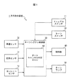
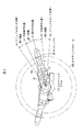
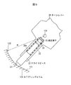
図1は、本発明の実施の形態に係る方向指示装置の概略ブロック構成図である。図2は、ステアリングホイールの裏側に装着されたターンレバーを示す運転者側から見た正面図である。図3はターンレバー20の内部に設けられた節度機構を示す部分断面図である。図4は方向指示装置の動作を示すフローチャートである。
(First embodiment of the present invention)
FIG. 1 is a schematic block diagram of a direction indicating device according to an embodiment of the present invention. FIG. 2 is a front view of the turn lever mounted on the back side of the steering wheel as seen from the driver side. FIG. 3 is a partial cross-sectional view showing a moderation mechanism provided inside the turn lever 20. FIG. 4 is a flowchart showing the operation of the direction indicating device.
本発明の実施の形態に係る方向指示装置1は、揺動操作可能に支持され、揺動操作後に中立位置へ自動復帰するターンレバー20と、ターンレバー20の第1範囲での揺動操作により操作され、車両の走行方向を報知するターンシグナルを発生させ、ターンシグナルの自動解除を行なうオートターンキャンセルモードを設定するターンスイッチ10と、ターンレバー20の第2範囲での揺動操作により操作され、ターンシグナルのマニュアル解除を行なうマニュアルモードを設定するマニュアルスイッチ11と、ターンスイッチ10及びマニュアルスイッチ11の動作状態に基づき、ターンシグナルの解除制御を行なうターンシグナル制御部30と、音、振動、又は、光等の手段により上記のマニュアルモード設定を報知する報知部40とを有して構成されている。
The
方向指示装置1は、車両の前後にそれぞれ設けられる左右一対のターンランプ50を点灯させることにより運転する車両の進行方向を他の車両の運転者等に知らせる方向指示動作を行うものである。
The
方向指示装置1は、図2に示すように、車両のステアリングコラム101に設けられるターンレバー20を通じて操作される。ターンレバー20は、運転者からみて図2において二点鎖線で示すステアリングホイール102の裏側に配置されている。ターンレバー20の基端部は、ステアリングコラム101の内部において回転可能に支持されており、ターンレバー20は、ステアリングコラム101の外部に突出している。ターンレバー20の基端部は、ステアリングコラム101に対してこの内部に配置されたターンレバー20の回転軸103を中心として、ステアリングホイール102の回転方向に沿った方向へ所定角度だけ揺動可能に支持されている。
As shown in FIG. 2, the
ターンレバー20は、その中心軸が図2に示される操作中立位置Cに保持されている。そして、ターンレバー20は、操作中立位置Cに保持された状態から反時計回り方向へ第1範囲を揺動操作されると、ターンレバー20の回転軸103を中心として左折操作位置Aまで揺動する。これにより、車両の前後にそれぞれ設けられた左側ターンランプ50が点灯する。この揺動操作による操作力が解除されると、図示しない復帰機構の作用により、ターンレバー20は操作中立位置Cへ自動復帰する。すなわち、ターンレバー20は、常に操作中立位置Cに復帰動作するモーメンタリタイプのレバーであるモーメンタリスイッチとして構成されている。ターンレバー20が操作中立位置Cに復帰した後においても、左側ターンランプ50の点灯表示は継続される。
The center axis of the turn lever 20 is held at the operation neutral position C shown in FIG. When the turn lever 20 is swung in the first range from the state held at the operation neutral position C in the counterclockwise direction, the turn lever 20 swings to the left turn operation position A about the
上記の第1範囲をターンレバー20が揺動操作されると、左折操作位置Aまで揺動された位置に設けられた図1に示すターンスイッチがONする。このターンスイッチの出力は、図1に示すように、ターンシグナル制御部30に入力され、ターンシグナルの自動解除を行なうオートターンキャンセルモードが設定される。
When the turn lever 20 is swung within the first range, the turn switch shown in FIG. 1 provided at the position swung to the left turn operation position A is turned ON. As shown in FIG. 1, the output of the turn switch is input to the turn
さらに、ターンレバー20が左折操作位置Aから反時計回り方向へ第2範囲を操作されると、マニュアルモード位置Dまで揺動する。このマニュアルモード位置Dまで揺動操作されると図1に示すマニュアルスイッチ11がONする。このマニュアルスイッチ11の出力は、図1に示すように、ターンシグナル制御部30に入力され、既に設定されたオートターンキャンセルモードを無効にする。このマニュアルモード位置Dまでの揺動操作による操作力が解除されると、図示しない復帰機構の作用により、ターンレバー20は操作中立位置Cへ自動復帰する。
Further, when the turn lever 20 is operated in the second range counterclockwise from the left turn operation position A, it swings to the manual mode position D. When the swing operation is performed up to the manual mode position D, the
また、同様に、ターンレバー20は、操作中立位置Cに保持された状態から時計回り方向へ第1範囲を揺動操作されると、ターンレバー20の回転軸103を中心として右折操作位置Bまで揺動する。これにより、車両の前後にそれぞれ設けられた右側ターンランプ50が点灯する。この揺動操作による操作力が解除されると、図示しない復帰機構の作用により、ターンレバー20は操作中立位置Cへ自動復帰する。ターンレバー20が操作中立位置Cに復帰した後においても、右側ターンランプ50の点灯表示は継続される。
Similarly, when the turn lever 20 is swung in the first range from the state held at the operation neutral position C in the clockwise direction, the turn lever 20 reaches the right turn operation position B about the
上記の第1範囲をターンレバー20が揺動操作されると、右折操作位置Bまで揺動された位置に設けられた図1に示すターンスイッチ10がONする。このターンスイッチ10の出力は、図1に示すように、ターンシグナル制御部30に入力され、ターンシグナルの自動解除を行なうオートターンキャンセルモードが設定される。
When the turn lever 20 is swung within the first range, the turn switch 10 shown in FIG. 1 provided at the position swung to the right turn operation position B is turned ON. As shown in FIG. 1, the output of the turn switch 10 is input to the turn
さらに、ターンレバー20が右折操作位置Bから時計回り方向へ第2範囲を操作されると、マニュアルモード位置Eまで揺動する。このマニュアルモード位置Eまで揺動操作されると図1に示すマニュアルスイッチ11がONする。このマニュアルスイッチ11の出力は、図1に示すように、ターンシグナル制御部30に入力され、既に設定されたオートターンキャンセルモードを無効にする。このマニュアルモード位置Eまでの揺動操作による操作力が解除されると、図示しない復帰機構の作用により、ターンレバー20は操作中立位置Cへ自動復帰する。
Further, when the turn lever 20 is operated in the second range in the clockwise direction from the right turn operation position B, it swings to the manual mode position E. When the swing operation is performed up to the manual mode position E, the
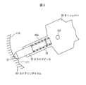
図3はターンレバー20の内部に設けられた節度機構を示す部分断面図である。ターンレバー20は、揺動操作可能に回転軸103を中心として回転可能に支持されている。ターンレバー20の内部には、先端に当接部21を有するスライドピース22とコイルバネ23が保持部20aにスライド可能に保持されることで節度機構が設けられている。ステアリングコラム101側には、節度機構の当接部21が当接する当接面110が形成され、この当接面110には、図2に示したマニュアルモード位置D、Eに対応する位置に、スライドピース22へ向って突出する突起部111が形成されている。
FIG. 3 is a partial cross-sectional view showing a moderation mechanism provided inside the turn lever 20. The turn lever 20 is supported to be rotatable about a
ターンレバー20を揺動操作すると、スライドピース22はコイルバネ23により当接部21と当接面110が略一定の当接圧で接触した状態で、図2に示す第1範囲、及び第2範囲内を移動する。第2範囲の終点付近、すなわち、マニュアルモード位置D、Eに対応する位置には、突起部111が形成されているので、スライドピース22が突起部111により押圧される。これにより、ターンレバー20を揺動操作する際に、マニュアルモード位置D、Eに対応する位置で節度感(クリック感)が発生する。但し、ターンレバー20は、突起部111により揺動操作がロックされることはなく、ターンレバー20の操作を止めれば図示しない復帰機構の作用により操作中立位置Cへ自動復帰する。
When the turn lever 20 is swung, the slide piece 22 is in a first range and a second range shown in FIG. 2 in a state where the
上記示したターンレバー20の揺動操作により、図2に示す左折操作位置A、右折操作位置Bに対応して設けられてスイッチ動作するターンスイッチ10は、図1に示すように、ターンシグナル制御部30に接続されている。また、図2に示すマニュアルモード位置D、マニュアルモード位置Eに対応して設けられてスイッチ動作するマニュアルスイッチ11は、ターンシグナル制御部30に接続されている。ターンシグナル制御部30は、ターンレバー20の左折操作または右折操作によるターンスイッチ10のスイッチ動作に基づいて、ターンシグナルとして左側ターンランプ、右側ターンランプ50を点灯制御するための制御ユニットを有する。
As shown in FIG. 1, the turn switch 10 provided in correspondence with the left turn operation position A and the right turn operation position B shown in FIG. Connected to the
ここで、ターンシグナル制御部30は、ターンスイッチ10及びマニュアルスイッチ11の動作状態に基づき、ターンシグナルの解除制御を行なう。ターンシグナル制御部30は、ターンレバー20の揺動操作によるターンシグナルの発生後、所定の条件を判断することによりターンシグナルの自動解除を行なうオートターンキャンセル判定ECU(Electric Control Unit)60を有している。このオートターンキャンセル判定ECU60には、車速センサ70、蛇舵角センサ71、及びヨーレートセンサ72が接続され、これらのセンサ出力に基づいて所定の条件を判断することによりターンシグナルの自動解除を行なうオートターンキャンセルモードが設定される。
Here, the turn
また、ターンシグナル制御部30は、マニュアルスイッチ11がONにされた場合、ターンレバー20の揺動操作によるターンシグナルの発生後、上記示したオートターンキャンセルモードを無効にして、ターンシグナルのマニュアル解除を行なうマニュアルモードに設定する。
Further, when the
車速センサ70は、運転する車両の走行速度を検出し、その検出した速度に応じた車速検出信号をターンシグナル制御部30へ出力する。
The
蛇舵角センサ71は、運転者によってステアリングホイール102が回転操作された際に、その回転角度である蛇舵角(操舵角)を検出し、その検出された蛇舵角に応じて蛇舵角検出信号をターンシグナル制御部30へ出力する。すなわち、蛇舵角センサ71は、ステアリングホイール102が蛇舵角中点(車両直進時の蛇舵角)を基準として左右いずれの方向へ回転操作されたのかを検出して、いずれの場合であっても蛇舵角中点を基準とする正の値の蛇舵角情報を蛇舵角検出信号として出力する。尚、この蛇舵角情報にはステアリングホイール102が左右いずれの方向へ操舵されたのかを示す操舵方向情報が含まれる。
The
ヨーレートセンサ72は、例えば運転する車両が右左折したり車線変更したりする際のヨーレート(車両の回転方向の挙動)を検出し、その検出したヨーレートに応じたヨーレート検出信号をターンシグナル制御部30へ出力する。
The
(報知部)
報知部40は、図1に示すように、ターンシグナル制御部30に接続されている。この報知部40は、マニュアルスイッチ11がONにされた場合に、オートターンキャンセル判定ECU60によるオートターンキャンセルモードが無効にされ、マニュアルモードが設定されたことを運転者等が容易に認識できるように、音、又は、光により報知するものである。
(Notification part)
The alerting | reporting
報知部40は、例えば、電子音、アナウンスによる音声を発するサウンド吹鳴部であり、また、LED、ランプ等の光を発する発光部である。これ以外でも、マニュアルモードが設定されたことを運転者等が容易に認識できる手段であればよく、例えば、振動、文字や図形等による表示であってもよい。
The
音、電子音、アナウンスによるサウンド吹鳴部としては、例えば、運転席側ドアに搭載されたスピーカであり、車載オーディオ装置に使用されるスピーカと共通化することも可能である。 The sound blowing unit by sound, electronic sound, or announcement is, for example, a speaker mounted on a driver's seat side door, and can be shared with a speaker used in an in-vehicle audio apparatus.
また、光による報知部40の例として、発光部を設けることもできる。発光部は、例えば、LED、ランプ等により構成され、運転者が容易に認識できる例えばAピラーに装着され、マニュアルモードが設定されたことを運転者等が容易に認識できるように報知する。
In addition, a light emitting unit may be provided as an example of the
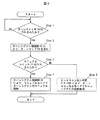
(方向指示装置の動作)
図4に示すフローチャートに従って方向指示装置の動作を説明する。車両が運転状態にある場合、オートターンキャンセル判定ECU60は、ターンスイッチ10がONされたかどうかを所定の時間間隔で常に監視している(Step1)。ターンスイッチ10がONされたと判断された場合は、Step2へ進み、ターンスイッチ10がONされたと判断されない場合は、Step1を繰り返す。
(Operation of direction indicator)
The operation of the direction indicating device will be described with reference to the flowchart shown in FIG. When the vehicle is in a driving state, the auto turn
ターンスイッチ10がONされたと判断された場合は、図2に示す左折操作位置A、右折操作位置Bに対応して、ターンシグナル制御部30が左側ターンランプ、右側ターンランプ50を点灯制御する(Step2)。また、ターンシグナルの自動解除を行なうオートターンキャンセルモードが設定される。
If it is determined that the turn switch 10 has been turned ON, the turn
ターンランプ50の点灯後、オートターンキャンセル判定ECU(Electric Control Unit)60は、マニュアルスイッチ11がONされたかどうかを判断する(Step3)。マニュアルスイッチ11がONされたと判断された場合は、Step4へ進み、マニュアルスイッチ11がONされたと判断されない場合は、Step5へ進む。
After the
マニュアルスイッチ11がONされたと判断された場合は、Step2で設定されたオートターンキャンセルモードが無効とされ、ターンシグナルのマニュアル解除を行なうマニュアルモードが設定される。このマニュアルモードでは、操作中立位置Cへ自動復帰しているターンレバー20を逆方向へ揺動操作することでターンシグナルのマニュアル解除を行なうことができる(Step4)。尚、ターンレバー20を再度同じ方向へ揺動操作することでターンシグナルのマニュアル解除を行なう設定とすることもできる。
When it is determined that the
例えば、ターンレバー20を図2に示す第1範囲を左折操作位置Aまで揺動操作して左側ターンランプ50が点灯表示され、さらに、ターンレバー20が左折操作位置Aから反時計回り方向へ第2範囲を操作されてマニュアルモード位置Dまで揺動操作されることによりマニュアルモードに設定された場合は、ターンレバー20を操作中立位置Cから右折操作位置Bまで揺動操作することにより、ターンシグナルのマニュアル解除を行なう。
For example, when the turn lever 20 is swung to the left turn operation position A in the first range shown in FIG. 2, the
また、キャンセル準備角θ1以上の操舵角が発生した後、操舵角がキャンセル角θ2以下となった場合に、ターンシグナルのマニュアル解除を行なう設定とすることができる。キャンセル準備角θ1は、操舵角の絶対値でのキャンセルを有効にするか無効にするかの判定角であり、キャンセル角θ2は、キャンセル準備角θ1を超えてステアリングを操作した後、戻してきた時にターンシグナルがOFFする角度である。 In addition, after the steering angle equal to or greater than the cancel preparation angle θ1 is generated, the turn signal can be manually canceled when the steering angle becomes equal to or smaller than the cancel angle θ2. The cancellation preparation angle θ1 is a determination angle for determining whether to cancel or cancel the absolute value of the steering angle. The cancellation angle θ2 is returned after operating the steering beyond the cancellation preparation angle θ1. The angle at which the turn signal sometimes turns off.
例えば、ターンレバー20が図2に示すマニュアルモード位置Dまで揺動操作されてマニュアルモードに設定された後、操舵角がキャンセル準備角θ1を超えるまでステアリング操作された後、逆方向へのステアリング操作により戻してきた時に、操舵角がキャンセル角θ2以下となった場合にターンシグナルのマニュアル解除を行なう。 For example, after the turn lever 20 is swung to the manual mode position D shown in FIG. 2 and set to the manual mode, the steering operation is performed until the steering angle exceeds the cancel preparation angle θ1, and then the steering operation in the reverse direction is performed. When the steering angle is returned to the above, the turn signal is manually canceled when the steering angle becomes equal to or smaller than the cancellation angle θ2.
また、マニュアルモードが設定された場合、運転者等が容易に認識できるように、音、又は、光により報知する。 Further, when the manual mode is set, notification is given by sound or light so that the driver can easily recognize it.
マニュアルスイッチ11がONされたと判断されない場合は、Step2で設定されたオートターンキャンセルモードが有効であり、ターンシグナルの自動解除が行なわれる(Step5)。
If it is not determined that the
(オートターンキャンセルモードによるターンシグナルの自動解除)
Step5のターンシグナルの自動解除は、以下に示すように行なわれる。ターンシグナル制御部30に設けられたオートターンキャンセル判定ECU60は、方向指示動作を開始したとき、開始した時点からの経過時間、車両の走行速度、蛇舵角及びヨーレート等から車両の走行状態を検出し、走行状態に基づいて、方向指示装置1の方向指示動作を終了する旨のオートターンキャンセルの判定を行う。そして、このオートターンキャンセル判定に基づいてターンランプ50の点灯による方向指示動作を自動的に終了する。
(Automatic cancellation of turn signal by auto turn cancel mode)
The automatic release of the turn signal at
オートターンキャンセル判定ECU60は、ターンランプ50の点灯後からの経過時間を内部に設けられたタイマによりカウントしていく。方向指示動作を開始してから、ステアリングホイール102の操作がなく、また、ある速度以上で車両が走行している状態で、通常想定される方向指示動作の継続時間を超える程度の一定時間が経過した場合、オートターンキャンセル判定ECU60は、方向指示動作を終了する条件(オートターンキャンセル条件)が成立したと判断し、オートターンキャンセルを行う旨のオートターンキャンセル判定を行う。ターンシグナル制御部30は、このオートターンキャンセル判定に基づいて、方向指示動作を終了する旨の信号を出力してターンランプ50への駆動電流の供給を停止して消灯する。
The auto turn cancel
また、オートターンキャンセル判定ECU60に接続されたROMには、キャンセル準備角θ1及びこのキャンセル準備角θ1よりも小さいキャンセル角θ2が記憶されている。オートターンキャンセル判定ECU60は、方向指示動作の開始後、蛇舵角センサ71を通じてステアリングホイール102の蛇舵角θの変化を検出する。そして、蛇舵角θがキャンセル準備角θ1に達した(θ>θ1)後にキャンセル角θ2の範囲内になった場合(θ<θ2)、オートターンキャンセル判定ECU60は、オートターンキャンセル条件が成立したと判断し、ターンランプ50の方向指示動作を終了する旨の判定を行う。これにより、例えば交差点等を右折または左折した後に直進状態に移行する場合のように、ターンランプ50の示す方向ヘステアリングホイール102がキャンセル準備角θ1に達した後にステアリングホイール102がキャンセル角θ2の範囲内に戻されると、蛇舵角θに基づいてオートターンキャンセル判定がなされて方向指示動作が自動終了される。
In addition, the ROM connected to the auto turn cancel
オートターンキャンセル判定ECU60は、ターンランプ50の点灯後から、ヨーレートセンサ72によるヨーレート検出信号に基づいてヨーレートの変化(車両の旋回方向への回転角度の単位時間当たりの変化量)を検出する。オートターンキャンセル判定ECU60のROMにはオートターンキャンセル判定の基準となる判定基準値が、車両の速度領域毎に記憶されている。通常、ヨーレートは、車両が右左折や車線変更等の進路変更を開始してから終了するまでの間に最大値及び最小値をそれぞれとるように変化する。オートターンキャンセル判定ECU60は、ヨーレートが最大値をとった後に判定基準値を下回った場合や、最小値をとった後に判定基準値を上回った場合、オートターンキャンセル条件が成立したと判断する。
The auto turn
また、オートターンキャンセル判定ECU60は、蛇舵角センサ71の蛇舵角検出信号に基づいて蛇舵角θの変化量を検出(算出)する。オートターンキャンセル判定ECU60のROMには、オートターンキャンセル判定を行うための判定基準となる判定基準値が、車両の速度領域毎に記憶されている。通常、蛇舵角θは、上記ヨーレートと同様、車両が進路変更を開始してから終了するまでの間に最大値及び最小値をとるように変化する。オートターンキャンセル判定ECU60は、蛇舵角θが最大値をとった後に判定基準値を下回った場合や、最小値をとった後に判定基準値を上回った場合、オートターンキャンセル条件が成立したと判断する。オートターンキャンセル判定ECU60は、ヨーレートに基づくオートターンキャンセル条件、及び蛇舵角θに基づくオートターンキャンセル条件の何れか一方が成立した場合、ターンランプ50の方向指示動作を終了する旨のオートターンキャンセル判定を行う。
Further, the auto-turn cancel
オートターンキャンセル判定ECU60は、ターンランプ50の点灯後から、ヨーレートセンサ72によるヨーレート検出信号に基づいてヨーレートの変化(車両の旋回方向への回転角度の単位時間当たりの変化量)を検出する。オートターンキャンセル判定ECU60のROMにはオートターンキャンセル判定の基準となる判定基準値が、車両の速度領域毎に記憶されている。通常、ヨーレートは、車両が右左折や車線変更等の進路変更を開始してから終了するまでの間に最大値及び最小値をそれぞれとるように変化する。ヨーレートは、車速、時間と共に車両の横方向移動距離算出に利用し、その移動距離が判断基準を上回った場合にオートターンキャンセル条件が成立したと判断する。
The auto turn
これにより、例えば隣接する車線へ車線変更する場合等のように、ターンランプ50の示す方向へのヨーレートの変化が小さい場合でも、舵角θの変化量ステアリングホイール102の蛇角θが小さくキャンセル準備角θ1に達しない場合でも、ヨーレートの変化に基づいてオートターンキャンセル判定がなされる。すなわち、上述したヨーレートの変化蛇角θに基づくオートターンキャンセル条件が成立しない場合でも、舵角θの変化量ヨーレートに基づくオートターンキャンセル条件が成立した場合、方向指示動作のオートターンキャンセル判定がなされ、交差点等の右左折時のみならず、例えば隣接する車線へ車線変更する場合でも、方向指示動作が自動終了される。
As a result, even when the change in the yaw rate in the direction indicated by the
(本発明の第1の実施の形態の効果)
本発明の実施の形態によれば、次のような効果を有する。
(1)方向指示装置1がモーメンタリスイッチにより構成されている場合において、安価なシステムによりオートターンキャンセル機構を構成できる。すなわち、ターンレバー20の揺動操作範囲に、マニュアルスイッチ11がONするマニュアルモード位置を設けることにより、ターンシグナルのマニュアル解除を行なうことができる。これにより、走行先の道路状況や交通状況の情報を基に高度な制御を行う必要がなく、安価なシステムによりオートターンキャンセル機構を実現できる。
(2)報知部40を有することにより、オートターンキャンセルモードが無効にされマニュアルモードが設定されたことを運転者等が容易に認識することができる。特に、ターンレバー20がモーメンタリスイッチである場合、ターンレバー20がマニュアルモード位置D、Eまで揺動操作されても操作中立位置Cへ自動復帰するので、報知部40によるマニュアルモードの報知は運転操作を助け、また、安全運転に効果を有する。
(3)安価なシステムにおいて、オートターンキャンセル制御をECUにて実施することにより、ターンレバー20をモーメンタリタイプとして操作の煩わしさを排除し、かつ、操作モードを選択可能として、ターンレバー20の操作性向上を図ることができる。
(Effects of the first embodiment of the present invention)
The embodiment of the present invention has the following effects.
(1) When the
(2) By having the
(3) In an inexpensive system, the automatic turn cancel control is performed by the ECU, so that the turn lever 20 is a momentary type, the operation troublesomeness is eliminated, and the operation mode can be selected. It is possible to improve the performance.
(本発明の第2の実施の形態)
図5は、連続的に操作感が変化する機構の例を示す部分断面図である。図3と同様に、ターンレバー20は、揺動操作可能に回転軸103を中心として回転可能に支持されている。ターンレバー20の内部には、先端に当接部21を有するスライドピース22とコイルバネ23が保持部20aにスライド可能に保持されている。保持部20aの奥部には、後述する当接面110から押圧されてスライド移動するスライドピース22、コイルバネ23、及び押圧子24を介して押圧される感圧素子25が配置されている。
(Second embodiment of the present invention)
FIG. 5 is a partial cross-sectional view showing an example of a mechanism that continuously changes the operational feeling. Similar to FIG. 3, the turn lever 20 is supported so as to be rotatable about the
ターンレバー20の回転軸103から、略一定の半径Rで当接部21が当接する当接面110が形成されている。この当接面110は、図2に示す第1範囲に対応して形成されている。また、当接面110は、図2に示す第2範囲に対応して、上記の半径Rが徐々に小さくなるように形成されている。従って、ターンレバー20を図2に示す第2範囲内でマニュアルモード位置DまたはEまで揺動操作すると、スライドピース22は回転軸103側へ押圧されてスライド移動する。
A
ターンレバー20が図2に示す第1範囲内で揺動操作される場合は、スライドピース22は回転軸103側へ押圧されずにスライド移動しない。従って、感圧素子25にかかる応力は一定値未満である。一方、ターンレバー20が図2に示す第2範囲内で揺動操作される場合は、スライドピース22は回転軸103側へ押圧されてスライド移動する。従って、ターンレバー20がマニュアルモード位置DまたはEまで揺動操作されると感圧素子25にかかる応力は増加して一定値以上となる。尚、感圧素子としては、半導体ダイヤフラム型、静電容量型、圧電型、等の公知の素子が使用可能である。
When the turn lever 20 is swung within the first range shown in FIG. 2, the slide piece 22 is not pushed toward the
以上示したターンレバー20の揺動操作において、感圧素子25にかかる応力が一定値未満の場合はオートターンキャンセルモードに設定し、感圧素子25にかかる応力が一定値以上の場合はマニュアルモードに設定することができる。これにより、ターンレバー20のマニュアルモード位置DまたはEの手前から感圧素子25に応力がかかる機構とすることができ、運転者の意思が反映できるシステムとすることができる。 In the swinging operation of the turn lever 20 described above, when the stress applied to the pressure sensitive element 25 is less than a certain value, the auto turn cancel mode is set, and when the stress applied to the pressure sensitive element 25 is greater than a certain value, the manual mode is set. Can be set to Thereby, it can be set as the mechanism in which the pressure-sensitive element 25 is stressed before the manual mode position D or E of the turn lever 20, and it can be set as the system which can reflect a driver | operator's intention.
尚、本発明は上記の実施の形態に限定されるものではなく、その要旨を逸脱しない範囲で種々の態様において実施することが可能である。例えば、オートターンキャンセルモードとマニュアルモードは、図2に示す第1範囲と第2範囲を逆に設定することもできる。また、本発明の実施の形態は、報知部40を有しない構成が可能である。また、ヨーレート情報は舵角センサ71で代用可能であるので、ヨーレートセンサ72を有しない構成が可能である。
In addition, this invention is not limited to said embodiment, It is possible to implement in a various aspect in the range which does not deviate from the summary. For example, in the auto turn cancel mode and the manual mode, the first range and the second range shown in FIG. 2 can be set in reverse. Further, the embodiment of the present invention can be configured without the
1…方向指示装置、10…ターンスイッチ、20…ターンレバー、21…当接部、22…スライドピース、23…コイルバネ、24…押圧子、25…感圧素子、30…ターンシグナル制御部、40…報知部、50…ターンランプ、60…オートターンキャンセル判定ECU、70…車速センサ、71…蛇舵角センサ、72…ヨーレートセンサ、101…ステアリングコラム、102…ステアリングホイール、103…回転軸、110…当接面、111…突起部
DESCRIPTION OF
Claims (3)
前記ターンレバーの第1範囲での揺動操作により操作され、車両の走行方向を報知するターンシグナルを発生させ、前記ターンシグナルの自動解除を行なうオートターンキャンセルモードを設定するターンスイッチと、
前記ターンレバーの第2範囲での揺動操作により操作され、前記ターンシグナルのマニュアル解除を行なうマニュアルモードを設定するマニュアルスイッチと、
前記ターンスイッチ及び前記マニュアルスイッチの動作状態に基づき、前記ターンシグナルの解除制御を行なうターンシグナル制御部と、
を有することを特徴とする方向指示装置。 A turn lever supported so as to be swingable and automatically returning to a neutral position after the swinging operation;
A turn switch that is operated by a swinging operation in the first range of the turn lever, generates a turn signal that informs the traveling direction of the vehicle, and sets an auto turn cancel mode that automatically cancels the turn signal;
A manual switch that is operated by a swinging operation of the turn lever in a second range and sets a manual mode for manually releasing the turn signal;
Based on the operating state of the turn switch and the manual switch, a turn signal control unit that performs release signal release control,
A direction indicating device characterized by comprising:
Priority Applications (3)
| Application Number | Priority Date | Filing Date | Title |
|---|---|---|---|
| JP2008322541A JP2010143391A (en) | 2008-12-18 | 2008-12-18 | Direction indicator |
| US12/639,974 US9041526B2 (en) | 2008-12-18 | 2009-12-16 | Directional indicator for a vehicle |
| CN2009102606890A CN101746310B (en) | 2008-12-18 | 2009-12-18 | Directional indicator |
Applications Claiming Priority (1)
| Application Number | Priority Date | Filing Date | Title |
|---|---|---|---|
| JP2008322541A JP2010143391A (en) | 2008-12-18 | 2008-12-18 | Direction indicator |
Publications (1)
| Publication Number | Publication Date |
|---|---|
| JP2010143391A true JP2010143391A (en) | 2010-07-01 |
Family
ID=42265172
Family Applications (1)
| Application Number | Title | Priority Date | Filing Date |
|---|---|---|---|
| JP2008322541A Pending JP2010143391A (en) | 2008-12-18 | 2008-12-18 | Direction indicator |
Country Status (3)
| Country | Link |
|---|---|
| US (1) | US9041526B2 (en) |
| JP (1) | JP2010143391A (en) |
| CN (1) | CN101746310B (en) |
Cited By (2)
| Publication number | Priority date | Publication date | Assignee | Title |
|---|---|---|---|---|
| JP2014073813A (en) * | 2012-10-05 | 2014-04-24 | Yazaki Corp | Turn cancel signal output device for vehicle |
| JP2018103767A (en) * | 2016-12-26 | 2018-07-05 | トヨタ自動車株式会社 | Vehicle lane change support device |
Families Citing this family (20)
| Publication number | Priority date | Publication date | Assignee | Title |
|---|---|---|---|---|
| DE102011004389A1 (en) * | 2011-02-18 | 2012-08-23 | Bayerische Motoren Werke Aktiengesellschaft | Vehicle with a selection device for selecting different states of a transmission |
| JP5965759B2 (en) * | 2012-07-13 | 2016-08-10 | 矢崎総業株式会社 | Direction indicator |
| JP5965761B2 (en) * | 2012-07-23 | 2016-08-10 | 矢崎総業株式会社 | Direction indicator |
| US9308856B2 (en) * | 2012-10-23 | 2016-04-12 | Tk Holdings, Inc. | Steering wheel light bar |
| DE102013215201A1 (en) * | 2013-08-02 | 2015-02-05 | Ford Global Technologies, Llc | Turn signal switch and method for resetting a turn signal switch |
| DE102014203854A1 (en) * | 2014-03-03 | 2015-09-03 | Conti Temic Microelectronic Gmbh | Automatic control of a direction indicator of a vehicle |
| JP5972332B2 (en) * | 2014-09-26 | 2016-08-17 | 本田技研工業株式会社 | Approach notification device for saddle riding type vehicles |
| KR101620209B1 (en) * | 2014-10-22 | 2016-05-13 | 현대자동차주식회사 | Apparatus for controlling turn signal |
| EP4086721B1 (en) * | 2015-03-11 | 2023-09-20 | Kubota Corporation | Work vehicle with a running control apparatus causing automatic running of the work vehicle, preferably an agricultural vehicle |
| DE102017011067B4 (en) * | 2017-11-30 | 2024-03-14 | Kostal Automobil Elektrik Gmbh & Co. Kg | Indicator switch for a motor vehicle |
| US10953791B2 (en) | 2018-03-08 | 2021-03-23 | Joyson Safety Systems Acquisition Llc | Vehicle illumination systems and methods |
| JP6722722B2 (en) * | 2018-06-26 | 2020-07-15 | 本田技研工業株式会社 | Vehicle driving support system |
| WO2020173543A1 (en) * | 2019-02-25 | 2020-09-03 | Volvo Truck Corporation | Computer-implemented method for automatically deactivating the left or right turn signals of a vehicle at the end of a turn |
| JP7671745B2 (en) | 2019-10-25 | 2025-05-02 | ジーエイチエスピー・インコーポレイテッド | Automatic release mechanism for turn signal light having axially operable toggle |
| DE102020208519A1 (en) * | 2020-07-07 | 2022-01-13 | Volkswagen Aktiengesellschaft | Method for adapting the duration of a turn signal of a vehicle |
| US11970179B2 (en) * | 2021-09-29 | 2024-04-30 | Zero Motorcycles, Inc. | Turn signal cancelation systems and methods for two-wheeled vehicles |
| CN115520089A (en) * | 2022-04-29 | 2022-12-27 | 谢伦帅 | Intelligent steering switch device and steering method thereof |
| JP2024168479A (en) * | 2023-05-24 | 2024-12-05 | ヤマハ発動機株式会社 | Saddle-type vehicle |
| EP4559752A1 (en) | 2023-11-24 | 2025-05-28 | Volvo Truck Corporation | Automatic turn signal cancellation in a vehicle for a roundabout |
| EP4559753A1 (en) | 2023-11-24 | 2025-05-28 | Volvo Truck Corporation | Dynamically-controlled automatic turn signal cancellation in a vehicle |
Family Cites Families (11)
| Publication number | Priority date | Publication date | Assignee | Title |
|---|---|---|---|---|
| IT223286Z2 (en) | 1991-09-17 | 1995-06-21 | Fiat Auto Spa | DEVIO-GUIDO STEERING WHEEL FOR A VEHICLE, IN PARTICULAR FOR VEHICLES. |
| DE4428369C2 (en) * | 1994-08-11 | 1996-07-18 | Deere & Co | Direction indicators |
| DE19758288B4 (en) | 1997-12-31 | 2006-10-26 | Valeo Schalter Und Sensoren Gmbh | Method and device for the rotationally-coupled reset of a switch |
| US6884986B2 (en) * | 1999-03-19 | 2005-04-26 | Dee Enterprises, Llc | Vehicle signal control module and system |
| JP2000355246A (en) | 1999-06-15 | 2000-12-26 | Nippon Yusoki Co Ltd | Vehicular turn signal lamp |
| JP4139027B2 (en) * | 1999-11-18 | 2008-08-27 | 株式会社東海理化電機製作所 | Turn signal canceling device |
| JP3866022B2 (en) | 2000-07-31 | 2007-01-10 | アルプス電気株式会社 | Operating device |
| US6876300B2 (en) * | 2002-11-25 | 2005-04-05 | Richard L. Ponziani | Electronic intelligent turn signal control system |
| JP4181024B2 (en) | 2003-12-08 | 2008-11-12 | 株式会社東海理化電機製作所 | Vehicle direction indication device |
| DE102005032847A1 (en) * | 2005-07-14 | 2007-01-25 | Robert Bosch Gmbh | Flasher switch for a motor vehicle having an adaptive cruise control |
| CN201165213Y (en) * | 2008-01-11 | 2008-12-17 | 深圳市赛格导航科技股份有限公司 | Automatic control system of automobile steering indicating light |
-
2008
- 2008-12-18 JP JP2008322541A patent/JP2010143391A/en active Pending
-
2009
- 2009-12-16 US US12/639,974 patent/US9041526B2/en not_active Expired - Fee Related
- 2009-12-18 CN CN2009102606890A patent/CN101746310B/en not_active Expired - Fee Related
Cited By (3)
| Publication number | Priority date | Publication date | Assignee | Title |
|---|---|---|---|---|
| JP2014073813A (en) * | 2012-10-05 | 2014-04-24 | Yazaki Corp | Turn cancel signal output device for vehicle |
| US10279731B2 (en) | 2012-10-05 | 2019-05-07 | Yazaki Corporation | Turn cancel signal output device for vehicle |
| JP2018103767A (en) * | 2016-12-26 | 2018-07-05 | トヨタ自動車株式会社 | Vehicle lane change support device |
Also Published As
| Publication number | Publication date |
|---|---|
| CN101746310A (en) | 2010-06-23 |
| US9041526B2 (en) | 2015-05-26 |
| US20100156621A1 (en) | 2010-06-24 |
| CN101746310B (en) | 2013-12-04 |
Similar Documents
| Publication | Publication Date | Title |
|---|---|---|
| JP2010143391A (en) | Direction indicator | |
| KR101724963B1 (en) | Turn signal control apparatus for electronic multifunction switch and control method thereof | |
| JP4082388B2 (en) | Travel control device | |
| JP6068865B2 (en) | Direction indicator | |
| CN111902324A (en) | Driving authority transfer device | |
| JP2011131631A (en) | Turn signal lighting control device | |
| WO2015104816A1 (en) | Vehicle, and method of assisting driving of same | |
| KR20160047603A (en) | Apparatus for controlling turn signal | |
| JP6624016B2 (en) | Automatic driving control device for vehicles | |
| US10843621B2 (en) | Lever switch and automatic light control device | |
| WO2018198264A1 (en) | Method for controlling direction indicator and device for controlling direction indicator | |
| KR101823937B1 (en) | Apparatus for vehicle safety | |
| JP4793312B2 (en) | Turning direction indicator | |
| JP2010143542A (en) | Electric parking brake system | |
| JP2011016494A (en) | Control device of turn signal lamp | |
| JP2010018185A (en) | Direction indicator control device | |
| JP5109767B2 (en) | Turn signal control device | |
| JP2010221797A (en) | Direction indicator | |
| JP5508228B2 (en) | Turn signal lighting control device | |
| JP4496915B2 (en) | Turning direction indicator | |
| JP5214406B2 (en) | Direction indicator | |
| JP2011001038A (en) | Direction indicator for vehicle | |
| JP5405978B2 (en) | Turn signal lighting control device | |
| JP4224114B2 (en) | WINKER CONTROL DEVICE FOR VEHICLE | |
| JP2006321347A (en) | Direction indicator control device |