JP2010143334A - Impact absorbing device of steering device - Google Patents
Impact absorbing device of steering device Download PDFInfo
- Publication number
- JP2010143334A JP2010143334A JP2008321301A JP2008321301A JP2010143334A JP 2010143334 A JP2010143334 A JP 2010143334A JP 2008321301 A JP2008321301 A JP 2008321301A JP 2008321301 A JP2008321301 A JP 2008321301A JP 2010143334 A JP2010143334 A JP 2010143334A
- Authority
- JP
- Japan
- Prior art keywords
- bracket
- column
- support arm
- column tube
- vehicle body
- Prior art date
- Legal status (The legal status is an assumption and is not a legal conclusion. Google has not performed a legal analysis and makes no representation as to the accuracy of the status listed.)
- Pending
Links
- 230000035939 shock Effects 0.000 claims description 28
- 230000002093 peripheral effect Effects 0.000 claims description 11
- 239000006096 absorbing agent Substances 0.000 claims 1
- 239000000758 substrate Substances 0.000 description 14
- 238000010521 absorption reaction Methods 0.000 description 11
- 238000006243 chemical reaction Methods 0.000 description 6
- 238000010586 diagram Methods 0.000 description 6
- 230000001154 acute effect Effects 0.000 description 5
- 238000003466 welding Methods 0.000 description 5
- 230000007423 decrease Effects 0.000 description 2
- 238000000034 method Methods 0.000 description 2
- 230000003014 reinforcing effect Effects 0.000 description 2
- 238000009751 slip forming Methods 0.000 description 2
- 238000005452 bending Methods 0.000 description 1
- 238000003825 pressing Methods 0.000 description 1
Images
Landscapes
- Steering Controls (AREA)
Abstract
Description
本発明は、極めて簡単な構成にて、ステアリング装置の衝突時の衝撃を吸収し、運転者の安全を確保することができるステアリング装置の衝撃吸収装置に関する。 The present invention relates to an impact absorbing device for a steering device that can absorb a shock at the time of a collision of a steering device and secure driver's safety with an extremely simple configuration.
一般に車両用ステアリング装置の衝撃吸収構造には種々のタイプが存在する。その一形式として、ステアリングホイールと一体的に回転するメインシャフトを回転可能に支持するステアリングコラムにおいて、その前方部位と後方部位は、衝撃吸収ブラケットを介して車体に連結支持され、その他方が連結装置を介して車体に連結支持されると共に、2次衝突時の、前記ステアリングコラムの前方への移動に伴う前記衝撃吸収ブラケットの変形により衝突荷重が吸収されるようにした構造が存在する。特許文献1には、この種の装置が開示されている。
特許文献1における構成を概略すると、ステアリングシャフトを内包するステアリングコラムは、アッパークランプ、ロアークランプにて車体に固定されている。そして、車両に衝突が発生した時には、アッパークランプ、ロアークランプが共に軸方向に変形し、ステアリングコラムは車体前側へ移動する。アッパークランプでは、ステアリングコラムが前方へ移動することにより、アッパークランプの後壁と側壁部との間で塑性変形(カーリング)しながら切込部に達すると、該切込部が切り裂かれ変位する。ロアークランプでは、変形部が車体取付部との曲げ部から変形し、ジャケット取付部が車体前側へ回動して変位する。衝突エネルギーの吸収は、アッパークランプでは、左右の切込部の切り裂きと、後壁と側壁部との間の塑性変形により行われ、ロアークランプでは車体前側へ回動することで行われる。
When the structure in
以上が、特許文献1における衝撃吸収構造及び衝撃吸収作用である。ところで、これらをトラックのような車両に採用し、その取り付け角度が大きくなる場合、衝突時にかかる水平方向の荷重をFとすると、そのコラムの軸方向の成分Fxに直角な成分Fyが、Fxより大きくなる。そのためY軸方向に衝撃吸収部材が収縮し、X軸方向への円滑な動作が妨げられる(図11参照)。その結果としてステアリングコラムがアッパークランプ,ロアークランプから分離する構造において、ステアリングコラムは軸方向には移動しにくくなり、また前記アッパークランプ,及びロアークランプは軸方向に変形し難くなり、良好な衝撃吸収が行われ難くなる。
The above is the shock absorbing structure and shock absorbing action in
本発明の目的は、車体前方側と車体後方側にブラケットを介して連結支持されたステアリングコラムの衝撃吸収構造において、ステアリングコラムの後方側では車体への被装着面に近づく方向に変形し易く、前方側では車体の被装着面から離れる方向に変形し易くして、ステアリングコラムが確実に車体前方へ移動して衝突荷重が吸収されるようにしたステアリング装置の衝撃吸収装置を提供することにある。 The object of the present invention is to provide a shock absorbing structure for a steering column that is connected and supported via a bracket on the front side of the vehicle body and the rear side of the vehicle body. It is an object of the present invention to provide an impact absorbing device for a steering device that is easily deformed in a direction away from the mounting surface of the vehicle body on the front side so that the steering column is surely moved forward of the vehicle body and the collision load is absorbed. .
そこで、発明者は、上記課題を解決すべく、鋭意,研究を重ねた結果、請求項1の発明を、コラムチューブと、該コラムチューブの前方側を支持固定する前方側ブラケットと、前記コラムチューブの後方側を車体の被装着部に支持固定する後方側ブラケットとからなり、前記前方側ブラケット及び前記後方側ブラケットは、それぞれ取付基部と、2本の支持アーム部と、コラム接合部とから構成され、前記コラムチューブの前方側は前記前方側ブラケットの2本の支持アーム部間に配置され且つ前記コラム接合部に接合固着され、前記コラムチューブの後方側は前記後方側ブラケットの2本の支持アーム部間に配置され且つ前記コラム接合部に接合固着され、前記前方側ブラケットの支持アーム部は前記コラムチューブの軸芯線に対して後方側に傾斜され、前記後方側ブラケットの支持アームは前記コラムチューブの軸芯線に対して前方側に傾斜されてなるステアリング装置の衝撃吸収装置としたことにより、上記課題を解決した。 In view of the above, the inventor has intensively and intensively studied to solve the above problems. As a result, the inventor of the present invention has the column tube, the front bracket for supporting and fixing the front side of the column tube, and the column tube. A rear bracket for supporting and fixing a rear side of the vehicle to a mounted portion of the vehicle body, and the front bracket and the rear bracket are each composed of a mounting base, two support arm portions, and a column joint portion. A front side of the column tube is disposed between the two support arm portions of the front bracket and is bonded and fixed to the column joint portion; a rear side of the column tube is a support portion of the two rear brackets Arranged between the arm portions and bonded and fixed to the column joint portion, the support arm portion of the front bracket is rearward with respect to the axial center line of the column tube Is inclined, the support arms of the rear bracket by which the impact absorbing device of a steering device in which is inclined to the front side with respect to the axial line of the column tube, the above-mentioned problems are eliminated.
請求項2の発明を、請求項1において、前記前方側ブラケットの支持アーム部のコラムチューブに対する傾斜角度と、前記後方側ブラケットの支持アーム部のコラムチューブ軸芯線に対する傾斜角度とは異なるようにしてなるステアリング装置の衝撃吸収装置としたことにより、上記課題を解決した。請求項3の発明を、請求項1において、前記前方側ブラケットの支持アーム部のコラムチューブに対する傾斜角度と、前記後方側ブラケットの支持アーム部のコラムチューブ軸芯線に対する傾斜角度とは略等しく形成されてなるステアリング装置の衝撃吸収装置としたことにより、上記課題を解決した。請求項4の発明を、請求項1,2又は3のいずれか1項の記載において、前記前方側ブラケット及び前記後方側ブラケットのそれぞれの両支持アームは前記コラムチューブに略接触するコラム支持突起が形成されてなるステアリング装置の衝撃吸収装置としたことにより、上記課題を解決した。 According to a second aspect of the present invention, in the first aspect, the inclination angle of the support arm portion of the front bracket with respect to the column tube is different from the inclination angle of the support arm portion of the rear bracket with respect to the column tube axis. The above-described problems have been solved by using an impact absorbing device for a steering device. According to a third aspect of the present invention, in the first aspect, the inclination angle of the support arm portion of the front bracket with respect to the column tube is substantially equal to the inclination angle of the support arm portion of the rear bracket with respect to the column tube axis. The above-mentioned problems have been solved by using the shock absorbing device for the steering device. According to a fourth aspect of the present invention, in any one of the first, second, and third aspects, each of the support arms of the front bracket and the rear bracket has a column support protrusion that substantially contacts the column tube. The above-described problem has been solved by using the formed shock absorbing device for the steering device.
請求項5の発明を、請求項1,2,3又は4のいずれか1項の記載において、前記前方側ブラケット及び後方側ブラケットのコラム接合部には、受面部が形成され、該受面部は、前記コラムチューブの外周側面の直径と略同等の曲率半径を有してなるステアリング装置の衝撃吸収装置としたことにより、上記課題を解決した。請求項6の発明を、請求項1,3,4又は5のいずれか1項の記載において、前記前方側ブラケットと前記後方側ブラケットとは、同一形状としてなるステアリング装置の衝撃吸収装置としたことにより、上記課題を解決した。
According to a fifth aspect of the present invention, in the description of any one of the first, second, third, and fourth aspects, a receiving surface portion is formed at a column joint portion of the front bracket and the rear bracket, and the receiving surface portion is The above problem has been solved by using an impact absorbing device for a steering device having a radius of curvature substantially equal to the diameter of the outer peripheral side surface of the column tube. The invention of
請求項1の発明では、2次衝突時による衝撃荷重によって、前記コラムチューブを上方側に向かって傾斜させつつ、該コラムチューブを車体前方側に移動させるように、前方側ブラケットと後方側ブラケットとはそれぞれ変形する構成としたものである。これによって、特にトラック等のステアリングコラムの取付角度が大きい場合において、運転者がステアリングホィールにぶつかる2次衝突では、前記コラムチューブを上方側に向かって傾斜させつつ、該コラムチューブを車体前方側に移動させる行程によって、確実且つ安全に衝撃吸収を行うことができる。 In the first aspect of the present invention, the front bracket and the rear bracket are arranged so as to move the column tube to the front side of the vehicle body while tilting the column tube upward by an impact load caused by a secondary collision. Are each configured to be deformed. As a result, in the case of a secondary collision in which the driver hits the steering wheel, particularly when the mounting angle of a steering column such as a truck is large, the column tube is inclined toward the upper side while the column tube is inclined upward. The shock can be reliably and safely absorbed by the moving stroke.
前記前方側ブラケットの支持アーム部は前記コラムチューブの軸方向に対して後方側に傾斜され、前記後方側ブラケットの支持アームは前記コラムチューブの軸方向に対して前方側に傾斜された構成としたことで、2次衝突において、後方側ブラケットの支持アーム部は車体の前方側に向かって傾斜するときには、コラムチューブの後方側を後方側ブラケットの被装着部に近接させることができる。 The support arm portion of the front bracket is inclined rearward with respect to the axial direction of the column tube, and the support arm of the rear bracket is inclined forward with respect to the axial direction of the column tube. Thus, in the secondary collision, when the support arm portion of the rear side bracket is inclined toward the front side of the vehicle body, the rear side of the column tube can be brought close to the mounted portion of the rear side bracket.
また、請求項1の発明の前方側ブラケットにおいては、2次衝突による支持アーム部が前方側に向かって傾斜するときに、被装着部から離間させる動作を行うことができる。前方側ブラケット及び後方側ブラケットのそれぞれの支持アーム部は剛体であり、そのために、前方側ブラケットの支持アーム部と、後方側ブラケットの支持アーム部と、コラムチューブと、前記前方側ブラケットと後方側ブラケットとの車体への被装着部とが擬似的なリンク構造を構成することとなり、衝撃吸収における動作が確実且つ正確に行われる、良好な衝撃吸収とすることができる。請求項2の発明では、前記前方側ブラケットの支持アーム部の傾斜角度と、前記後方側ブラケットの支持アーム部の傾斜角度を異ならせたことにより、種々の状況に応じた衝撃吸収構造を構成することができる。
In the front bracket according to the first aspect of the present invention, when the support arm portion due to the secondary collision is inclined toward the front side, an operation of separating from the mounted portion can be performed. Each support arm portion of the front bracket and the rear bracket is a rigid body. For this purpose, the support arm portion of the front bracket, the support arm portion of the rear bracket, the column tube, the front bracket and the rear side The bracket and the part to be mounted on the vehicle body constitute a pseudo link structure, and it is possible to achieve good shock absorption in which the operation in shock absorption is performed reliably and accurately. In the invention of
請求項3の発明では、前記前方側ブラケットの支持アーム部の傾斜角度と、前記後方側ブラケットの支持アーム部の傾斜角度とは略等しく形成されたことにより、衝撃吸収におけるコラムチューブの動作が常時安定した状態で正確に行われる。請求項4の発明では、前記前方側ブラケット及び前記後方側ブラケットのそれぞれの両支持アームは前記コラムチューブに略接触するコラム支持突起が形成されたことにより、コラムチューブは前方側ブラケット及び後方側ブラケットに対して、コラムチューブの初期状態(衝突前の状態)の軸芯線の方向にのみ移動することができ、2次衝突におけるコラムチューブを常に軸方向(軸芯線)に沿った移動とし、軸方向(軸芯線)に対して傾いた方向からの衝撃荷重がかかっても、コラムチューブが水平面上において傾いたり倒れたりすることを防止し、極めて安全に衝撃吸収を行うことができる。 According to a third aspect of the present invention, since the inclination angle of the support arm portion of the front bracket and the inclination angle of the support arm portion of the rear bracket are formed to be substantially equal, the operation of the column tube in shock absorption is always performed. Accurately performed in a stable state. According to a fourth aspect of the present invention, each of the support arms of the front side bracket and the rear side bracket is formed with a column support protrusion that substantially contacts the column tube, so that the column tube is provided with the front side bracket and the rear side bracket. In contrast, the column tube can be moved only in the direction of the axial core line in the initial state (pre-collision state), and the column tube in the secondary collision is always moved along the axial direction (axial core line). Even when an impact load is applied from a direction inclined with respect to the (axial core line), the column tube can be prevented from tilting or falling on a horizontal plane, and shock absorption can be performed extremely safely.
請求項5の発明では、前記前方側ブラケット及び後方側ブラケットのコラム接合部には、受面部が形成され、該受面部は、前記コラムチューブの外周側面の直径と略同等の曲率半径を有する構成により、前方側ブラケット及び後方側ブラケットとコラムチューブとの接合状態を強固にして、衝撃吸収におけるコラムチューブの動作を安定させることができる。請求項6の発明では、前記前方側ブラケットと前記後方側ブラケットとは、同一形状としたことにより、部材を統一し、前方側ブラケットと後方側ブラケットとの選択の間違いを防止し、車体の被装着部への取付作業の効率を向上させることができる。
According to a fifth aspect of the present invention, a receiving surface portion is formed at the column joint portion of the front side bracket and the rear side bracket, and the receiving surface portion has a radius of curvature substantially equal to the diameter of the outer peripheral side surface of the column tube. As a result, the joined state of the front side bracket and the rear side bracket and the column tube can be strengthened, and the operation of the column tube in shock absorption can be stabilized. In the invention of
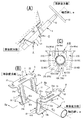
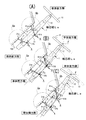
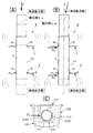
以下、本発明の実施形態を図面に基づいて説明する。本発明は、図1,図2に示すように、主にステアリングコラム1、前方側ブラケットA、後方側ブラケットB等から構成される。ステアリングコラム1は、コラムチューブ11とステアリングシャフト12とステアリングホィール13とからなり、前記コラムチューブ11の内部にステアリングシャフト12が同軸方向に備わったものである。該ステアリングシャフト12にはステアリングホィール13が装着されている。前記コラムチューブ11には、軸方向における軸芯線Laが設定される。該軸芯線Laは、コラムチューブ11の直径中心を通過する仮想線である。以下の説明では、コラムチューブ11については、軸芯線Laと共に説明される。
Hereinafter, embodiments of the present invention will be described with reference to the drawings. As shown in FIGS. 1 and 2, the present invention mainly includes a
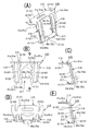
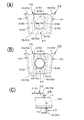
前記前方側ブラケットAは、図3に示すように、取付基部2と、2本の支持アーム部3,3と、コラム接合部4とから構成されている。前記取付基部2は、図3(A),(C)に示すように、板片状に形成されたものであり、前方側ブラケットAを自動車等の車体の室内において、フロント部の下部の被装着部に取付固定する部位であり、基板21の幅方向両側箇所にはボルト固定用の溝孔22,22が形成されている〔図3(A),(D)参照〕。該溝孔22は、長孔形状であり、その長手方向の一端は開口されている。さらに、前記基板21には、スリット21aが形成され、該スリット21aは、前方側ブラケットAの軽量化の役目を果たしている〔図3(A),(D)参照〕。ここで、図1,図3,図9及び図10において、括弧無しの符号は前方側ブラケットAに係るものであり、括弧付きの符号は後方側ブラケットBに係るものである。
As shown in FIG. 3, the front bracket A includes a
前記取付基部2の基板21の前後方向の端部から、2本の支持アーム部3,3が形成されている〔図3(A),(B)参照〕。該支持アーム部3は、前記取付基部2と一体形成されたもので、前記基板21の幅方向両側箇所より下方に向かって、傾斜した状態で形成されている〔図3(C)参照〕。具体的には、前記取付基部2の基板21との延長線と前記支持アーム部3とのなす角度θaは90度未満の鋭角とする。具体的な角度θaの値は、90度乃至50度である。前記支持アーム部3の幅方向中央には断面略円弧形状の補強リブ32が、前記支持アーム部3の長手方向に沿って形成されている。
Two
前記支持アーム部3において、その上部位置は、前記取付基部2の基板21からの付根箇所であり、これを支持アーム部3の付根部31aと称する〔図3(A),(C),(E)参照〕。また、前記支持アーム部3の下部位置は自由端31bと称する〔図3(A),(C),(E)参照〕。すなわち前記支持アーム部3が車体の衝突による衝撃荷重によって、前記付根部31aを回転中心として折れ曲がり、自由端31bは、前記付根部31aを回転中心とする(後述する)軌跡円Qaに沿って移動することになる〔図4(A)参照〕。
In the
前記両支持アーム部3,3の対向する端縁、すなわち両支持アーム部3,3の内側端縁3aには、コラム支持突起33が形成されている〔図3(A),(B)参照〕。該コラム支持突起33は、両支持アーム部3,3の間に前記コラムチューブ11が配置された状態で、前記両コラム支持突起33,33が前記コラムチューブ11の外周側面11aに当接した状態となる〔図1(C)参照〕。また両コラム支持突起33,33は、前記コラムチューブ11の前記外周側面11aに対して適宜の押圧力がかかるようにすることもある。
Column support protrusions 33 are formed on opposite edges of the
前記両支持アーム部3,3の下部位置にはコラム接合部4が形成されている〔図3(A),(B),(E)参照〕。該コラム接合部4は、底板部41の上方にコラム受部42が形成されたものである。前記底板部41は、前記両支持アーム部3,3の下端箇所に、該両支持アーム部3,3と一体形成されたものである。前記底板部41は、前記取付基部2の基板21と略平行且つ同方向に突出するように形成されている。
A column
コラム受部42は前記底板部41から僅か上方位置で且つ前記両支持アーム部3,3との間に形成されたものである。コラム受部42には、垂直状部42bの上端に受面部42aが屈曲形成されたものである。前記垂直状部42bは、前記受面部42aを前記底板部41より僅かの高さとなる位置に形成されたものである。前記受面部42aは、略円弧状の面を有する部位であり、前記コラムチューブ11の直径と略同一の曲率半径Rによって形成されている。前記コラム受部42の受面部42aには、前記コラムチューブ11が配置され、溶接によって、コラム受部42とコラムチューブ11とが固着される〔図1(C),図2(A),図3(E)参照〕。
The
前記後方側ブラケットBは、図3に示すように、前記前方側ブラケットAと同一又は略同一の構造であり、取付基部5と、2本の支持アーム部6,6と、コラム接合部7とから構成されている。前記取付基部5は、前方側ブラケットAの取付基部2と同等の構成であり、基板51の幅方向両側箇所にはボルト固定用の溝孔52,52が形成されている。さらに、前記基板51には、スリット51aが形成されている。前記基板51の前後方向の端部から、2本の支持アーム部6,6が形成され、補強リブ62が形成されている。
As shown in FIG. 3, the rear bracket B has the same or substantially the same structure as the front bracket A, and includes a mounting
前記支持アーム部6の前記取付基部5からの付根部61aは、前記前方側ブラケットAと同様に、支持アーム部6が車体の衝突による衝撃荷重によって、折れ曲がることができる構成となっている。前記両支持アーム部6,6の対向する端縁、すなわち内側端縁6a,6aには、コラム支持突起63が形成されている。そして、前記支持アーム部6において、その上部位置は、前記取付基部5の基板51からの付根箇所であり、これを支持アーム部6の付根部61aと称する。また、前記支持アーム部6の下部位置は自由端61bと称する。すなわち前記支持アーム部6が車体の衝突による衝撃荷重によって、前記付根部61aを回転中心として折れ曲がり、自由端61bは、前記付根部61aを回転中心とする軌跡円Qbに沿って移動することになる〔図4(A)参照〕。
The
コラム接合部7についても、前記前方側ブラケットAのコラム接合部4と同等の構成であり、コラム受部72は前記底板部71から僅か上方位置で且つ前記両支持アーム部6,6との間に形成されたものである。コラム受部72には、垂直状部72bの上端に受面部72aが屈曲形成されたものであり、前記受面部72aを前記底板部71より僅かの高さとなる位置に形成されたものである。前記受面部72aは、略円弧状の面を有する部位であり、前記コラムチューブ11の直径と略同一の曲率半径によって形成されている。
The column
前記前方側ブラケットAのコラム支持突起33は、前記支持アーム部3の高さ方向略中央付近に突出するように形成されたり〔図3(B)参照〕、或いは前記支持アーム部3の高さ方向の略中央箇所から下端箇所まで連続的に形成されることもある〔図10(A)参照〕。特に、前記コラム支持突起33が支持アーム部3の高さ方向略中央箇所から下端箇所まで連続的に形成されたものでは、両支持アーム部3の両コラム支持突起33,33の内端は、平行に形成される。また、コラム支持突起33が前記両支持アーム部3,3に形成されない実施形態も存在する〔図10(B)参照〕。
The
さらにコラム接合部4については、受面部42aが形成されず、前記垂直状部42bの上端縁がそのまま、コラムチューブ11の外周側面11aと溶接にて固着されることもある〔図10(C)参照〕。前記後方側ブラケットBのコラム支持突起63及びコラム接合部7の実施形態についても前記前方側ブラケットのコラム支持突起33及びコラム接合部と同様の実施形態を有するものである。
Further, in the column
前記前方側ブラケットAと、前記後方側ブラケットBとは、同一形状で且つ同一サイズとしたものが最も好ましく、前方側ブラケットAを前後方向に向きを変えることで、後方側ブラケットBとして使用することができる(図2参照)。したがって、前記前方側ブラケットAと同様に、前記後方側ブラケットBにおいて、前記取付基部5の基板51の延長線と前記支持アーム部6とのなす角度θbは90度未満の鋭角であり、具体的な角度θbの値は、90度未満乃至50度である。前記角度α及び角度βの数値は、主にステアリングコラム1の取付角度によって、設定されるものである。前記前方側ブラケットAの支持アーム部3と、前記後方側ブラケットBの支持アーム部6とは、共に付根部31a及び付根部61aを回転中心として折れ曲がることにより、衝突における衝撃を吸収するものである〔図4(A)参照〕。
Most preferably, the front bracket A and the rear bracket B have the same shape and the same size, and the front bracket A is used as the rear bracket B by changing the direction in the front-rear direction. (See FIG. 2). Therefore, similarly to the front bracket A, in the rear bracket B, the angle θb formed between the extension line of the
次に、本発明におけるステアリング装置の車体への装着構造を説明する。ここでは、前方側ブラケットAと後方側ブラケットBとは、同一形状のものが使用されるものとして説明する。コラムチューブ11は、前記前方側ブラケットA及び前記後方側ブラケットBに予め組み付けられ溶接にて固着されている(図2参照)。前記ステアリングシャフト12におけるコラムチューブ11は、前記前方側ブラケットAと前記後方側ブラケットBによって、車体の運転席箇所において、被装着部100に装着される。前方側ブラケットAは、その被装着部100の領域内において、車体の前方側、すなわち前輪側寄りの位置に取り付けられる。前記後方側ブラケットBは、被装着部100の領域内において後方側、すなわちステアリングホィール13側寄りに取り付けられる(図2参照)。
Next, a structure for mounting the steering device to the vehicle body in the present invention will be described. Here, the front bracket A and the rear bracket B will be described as having the same shape. The
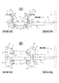
前記前方側ブラケットA及び後方側ブラケットBは、その取付基部2及び取付基部5を介して、ボルト等の固着具によって固着される。コラムチューブ11は、軸方向において前方側が前方側ブラケットAのコラム接合部4のコラム受部42に形成された受面部42aに配置され、溶接にて固着される。また、前記コラムチューブ11の軸方向後方側は、後方側ブラケットBのコラム接合部7のコラム受部72に形成された受面部72aに配置され、溶接にて固着される。前記コラムチューブ11の軸方向に対して前方側ブラケットAと後方側ブラケットBとは、軸方向に沿って左右対称の状態で前記被装着部100に装着されている〔図1(A)参照〕。
The front bracket A and the rear bracket B are fixed by a fixing tool such as a bolt through the mounting
前記前方側ブラケットAと、前記後方側ブラケットBにおける被装着部100に装着状態において、前方側ブラケットAの支持アーム部3は、その下方の自由端31b側が上方の付根部31a側よりも車体後方側すなわちステアリングホィール13寄りの方向に向かうように傾斜する状態となる〔図1(A),図2(A)参照〕。また、後方側ブラケットBの支持アーム部6は、その下方の自由端61b側が上方の付根部61a側よりも車体前方側すなわち前輪側寄りの方向に向かうように傾斜する状態となる〔図1(A),図2(A)参照〕。
When mounted on the mounted
具体的には、前方側ブラケットAの支持アーム部3の下方の自由端31b側と、後方側ブラケットBの支持アーム部6の下方の自由端61b側とが近接し、前記支持アーム部3と前記支持アーム部6とが略V字形状をなすように構成される〔図1(A),図2(A)参照〕。すなわち、対向して配置された前方側ブラケットAと後方側ブラケットBとの外方に前記取付基部2と、前記取付基部5とが位置するように設置されるものである〔図2(A)参照〕。
Specifically, the lower
また、前方側ブラケットAの支持アーム部3及び後方側ブラケットBの支持アーム部6にコラム支持突起33及びコラム支持突起63がそれぞれ形成された実施形態〔図1(C),図3(B)参照〕のものにおいては、前記コラムチューブ11の後方側の外周側面11aが、前記両コラム支持突起33,33によって挟持された状態で支持され、前記コラムチューブ11の前方側の外周側面11aが、前記両コラム支持突起63,63によって挟持された状態で支持されている〔図1(C),図2(B),図9参照〕。このような構成によって、コラムチューブ11の水平方向及び直径方向が確実に安定した状態で固定支持される。
Further, an embodiment in which a
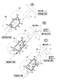
前方側ブラケットAの支持アーム部3と、前記軸芯線Laとのなす角度αと、後方側ブラケットBの支持アーム部6と前記軸芯線Laとのなす角度βとすると、通常状態又は初期状態すなわち衝突前の状態では角度α=角度βである〔図2(A)参照〕。ここで、前方側ブラケットAと軸芯線Laにおける角度αとは、前記支持アーム部3の裏側の面3rと前記軸芯線Laとのなす角度〔図2(B),図3(C),(D)参照〕であり、角度αは、角度90度に到達しない鋭角である。
When the angle α formed between the
そして、初期状態(衝突前の状態)においては、前記角度αと前記角度θaとは同一角度であり、前記角度βと前記角度θbとは、同一角度である。(なお、初期条件によっては、前記角度αと前記角度θaとは異なる角度であり、前記角度βと前記角度θbとも異なる角度となることもある。)また、前方側ブラケットAの取付基部2の基板21と前記軸芯線Laは、平行であり、後方側ブラケットBの取付基部5の基板51と前記軸芯線Laとも平行である。
In the initial state (the state before the collision), the angle α and the angle θa are the same angle, and the angle β and the angle θb are the same angle. (Depending on the initial conditions, the angle α and the angle θa are different from each other, and may be different from the angle β and the angle θb.) Also, the mounting
また、後方側ブラケットBと軸芯線Laにおける角度βとは、前記支持アーム部6の裏側の面6rと前記軸芯線Laとのなす角度〔図2(B),図3(C),(D)参照〕であり、角度βは、角度90度に到達しない鋭角である。これらの角度の数値は、前述したように、ステアリングコラム1の車体への取付角度によって決定される。本明細書では、構造を理解し易くするために、角度α及び角度βは70度を採用している。しかし、角度α及び角度βは、前述した数値に限定されるものではなく、前述した角度θa及び角度θbで設定した90度未満乃至50度の鋭角の範囲であれば、いずれの数値でも構わない。
Further, the angle β between the rear bracket B and the axis line La is an angle formed between the
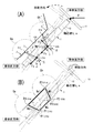
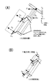
次に、本発明において、衝突による衝撃荷重Fが加わった場合の衝撃吸収に係る構成を説明する。車体の衝突において、その反動で、運転者がステアリングホィール13等にぶつかる衝撃(いわゆる2次衝突)によって、衝撃荷重Fがステアリングホィール13からコラムチューブ11に伝達される。ここで、衝撃荷重Fは、水平方向の荷重とする。衝撃荷重Fは、軸芯線Laに対して平行なX方向分力Fxと、軸芯線Laに対して直角なY方向分力Fyとに分けられる〔図4(A)参照〕。
Next, in the present invention, a configuration related to shock absorption when an impact load F due to a collision is applied will be described. In the collision of the vehicle body, the impact load F is transmitted from the
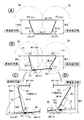
さらに、前方側ブラケットA,後方側ブラケットB及びコラムチューブ11の組付構成において、前記支持アーム部3の付根部31aと、前記支持アーム部6の付根部61aと、前記コラム接合部4、前記コラム接合部7とを仮想線で結ぶことにより、図4(B)に示すように、4本の仮想リンクからなる擬似的な仮想リンク機構にすることができる。この擬似的リンク構造では、初期状態(衝突前の状態)では、前記コラム接合部4とコラムチューブ11との接合点を連結点P1、前記コラム接合部7と前記コラムチューブ11との接合点を連結点P2、前記付根部61aを連結点P3、前記付根部31aを連結点P4と称する。
Furthermore, in the assembly structure of the front bracket A, the rear bracket B, and the
ここで、前記コラム接合部4とコラムチューブ11との接合点は、支持アーム部3の自由端31bと同一位置とし、したがって、連結点P1の位置は、支持アーム部3の自由端31bの位置である。同様に、連結点P2の位置は、支持アーム部6の自由端61bの位置である。さらに連結点P1と連結点P2とを結ぶ仮想線を仮想リンクMaとする。該仮想リンクMaは、コラムチューブ11に対応する。連結点P2と連結点P3とを結ぶ仮想線を仮想リンクMbとする。該仮想リンクMbは後方側ブラケットBの支持アーム部6に対応する。
Here, the joint point between the column
また、連結点P3と連結点P4とを結ぶ仮想線を仮想リンクMcとする。該仮想リンクMcは、前記被装着部100に対応する。連結点P4と連結点P1とを結ぶ仮想線を仮想リンクMdとする。該仮想リンクMdは前方側ブラケットAの支持アーム部3に対応する。図7及び図8では、仮想リンク機構を理解し易くするために、仮想リンクMc、すなわち被装着部100を水平にしたものである。実際には被装着部100は所定の角度を有している。
A virtual line connecting the connection point P3 and the connection point P4 is defined as a virtual link Mc. The virtual link Mc corresponds to the
上記のように仮想リンクMa,仮想リンクMb,仮想リンクMc,仮想リンクMdを設定すると、前方側ブラケットAと後方側ブラケットBとコラムチューブ11は、初期状態(すなわち衝突前の状態)で、前記仮想リンクMa,仮想リンクMb,仮想リンクMc,仮想リンクMdによる擬似的な仮想リンク機構は、左右対称の台形状を構成する〔図4(B),図6(A),図7(A)参照〕。そして、前記コラムチューブ11の軸芯線Laは、前記仮想リンクMaと常時平行であり、仮想リンクMaと軸芯線Laとは、共に平行状態を維持しながら移動する。すなわち、仮想リンクMaの軸方向における動作は、コラムチューブ11の軸芯線Laの動作となる。
When the virtual link Ma, the virtual link Mb, the virtual link Mc, and the virtual link Md are set as described above, the front bracket A, the rear bracket B, and the
2次衝突において、運転者がステアリングホィール13にぶつかるときには、すなわち、衝撃荷重Fがステアリングコラム1のステアリングホィール13に加わるということである〔図4(A)参照〕。そして、後方側ブラケットBの支持アーム部6は、コラムチューブ11の軸芯線Laに沿って、支持アーム部6の自由端61b側が車体前方側に向かって傾斜しているので、前記衝撃荷重FのX方向分力Fxによって、支持アーム部6が付根部61aを回転中心として支持アーム部6の自由端61bが車体前方に向かうように移動する〔図5(B),(C)参照〕。このX方向分力Fxは、前記軌跡円Qbに沿う分力Fxaと分力Fxbとの構成となり、前記分力Fxaによって、連結点P2(支持アーム部6の自由端61b)が車体前方側に移動しつつ、分力Fxbに対する反力Frが支持アーム部6に生じて、前記連結点P2が前記被装着部100に向かって近接するように移動する〔図6,図7(B),(D)及び図8(A),(C)参照〕。
When the driver hits the
このとき、コラムチューブ11の軸芯線Laと支持アーム部6とのなす角度βの数値は、衝突前の初期状態のときよりも小さくなる〔図5(A),(C),図6(A),(C),図7(A),(D),図8(C)参照〕。そして、前記後方側ブラケットBのコラム接合部7の受面部72aとコラムチューブ11との接合箇所は、前記支持アーム部6の付根部61aを回転中心とする軌跡円Qbに沿って、前記自由端61bと共に車体前方側に移動する〔図5(B),(C),図6(B),(C),図7(D),図8(C)参照〕。
At this time, the numerical value of the angle β formed between the axial center line La of the
一方、前方側ブラケットAの支持アーム部3は、コラムチューブ11の軸芯線Laに沿って、支持アーム部3の自由端31b側が車体後方側に向かって傾斜している〔図4(A)参照〕。該支持アーム部3は、前記衝撃荷重FのX方向分力Fxが伝達され、このX方向分力Fxがさらに前記軌跡円Qaに沿う分力Fxa’と分力Fxb’との構成となり、前記分力Fxa’によって、分力Fxb’に対する反力Fr’が支持アーム部3に生じて、連結点P1(支持アーム部3の自由端31b)が車体前方側に移動しつつ、前記被装着部100から離間するように移動する〔図5(B),(C),図6,図7(B),(C)及び図8(A),(B)参照〕。
On the other hand, in the
前記支持アーム部3は、付根部31aを回転中心として支持アーム部3の自由端31bが車体前方に向かうように回転する〔図7(B),(C),図8(A),(B)参照〕。このとき、コラムチューブ11の軸芯線Laと支持アーム部3とのなす角度αの数値は、衝突前の初期状態のときよりも大きくなる〔図5(A),(C),図6(A),(C),図7(A),(C),図8(B)参照〕。そして、前記前方側ブラケットAのコラム接合部4の受面部42aとコラムチューブ11との接合箇所は、前記支持アーム部3の付根部31aを回転中心とする軌跡円Qaに沿って、前記自由端31bと共に車体前方側に移動する〔図5(B),(C),図6,図7(B),(C)及び図8(A),(B)参照〕。
The
このように衝撃荷重Fの発生による後方側ブラケットBと前方側ブラケットAとの動作により、前記コラムチューブ11における後方側ブラケットBとの接合箇所は、車体前方側に移動しつつ、前記被装着部100すなわち取付基部5に近接し、且つ前記コラムチューブ11における前方側ブラケットAとの接合箇所は、車体前方側に移動しつつ、前記被装着部100すなわち取付基部2側から離間する。
Thus, by the operation of the rear side bracket B and the front side bracket A due to the generation of the impact load F, the joint portion of the
上記作動を擬似仮想リンク機構の面から説明すると、まず、仮想リンクMc(車体の被装着部100)を水平方向に設置し、仮想リンクMa,Mb,Mc,Mdによって、左右対称な台形の仮想リンク機構を構成するものとする〔図4(B),図6(B),図7(A)参照〕。仮想リンクMdと仮想リンクMbは同一長さで、V字形状となるように対向している。
The above operation will be described in terms of the pseudo-virtual link mechanism. First, the virtual link Mc (the mounted
すなわち、初期状態(衝突前の状態)においては、前記仮想リンクMa,Mb,Mc,Mdによる台形は、左右対称の逆台形である。このとき、仮想リンクMcと連結点P1との距離Ha0と、仮想リンクMcと連結点P2との距離Hb0とは同一である〔図7(A)参照〕。すなわち、距離Ha0=距離Hb0である。また、初期状態において、前記連結点P1は、軌跡円Qaの直径中心より車体後方側の領域に位置しており、前記連結点P2は、軌跡円Qbの直径中心より車体前方側の領域に位置している。 That is, in the initial state (the state before the collision), the trapezoid formed by the virtual links Ma, Mb, Mc, and Md is a left-right symmetric inverted trapezoid. At this time, the distance Ha0 between the virtual link Mc and the connection point P1 is the same as the distance Hb0 between the virtual link Mc and the connection point P2 (see FIG. 7A). That is, distance Ha0 = distance Hb0. In the initial state, the connection point P1 is located in a region on the rear side of the vehicle body from the diameter center of the locus circle Qa, and the connection point P2 is located in a region on the vehicle body front side from the diameter center of the locus circle Qb. is doing.
このような状態において、2次衝突において、衝撃荷重FのX方向分力Fxが車体後方側(ステアリングホィール13側)から車体前方側にかかるものである。以下、衝撃吸収行程について述べる。図6(B),図7(B),(C),(D)は、衝撃吸収過程が行われている途中の状態である。連結点P2(自由端61b)に衝撃荷重FのX方向分力Fxがかかり、仮想リンクMb(支持アーム部6)は、連結点P3を回転中心として回転し、この回転に伴って連結点P2は軌跡円Qbに沿って、車体前方側へ移動を開始しつつ、連結点P2は、仮想リンクMc(車体の被装着部100)に近接し、前記距離Hb0は減少して距離Hb1となる〔図7(B),(D)参照〕。
In such a state, in the secondary collision, the X-direction component force Fx of the impact load F is applied from the vehicle body rear side (
一方、仮想リンクMa(コラムチューブ11)は仮想リンクMb(支持アーム部6)の回転によって、車体前方側へ移動するものであり、該仮想リンクMaによって仮想リンクMd(支持アーム部3)が連結点P4を中心にして回転し、この回転に伴って連結点P1は軌跡円Qaに沿って、車体前方側へ移動しつつ、連結点P1は、仮想リンクMc(車体の被装着部100)から離間し、前記距離Ha0は増加して距離Ha1となる〔図7(B),(C)参照〕。すなわち、距離Ha1>距離Hb1となり、前記仮想リンクMaは車体後方側すなわちステアリングホィール13側寄りが上昇するように傾斜する。
On the other hand, the virtual link Ma (column tube 11) moves forward of the vehicle body by the rotation of the virtual link Mb (support arm portion 6), and the virtual link Md (support arm portion 3) is connected by the virtual link Ma. The connection point P1 moves from the virtual link Mc (the mounted
図5(C),図6(C),図8(A),(B),(C)は、衝撃吸収が完了した状態である。連結点P2(自由端61b)には、さらに継続して衝撃荷重FのX方向分力Fxがかかり、仮想リンクMb(支持アーム部6)は、連結点P3を回転中心として回転し、この回転に伴って連結点P2は軌跡円Qbに沿って、車体前方側へ移動を開始しつつ、連結点P2は、前記分力Fxa及び分力Fxbによって仮想リンクMc(車体の被装着部100)に近接し、距離Hb1は減少して距離Hb2となる〔図8(A),(C)参照〕。
FIG. 5C, FIG. 6C, FIG. 8A, FIG. 8B, and FIG. The connection point P2 (
一方、仮想リンクMa(コラムチューブ11)は仮想リンクMb(支持アーム部6)の回転によって、車体前方側へ移動するものであり、該仮想リンクMaによって仮想リンクMd(支持アーム部3)が連結点P4を中心にして回転し、この回転に伴って連結点P1は軌跡円Qaに沿って、車体前方側へ移動しつつ、連結点P1は、仮想リンクMc(車体の被装着部100)から離間し、前記距離Ha1は増加して距離Ha2となる〔図8(A),(B)参照〕。すなわち、距離Ha2>距離Hb2となり、前記仮想リンクMaは車体後方側すなわちステアリングホィール13側寄りがより一層上昇し、傾斜して初期状態(衝突前の状態)の仮想リンクMaに対して、衝撃吸収の完了時の仮想リンクMaは角度γである〔図8(A)参照〕。
On the other hand, the virtual link Ma (column tube 11) moves forward of the vehicle body by the rotation of the virtual link Mb (support arm portion 6), and the virtual link Md (support arm portion 3) is connected by the virtual link Ma. The connection point P1 moves from the virtual link Mc (the mounted
なお、前記後方側ブラケットBの支持アーム部6の自由端61b(連結点P1)及び前記前方側ブラケットAの支持アーム部3の自由端31bには、衝撃荷重FのX方向分力Fxと共に、Y方向分力Fyが加わって行われるものである。Y方向分力Fyは、前記連結点P2(支持アーム部6の自由端61b)に対しては上方にかかる分力であり、連結点P2を上方に押し上げる分力となる。さらに、前記連結点P1(支持アーム部3の自由端31b)に対しては下方にかかる分力であり、連結点P1を下方に押し下げる分力となるものである。
The
コラムチューブ11の衝撃吸収における移動状態は、図4(B)に示す矢印の動作となる。仮想リンクMaは、2次衝突によって、コラムチューブ11が車体後方側、すなわちステアリングホィール13側が上方に移動しつつ、傾斜すると共にコラムチューブ11は軸方向において車体前方側に移動するものである。そして、初期状態(衝突前の状態)におけるコラムチューブ11の軸芯線Laに対して、2次衝突によって衝撃吸収した状態のコラムチューブ11の軸芯線Laの傾斜角度は、衝撃完了時には、角度γだけ増加する〔図8(A)参照〕。
The movement state in the shock absorption of the
このように衝撃荷重Fの発生による後方側ブラケットBと前方側ブラケットAとの動作により、前記コラムチューブ11における後方側ブラケットBとの接合箇所は、車体前方側に移動しつつ、前記被装着部100すなわち取付基部5側に近接し、且つ前記コラムチューブ11における前方側ブラケットAとの接合箇所は、車体前方側に移動しつつ、前記被装着部100すなわち取付基部2側から離間し、この動作によって、2次衝突の衝撃を吸収することができる〔図4(B)の矢印参照〕。
Thus, by the operation of the rear side bracket B and the front side bracket A due to the generation of the impact load F, the joint portion of the
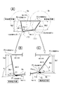
前記前方側ブラケットAの支持アーム部3及び後方側ブラケットBの支持アーム部6にコラム支持突起33及びコラム支持突起63がそれぞれ形成された実施形態のものにおいては、図1(C),図9(A)に示すように、前記コラムチューブ11の後方側(ステアリングホィール13側)の外周側面11aが、前記両コラム支持突起33,33によって挟持された状態で支持され、前記コラムチューブ11の前方側(車体の前方側)の外周側面11aが、前記両コラム支持突起63,63によって挟持された状態で支持されている。このような構成によって、コラムチューブ11は、軸芯線Laが水平面上において傾いたり、倒れたりすることなく、軸方向に沿ってのみ車体前方側に移動することができる。
In the embodiment in which the
特に、水平方向において傾いた状態でステアリングホィール13を介してコラムチューブ11に衝撃荷重Fがかかる(作用する)ときには、そのままでは、図9(B)に示すように、コラムチューブ11は水平面上において、傾いたり、倒れたりすることが有りうる。このような状態に対して、コラムチューブ11の外周側面11aの前方側及び後方側が、前記両コラム支持突起33,33及び前記コラム支持突起63,63によって、それぞれ挟持されているので、コラム支持突起33及びコラム支持突起63にそれぞれ反力Fsが作用し、この反力Fsによって、コラムチューブ11が傾いたり倒れたりすることを防止し、コラムチューブ11を軸方向に沿ってのみ移動させることができる〔図9(B),(C)参照〕。
In particular, when an impact load F is applied (acts) to the
また、前記前方側ブラケットAの支持アーム部3のコラムチューブ11の軸芯線Laに対する傾斜角度αと、前記後方側ブラケットBの支持アーム部6のコラムチューブ11の軸芯線Laに対する傾斜角度βとが、異なるように形成することによって、種々の衝撃吸収のために対応することができる構成にすることができる。
In addition, an inclination angle α of the
A…前方側ブラケット、B…後方側ブラケット、11…コラムチューブ、
100…被装着部、2(5)…取付基部、3(6)…支持アーム部、
4(7)…コラム接合部、42a(72a)…受面部、La…軸芯線。
A ... Front bracket, B ... Rear bracket, 11 ... Column tube,
100 ... Mounted part, 2 (5) ... Mounting base, 3 (6) ... Support arm part,
4 (7) ... column joint part, 42a (72a) ... receiving surface part, La ... shaft core wire.
Claims (6)
Priority Applications (1)
| Application Number | Priority Date | Filing Date | Title |
|---|---|---|---|
| JP2008321301A JP2010143334A (en) | 2008-12-17 | 2008-12-17 | Impact absorbing device of steering device |
Applications Claiming Priority (1)
| Application Number | Priority Date | Filing Date | Title |
|---|---|---|---|
| JP2008321301A JP2010143334A (en) | 2008-12-17 | 2008-12-17 | Impact absorbing device of steering device |
Publications (1)
| Publication Number | Publication Date |
|---|---|
| JP2010143334A true JP2010143334A (en) | 2010-07-01 |
Family
ID=42564218
Family Applications (1)
| Application Number | Title | Priority Date | Filing Date |
|---|---|---|---|
| JP2008321301A Pending JP2010143334A (en) | 2008-12-17 | 2008-12-17 | Impact absorbing device of steering device |
Country Status (1)
| Country | Link |
|---|---|
| JP (1) | JP2010143334A (en) |
Cited By (1)
| Publication number | Priority date | Publication date | Assignee | Title |
|---|---|---|---|---|
| EP4729390A1 (en) * | 2024-10-17 | 2026-04-22 | Jtekt Column Systems France Sas | Part for attaching a steering column to a support of a motor vehicle, associated assembly and associated manufacturing method |
-
2008
- 2008-12-17 JP JP2008321301A patent/JP2010143334A/en active Pending
Cited By (2)
| Publication number | Priority date | Publication date | Assignee | Title |
|---|---|---|---|---|
| EP4729390A1 (en) * | 2024-10-17 | 2026-04-22 | Jtekt Column Systems France Sas | Part for attaching a steering column to a support of a motor vehicle, associated assembly and associated manufacturing method |
| FR3167611A1 (en) * | 2024-10-17 | 2026-04-24 | Jtekt Column Systems France Sas | Steering column mounting component for a motor vehicle, associated assembly and manufacturing process |
Similar Documents
| Publication | Publication Date | Title |
|---|---|---|
| JP2011168190A (en) | Steering position adjusting device | |
| JP2002059853A (en) | Rotational support structure of tilt steering | |
| JP2010254054A (en) | Shock absorbing unit and reclining device | |
| JP5521160B2 (en) | Shock absorbing device for shock absorbing sheet for vehicle | |
| JP5671612B2 (en) | Bumper structure | |
| JP2513633Y2 (en) | Shock absorption type steering column device | |
| JP2008238846A (en) | Vehicle steering device | |
| JP2018083512A (en) | Front subframe structure | |
| JP6252560B2 (en) | Vehicle rear structure | |
| JP2010143334A (en) | Impact absorbing device of steering device | |
| JP2017035999A (en) | Steering device | |
| JP4466686B2 (en) | Steering column device | |
| JP4582374B2 (en) | Tilt steering device | |
| JP2003306095A (en) | Vehicle bumper mounting structure | |
| CN100361852C (en) | Method for manufacturing steering column device for vehicle | |
| JP5508628B2 (en) | Steering device | |
| JP4000459B2 (en) | Shock absorbing steering column device | |
| JP2020097319A (en) | Steering column device | |
| JP2018062213A (en) | Steering device | |
| JP3861525B2 (en) | Auto body front structure | |
| JP4192010B2 (en) | Tilt steering column support device | |
| JP4182684B2 (en) | Method and apparatus for manufacturing vehicle steering column device | |
| JPH0811726A (en) | Impact absorber for steering column | |
| JP7006123B2 (en) | Reverse restraint structure for vehicle pedals | |
| JP2018154312A (en) | Steering device |