JP2010143331A - Meter device for vehicle - Google Patents
Meter device for vehicle Download PDFInfo
- Publication number
- JP2010143331A JP2010143331A JP2008321264A JP2008321264A JP2010143331A JP 2010143331 A JP2010143331 A JP 2010143331A JP 2008321264 A JP2008321264 A JP 2008321264A JP 2008321264 A JP2008321264 A JP 2008321264A JP 2010143331 A JP2010143331 A JP 2010143331A
- Authority
- JP
- Japan
- Prior art keywords
- meter device
- vehicle
- coupler
- support stay
- coupler support
- Prior art date
- Legal status (The legal status is an assumption and is not a legal conclusion. Google has not performed a legal analysis and makes no representation as to the accuracy of the status listed.)
- Granted
Links
Images


Landscapes
- Instrument Panels (AREA)
- Details Of Measuring And Other Instruments (AREA)
- Motorcycle And Bicycle Frame (AREA)
- Time Recorders, Dirve Recorders, Access Control (AREA)
- Lighting Device Outwards From Vehicle And Optical Signal (AREA)
Abstract
【課題】車両用メータ装置において、メータケースから横方向や前方へ突出せず、外形が小さく、周囲の部品やフロントカウル等のレイアウトを制限することなく、保持するカプラが多くなって大型化した場合でも、剛性を確保しやすいカプラホルダを備えた車両用メータ装置を提供しようとするものである。
【解決手段】計器を収納すると共に上部を開口して凹状に形成されたアンダーケースと、計器の上部にレンズを備えると共に下部を開口して凹状に形成されたアッパーケースとから成り、前記アッパーケースが前記アンダーケースの開口側からアンダーケースの外側に重なるようにして取付けられる車両用メータ装置において、メータ用ハーネスと接続先ハーネスとを接続させるカプラ76を支持するカプラ支持ステー81を設け、前記カプラ支持ステー81を、前記メータ装置86の背面側に配置し、前記アッパーケースに取付けた。
【選択図】図33In a meter device for a vehicle, the outer shape is small without protruding from a meter case in the lateral direction or forward, and the number of couplers to be held is increased without restricting the layout of surrounding parts, front cowls, and the like, resulting in an increase in size. Even in this case, an object of the present invention is to provide a vehicular meter device including a coupler holder that can easily ensure rigidity.
The upper case comprises: an undercase that accommodates a meter and is formed in a concave shape by opening the upper portion; and an upper case that is provided with a lens in the upper portion of the meter and that is formed in a concave shape by opening the lower portion. Is mounted so as to overlap the outside of the undercase from the opening side of the undercase, and is provided with a coupler support stay 81 that supports a coupler 76 for connecting the meter harness and the connection destination harness. A support stay 81 was disposed on the back side of the meter device 86 and attached to the upper case.
[Selection] Figure 33
Description
本発明は、自動二輪車、自動三輪車、あるいは鞍乗型自動四輪車などの車両に取付けられるメータ装置に関するものである。 The present invention relates to a meter device attached to a vehicle such as a motorcycle, an automatic tricycle, or a saddle-type automatic four-wheel vehicle.
従来、自動二輪車のメータ装置では、メータ用ハーネスと接続先ハーネスとを接続させるカプラを保持するカプラホルダ部がメータケースに一体に形成されているものが知られている(例えば、特許文献1参照。)。 2. Description of the Related Art Conventionally, a motorcycle meter device is known in which a coupler holder portion for holding a coupler for connecting a meter harness and a connection destination harness is formed integrally with a meter case (see, for example, Patent Document 1). ).
しかし、このカプラホルダ部は、メータケースから横方向に突出する構成であるため、外形が大きくなり、周囲の部品やフロントカウル等のレイアウトが制限されやすい。さらに、保持するカプラが多くなる場合は、カプラホルダ部を大型化する必要があるが、この場合、カプラホルダ部の剛性を確保しにくいという課題があった。 However, since the coupler holder portion is configured to protrude from the meter case in the lateral direction, the outer shape becomes large, and the layout of surrounding parts, the front cowl, and the like is likely to be limited. Furthermore, when the number of couplers to be held increases, it is necessary to increase the size of the coupler holder part. In this case, however, there is a problem that it is difficult to ensure the rigidity of the coupler holder part.
周囲の部品やフロントカウル等のレイアウトに影響を与えることなく、剛性を確保しやすいカプラホルダ部としてのカプラ支持ステーを備えた車両用メータ装置を提供しようとするものである。 An object of the present invention is to provide a vehicular meter device including a coupler support stay as a coupler holder portion that can easily ensure rigidity without affecting the layout of surrounding parts, front cowls, and the like.
本発明は前記課題を解決したものであって、請求項1に記載の発明は、
計器を収納すると共に上部を開口して凹状に形成されたアンダーケースと、
計器の上部にレンズを備えると共に下部を開口して凹状に形成されたアッパーケースとから成り、前記アッパーケースは前記アンダーケースの開口側からアンダーケースの外側に重なるようにして取付けられる車両用メータ装置において、
メータ用ハーネスと接続先ハーネスとを接続させるカプラを支持するカプラ支持ステーを設け、前記カプラ支持ステーを、前記メータ装置の背面側で、且つメータ装置の投影面積内に配置し、前記アッパーケースに取付けたことを特徴とする車両用メータ装置に関するものである。
The present invention solves the above problems, and the invention according to claim 1
An undercase that accommodates the instrument and is formed in a concave shape by opening the upper part,
A vehicular meter device comprising a lens in the upper part of the meter and an upper case formed in a concave shape with an opening in the lower part, the upper case being attached so as to overlap the outside of the under case from the opening side of the under case In
A coupler support stay for supporting a coupler for connecting the meter harness and the connection destination harness is provided, the coupler support stay is disposed on the back side of the meter device and within the projection area of the meter device, and is mounted on the upper case. The present invention relates to a vehicular meter device that is mounted.
請求項2に記載の発明は、請求項1に記載の車両用メータ装置において、
前記アッパーケースの外壁面に、前記カプラ支持ステーを取付けるステー取付け部を設けたことを特徴とするものである。
The invention according to
A stay attaching portion for attaching the coupler support stay is provided on an outer wall surface of the upper case.
請求項3に記載の発明は、請求項2に記載の車両用メータ装置において、
前記アッパーケースの側壁を、前記アンダーケースの側壁より下方まで延ばしたことを特徴とするものである。
The invention according to
The side wall of the upper case is extended below the side wall of the under case.
請求項4に記載の発明は、請求項3に記載の車両用メータ装置において、
前記カプラ支持ステー取付け部は、前記アッパーケースの開口端に設けられることを特徴とするものである。
The invention according to
The coupler support stay attaching portion is provided at an opening end of the upper case.
請求項5に記載の発明は、請求項1乃至請求項4に記載の車両用メータ装置において、
前記メータ装置は、予めトップブリッジ又は車体フレームに取付けられたメータ装置取付け用ステーに、アンダーケースに設けられた取付けボルトを介して取付ける車体取付け部を備え、前記カプラ支持ステーは、前記メータ装置取付け用ステーおよび取付けボルトと干渉しない位置において、アッパーケースに取付けられていることを特徴とするものである。
The invention according to
The meter device includes a vehicle body mounting portion that is mounted on a meter device mounting stay previously mounted on a top bridge or a vehicle body frame via a mounting bolt provided in an undercase, and the coupler support stay is mounted on the meter device mounting It is characterized by being attached to the upper case at a position where it does not interfere with the stay and the mounting bolt.
請求項6に記載の発明は、請求項5に記載の車両用メータ装置において、
カプラ支持ステーは、前記メータ装置の車体取付け部より上方の位置でアッパーケースに取付けられることを特徴とするものである。
The invention according to
The coupler support stay is attached to the upper case at a position above the vehicle body attachment portion of the meter device.
請求項7に記載の発明は、請求項1乃至請求項6に記載の車両用メータ装置において、
カプラ支持ステーは、少なくとも前記アッパーケースの幅方向中央部と、幅方向端部とに固定して取付けられることを特徴とするものである。
The invention according to
The coupler support stay is fixedly attached to at least a width direction center portion and a width direction end portion of the upper case.
請求項8に記載の発明は、請求項1乃至請求項7に記載の車両用メータ装置において、
前記メータ装置は、スピードメータと、スピードメータの側方に配置される他の計器又はインジケータを少なくとも備え、前記カプラ支持ステーは、前記スピードメータと、スピードメータの側方に配置される他の計器またはインジケータの双方の背面にわたって配置されることを特徴とするものである。
The invention according to
The meter device includes at least a speedometer and another instrument or indicator disposed on a side of the speedometer, and the coupler support stay is disposed on the side of the speedometer and the speedometer. Or it is arrange | positioned over the back surface of both of an indicator, It is characterized by the above-mentioned.
請求項9に記載の発明は、請求項1乃至請求項8に記載の車両用メータ装置において、
カプラ支持ステーには、前記メータ装置の背面に沿う部分に開口部が設けられていることを特徴とするものである。
The invention according to
The coupler support stay is characterized in that an opening is provided in a portion along the back surface of the meter device.
請求項10に記載の発明は、請求項1乃至請求項9に記載の車両用メータ装置において、
前記メータ装置を車体に取付けた状態で、カプラ支持ステーは、側面視で前記カプラが車両の前方へ傾くように、カプラ支持面が傾斜して設けてあることを特徴とするものである。
A tenth aspect of the present invention is the vehicle meter device according to any one of the first to ninth aspects,
With the meter device attached to the vehicle body, the coupler support stay is provided with an inclined coupler support surface so that the coupler is inclined forward of the vehicle in a side view.
請求項11に記載の発明は、請求項1乃至請求項10に記載の車両用メータ装置において、
車体に取付けられるヘッドライトと、前記ヘッドライトの上方に配置される前記メータ装置の前方と前記ヘッドライトの周囲とを覆うフロントカウルを備え、前記カプラ支持ステーは、ヘッドライトの上方かつフロントカウルの内側に配置されることを特徴とするものである。
The invention according to
A headlight attached to a vehicle body, and a front cowl that covers the front of the meter device and the periphery of the headlight disposed above the headlight, and the coupler support stay is located above the headlight and on the front cowl. It is arrange | positioned inside, It is characterized by the above-mentioned.
請求項12に記載の発明は、請求項11に記載の車両用メータ装置において、
前記フロントカウルの内側に配置されると共にヘッドライトを支持するインナーカウルを備え、前記インナーカウルはその上部に凹部が形成され、前記凹部に前記カプラ支持ステーが配置されることを特徴とするものである。
The invention according to
The inner cowl is disposed inside the front cowl and supports a headlight, and the inner cowl has a recess formed in an upper portion thereof, and the coupler support stay is disposed in the recess. is there.
請求項13に記載の発明は、請求項11及び請求項12に記載の車両用メータ装置において、
前記ヘッドライトの上方には、車両の前後方向に伸びる遮蔽壁部が設けられ、前記カプラ支持ステーは前記遮蔽壁部の上方に配置されることを特徴とするものである。
The invention according to
A shielding wall portion extending in the front-rear direction of the vehicle is provided above the headlight, and the coupler support stay is disposed above the shielding wall portion.
請求項14に記載の発明は、請求項13に記載の車両用メータ装置において、
前記遮蔽壁部は前記インナーカウルから車両前方へ向けて伸びるよう形成されることを特徴とするものである。
The invention according to
The shielding wall portion is formed to extend from the inner cowl toward the front of the vehicle.
請求項15に記載の発明は、請求項1乃至請求項14に記載の車両用メータ装置において、
ヘッドライト組立体において、フロントカウルをインナーカウルに取付け、
インナーカウルの下部をボトムブリッジに取付け、
インナーカウルの上部をステーを介してトップブリッジに取付ける方法により、
ヘッドライト組立体がメータ装置の下方に設けられることを特徴とするものである。
The invention according to
In the headlight assembly, attach the front cowl to the inner cowl,
Attach the bottom of the inner cowl to the bottom bridge,
By attaching the upper part of the inner cowl to the top bridge via the stay,
A headlight assembly is provided below the meter device.
請求項1の発明において、
カプラ支持ステーを車両用メータ装置の背面側で、且つメータ装置の投影面積内に配置したので、カプラ支持ステーがメータケースから横方向へ突出するのを低減させることができ、外観性を高めることができると共に、周辺部品のレイアウトの自由度を高めることができる。また、カプラ支持ステーをアッパーケースに取付けたので、カプラの保持数を多くしてカプラ支持ステーを大型化した場合であっても、アッパーケースの外殻を使って広い範囲でカプラ支持ステーを支持することができ、カプラ支持ステーの剛性を確保することができる。
In the invention of claim 1,
Since the coupler support stay is arranged on the back side of the vehicle meter device and within the projection area of the meter device, the coupler support stay can be prevented from projecting laterally from the meter case and the appearance can be improved. In addition, the degree of freedom in the layout of peripheral components can be increased. In addition, since the coupler support stay is attached to the upper case, the coupler support stay can be supported in a wide range using the outer shell of the upper case, even when the number of coupler support is increased and the coupler support stay is enlarged. The rigidity of the coupler support stay can be ensured.
請求項2の発明において、
アッパーケースの外壁面にステー取付け部を設けたので、取付け部がアンダーケースと干渉することを防ぐことができ、アッパーケースの外形の小型化を図ることができる
請求項3の発明において、
アッパーケースの側壁をアンダーケースの側壁より下方まで延ばしたので、アッパーケースの剛性を高めることができる。
In the invention of
In the invention according to
Since the side wall of the upper case is extended below the side wall of the under case, the rigidity of the upper case can be increased.
請求項4の発明において、
カプラ支持ステー取付け部をアッパーケースの開口端に設けたので、カプラ支持ステーを容易に取付けることができ、組立性が向上する。
In the invention of
Since the coupler support stay attaching portion is provided at the opening end of the upper case, the coupler support stay can be easily attached, and the assemblability is improved.
請求項5の発明において、
前記カプラ支持ステーは、メータ装置取付け用ステーおよびメータ装置取付けボルトを避けてアッパーケースに取付けられるので、車体側との相互干渉を防ぐことができる。
In the invention of
Since the coupler support stay is attached to the upper case while avoiding the meter device mounting stay and the meter device mounting bolt, mutual interference with the vehicle body side can be prevented.
請求項6の発明において、
カプラ支持ステーをメータ装置の車体取付け部より上方でアッパーケースに取付けられるので、カプラ結線時に、メータ装置の車体取付け部が邪魔になるのを防ぐことができる。したがって、結線作業の効率が向上する。
In the invention of
Since the coupler support stay is attached to the upper case above the vehicle body mounting portion of the meter device, it is possible to prevent the vehicle body mounting portion of the meter device from interfering when the coupler is connected. Therefore, the efficiency of the wiring work is improved.
請求項7の発明において、
カプラ支持ステーは、少なくとも前記アッパーケースの幅方向中央部と、幅方向端部とに固定して取付けられるので、カプラ支持ステーを、アッパーケースのほぼ全体にわたって支持させることができ、支持剛性を強固なものにすることができる。
In the invention of
Since the coupler support stay is fixedly attached to at least the width direction center portion and the width direction end portion of the upper case, the coupler support stay can be supported almost over the entire upper case, and the support rigidity is strong. Can be made.
請求項8の発明において、
カプラ支持ステーを、各種計器類の背面にわたって配置するので、カプラ支持ステーの面積を十分に確保することができ、容易にカプラの保持数を増やすことができる。
In the invention of
Since the coupler support stay is arranged over the back surfaces of various instruments, a sufficient area of the coupler support stay can be secured, and the number of couplers held can be easily increased.
請求項9の発明において、
カプラ支持ステーは、メータ装置の背面に対向する部分に開口部を設けてあるので、メータの放熱性を向上することができる。更に、開口部を形成することにより、メータ用ハーネスの取り廻しを行いやすくすることができる。
In the invention of
Since the coupler support stay has an opening at a portion facing the back surface of the meter device, the heat dissipation of the meter can be improved. Furthermore, by forming the opening, the meter harness can be easily routed.
請求項10の発明において、
カプラ支持ステーのカプラ支持面を、カプラが車体前方へ傾くように傾斜させて設けてあるので、車両前方から、カプラにアクセスし易くなる。したがって、メータ装置を車体に固定した後でも、容易にカプラの結線作業を行うことができる。
In the invention of
Since the coupler support surface of the coupler support stay is inclined so that the coupler is inclined forward of the vehicle body, the coupler can be easily accessed from the front of the vehicle. Therefore, the coupler can be easily connected even after the meter device is fixed to the vehicle body.
請求項11の発明において、
フロントカウルの内側とヘッドライトの上方との間に形成されるデッドスペースにカプラ支持ステーを配置することができ、さらに、外乱の影響を受けにくくすることができる。
In the invention of
The coupler support stay can be disposed in a dead space formed between the inside of the front cowl and the upper portion of the headlight, and can be made less susceptible to disturbance.
請求項12の発明において、
インナーカウルはその上部に凹部が形成され、そこにカプラ支持ステーを配置することができるので、インナーカウルとカプラ支持ステーとの干渉を防ぐことができると共に、インナーカウルによってカプラ支持ステーの周囲を保護することができる。
In the invention of
The inner cowl has a recess in the upper part, and a coupler support stay can be placed there, so that interference between the inner cowl and the coupler support stay can be prevented, and the periphery of the coupler support stay is protected by the inner cowl. can do.
請求項13の発明において、
カプラ支持ステーが遮蔽壁部の上方に配置されるので、遮蔽壁部によってフロントカウルとヘッドライトとの間の隙間からの泥水等の侵入を防ぐことができ、カプラを保護することができる。
In the invention of
Since the coupler support stay is disposed above the shielding wall portion, the shielding wall portion can prevent intrusion of muddy water or the like from the gap between the front cowl and the headlight, thereby protecting the coupler.
請求項14の発明において、
遮蔽壁部をインナーカウルから車両前方へ向けて形成してあるので、インナーカウルに泥水等の浸入を防ぐ機能を持たせることができる。
遮蔽壁部はフロントカウルの背面に形成しても、泥水等の浸入を防ぐ機能を持たせることができるが、この形状では、鋳造固化の際に、素材のポリプロピレンがの収縮し、収縮の影響がフロントカウルの表側に現れて車両の外観性を損ねるので、前記のように、遮蔽壁部をインナーカウルから車両前方へ向けて形成する方が、車両の外観性を高めることができる。
In the invention of
Since the shielding wall portion is formed from the inner cowl toward the front of the vehicle, the inner cowl can be provided with a function of preventing intrusion of muddy water or the like.
Even if the shielding wall part is formed on the back of the front cowl, it can have a function to prevent the intrusion of muddy water, etc., but this shape causes the polypropylene of the material to shrink during casting solidification, and the influence of shrinkage Appears on the front side of the front cowl and impairs the appearance of the vehicle. As described above, it is possible to improve the appearance of the vehicle by forming the shielding wall portion from the inner cowl toward the front of the vehicle.
請求項15の発明において、
車両用メータ装置が取付けられていても、それに制約されることなくヘッドライト組立体を取付けることができる。
In the invention of
Even if the vehicle meter device is attached, the headlight assembly can be attached without being restricted thereto.
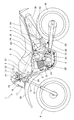
図1は本発明の一実施形態に係る自動二輪車1の側面図である。自動二輪車1の車体フレームはヘッドパイプ2と、同ヘッドパイプ2から斜め後方に延出するメインフレーム3と、メインフレーム3の後端から下方に延出するセンターフレーム4と、ヘッドパイプ2から下方に伸びるダウンフレーム5と、メインフレーム3から後方に延出するシートステー6と、センターフレーム4の下端とシートステー6を結ぶミッドフレーム7と、ダウンフレーム5とメインフレーム3とを結ぶ補強フレーム8と、を備えている。
FIG. 1 is a side view of a motorcycle 1 according to an embodiment of the present invention. The body frame of the motorcycle 1 includes a
前輪9を支持するフロントフォーク10が、ヘッドパイプ2の中に設けられたステアリングステム(図示なし)とトップブリッジ11とボトムブリッジ12とによって操向可能に支持されている。トップブリッジ11には操向ハンドル13が連結され、トップブリッジ11の前側には、メータ装置14が取付けてある。トップブリッジ11とボトムブリッジ12には、インナーカウル15とフロントカウル16によって覆われたヘッドライト17が取付けてある。ボトムブリッジ12には、前輪9を覆うフロントフェンダ18が取付けられている。また、センターフレーム4の後部には、後輪19を支持するリアフォーク20が上下揺動可能に支持され、シートステー6とリアフォーク20との間にはクッションユニット21が設けられている。
A
エンジン22は、補強フレーム8に設けられたエンジン支持ブラケット23によって、吊り下げ支持されると共に、ダウンフレーム5とセンターフレーム4に設けられたブラケット24、25よって前後を支持されている。エンジン22の動力は、後輪駆動用チェーン26を介して後輪19に伝達される。メインフレーム3には、エンジン22の上方に位置するようにして燃料タンク27が設けられ、シートステー6上には運転者用と同乗者用のタンデム型シート28が取付けられている。エンジンの後部には、吸気ポートに連なるスロットルボディ29とエアクリーナ30が設けられ、エンジン22の前部には、排気ポートから延出する排気管31が設けられ、後方へ伸び、後部のマフラー32に接続されている。エアクリーナ30の後方にバッテリ33が設けてある。
The
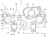
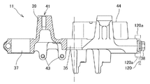
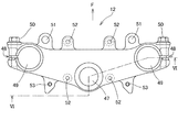
図2〜図4は、トップブリッジ11の図であり、図2はトップブリッジ11の上面図、図3は図2のIII−III断面図、図4は図2のIV−IV断面図である。以下の説明において、各部材の前後左右の表現は、各部材を車両に取付けた状態において、車両の前後左右に対応している。図2、図4において、矢印Fは前方を指している。前記の図において、トップブリッジ11の中央後部には、ステアリングステム挿通孔35が設けられ、左右両端部には、スリット36入りのフロントフォーク保持孔37が設けてある。ステアリングステムの上端部は、ボルト(図示なし)でトップブリッジ11に固定され、フロントフォーク10の上端部は、フロントフォーク保持孔37のスリット36にまたがって装着されたボルト38で締め付け固定される。前記ボルト38によって、後述のヘッドライト組立体取付け用ステー120が共締めされる(図32参照)。図2、図3にはヘッドライト組立体取付け用ステー120の取付け位置が、二点鎖線で示してある。その揺動防止用係合部120aも示してある。トップブリッジ11の後部上面には、操向ハンドル装着部39が設けられ、装着された操向ハンドル13(図1)は、図4に示されるように、上部にハンドル保持部材40をかぶせて、ネジ孔41に螺入されたボルト42で固定される。トップブリッジ11の左側前面には、後述のメータ装置取付け用ステー取付け用ネジ孔43が2箇所設けてある。トップブリッジ11の右側には、前方へ突出するメインスイッチ取付け部44が設けてある。メインスイッチ取付け部44の中央部のメインスイッチ取付け孔45に、メインスイッチとなる後述のメインスイッチ94(図22)が下から取付けられる。
2 to 4 are views of the
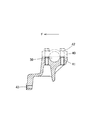
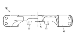
図5〜図6はボトムブリッジ12の図であり、図5はボトムブリッジ12の上面図、図6は図5のVI−VI断面図である。図5において矢印Fは前方をさしている。これらの図において、ボトムブリッジ12の中央後部に、ステアリングステム圧入孔47が設けられ、両端部にスリット48入りのフロントフォーク保持孔49が設けてある。ステアリングステムは、ステアリングステム圧入孔47に圧入固定される。フロントフォーク10はフロントフォーク保持孔49に挿入されて、スリット48にまたがって装着されたボルト50で締め付け固定される。ボトムブリッジ12の前面に、前方へ突出するインナーカウル下部突起挿入孔51が設けてある。これは、後述するヘッドライト17を保持するインナーカウル15の下部突起112(図25、図26)が挿入保持される孔である。ボトムブリッジ12の下面にフロントフェンダ取付けネジ孔52が4個設けてある。ボトムブリッジ12の後面に、スピードセンサハーネス取付けネジ孔53が設けてある。
5 to 6 are views of the
図7は、ヘッドパイプ2内に回動可能に設けられているステアリングステム(図示なし)と、フロントフォーク10、トップブリッジ11、ボトムブリッジ12、との接続状態を示す側面図である。ステアリングステムの上端は、図示していないボルトでトップブリッジ11に固定され、ステアリングステムの下端は、ボトムブリッジ12のステアリングステム圧入孔47(図5)に圧入されている。フロントフォーク10の上端はボルト38で締め付け固定され、フロントフォーク10のボトムブリッジ挿通部は、ボルト50で締め付け固定されている。トップブリッジ11の前面には、メータ装置支持ステー取付けボルト54が用意してある。トップブリッジ11の右側前方にはメインスイッチ取付け部44が突出している。ボトムブリッジ12の前面に、前方へ突出するインナーカウル下部突起挿入孔51が設けてある。
FIG. 7 is a side view showing a connection state between a steering stem (not shown) rotatably provided in the
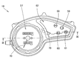
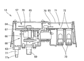
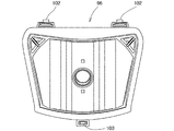
図8〜図10はトップブリッジ11に取付けられるメータ装置14の図であり、図8はメータ装置14の上面図、図9は図8のIX−IX断面図、図10はメータ装置14の下面図である。図8において、メータ装置14の左半部は可動指針式スピードメータ57が占有し、メータ装置14の右半部には、ウインカー表示ランプ58、フューエルインジェクションシステム警告灯59、ハイビーム表示ランプ60、ニュートラル表示ランプ61等の、ランプ指示部62、および燃料残量計79が設けてある。図9において、メータ装置14の殻体はアンダーケース63とアッパーケース64とから成り、アッパーケース64の側面部はアンダーケース63の下部を覆うほど下方へ伸びている。アッパーケース64の上面には、左右にそれぞれ透明なメータ装置用レンズ65が嵌め込まれている。
8 to 10 are views of the
アンダーケース63の左半部には筐体66と表示板67とを一体化した可動指針式ムーブメント68が取付けられ、アンダーケース63と筐体66と表示板67とを回動軸69が貫通し、回動軸69の上端に固定された指針70が、回動軸69と共に回動するようになっている。アンダーケースの右半部において、アンダーケース63とランプ式表示板71との間には、表示板71に設けられた光透過性材料からなる前記の複数の表示マーク72を下から照射する表示マーク照射用ランプ73が設けてある。
A movable
図10はメータ装置14の下面図である。メータ装置の下面には、前記複数のランプ73等の下面から延出する電気配線74がクランプ87によって支持され、これらの電気配線を束ねてメータ装置側ハーネス75が形成され、その先端はカプラ76に接続されている。クランプ87はアンダーケース63に取付けられている。アンダーケース63には複数の通気孔80が設けてある。アッパーケース64の周囲部に、後述のカプラ支持ステー取付け用ネジ孔78が3個設けてある。図9および図10において、スピードメータ57の下方のアンダーケース63に、メータ装置14を車体側へ取付けるための、3本のメータ装置取付けボルト77の頭部が埋設され、それらのネジ部77a(図9)が下方へ伸びている。
FIG. 10 is a bottom view of the
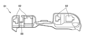
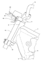
図11〜図13はカプラ支持ステー81の図であり、図11はカプラ支持ステー81の側面図、図12は図11のXII矢視図、図13は図11のXIII矢視図である。図11において、カプラ支持ステー81は、メータ装置14の下面に沿う部分とカプラ76を保持する部分とからなっている。図12はメータ装置14の下面に沿う面、図13はカプラ76を保持する面である。図12のメータ装置14の下面に沿う面には、バッテリカットリレー取付け部127が設けてある。また、開口部83が設けられているので、メータ装置14の放熱性を向上することができると共に、メータ装置側ハーネス75(図10)の取り廻しを行いやすくすることができる。図13に示されるカプラを支持する面には、ハーネスガイド部88と複数のカプラ保持孔82が設けてある。またカプラ支持ステー81の前縁には、メータ装置14のカプラ支持ステー取付け用ネジ孔78に取付けるための、ネジ挿通孔84が3箇所設けてある。
11 to 13 are views of the
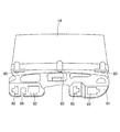
図14〜図15はカプラ支持ステー81をメータ装置14へ取付けた状態の図である。図14はメータ装置14の下面にカプラ支持ステー81が取付けられた状態を下から見た図である。カプラ支持ステー81は、メータ装置14の下面に、図12に示されている面を対向させ、縁部の中央と両端部に設けてあるネジ挿通孔84(図12)を、メータ装置14のアッパーケース64の外周下面に設けられたカプラ支持ステー取付け用ネジ孔78(図10)に対応させ、3本のネジ85によってメータ装置14のアッパーケース64に取付けられる。図15は、メータ装置14の背面側にカプラ支持ステー81を取付けた状態の正面図である。図に見られるようにメータ装置14の幅とカプラ支持ステー81の幅はほぼ等しい。カプラ支持ステーを車両用メータ装置の背面側で、且つメータ装置の投影面積内に配置したので、カプラ支持ステーがメータケースから横方向へ突出するのを低減させることができ、外観性を高めることができる。
14 to 15 are views showing a state in which the coupler support stay 81 is attached to the
図16は、メータ装置14に前記カプラ支持ステー81の取付けがなされた後、メータ装置側カプラ76が、カプラ支持ステー81のカプラ保持孔82(図13〜図15)に装着された状態の側面図である。カプラ保持孔82の下面側から接続先ハーネス95がカプラ76に接続されている。図16のようにメータ装置14とカプラ支持ステー81とハーネス75とカプラ76とが一体となったものをメータ装置組立体86と呼ぶ。
FIG. 16 is a side view showing a state in which the meter
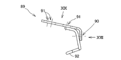
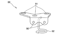
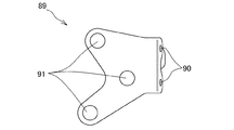
図17〜図19は、メータ装置組立体86を車体へ取付けるために用いるメータ装置取付け用ステー89の図である。図17はメータ装置取付け用ステー89の側面図、図18は図17のXVIII矢視図、図19は図17のXIX矢視図である。メータ装置取付け用ステー89は、平板を折り曲げて作られたものであり、車体側への取付け孔90が2個と、メータ装置取付け孔91が3個設けてある。更に鋼線で作られたハーネス保持部92が溶接されている。
17 to 19 are views of a meter
図20は前記メータ装置取付け用ステー89を、車体側のトップブリッジ11に取付けた状態の側面図である。メータ装置取付け用ステー89は、図2に示されるトップブリッジ11の、メータ装置取付け用ステー取付け用ネジ孔43にメータ装置支持ステー取付けボルト54で取付けられる。
FIG. 20 is a side view of the meter
図21は前記メータ装置取付け用ステー89にメータ装置組立体86が取付けられた状態の側面図である。メータ装置組立体86は、メータ装置14のアンダーケース63に埋設されていた3本のメータ装置取付けボルト77(図16)とナット93によって、メータ装置取付け用ステー89のメータ装置取付け孔91(図19)に取付けられる。
FIG. 21 is a side view showing a state in which the
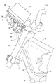
図22は取付けが完了したメータ装置組立体86を下から見た斜視図である。メータ装置組立体86が取付けられた後に、メータ装置側ハーネス75に連なるメータ装置側カプラ76と、接続先ハーネス95に連なる接続先カプラが接続される。またメインスイッチ94から伸びるハーネス75bに連なるカプラ76bと、接続先ハーネス95に連なる接続先カプラが接続される。なお、接続先ハーネス95はバッテリ33(図1)等へ接続される。この時、トップブリッジ11のメインスイッチ取付け部44(図2)に下からメインスイッチ94が取付けられ、上部がキーシャッター(図示なし)で覆われる。
FIG. 22 is a perspective view of the
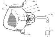
図23〜図24はヘッドライト17の図である。図23は、ヘッドライト17の縦断面図である。ヘッドライト17の殻体は、リフレクタ96とレンズ97とからなっている。リフレクタ96は凹面反射鏡であり、バルブホルダ98に装着されたバルブ99が後部中央に取付けられる。バルブホルダ98の後端から電気コード100が延出し、端部にヘッドライト用カプラ101が接続されている。図24はリフレクタ96の正面図である。リフレクタ96の上部には後述のインナーカウル15への係合突起102が2箇所設けてある。リフレクタ96の下部には、インナーカウル15に装着した後に使用されるビーム照射角度調節部103が1箇所設けてある。
23 to 24 are views of the
図25〜図26はインナーカウル15の図であり、図25はインナーカウル15の側面図、図26はインナーカウル15の正面図である。インナーカウル15は前記ヘッドライト17を内部に保持すると共に、後述のフロントカウル16を外部に保持する部材であり、中央部は前後に貫通する中空部104となっている。図26において、中空部104は、上面壁105、下面壁106、および左右の側壁107に囲まれている。図25において、インナーカウル15の上面壁105は前方へ伸びて、メータ装置への泥水等の侵入を防ぐための遮蔽壁108となっている。上面壁105にはヘッドライト17の係合突起102(図23〜図24)が係合するヘッドライト係合孔109が2箇所設けてある。インナーカウルの下面壁106には、ヘッドライトのビーム照射角度調節部103(図23)が装着されるビーム照射角度調節用長孔110が1箇所設けてある。
25 to 26 are views of the
インナーカウル15の後部左右にはそれぞれヘッドライト組立体取付け用ステー120(図29)へ取付けるための取付け孔111が設けてある。インナーカウル15の下部には、ボトムブリッジ12のインナカウル下部突起挿入孔51(図5)への挿入用の下部突起112が2箇所設けてある。インナーカウル15の上部および下部にはフロントカウル取付け用ネジ挿通孔113がそれぞれ2個ずつ設けてある。図26において、インナーカウル15の上部は、側壁107の上部と上面壁105の上面とによって、凹部119が形成されている。ヘッドライト組立体117を車体側に取付けた時、前記凹部119にメータ装置組立体86のカプラ支持ステー81を配置することができるので、相互の干渉を防ぐことができる。更にカプラ支持ステーの周囲部を保護することができる。
Mounting
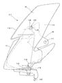
図27はインナーカウル15にヘッドライト17を装着した状態の側面図である。装着に際しては、インナーカウル15の上面壁に設けられたヘッドライト係合孔109に、ヘッドライト17のリフレクタ96の上部に設けられた係合突起102を挿入係合させ、インナーカウル15の下面壁のビーム照射角度調節用長孔110にリフレクタ96下部のビーム照射角度調節部103をネジ止めする。このネジ止めは仮のものであって、最終的なビーム照射角度調節は、ヘッドライト17が車体に取付けられた後に行われる。
FIG. 27 is a side view of the
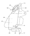
図28はヘッドライト組立体117の完成状態の側面図である。図27に示されるヘッドライト17装着済みのインナーカウル15に、フロントカウル16を上から被せて取付けることによってヘッドライト組立体117が完成する。フロントカウル16は、メータ装置組立体86(図16)の前面を覆う位置に設けられる風雨除けの上部傾斜壁114と、メータ装置組立体86とヘッドライト17装着済みのインナーカウル15の左右を覆う側壁115とからなっている。左右の側壁115の上部と下部にインナーカウルへの取付け用ネジ孔116が形成してある。フロントカウル16は、インナーカウル15の取付けネジ挿通孔113(図26)に挿通したネジ118を、フロントカウル16のネジ孔116に螺入して一体化される。ネジ118は前方斜め下方へ向けて螺入される。
FIG. 28 is a side view of the
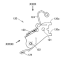
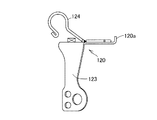
図29〜図31は、ヘッドライト組立体取付け用ステー120の図である。ヘッドライト組立体取付け用ステー120は、左右に対称に取付けられるものであり、図示のものは左側のヘッドライト組立体取付け用ステー120を示している。図29はヘッドライト組立体取付け用ステー120の側面図、図30は図29のXXX矢視図、図31は図29のXXXI矢視図である。ヘッドライト組立体取付け用ステー120の後端部に、トップブリッジ11への取付け用孔121が設けてある。ヘッドライト組立体取付け用ステー120の後端に、ヘッドライト組立体取付け用ステー120の揺動防止のためにトップブリッジ11へ係合する揺動防止用係合部120aが設けてある。ヘッドライト組立体取付け用ステー120の前端部には、ヘッドライト組立体取付け用ネジ孔122が設けてある。このヘッドライト組立体取付け用ステー120には、横方向へ伸びるウインカー取付け部123が一体化されている。更に、鋼線を曲げて作られた複数のハーネス保持部124が溶接されている。
29 to 31 are views of the
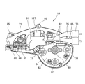
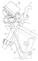
図32は前記ヘッドライト組立体取付け用ステー120をトップブリッジ11に取付けた状態の側面図である。この時にはメータ装置組立体86は、既にトップブリッジ11へ取付けられている。ヘッドライト組立体取付け用ステー120は、トップブリッジ11の左右端部のスリット入りフロントフォーク保持孔37(図2)に、フロントフォーク10を締めつけるために取付けられたボルト38を、図29に示されるトップブリッジへの取付け用孔121に挿通して共締め(図2参照)して、トップブリッジ11に取付けられる。この時揺動防止用係合部120aはトップブリッジの端部の上下に係合し、ヘッドライト組立体取付け用ステー120の揺動が防止される。
FIG. 32 is a side view of the headlight
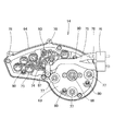
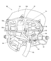
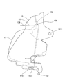
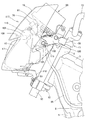
図33は、図28に示したヘッドライト組立体117を、車体側へ取付けた状態を示す側面図である。ヘッドライト組立体117の取付けにあたっては、まずインナーカウル15の下部突起112(図25〜図26)を、ボトムブリッジ12のインナーカウル下部突起挿入孔51(図5)へ挿入した後、インナーカウル15上部の取付け孔111(図25、図28)にボルト125を挿通し、図29のヘッドライト組立体取付け用ステー120のヘッドライト取付け用ネジ孔122(図29)に螺入して固定する。これによってヘッドライト組立体117の車両への取付けが完了する。インナーカウル15の上面壁105(図25、図26)は、メータ装置組立体86のカプラ支持ステー81やカプラ76より下方に位置し、インナーカウル15の側壁107はカプラ支持ステー81の側方に位置する。即ちインナーカウル15の上部の凹部119(図26)にメータ装置組立体86のカプラ支持ステー81やカプラ76を配置することができるので、ヘッドライト組立体117とメータ装置組立体86との相互干渉を防ぐことができる。更にカプラ支持ステーの周囲部を保護することができる。
FIG. 33 is a side view showing a state in which the
以上詳述したように、本実施形態では次の効果がもたらされる。
(1)カプラ支持ステーを車両用メータ装置の背面側で、且つメータ装置の投影面積内に配置したので、カプラ支持ステーがメータケースから横方向へ突出することを防ぐことができ、外観性を高めることができると共に、周辺部品のレイアウトの自由度を高めることができる。また、カプラ支持ステーをアッパーケースに取付けたので、カプラの保持数を多くしてカプラ支持ステーを大型化した場合であっても、アッパーケースの外殻を使って広い範囲でカプラ支持ステーを支持することができ、カプラ支持ステーの剛性を確保することができる。
(2)アッパーケースの外壁面にステー取付け部を設けたので、取付け部がアンダーケースと干渉することを防ぐことができ、アッパーケースの外形の小型化を図ることができる
(3)アッパーケースの側壁をアンダーケースの側壁より下方まで延ばしたので、アッパーケースの剛性を高めることができる。
(4)カプラ支持ステー取付け部をアッパーケースの開口端に設けたので、カプラ支持ステーを容易に取付けることができ、組立性が向上する。
(5)前記カプラ支持ステーは、メータ装置取付け用ステーおよびメータ装置取付けボルトを避けてアッパーケースに取付けられているので、車体側との相互干渉を防ぐことができる。
(6)カプラ支持ステーをメータ装置の車体取付け部より上方でアッパーケースに取付けられるので、カプラ結線時に、メータ装置の車体取付け部が邪魔になるのを防ぐことができる。したがって、結線作業の効率が向上する。
(7)カプラ支持ステーは、少なくとも、アッパーケースの幅方向中央部と幅方向両端部とに固定されるので、カプラ支持ステーは、アッパーケースのほぼ全体にわたって支持され、支持剛性を強固なものにすることができる。
(8)カプラ支持ステーを、各種計器類の背面にわたって配置するので、カプラ支持ステーの面積を十分に確保することができ、容易にカプラの保持数を増やすことができる。
(9)カプラ支持ステーは、メータ装置の背面に対向する部分に開口部を設けてあるので、メータの放熱性を向上することができる。更に、開口部を形成することにより、メータ用ハーネスの取り廻しを行いやすくすることができる。
(10)カプラ支持ステーのカプラ支持面を、カプラが車体前方へ傾くように傾斜させて設けてあるので、車両前方から、カプラにアクセスし易くなる。したがって、メータ装置を車体に固定した後でも、容易にカプラの結線作業を行うことができる。
(11)フロントカウルの内側とヘッドライトの上方との間に形成されるデッドスペースにカプラ支持ステーを配置することができるので、外乱の影響を受けにくい。
(12)インナーカウルの上部には凹部が形成され、そこにカプラ支持ステーを配置するので、ヘッドライト組立体のインナーカウルとカプラ支持ステーとの干渉を防ぐことができると共に、インナーカウルによってカプラ支持ステーの周囲を保護することがができる。
(13)カプラ支持ステーが遮蔽壁部の上方に配置されるので、遮蔽壁部によってフロントカウルとヘッドライトとの間の隙間からの泥水等の侵入を防ぐことができ、カプラを保護することができる。
(14)遮蔽壁部をインナーカウルから車両前方へ向けて形成してあるので、インナーカウルに泥水等の浸入を防ぐ機能を持たせることができる。遮蔽壁部を、フロントカウル側ではなく、インナーカウル側に設けて車両前方へ向けて形成してあるので、車両の外観性を高めることができる。
(15)車両用メータ装置が取付けられていても、それに制約されることなくヘッドライト組立体を取付けることができる。
As described in detail above, the present embodiment provides the following effects.
(1) Since the coupler support stay is disposed on the back side of the vehicle meter device and within the projected area of the meter device, the coupler support stay can be prevented from projecting laterally from the meter case, and the appearance can be improved. It is possible to increase the degree of freedom of the layout of peripheral parts. In addition, since the coupler support stay is attached to the upper case, the coupler support stay can be supported in a wide range using the outer shell of the upper case, even when the number of coupler support is increased and the coupler support stay is enlarged. The rigidity of the coupler support stay can be ensured.
(2) Since the stay mounting portion is provided on the outer wall surface of the upper case, the mounting portion can be prevented from interfering with the under case, and the outer case can be reduced in size (3) Since the side wall is extended below the side wall of the undercase, the rigidity of the upper case can be increased.
(4) Since the coupler support stay attaching portion is provided at the opening end of the upper case, the coupler support stay can be easily attached, and the assemblability is improved.
(5) Since the coupler support stay is attached to the upper case while avoiding the meter device mounting stay and the meter device mounting bolt, mutual interference with the vehicle body side can be prevented.
(6) Since the coupler support stay can be attached to the upper case above the vehicle body mounting portion of the meter device, it is possible to prevent the vehicle body mounting portion of the meter device from interfering when the coupler is connected. Therefore, the efficiency of the wiring work is improved.
(7) Since the coupler support stay is fixed at least to the widthwise central portion and both widthwise end portions of the upper case, the coupler support stay is supported over almost the entire upper case, thereby strengthening the support rigidity. can do.
(8) Since the coupler support stay is arranged over the back surfaces of various instruments, the area of the coupler support stay can be sufficiently secured, and the number of couplers held can be easily increased.
(9) Since the coupler support stay is provided with the opening in the portion facing the back surface of the meter device, the heat dissipation of the meter can be improved. Furthermore, by forming the opening, the meter harness can be easily routed.
(10) Since the coupler support surface of the coupler support stay is inclined so that the coupler is inclined forward of the vehicle body, the coupler can be easily accessed from the front of the vehicle. Therefore, the coupler can be easily connected even after the meter device is fixed to the vehicle body.
(11) Since the coupler support stay can be disposed in a dead space formed between the inside of the front cowl and the upper portion of the headlight, it is less susceptible to disturbance.
(12) Since a concave portion is formed on the upper part of the inner cowl and a coupler support stay is arranged there, interference between the inner cowl of the headlight assembly and the coupler support stay can be prevented, and the coupler support is provided by the inner cowl. The surroundings of the stay can be protected.
(13) Since the coupler support stay is disposed above the shielding wall portion, the shielding wall portion can prevent intrusion of muddy water or the like from the gap between the front cowl and the headlight, thereby protecting the coupler. it can.
(14) Since the shielding wall portion is formed from the inner cowl toward the front of the vehicle, the inner cowl can be provided with a function of preventing entry of muddy water or the like. Since the shielding wall portion is provided not on the front cowl side but on the inner cowl side and formed toward the front of the vehicle, the appearance of the vehicle can be enhanced.
(15) Even if the vehicle meter device is attached, the headlight assembly can be attached without being restricted thereto.
11…トップブリッジ、12…ボトムブリッジ、14…メータ装置、15…インナーカウル、16…フロントカウル、17…ヘッドライト、43…メータ装置取付け用ステー取付け用ネジ孔、44…メインスイッチ取付け部、51…インナーカウル下部突起挿入孔、54…メータ装置支持ステー取付けボルト、63…アンダーケース、64…アッパーケース、68…可動指針式ムーブメント、71…ランプ式表示板、74…電気配線、75…メータ装置側ハーネス、76…メータ装置側カプラ、77…メータ装置取付けボルト、78…カプラ支持ステー取付け用ネジ孔、81…カプラ支持ステー、82…カプラ保持孔、83…開口部、84…ネジ挿通孔、86…メータ装置組立体、89…メータ装置取付け用ステー、105…上面壁、106…下面壁、107…側壁、108…遮蔽壁、117…ヘッドライト組立体、119…凹部(インナーカウルの上部)、120…ヘッドライト組立体取付け用ステー 11 ... Top bridge, 12 ... Bottom bridge, 14 ... Meter device, 15 ... Inner cowl, 16 ... Front cowl, 17 ... Headlight, 43 ... Screw hole for mounting stay for meter device, 44 ... Main switch mounting part, 51 ... Inner cowl lower protrusion insertion hole, 54 ... Meter device support stay mounting bolt, 63 ... Under case, 64 ... Upper case, 68 ... Moveable pointer type movement, 71 ... Lamp type display board, 74 ... Electric wiring, 75 ... Meter device Side harness, 76 ... meter device side coupler, 77 ... meter device mounting bolt, 78 ... couple support stay mounting screw hole, 81 ... coupler support stay, 82 ... coupler holding hole, 83 ... opening, 84 ... screw insertion hole, 86 ... Meter device assembly, 89 ... Meter device mounting stay, 105 ... Upper wall, 106 ... Lower wall, 107 ... Side wall, 108 ... Shielding wall, 117 ... Headlight assembly, 119 ... Recess (inner Ur top), 120: headlight assembly mounting stay
Claims (15)
計器の上部にレンズを備えると共に下部を開口して凹状に形成されたアッパーケースとから成り、
前記アッパーケースは前記アンダーケースの開口側からアンダーケースの外側に重なるようにして取付けられる車両用メータ装置において、
メータ用ハーネスと接続先ハーネスとを接続させるカプラを支持するカプラ支持ステーを設け、
前記カプラ支持ステーを、前記メータ装置の背面側で、且つメータ装置の投影面積内に配置し、前記アッパーケースに取付けたことを特徴とする車両用メータ装置。 An undercase that accommodates the instrument and is formed in a concave shape by opening the upper part,
It consists of an upper case with a lens at the top of the instrument and a concave shape with an opening at the bottom.
In the vehicle meter device, wherein the upper case is attached so as to overlap the outside of the under case from the opening side of the under case,
A coupler support stay is provided to support the coupler that connects the meter harness and the connection harness.
The vehicular meter device, wherein the coupler support stay is disposed on a back surface side of the meter device and within a projection area of the meter device, and is attached to the upper case.
前記カプラ支持ステーは、前記メータ装置取付けステーおよび取付けボルトと干渉しない位置において、アッパーケースに取付けられていることを特徴とする請求項1乃至請求項4に記載の車両用メータ装置。 The meter device includes a vehicle body attachment portion that is attached to a meter device attachment stay that is previously attached to a top bridge or a vehicle body frame via an attachment bolt provided in an undercase,
5. The vehicle meter device according to claim 1, wherein the coupler support stay is attached to the upper case at a position where the coupler support stay does not interfere with the meter device attachment stay and the attachment bolt.
前記ヘッドライトの上方に配置される前記メータ装置の前方と前記ヘッドライトの周囲とを覆うフロントカウルを備え、
前記カプラ支持ステーは、ヘッドライトの上方かつフロントカウルの内側に配置されることを特徴とする請求項1乃至請求項10に記載の車両用メータ装置。 A headlight attached to the vehicle body,
A front cowl that covers the front of the meter device disposed above the headlight and the periphery of the headlight;
11. The vehicle meter device according to claim 1, wherein the coupler support stay is disposed above the headlight and inside the front cowl.
前記インナーカウルはその上部に凹部が形成され、
前記凹部に前記カプラ支持ステーが配置されることを特徴とする請求項11に記載の車両用メータ装置。 The inner cowl is disposed inside the front cowl and supports the headlight,
The inner cowl is formed with a recess at the top,
The vehicle meter device according to claim 11, wherein the coupler support stay is disposed in the recess.
前記カプラ支持ステーは前記遮蔽壁部の上方に配置されることを特徴とする請求項11及び請求項12に記載の車両用メータ装置。 Above the headlight, a shielding wall portion extending in the front-rear direction of the vehicle is provided,
The vehicular meter device according to claim 11, wherein the coupler support stay is disposed above the shielding wall portion.
インナーカウルの下部をボトムブリッジに取付け、
インナーカウルの上部をステーを介してトップブリッジに取付ける方法により、
ヘッドライト組立体がメータ装置の下方に設けられることを特徴とする請求項1乃至請求項14に記載の車両用メータ装置。 In the headlight assembly, attach the front cowl to the inner cowl,
Attach the bottom of the inner cowl to the bottom bridge,
By attaching the upper part of the inner cowl to the top bridge via the stay,
15. The vehicle meter device according to claim 1, wherein the headlight assembly is provided below the meter device.
Priority Applications (5)
| Application Number | Priority Date | Filing Date | Title |
|---|---|---|---|
| JP2008321264A JP4871349B2 (en) | 2008-12-17 | 2008-12-17 | Vehicle meter device |
| MX2009012865A MX2009012865A (en) | 2008-12-17 | 2009-11-27 | Counting device for vehicles. |
| PE2009001304A PE20100612A1 (en) | 2008-12-17 | 2009-12-11 | MEASURING DEVICE FOR USE IN A VEHICLE |
| BRPI0905049-3A BRPI0905049B1 (en) | 2008-12-17 | 2009-12-11 | VEHICLE USE MEASURING DEVICE |
| ARP090104873 AR075315A1 (en) | 2008-12-17 | 2009-12-15 | MEASUREMENT DEVICE FOR USE IN VEHICLES |
Applications Claiming Priority (1)
| Application Number | Priority Date | Filing Date | Title |
|---|---|---|---|
| JP2008321264A JP4871349B2 (en) | 2008-12-17 | 2008-12-17 | Vehicle meter device |
Publications (2)
| Publication Number | Publication Date |
|---|---|
| JP2010143331A true JP2010143331A (en) | 2010-07-01 |
| JP4871349B2 JP4871349B2 (en) | 2012-02-08 |
Family
ID=42564215
Family Applications (1)
| Application Number | Title | Priority Date | Filing Date |
|---|---|---|---|
| JP2008321264A Expired - Fee Related JP4871349B2 (en) | 2008-12-17 | 2008-12-17 | Vehicle meter device |
Country Status (5)
| Country | Link |
|---|---|
| JP (1) | JP4871349B2 (en) |
| AR (1) | AR075315A1 (en) |
| BR (1) | BRPI0905049B1 (en) |
| MX (1) | MX2009012865A (en) |
| PE (1) | PE20100612A1 (en) |
Cited By (5)
| Publication number | Priority date | Publication date | Assignee | Title |
|---|---|---|---|---|
| CN101920739A (en) * | 2010-08-31 | 2010-12-22 | 力帆实业(集团)股份有限公司 | motorcycle front shroud |
| JP2016068699A (en) * | 2014-09-29 | 2016-05-09 | 本田技研工業株式会社 | Saddle-riding type vehicle |
| WO2017130616A1 (en) * | 2016-01-28 | 2017-08-03 | 本田技研工業株式会社 | Coupler holding structure for saddled vehicle |
| DE112018004932B4 (en) | 2017-09-07 | 2024-06-13 | Honda Motor Co., Ltd. | STRUCTURE FOR A FRONT PART OF A SEMI-TRAILER |
| WO2024135830A1 (en) * | 2022-12-22 | 2024-06-27 | 本田技研工業株式会社 | Meter structure for saddle-type vehicle |
Citations (5)
| Publication number | Priority date | Publication date | Assignee | Title |
|---|---|---|---|---|
| JPS5750492A (en) * | 1980-09-10 | 1982-03-24 | Casio Computer Co Ltd | Printed circuit board and method of producing same |
| JPS58177159A (en) * | 1982-04-12 | 1983-10-17 | Koken Kk | Electrostatic filter for filtering air |
| JPS62127879A (en) * | 1985-11-29 | 1987-06-10 | Ricoh Co Ltd | Transfer device |
| JPH08192665A (en) * | 1995-01-17 | 1996-07-30 | Nippondenso Co Ltd | Waterproof construction of instrument for vehicle |
| JP2007125902A (en) * | 2005-10-31 | 2007-05-24 | Honda Motor Co Ltd | Motorcycle meter device |
-
2008
- 2008-12-17 JP JP2008321264A patent/JP4871349B2/en not_active Expired - Fee Related
-
2009
- 2009-11-27 MX MX2009012865A patent/MX2009012865A/en active IP Right Grant
- 2009-12-11 PE PE2009001304A patent/PE20100612A1/en active IP Right Grant
- 2009-12-11 BR BRPI0905049-3A patent/BRPI0905049B1/en active IP Right Grant
- 2009-12-15 AR ARP090104873 patent/AR075315A1/en not_active Application Discontinuation
Patent Citations (5)
| Publication number | Priority date | Publication date | Assignee | Title |
|---|---|---|---|---|
| JPS5750492A (en) * | 1980-09-10 | 1982-03-24 | Casio Computer Co Ltd | Printed circuit board and method of producing same |
| JPS58177159A (en) * | 1982-04-12 | 1983-10-17 | Koken Kk | Electrostatic filter for filtering air |
| JPS62127879A (en) * | 1985-11-29 | 1987-06-10 | Ricoh Co Ltd | Transfer device |
| JPH08192665A (en) * | 1995-01-17 | 1996-07-30 | Nippondenso Co Ltd | Waterproof construction of instrument for vehicle |
| JP2007125902A (en) * | 2005-10-31 | 2007-05-24 | Honda Motor Co Ltd | Motorcycle meter device |
Cited By (9)
| Publication number | Priority date | Publication date | Assignee | Title |
|---|---|---|---|---|
| CN101920739A (en) * | 2010-08-31 | 2010-12-22 | 力帆实业(集团)股份有限公司 | motorcycle front shroud |
| JP2016068699A (en) * | 2014-09-29 | 2016-05-09 | 本田技研工業株式会社 | Saddle-riding type vehicle |
| WO2017130616A1 (en) * | 2016-01-28 | 2017-08-03 | 本田技研工業株式会社 | Coupler holding structure for saddled vehicle |
| CN108463403A (en) * | 2016-01-28 | 2018-08-28 | 本田技研工业株式会社 | Straddle type vehicle connector holding structure |
| JPWO2017130616A1 (en) * | 2016-01-28 | 2018-08-30 | 本田技研工業株式会社 | Coupler holding structure for saddle riding type vehicles |
| DE112018004932B4 (en) | 2017-09-07 | 2024-06-13 | Honda Motor Co., Ltd. | STRUCTURE FOR A FRONT PART OF A SEMI-TRAILER |
| WO2024135830A1 (en) * | 2022-12-22 | 2024-06-27 | 本田技研工業株式会社 | Meter structure for saddle-type vehicle |
| JPWO2024135830A1 (en) * | 2022-12-22 | 2024-06-27 | ||
| JP7814555B2 (en) | 2022-12-22 | 2026-02-16 | 本田技研工業株式会社 | Meter structure for saddle-type vehicles |
Also Published As
| Publication number | Publication date |
|---|---|
| BRPI0905049B1 (en) | 2020-06-16 |
| AR075315A1 (en) | 2011-03-23 |
| PE20100612A1 (en) | 2010-09-09 |
| BRPI0905049A2 (en) | 2011-02-08 |
| JP4871349B2 (en) | 2012-02-08 |
| MX2009012865A (en) | 2010-06-22 |
Similar Documents
| Publication | Publication Date | Title |
|---|---|---|
| JP4104198B2 (en) | Motorcycle headlight and speedometer mounting device | |
| US7681681B2 (en) | Meter device of motorcycle | |
| CN102811900B (en) | Display device for vehicle | |
| JP5328544B2 (en) | Meter cover structure for saddle-ride type vehicles | |
| CN112188979A (en) | straddle vehicle | |
| CN204341290U (en) | The protecgulum cover structure of Straddle-type vehicle | |
| JP4871349B2 (en) | Vehicle meter device | |
| JP5793932B2 (en) | Saddle riding vehicle | |
| US20060056191A1 (en) | Vehicle | |
| TWI427014B (en) | Turn signal device for saddle-ride type vehicle | |
| JP4525256B2 (en) | Rear view mirror support structure for motorcycles | |
| EP3536531B1 (en) | Straddled vehicle | |
| JP2019119441A (en) | Front cowl structure of saddle-riding type vehicle | |
| JP5345484B2 (en) | Motorcycle | |
| JP5921508B2 (en) | Motorcycle meter equipment | |
| JP6119161B2 (en) | Motorcycle | |
| JP2013035305A (en) | Motorcycle | |
| JP5129060B2 (en) | Vehicle cowl stay structure | |
| JP5775914B2 (en) | Cable routing structure for electrical components in saddle-ride type vehicles | |
| JP2015013536A (en) | Motorcycle meter device | |
| CN204210638U (en) | The rear portion assembled unit of motor bike | |
| JP4458426B2 (en) | Winker mounting structure | |
| JPH0995273A (en) | Cowling stay for motorcycles | |
| JP2021030797A (en) | Scooter type vehicle | |
| JP4683502B2 (en) | Winker mounting structure |
Legal Events
| Date | Code | Title | Description |
|---|---|---|---|
| A621 | Written request for application examination |
Free format text: JAPANESE INTERMEDIATE CODE: A621 Effective date: 20101126 |
|
| A131 | Notification of reasons for refusal |
Free format text: JAPANESE INTERMEDIATE CODE: A131 Effective date: 20110419 |
|
| A977 | Report on retrieval |
Free format text: JAPANESE INTERMEDIATE CODE: A971007 Effective date: 20110421 |
|
| A521 | Written amendment |
Free format text: JAPANESE INTERMEDIATE CODE: A523 Effective date: 20110620 |
|
| TRDD | Decision of grant or rejection written | ||
| A01 | Written decision to grant a patent or to grant a registration (utility model) |
Free format text: JAPANESE INTERMEDIATE CODE: A01 Effective date: 20111108 |
|
| A01 | Written decision to grant a patent or to grant a registration (utility model) |
Free format text: JAPANESE INTERMEDIATE CODE: A01 |
|
| A61 | First payment of annual fees (during grant procedure) |
Free format text: JAPANESE INTERMEDIATE CODE: A61 Effective date: 20111118 |
|
| R150 | Certificate of patent or registration of utility model |
Free format text: JAPANESE INTERMEDIATE CODE: R150 Ref document number: 4871349 Country of ref document: JP Free format text: JAPANESE INTERMEDIATE CODE: R150 |
|
| FPAY | Renewal fee payment (event date is renewal date of database) |
Free format text: PAYMENT UNTIL: 20141125 Year of fee payment: 3 |
|
| LAPS | Cancellation because of no payment of annual fees |