JP2010143094A - Method for manufacturing skin-integrated foam molded article and foam molding mold used for the same - Google Patents
Method for manufacturing skin-integrated foam molded article and foam molding mold used for the same Download PDFInfo
- Publication number
- JP2010143094A JP2010143094A JP2008323274A JP2008323274A JP2010143094A JP 2010143094 A JP2010143094 A JP 2010143094A JP 2008323274 A JP2008323274 A JP 2008323274A JP 2008323274 A JP2008323274 A JP 2008323274A JP 2010143094 A JP2010143094 A JP 2010143094A
- Authority
- JP
- Japan
- Prior art keywords
- skin
- cavity
- mold
- foam
- molded product
- Prior art date
- Legal status (The legal status is an assumption and is not a legal conclusion. Google has not performed a legal analysis and makes no representation as to the accuracy of the status listed.)
- Pending
Links
Images
Landscapes
- Moulds For Moulding Plastics Or The Like (AREA)
- Casting Or Compression Moulding Of Plastics Or The Like (AREA)
Abstract
【課題】表皮を正しく位置決めして表皮一体発泡成形品を製造することができ、しかも表皮一体発泡成形品の脱型を容易に行うことができ、脱型後に切除される部分を少なくする。
【解決手段】表皮一体発泡成形品の脱型方向E1と交差するキャビティ内外方向Q1へスライド可能なスライド型15を設け、キャビティ型の蓋型との重ね合わせ面に、表皮端部係止用突部25が表面に形成された表皮端部係止プレート21を脱型方向と交差するキャビティ内方へ向けて突出し、かつスライド型15の蓋型側表面と重なるように設けて、スライド型15がキャビティ外方へスライドしてアンダーカット形状が解消された際に、表皮端部係止プレート21のキャビティ内方端部側23がキャビティ内方へ突出状態となると共に、当該記突出部分が脱型方向へ押された際に脱型方向へ回転可能に構成した。
【選択図】図1A skin integrated foam molded product can be manufactured by correctly positioning the skin, and the skin integrated foam molded product can be easily removed from the mold, and the number of parts cut off after the mold removal is reduced.
A sliding die 15 is provided that is slidable in a cavity inner / outer direction Q1 that intersects with the mold release direction E1 of the skin-integrated foam-molded product. A skin end locking plate 21 having a portion 25 formed on the surface thereof is provided so as to protrude toward the inside of the cavity intersecting with the demolding direction and overlap the lid mold side surface of the slide mold 15. When the undercut shape is eliminated by sliding outward from the cavity, the cavity inner end side 23 of the skin end portion locking plate 21 protrudes toward the cavity, and the protruding portion is removed from the mold. When pushed in the direction, it is configured to be rotatable in the demolding direction.
[Selection] Figure 1
Description
本発明は、表皮と発泡体が一体となった表皮一体発泡成形品の製造方法とそれに用いられる発泡成形型に関する。 The present invention relates to a method for producing a skin-integrated foam-molded product in which a skin and a foam are integrated, and a foam-molding die used therefor.
従来、表皮と発泡体が一体となった表皮一体発泡成形品の製造方法として、キャビティ型のキャビティにプラスチックシート等からなる表皮を配置し、キャビティの表皮と蓋型間で発泡体を発泡体原料から発泡して表皮と一体にした表皮一体発泡成形品を形成し、その後に蓋型を開けて表皮一体発泡成形品をキャビティから脱型する方法がある。なお、蓋型には、金属やプラスチック等からなる基材をセットして、表皮及び発泡体と共に基材が一体となった表皮一体発泡成形品を製造することも行われている。 Conventionally, as a method of manufacturing a skin-integrated foam-molded product in which a skin and a foam are integrated, a skin made of a plastic sheet or the like is placed in a cavity mold cavity, and the foam is made between the cavity skin and the lid mold. There is a method of forming a skin-integrated foam-molded product integrated with the skin by foaming, and then opening the lid to remove the skin-integrated foam-molded product from the cavity. In addition, the base material which consists of a metal, a plastics, etc. is set to a lid | cover type | mold, and the skin integrated foam molding product with which the base material was united with the skin and the foam is also manufactured.
また、表皮をキャビティに配置する際及び蓋型を閉める際などに表皮がずれるのを防止するためなどから、キャビティ型におけるキャビティ周囲の壁部における蓋型との重ね合わせ面(パーティング面とも称される)に表皮の端部を係止させて表皮一体発泡成形品を製造する方法が提案されている。 Also, in order to prevent the skin from shifting when the skin is placed in the cavity and when closing the lid mold, the surface of the cavity mold surrounding the cavity with the lid mold (also called the parting surface) In other words, a method has been proposed in which the end of the skin is locked to produce a foam integrated foam product.
さらに、表皮一体発泡成形品は、求められる形状によっては、キャビティ型のキャビティに表皮一体発泡成形品の脱型を妨げるアンダーカット形状を形成するものがある。そのような表皮一体発泡成形品の製造においては、表皮一体発泡成形品の脱型を損なわないようにする必要がある。例えば、図5に示す従来の発泡成形型60においては、キャビティ型61の蓋型との型合わせ面側に表皮一体発泡成形品の脱型方向Eと交差するキャビティ62の内外方向Qへスライド可能なスライド型65を設けて、図6に示すように、表皮一体発泡成形品の成形時にはスライド型65をキャビティ内方へスライドさせることにより、キャビティ62内にスライド型65を突出させてアンダーカット形状を形成し、一方、図7の(7C)に示すように表皮一体発泡成形品の脱型時にはスライド型65をキャビティ外方へスライドさせることにより、スライド型65のキャビティから引っ込ませてキャビティ形状を解消する構成となっている。符号71は蓋型、73は前記スライド型65のスライド装置、81は表皮、82は表皮の端部、83は表皮端部の係止用凹部、85は基材、87は発泡体、88は発泡体原料、90は表皮一体発泡成形品、91は発泡体原料の注入装置における注入ヘッド部分である。
Furthermore, some skin-integrated foam-molded products form an undercut shape that prevents demolding of the skin-integrated foam-molded product in the cavity of the cavity mold depending on the required shape. In the production of such a skin-integrated foam-molded product, it is necessary not to impair the demolding of the skin-integrated foam-molded product. For example, in the conventional foam molding die 60 shown in FIG. 5, the
前記スライド型65を有する発泡成形型60においては、前記スライド型65の蓋型側表面66が蓋型との重ね合わせ面(パーティング面)を構成するようになっており、前記スライド型65の蓋型側表面(蓋型との重ね合わせ面)66に、表皮端部係止用突部67を形成して、表皮81の端部に形成された係止用凹部83を係止することにより、表皮の位置ずれを防止するように構成されている。
In the
しかし、前記表皮端部係止用突部67を形成したスライド型65を有する発泡成形型60を用いて表皮一体発泡成形品を製造する場合には、表皮一体発泡成形品の脱型に際して、図7のように、前記スライド型65の表皮端部係止用突部67に対する表皮81の端部82の係止を外した後でなければ、前記スライド型65をキャビティ外方へスライドさせることができず、脱型作業が面倒な問題がある。
However, when manufacturing a skin-integrated foam-molded product using a foam-
なお、前記表皮端部係止用突部67を表皮一体発泡成形品の脱型時にスライド型65内に引っ込ませる装置を設けることも考えられるが、その場合には、装置のコストが嵩むのみならず、複雑になる問題がある。また、前記表皮端部係止用突部67に代えて表皮端部を挟む弾性クリップを設けることも提案されているが、その場合には、表皮端部を正確な位置に配置できないおそれがある。また、表皮の製品部と係止用凹部間に破断用薄肉部を形成して、スライド型のスライド時に破断用薄肉部で表皮を破断させることも提案されているが、その場合には、破断状態が一定せず、その後のトリミングが面倒になるおそれがある。
It is possible to provide a device for retracting the skin end locking projection 67 into the
また、前記係止用凹部が形成されている表皮の端部は、表皮一体発泡成形品の脱型後に切除される非製品部分であるため、材料費の削減及び廃棄物の低減などから、製品部分からの長さを極力短くして切除量を少なくするのが好ましい。 In addition, since the end of the skin where the locking recess is formed is a non-product part that is cut off after demolding the skin-integrated foamed molded product, the product cost is reduced and waste is reduced. It is preferable to reduce the amount of excision by shortening the length from the portion as much as possible.
本発明は前記の点に鑑みなされたものであって、表皮を正しく位置決めして表皮一体発泡成形品を製造することができ、しかも表皮一体発泡成形品の脱型を容易に行うことができ、さらに脱型後に切除される非製品部分を少なくできる表皮一体発泡成形品の製造方法とそれに用いる発泡成形型の提供を目的とする。 The present invention has been made in view of the above points, and can correctly manufacture the skin-integrated foam-molded product by correctly positioning the skin, and can easily remove the skin-integrated foam-molded product, It is another object of the present invention to provide a method for producing a skin-integrated foam-molded product that can reduce a non-product portion that is cut off after demolding, and a foam-mold for use therein.
請求項1の発明は、キャビティが形成されたキャビティ型と、前記キャビティに蓋をする蓋型とよりなる発泡成形型を用い、前記キャビティ型の前記キャビティ周囲の壁部における蓋型との重ね合わせ面に表皮の端部が位置するようにして前記表皮の端部間を前記キャビティに配置し、前記キャビティの表皮と前記蓋型間で発泡体を発泡体原料から発泡させて前記表皮と一体にした表皮一体発泡成形品を形成し、前記蓋型を開けて前記キャビティから前記表皮一体発泡成形品を脱型する表皮一体発泡成形品の製造方法において、前記キャビティ型は、前記壁部における蓋型との重ね合わせ側に、表皮一体発泡成形品の脱型方向と交差するキャビティ内外方向へスライド可能なスライド型を設けて、前記スライド型をキャビティ内方へスライドさせることにより前記キャビティにアンダーカット形状を形成し、一方、前記スライド型をキャビティ外方へスライドさせることにより前記アンダーカット形状を解消するように構成すると共に、表皮端部係止用突部が表面に形成された表皮端部係止プレートを表皮一体発泡成形品の脱型方向と交差するキャビティ内方へ向けて突出し、かつ前記スライド型の蓋型側表面と重なるように前記キャビティ型に設けて、前記スライド型がキャビティ外方へスライドして前記スライド型による前記キャビティのアンダーカット形状が解消された際に、前記表皮端部係止プレートのキャビティ内方端部側が前記スライド型よりもキャビティ内方へ突出状態となると共に、当該突出部分が表皮一体発泡成形品の脱型方向へ押された際に前記脱型方向へ回転可能に構成し、前記スライド型をキャビティ内方へスライドさせて前記アンダーカット形状とした状態で前記表皮を前記キャビティに配置して前記表皮の端部に形成されている係止用凹部を前記表皮端部係止プレートの表皮端部係止用突部に係止し、前記キャビティの表皮と前記蓋型間で前記発泡体を発泡体原料から発泡させて前記表皮と一体にした表皮一体発泡成形品を形成した後、前記蓋型を開けて前記スライド型をキャビティ外方へスライドさせて前記スライド型によるアンダーカット形状を解消し、前記キャビティから前記表皮一体発泡成形品を脱型する際に、前記スライド型よりも前記キャビティ内方へ突出している前記表皮端部係止プレートの突出部側を前記表皮一体発泡成形品によって前記表皮一体発泡成形品の脱型方向へ押して回転させながら前記表皮一体発泡成形品の脱型を行うことを特徴とする。
The invention according to
請求項2の発明は、キャビティが形成されたキャビティ型と、前記キャビティに蓋をする蓋型とよりなる発泡成形型を用い、前記キャビティ型の前記キャビティ周囲の壁部における前記蓋型との重ね合わせ面に表皮の端部が位置するようにして前記表皮の端部間を前記キャビティに配置し、前記キャビティの表皮と前記蓋型間で発泡体を発泡体原料から発泡させて前記表皮と一体にした表皮一体発泡成形品を形成し、前記蓋型を開けて前記キャビティから前記表皮一体発泡成形品を脱型する表皮一体発泡成形品の製造方法に使用される前記成形型において、前記キャビティ型は、前記壁部における蓋型との重ね合わせ側に、表皮一体発泡成形品の脱型方向と交差するキャビティ内外方向へスライド可能なスライド型を設けて、前記スライド型をキャビティ内方へスライドさせることにより前記キャビティにアンダーカット形状を形成し、一方、前記スライド型をキャビティ外方へスライドさせることにより前記アンダーカット形状を解消するように構成すると共に、表皮端部係止用突部が表面に形成された表皮端部係止プレートを表皮一体発泡成形品の脱型方向と交差するキャビティ内方へ向けて突出し、かつ前記スライド型の蓋型側表面と重なるように前記キャビティ型に設けて、前記スライド型がキャビティ外方へスライドして前記スライド型による前記キャビティのアンダーカット形状が解消された際に、前記表皮端部係止プレートのキャビティ内方端部側が前記スライド型よりもキャビティ内方へ突出状態となると共に、当該記突出部分が表皮一体発泡成形品の脱型方向へ押された際に前記脱型方向へ回転可能に構成したことを特徴とする。 According to a second aspect of the present invention, a foam mold comprising a cavity mold in which a cavity is formed and a lid mold that covers the cavity is used, and the lid mold is overlapped with a wall portion around the cavity of the cavity mold. The end portion of the skin is positioned in the cavity so that the end portion of the skin is located on the mating surface, and the foam is foamed from the foam material between the skin of the cavity and the lid mold, and integrated with the skin In the molding die used in the manufacturing method of the skin-integrated foam-molded product, the skin-molded foam-molded product is formed, the lid mold is opened, and the skin-integrated foam-molded product is removed from the cavity. Is provided with a slide mold that is slidable in and out of the cavity intersecting with the mold release direction of the skin-integrated foam-molded product on the side of the wall portion that overlaps the lid mold. The undercut shape is formed in the cavity by sliding inward into the cavity, while the undercut shape is configured to be eliminated by sliding the slide mold outward from the cavity, and the skin end portion is locked. The skin end locking plate formed on the surface protrudes toward the inside of the cavity intersecting the mold release direction of the skin integral foam molded product, and overlaps the lid side surface of the slide mold Provided in the cavity mold, and when the slide mold slides outward from the cavity and the undercut shape of the cavity by the slide mold is eliminated, the cavity inner end side of the skin end portion locking plate is the slide The projecting part enters the cavity inward from the mold, and the projecting part is in the mold release direction of the skin-integrated foam molded product. Characterized in that the rotatable structure to the demolding direction when it is.
本発明の表皮一体発泡成形品の製造方法及び発泡成形型によれば、表皮端部の係止用凹部をキャビティ型における表皮端部係止プレートの表皮端部係止用突部に係止した状態で、スライド型をキャビティ外方へスライドさせ、その状態で表皮一体発泡成形品を脱型する際に、表皮一体発泡成形品に押されて表皮端部係止プレートの内方端部側が表皮一体発泡成形品の脱型方向へ回転し、表皮一体発泡成形品の脱型を妨げないため、スライド型のキャビティ外方へのスライドに先立って表皮端部の係止用凹部を表皮端部係止プレートの表皮端部係止用突部から外す必要がなく、脱型作業を容易に行うことができる。しかも、複雑な装置や高価な装置が不要なため、発泡成形型を安価にすることができる。さらに、表皮端部係止プレートに形成する表皮端部係止用突部を表皮端部係止プレートのキャビティ内方端部に近づけて設けることにより、表皮一体発泡成形品の脱型後に切除される非製品部分の表皮端部を少なくすることができ、材料費の削減及び廃棄物の低減を実現することができる。 According to the manufacturing method and foam molding die of the skin-integrated foam-molded article of the present invention, the locking recess at the skin edge is locked to the skin edge locking protrusion of the skin edge locking plate in the cavity mold. In this state, when the slide mold is slid outward from the cavity, and the skin integrated foam molded product is removed from the mold, the inner end side of the skin end locking plate is pushed by the skin integrated foam molded product. Rotate in the direction of mold removal of the integral foam molded product and do not hinder the mold removal of the integral foam molded product. It is not necessary to remove from the skin end locking projection of the stop plate, and the demolding operation can be performed easily. And since a complicated apparatus and an expensive apparatus are unnecessary, a foaming mold can be made cheap. Furthermore, by providing a skin edge locking projection formed on the skin edge locking plate close to the cavity inner end of the skin edge locking plate, the skin integrated foam molded product is removed after demolding. Therefore, it is possible to reduce the skin end portion of the non-product portion, and it is possible to reduce the material cost and the waste.
以下本発明の実施例を詳細に説明する。図1は本発明の一実施例に係る発泡成形型の断面図、図2は同実施例の発泡成形型を用いる表皮一体発泡成形品の製造方法における表皮及び基材のセット時を示す断面図、図3は同製造方法における発泡体原料の注入・発泡時を示す断面図、図4は同製造方法における表皮一体発泡成形品の脱型時を示す断面図である。 Examples of the present invention will be described in detail below. FIG. 1 is a cross-sectional view of a foam molding die according to one embodiment of the present invention, and FIG. 2 is a cross-sectional view showing when a skin and a base material are set in a manufacturing method of a skin integrated foam molding product using the foam molding die of the same embodiment. 3 is a cross-sectional view showing when the foam material is injected and foamed in the manufacturing method, and FIG. 4 is a cross-sectional view showing when the skin-integrated foam-molded product is removed from the manufacturing method.
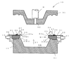
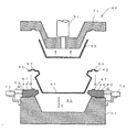
図1に示す本発明の一実施例に係る発泡成形型10は、キャビティ型11と、蓋型31とよりなる。前記キャビティ型11は、製品形状に合わせて窪んだキャビティ12が形成されている。前記キャビティ12は、蓋型側を除く周囲が壁部13で包囲されている。前記壁部13における蓋型31との重ね合わせ側(蓋型が重なる側)に、表皮一体発泡成形品の脱型方向E1と交差するキャビティ内外方向Q1へスライド可能なスライド型15が設けられている。前記スライド型15は、エアシリンダ装置やモータ駆動機構等からなるスライド駆動装置17によってスライド可能とされている。前記スライド型15をキャビティ内方へスライドさせることにより、前記スライド型15が前記キャビティ12内方へ突出して前記キャビティ12にアンダーカット形状(表皮一体発泡成形品の脱型を妨げる形状)を形成し(図1の右側のスライド型15aの状態)、一方、前記スライド型15をキャビティ外方へスライドさせることにより前記スライド型15がキャビティ12から引っ込んで(図1の左側のスライド型15bの状態)、前記アンダーカット形状を解消する。
A foam molding die 10 according to an embodiment of the present invention shown in FIG. 1 includes a cavity die 11 and a lid die 31. The cavity mold 11 is formed with a cavity 12 that is recessed according to the product shape. The cavity 12 is surrounded by a wall portion 13 except for the lid mold side. A
前記キャビティ型11の蓋型との重ね合わせ面27に、表皮端部係止プレート21が前記スライド型15の蓋型側表面と重なるように設けられている。なお、前記表皮端部係止プレート21において蓋型と対向する面が蓋型との重ね合わせ面27に相当する。本実施例の表皮端部係止プレート21は、固定側22とキャビティ内方端部側23がヒンジ25で連結され、前記キャビティ内方端部側23が前記ヒンジ25の位置から表皮一体発泡成形品の脱型方向E1へ回転可能となっている。
A skin end
前記表皮端部係止プレート21の固定側22は、前記キャビティ型11に固定され、前記キャビティ内方端部側23のみ表皮一体発泡成形品の脱型方向E1へ回転可能とされている。前記固定側22のキャビティ型11への固定は、図示の例では、キャビティ型11に固定されている前記スライド駆動装置17に固定されているが、キャビティ型11に直接固定されるようにしてもよい。なお、前記固定側22のキャビティ型11への固定は、前記スライド型15の前記スライドを妨げないものとされ、かつスライド型15のスライド時に前記表皮端部係止プレート21がスライドしないものとされる。
The fixed
前記表皮端部係止プレート21のキャビティ内方端部側23は、前記スライド型15がキャビティ外方側へスライドして前記スライド型15によるキャビティ形状解消状態(図1の左側のスライド型15bの状態)時に、前記キャビティ内方端部側23がキャビティ12内に突出した状態となるように長さ等が構成されている。また、本実施例では、前記スライド型15がキャビティ外方へスライドして前記キャビティ形状を解消した状態では、前記スライド型15の蓋型表面側に前記キャビティ内方端部側23のヒンジ25側部分が一部重なって前記スライド型15で支持され、前記表皮一体発泡成形品の脱型方向E1と交差するキャビティ内方へ向けて突出した状態で維持されるように構成されている。前記内方側端部23の表面には表皮端部係止用突部24が蓋型31へ向けて形成されている。前記表皮端部係止用突部24は、前記内方側端部23のキャビティ内方端23aに近付けて形成するのが、その後に切除される表皮端部を少なくできるためにより好ましい。
The cavity
蓋型31は、前記キャビティ12に蓋をするものであり、発泡体原料注入孔32が形成されている。前記発泡体原料注入孔32には、発泡体原料の注入装置における注入ヘッドHのノズルが挿入される。 The lid mold 31 covers the cavity 12 and has a foam material injection hole 32 formed therein. A nozzle of an injection head H in the foam material injection device is inserted into the foam material injection hole 32.
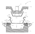
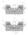
次に、前記発泡成形型10を用いる表皮一体発泡成形品の製造方法について説明する。まず、図2に示すように、前記蓋型31を前記キャビティ型11から離して成形型10を開けた状態とし、その状態で前記スライド型15をキャビティ内方へスライドさせて前記アンダーカット形状とした状態で表皮41を前記キャビティ12に配置して前記表皮の端部42に形成されている係止用凹部43を前記表皮端部係止プレート21の表皮端部係止用突部24に係止させる。また、図示の例では、基材51を前記蓋型31の型面35にクリップ等で保持する。前記基材51には前記蓋型31の発泡体原料注入孔32に位置を合わせて原料注入孔55が形成されている。
Next, the manufacturing method of the skin integral foam-molded product using the
その後、本実施例では、図3に示すように、前記キャビティ型11に蓋型31を重ねて成形型10を閉じる。これによって、前記表皮の端部42は、前記表皮端部係止プレート21と前記蓋型31間で挟持される。そして、前記注入ヘッドHからウレタンフォーム原料等の発泡体原料Pを表皮41と基材51とで区画された空間内に注入して発泡体58を形成し、発泡体形成時の接着性等で表皮41及び基材51と一体にして表皮発泡成形品59を形成する。
Thereafter, in this embodiment, as shown in FIG. 3, the lid mold 31 is stacked on the cavity mold 11 to close the
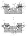
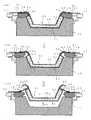
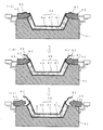
次いで、前記蓋型31を開けて、図4の(4A)のように、表皮一体発泡成形品59の基材51側を開放する。そして、図4の(4B)のように、前記スライド型15をキャビティ外方へスライドさせて、前記スライド型15によるキャビティ形状を解消する。これによって、前記表皮端部係止プレート21のキャビティ内方端部側23が前記スライド型15よりもキャビティ内方へ突出した状態となる。その状態で、前記表皮一体発泡成形品59の脱型を行う。前記脱型は、前記表皮一体発泡成形品59とキャビティ面との間へエアを吹き込むことにより表皮一体発泡成形品59を脱型方向へ浮き上がらせることにより、あるいは、図示しない突き出し部材をキャビティ型11に設けて前記突き出し部材によって表皮一体発泡成形品59を脱型方向へ押し出すこと等の方法によって行われる。前記脱型の際、図4の(4C)のように、前記表皮端部係止プレート21のキャビティ内方端部側23が前記表皮一体発泡成形品89により前記脱型方向E1へ押されて脱型方向へ回動し、前記表皮一体発泡成形品59の脱型を妨げることがない。脱型された表皮一体発泡成形品59は、表皮の端部42が切除されて製品とされる。
Next, the lid mold 31 is opened, and the base material 51 side of the skin-integrated foam-molded
なお、前記の実施例では、蓋型によってキャビティに蓋をした状態で発泡体原料をキャビティの表皮内に注入しているが、蓋型を開けた状態で発泡体原料をキャビティの表皮内に注入し、その後に蓋型を閉じるようにしてもよい。その場合、蓋型及び基材には、発泡体原料注入用の孔が不要となる。また、表皮一体発泡成形品の用途等によっては、前記基材が不要とされる場合もある。 In the above embodiment, the foam raw material is injected into the skin of the cavity with the lid closed by the lid mold, but the foam raw material is injected into the skin of the cavity with the lid open. Then, the lid mold may be closed thereafter. In that case, the hole for injecting the foam material becomes unnecessary in the lid mold and the base material. Moreover, the said base material may be made unnecessary depending on the use etc. of a skin integral foam molded product.
このように、本発明の表皮一体発泡成形品の製造方法及び発泡成形型によれば、スライド型のキャビティ外方へのスライドに先立って表皮端部の係止用凹部を表皮端部係止プレートの表皮端部係止用突部から外す必要がなく、脱型作業を容易に行うことができる。しかも、複雑な装置や高価な装置が不要なため、発泡成形型を安価にすることができる。さらに、表皮端部係止プレートに形成する表皮端部係止用突部を表皮端部係止プレートのキャビティ内方端部に近づけて設けることにより、表皮一体発泡成形品の脱型後に切除される非製品部分の表皮端部を少なくすることができ、材料費の削減及び廃棄物の低減を実現することができる。 Thus, according to the manufacturing method and foam molding die of the skin-integrated foam-molded product of the present invention, the skin-end locking plate is provided with the locking recess at the skin end prior to sliding outward of the slide mold cavity. It is not necessary to remove from the skin end portion locking projection, and the demolding operation can be easily performed. And since a complicated apparatus and an expensive apparatus are unnecessary, a foaming mold can be made cheap. Furthermore, by providing a skin edge locking projection formed on the skin edge locking plate close to the cavity inner end of the skin edge locking plate, the skin integrated foam molded product is removed after demolding. Therefore, it is possible to reduce the skin end portion of the non-product portion, and it is possible to reduce the material cost and the waste.
10 発泡成形型
11 キャビティ型
12 キャビティ
13 キャビティ型の壁部
15 スライド型
21 表皮端部係止プレート
23 表皮端部係止プレートのキャビティ内方端部側
24 表皮端部係止用突部
31 蓋型
41 表皮
42 表皮の端部
43 表皮端部の係止用凹部
E1 表皮一体発泡成形品の脱型方向
DESCRIPTION OF
Claims (2)
前記キャビティ型の前記キャビティ周囲の壁部における蓋型との重ね合わせ面に表皮の端部が位置するようにして前記表皮の端部間を前記キャビティに配置し、前記キャビティの表皮と前記蓋型間で発泡体を発泡体原料から発泡させて前記表皮と一体にした表皮一体発泡成形品を形成し、前記蓋型を開けて前記キャビティから前記表皮一体発泡成形品を脱型する表皮一体発泡成形品の製造方法において、
前記キャビティ型は、前記壁部における蓋型との重ね合わせ側に、表皮一体発泡成形品の脱型方向と交差するキャビティ内外方向へスライド可能なスライド型を設けて、前記スライド型をキャビティ内方へスライドさせることにより前記キャビティにアンダーカット形状を形成し、一方、前記スライド型をキャビティ外方へスライドさせることにより前記アンダーカット形状を解消するように構成すると共に、
表皮端部係止用突部が表面に形成された表皮端部係止プレートを表皮一体発泡成形品の脱型方向と交差するキャビティ内方へ向けて突出し、かつ前記スライド型の蓋型側表面と重なるように前記キャビティ型に設けて、前記スライド型がキャビティ外方へスライドして前記スライド型による前記キャビティのアンダーカット形状が解消された際に、前記表皮端部係止プレートのキャビティ内方端部側が前記スライド型よりもキャビティ内方へ突出状態となると共に、当該突出部分が表皮一体発泡成形品の脱型方向へ押された際に前記脱型方向へ回転可能に構成し、
前記スライド型をキャビティ内方へスライドさせて前記アンダーカット形状とした状態で前記表皮を前記キャビティに配置して前記表皮の端部に形成されている係止用凹部を前記表皮端部係止プレートの表皮端部係止用突部に係止し、
前記キャビティの表皮と前記蓋型間で前記発泡体を発泡体原料から発泡させて前記表皮と一体にした表皮一体発泡成形品を形成した後、前記蓋型を開けて前記スライド型をキャビティ外方へスライドさせて前記スライド型によるアンダーカット形状を解消し、前記キャビティから前記表皮一体発泡成形品を脱型する際に、前記スライド型よりも前記キャビティ内方へ突出している前記表皮端部係止プレートの突出部側を前記表皮一体発泡成形品によって前記表皮一体発泡成形品の脱型方向へ押して回転させながら前記表皮一体発泡成形品の脱型を行うことを特徴とする表皮一体発泡成形品の製造方法。 Using a foam mold that includes a cavity mold in which a cavity is formed and a lid mold that covers the cavity,
The end portion of the skin is disposed in the cavity so that the end portion of the skin is positioned on the overlapping surface of the cavity mold with the lid on the wall portion around the cavity, and the skin of the cavity and the lid die A foam integrated foam molding in which a foam is foamed from a foam raw material to form a skin integrated foam molded product integrated with the skin, and the lid mold is opened to release the skin integrated foam molded product from the cavity In the manufacturing method of goods,
The cavity mold is provided with a slide mold that is slidable inward and outward of the cavity that intersects the mold release direction of the skin-integrated foam-molded product on the side of the wall portion that overlaps the lid mold. The undercut shape is formed in the cavity by sliding to the other side, while the undercut shape is eliminated by sliding the slide mold outward from the cavity,
The skin end portion locking plate having a skin end portion locking projection formed on the surface protrudes inward of the cavity intersecting the demolding direction of the skin integrated foam molded product, and the lid side surface of the slide mold When the slide mold slides outward from the cavity and the undercut shape of the cavity due to the slide mold is eliminated, the cavity inner side of the skin end portion locking plate is provided. The end side is in a state of projecting inward of the cavity from the slide mold, and the projecting portion is configured to be rotatable in the demolding direction when pressed in the demolding direction of the skin-integrated foam molded product,
In the state in which the slide mold is slid inward into the cavity to form the undercut shape, the skin is disposed in the cavity and the locking recess formed at the end of the skin is the skin edge locking plate. Lock to the skin end locking protrusion of
The foam is foamed from a foam material between the skin of the cavity and the lid mold to form an integral foam-molded article integrated with the skin, and then the lid mold is opened to move the slide mold outward from the cavity. The undercut shape due to the slide mold is eliminated by sliding to the skin, and when the skin integral foam molded product is removed from the cavity, the skin end portion locking projecting inward of the cavity from the slide mold A skin-integrated foam-molded product, wherein the skin-integrated foam-molded product is demolded while the protruding portion side of the plate is rotated by pressing the skin-integrated foam-molded product in the mold release direction of the skin-integrated foam-molded product. Production method.
前記キャビティ型は、前記壁部における蓋型との重ね合わせ側に、表皮一体発泡成形品の脱型方向と交差するキャビティ内外方向へスライド可能なスライド型を設けて、前記スライド型をキャビティ内方へスライドさせることにより前記キャビティにアンダーカット形状を形成し、一方、前記スライド型をキャビティ外方へスライドさせることにより前記アンダーカット形状を解消するように構成すると共に、
表皮端部係止用突部が表面に形成された表皮端部係止プレートを表皮一体発泡成形品の脱型方向と交差するキャビティ内方へ向けて突出し、かつ前記スライド型の蓋型側表面と重なるように前記キャビティ型に設けて、前記スライド型がキャビティ外方へスライドして前記スライド型による前記キャビティのアンダーカット形状が解消された際に、前記表皮端部係止プレートのキャビティ内方端部側が前記スライド型よりもキャビティ内方へ突出状態となると共に、当該記突出部分が表皮一体発泡成形品の脱型方向へ押された際に前記脱型方向へ回転可能に構成したことを特徴とする発泡成形型。
Using a foam mold comprising a cavity mold in which a cavity is formed and a lid mold for covering the cavity, the end of the skin on the overlapping surface of the cavity mold with the lid mold around the cavity A skin-integrated foam-molded product in which the end portion of the skin is disposed in the cavity in such a manner that the foam is foamed from the foam material between the skin of the cavity and the lid mold so as to be integrated with the skin. In the molding die used in the method for manufacturing the skin-integrated foam-molded product, which opens the lid mold and demolds the skin-integrated foam-molded product from the cavity,
The cavity mold is provided with a slide mold that is slidable inward and outward of the cavity that intersects the mold release direction of the skin-integrated foam-molded product on the side of the wall portion that overlaps the lid mold. The undercut shape is formed in the cavity by sliding to the other side, while the undercut shape is eliminated by sliding the slide mold outward from the cavity,
The skin end portion locking plate having a skin end portion locking projection formed on the surface protrudes inward of the cavity intersecting the demolding direction of the skin integrated foam molded product, and the lid side surface of the slide mold When the slide mold slides outward from the cavity and the undercut shape of the cavity due to the slide mold is eliminated, the cavity inner side of the skin end portion locking plate is provided. The end side is in a state of projecting inward of the cavity from the slide mold, and the projecting portion is configured to be rotatable in the demolding direction when pressed in the demolding direction of the skin-integrated foam molded product. Characteristic foam mold.
Priority Applications (1)
| Application Number | Priority Date | Filing Date | Title |
|---|---|---|---|
| JP2008323274A JP2010143094A (en) | 2008-12-19 | 2008-12-19 | Method for manufacturing skin-integrated foam molded article and foam molding mold used for the same |
Applications Claiming Priority (1)
| Application Number | Priority Date | Filing Date | Title |
|---|---|---|---|
| JP2008323274A JP2010143094A (en) | 2008-12-19 | 2008-12-19 | Method for manufacturing skin-integrated foam molded article and foam molding mold used for the same |
Publications (1)
| Publication Number | Publication Date |
|---|---|
| JP2010143094A true JP2010143094A (en) | 2010-07-01 |
Family
ID=42564018
Family Applications (1)
| Application Number | Title | Priority Date | Filing Date |
|---|---|---|---|
| JP2008323274A Pending JP2010143094A (en) | 2008-12-19 | 2008-12-19 | Method for manufacturing skin-integrated foam molded article and foam molding mold used for the same |
Country Status (1)
| Country | Link |
|---|---|
| JP (1) | JP2010143094A (en) |
Cited By (5)
| Publication number | Priority date | Publication date | Assignee | Title |
|---|---|---|---|---|
| CN103862609A (en) * | 2012-12-12 | 2014-06-18 | 现代自动车株式会社 | Sealing apparatus for foam injection mold |
| KR101459846B1 (en) | 2012-12-12 | 2014-11-07 | 현대자동차주식회사 | Manufacturing apparatus and method of crash pad, and crash pad manufactured by the same |
| WO2015174076A1 (en) * | 2014-05-16 | 2015-11-19 | 株式会社ブリヂストン | Die and production method for molded article using die |
| KR102526972B1 (en) * | 2022-02-07 | 2023-04-27 | 이홍석 | Mat manufacturing mold for urethane foam puzzle mat and its manufacturing method |
| WO2025063042A1 (en) * | 2023-09-21 | 2025-03-27 | パナソニックIpマネジメント株式会社 | Press molding die, press device, method for manufacturing shaped article, and method for manufacturing molded article |
Citations (5)
| Publication number | Priority date | Publication date | Assignee | Title |
|---|---|---|---|---|
| JPH01127714U (en) * | 1988-02-19 | 1989-08-31 | ||
| JPH03106013U (en) * | 1990-02-16 | 1991-11-01 | ||
| JPH0576714U (en) * | 1992-03-24 | 1993-10-19 | 株式会社イノアックコーポレーション | Foam molding die skin material fixing structure |
| JPH0646920U (en) * | 1992-12-04 | 1994-06-28 | 株式会社イノアックコーポレーション | Foam molding die skin material fixing structure |
| JPH07308928A (en) * | 1994-05-18 | 1995-11-28 | Toyota Motor Corp | Mold |
-
2008
- 2008-12-19 JP JP2008323274A patent/JP2010143094A/en active Pending
Patent Citations (5)
| Publication number | Priority date | Publication date | Assignee | Title |
|---|---|---|---|---|
| JPH01127714U (en) * | 1988-02-19 | 1989-08-31 | ||
| JPH03106013U (en) * | 1990-02-16 | 1991-11-01 | ||
| JPH0576714U (en) * | 1992-03-24 | 1993-10-19 | 株式会社イノアックコーポレーション | Foam molding die skin material fixing structure |
| JPH0646920U (en) * | 1992-12-04 | 1994-06-28 | 株式会社イノアックコーポレーション | Foam molding die skin material fixing structure |
| JPH07308928A (en) * | 1994-05-18 | 1995-11-28 | Toyota Motor Corp | Mold |
Cited By (13)
| Publication number | Priority date | Publication date | Assignee | Title |
|---|---|---|---|---|
| CN103862609B (en) * | 2012-12-12 | 2017-09-01 | 现代自动车株式会社 | Sealing device for foam injection mold |
| KR101428274B1 (en) * | 2012-12-12 | 2014-08-07 | 현대자동차주식회사 | Sealing apparatus for foam-injection mold |
| KR101459846B1 (en) | 2012-12-12 | 2014-11-07 | 현대자동차주식회사 | Manufacturing apparatus and method of crash pad, and crash pad manufactured by the same |
| CN103862609A (en) * | 2012-12-12 | 2014-06-18 | 现代自动车株式会社 | Sealing apparatus for foam injection mold |
| WO2015174076A1 (en) * | 2014-05-16 | 2015-11-19 | 株式会社ブリヂストン | Die and production method for molded article using die |
| CN106457638A (en) * | 2014-05-16 | 2017-02-22 | 株式会社普利司通 | Die and production method for molded article using die |
| JP2015217581A (en) * | 2014-05-16 | 2015-12-07 | 株式会社ブリヂストン | Mold and manufacturing method of molded product using mold |
| CN106457638B (en) * | 2014-05-16 | 2018-11-06 | 株式会社普利司通 | The manufacturing method of the molded product of mold and the use mold |
| US10265888B2 (en) | 2014-05-16 | 2019-04-23 | Bridgestone Corporation | Mold and method of producing molded article using the mold |
| KR102526972B1 (en) * | 2022-02-07 | 2023-04-27 | 이홍석 | Mat manufacturing mold for urethane foam puzzle mat and its manufacturing method |
| KR20230119584A (en) * | 2022-02-07 | 2023-08-16 | 이홍석 | Mat manufacturing mold for urethane foam puzzle mat and its manufacturing method |
| KR102761948B1 (en) | 2022-02-07 | 2025-02-05 | (주)파크론 | Mat manufacturing mold for urethane foam puzzle mat and its manufacturing method |
| WO2025063042A1 (en) * | 2023-09-21 | 2025-03-27 | パナソニックIpマネジメント株式会社 | Press molding die, press device, method for manufacturing shaped article, and method for manufacturing molded article |
Similar Documents
| Publication | Publication Date | Title |
|---|---|---|
| JP2010143094A (en) | Method for manufacturing skin-integrated foam molded article and foam molding mold used for the same | |
| US20180222633A1 (en) | Method of Producing a Packaging Container with a Closure and Release Mechanism | |
| JP3943696B2 (en) | Manufacturing method of laminated molded product | |
| JP4106320B2 (en) | Injection molding method | |
| JP5349027B2 (en) | Two-layer foam molding method and apparatus | |
| JP5515335B2 (en) | Molding method and mold | |
| JP2007130966A (en) | Molding method and molding die for foamed resin molded product | |
| JP2004181687A (en) | Foaming mold and method for producing foamed molded article using the same | |
| JP4994004B2 (en) | Foam mold | |
| KR101310373B1 (en) | Epp foam-forming mold and mold using the same | |
| JP2011134860A (en) | Casing, and method and apparatus for manufacturing the same | |
| JP6496081B2 (en) | Molding method of resin foam with skin | |
| JP2006015633A (en) | Injection foam molding die, injection foam molding method and foamed resin member with skin | |
| JP4664105B2 (en) | Molding apparatus and molding method | |
| KR102431661B1 (en) | Double injection mold and method for vehicle interior materials | |
| JP5741933B2 (en) | Manufacturing method of resin molded products | |
| JP4832103B2 (en) | Method for producing foam integrated with skin having groove pattern | |
| JP5005464B2 (en) | Foam mold and method for producing foam molded member with skin | |
| JP5553398B2 (en) | Manufacturing method of foam molded article | |
| JP7684648B2 (en) | Manufacturing method of foam molded products | |
| JP2010017913A (en) | Injection molding mold and interior trim for vehicle | |
| JP2009119755A (en) | Skin molded product, method for molding skin molded product, and method for molding foam molded member with skin | |
| JP2011110726A (en) | Mold apparatus for injection molding | |
| JP2010115908A (en) | Method and apparatus for manufacturing foam molding member | |
| JPH0242418Y2 (en) |
Legal Events
| Date | Code | Title | Description |
|---|---|---|---|
| A621 | Written request for application examination |
Free format text: JAPANESE INTERMEDIATE CODE: A621 Effective date: 20111125 |
|
| A977 | Report on retrieval |
Free format text: JAPANESE INTERMEDIATE CODE: A971007 Effective date: 20130417 |
|
| A131 | Notification of reasons for refusal |
Free format text: JAPANESE INTERMEDIATE CODE: A131 Effective date: 20130423 |
|
| A02 | Decision of refusal |
Free format text: JAPANESE INTERMEDIATE CODE: A02 Effective date: 20130813 |