JP2010017913A - Injection molding mold and interior trim for vehicle - Google Patents
Injection molding mold and interior trim for vehicle Download PDFInfo
- Publication number
- JP2010017913A JP2010017913A JP2008179350A JP2008179350A JP2010017913A JP 2010017913 A JP2010017913 A JP 2010017913A JP 2008179350 A JP2008179350 A JP 2008179350A JP 2008179350 A JP2008179350 A JP 2008179350A JP 2010017913 A JP2010017913 A JP 2010017913A
- Authority
- JP
- Japan
- Prior art keywords
- interior material
- vehicle interior
- cavity
- submarine gate
- molding
- Prior art date
- Legal status (The legal status is an assumption and is not a legal conclusion. Google has not performed a legal analysis and makes no representation as to the accuracy of the status listed.)
- Pending
Links
Images


Abstract
Description
本発明は、サブマリンゲートを有する射出成形型および車両用内装材に関する。 The present invention relates to an injection mold having a submarine gate and a vehicle interior material.
従来、上下両型の型開きに伴ってゲートと成形品の接続部を自動的に切断するサブマリンゲートを有する射出成形型が知られている(下記特許文献1参照)。このような射出成形型によると、成形品を脱型した後に不要部分を手動で除去しなくて済むため、生産効率が高まるという効果がある。
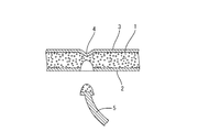
しかしながら、サブマリンゲートによって自動的に切断する方法では、図6に示すように、成形品1の裏面側2の一部を引きちぎるようにして切断するため、不要部分5を切断するに伴って成形品1の意匠面側3が凹んでしまい、凹み4が形成されてしまう不具合がある。
However, in the method of automatically cutting with the submarine gate, as shown in FIG. 6, a part of the
本発明は上記のような事情に基づいて完成されたものであって、サブマリンゲートを有する射出成形型において成形品の意匠面側の一部が凹むことを防ぐことを目的とする。 This invention is completed based on the above situations, Comprising: It aims at preventing a part by the side of the design surface of a molded article being dented in the injection mold which has a submarine gate.
本発明は、キャビティを構成する成形面に接続されたサブマリンゲートを有する射出成形型であって、サブマリンゲートの先端は、キャビティ内に成形された成形品を所定の厚みだけ厚肉化した厚肉部に接続されている構成としたところに特徴を有する。 The present invention relates to an injection mold having a submarine gate connected to a molding surface constituting a cavity, and the tip of the submarine gate has a thick wall formed by thickening a molded product formed in the cavity by a predetermined thickness. It is characterized in that it is configured to be connected to the part.
このような構成によると、型開きに伴ってサブマリンゲートの先端で成形品の一部が引きちぎられても、成形品が厚肉部の分だけ厚肉に形成されているため、成形品の意匠面側の一部が凹むことを防ぐことができる。 According to such a configuration, even if a part of the molded product is torn off at the tip of the submarine gate when the mold is opened, the molded product is formed as thick as the thick part. It is possible to prevent a part of the surface side from being recessed.
本発明の実施の態様として、以下の構成が好ましい。
成形面のうちサブマリンゲートの先端に接続された面には、厚肉部に対応して凹部が形成されている構成としてもよい。
The following configuration is preferable as an embodiment of the present invention.
It is good also as a structure by which the recessed part corresponding to the thick part is formed in the surface connected to the front-end | tip of a submarine gate among molding surfaces.
このような構成によると、サブマリンゲートの先端部に接続された部分のみを厚肉部とすればよいため、成形品全体を厚肉に形成しなくてもよく、成形品を成形するのに必要な樹脂量を必要最小限の量に留めることができる。 According to such a configuration, only the portion connected to the tip of the submarine gate needs to be a thick portion, so the entire molded product does not have to be thick, and is necessary for molding the molded product. The amount of resin required can be kept to the minimum necessary amount.
上記の射出成形型によって成形された車両用内装材であって、成形品は発泡成形されている構成としてもよい。すなわち、本発明は、車両用内装材を発泡成形する射出成形型に適用してもよい。 It is the vehicle interior material molded by the above injection mold, and the molded product may be formed by foam molding. In other words, the present invention may be applied to an injection mold for foaming a vehicle interior material.
本発明によれば、サブマリンゲートを有する射出成形型において成形品の意匠面側の一部が凹むことを防ぐことができる。 ADVANTAGE OF THE INVENTION According to this invention, it can prevent that a part by the side of the design surface of a molded article is dented in the injection mold which has a submarine gate.
<実施形態1>
本発明の実施形態1を図1ないし図4の図面を参照しながら説明する。図1は、本実施形態における射出成形型10を示す断面図であって、この射出成形型10は基台20を有し、基台20の上面には、下型40が設置されている。また、下型40の上方には上型30が設置され、上型30は、油圧シリンダ(図示せず)によって下型40に対して上下動可能とされている。また、上型30の上部には、射出装置60が設けられている。
<Embodiment 1>
Embodiment 1 of the present invention will be described with reference to the drawings of FIGS. FIG. 1 is a cross-sectional view showing an
この射出成形型10は、車両のドアトリムなどの車両用内装材50を成形する成形型であって、上下両型30,40を型閉じした状態では、上型30の下面と下型40の上面との間に車両用内装材50を成形するキャビティCが形成されている。キャビティCを構成する成形面のうち上側は、車両用内装材50の意匠面を成形する上側成形面C1とされ、キャビティCを構成する成形面のうち下側は、車両用内装材50の裏面を成形する下側成形面C2とされている。
The
上型30の内部には、射出装置60のノズル61から射出された溶融樹脂をキャビティC内に送り込むランナー31が配設されている。ランナー31の周囲には、加熱装置(図示せず)が設置されており、この加熱装置によってランナー31内の溶融樹脂が冷えて固まることを防止している。ランナー31の途中には、やや小径の制限ゲート32が設けられており、ランナー31は、制限ゲート32で二手に枝分かれして分流している。
Inside the
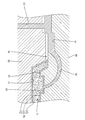
下型40は、左右一対からなるサブマリンゲート41を備えている。両サブマリンゲート41は、上下両型30,40が型閉じした状態では、二手に枝分かれした両ランナー31の先端とそれぞれ連通している。サブマリンゲート41は、先端にいくほど小径となるように形成されており、サブマリンゲート41の先端は、キャビティCに連通している。すなわち、サブマリンゲート41は、上下両型30,40のパーティングラインPLより下方に配置され、円弧状をなすカールホーン部42を通って下側成形面C2からキャビティC内に連通している。
The
下型40は、車両用内装材50の成形後にサブマリンゲート41内で冷えて固まった樹脂を除去するためのエジェクターピン(図示せず)を備えている。サブマリンゲート41内の樹脂は、上下両型30,40の型開きに伴ってエジェクターピンにより押し上げられる。このため、サブマリンゲート41内の樹脂は、キャビティC内の車両用内装材50との接続部分が切断されてカールホーン部42内に引き込まれる。したがって、車両用内装材50の脱型後に、車両用内装材50とそれ以外の不要部分(ランナー31やサブマリンゲート41内の樹脂)56を手動で切断しなくてもよい。
さて、本実施形態の車両用内装材50は、発泡成形によって形成されている。具体的には車両用内装材50は、ポリプロピレンなどの熱可塑性樹脂に添加された発泡剤を発泡させることによって形成されている。発泡成形によって車両用内装材50を成形すると、少ない樹脂量で車両用内装材50を成形することができることに加えて、車両用内装材50を軽量化することができるメリットがある。
Now, the
しかし、成形直後の車両用内装材50は、完全には固まっていないため、上下両型30,40の型開き時に不要部分56をカールホーン部42内に引き込んだ際に車両用内装材50の表面層51のみならず、内部の発泡層52までもが引きちぎられてしまう。このとき、車両用内装材50の厚みが薄い場合には、不要部分56の引き込みに伴って発泡層52が引っ張られて車両用内装材50の意匠面側53の一部が凹んでしまうおそれがある。
However, since the vehicle
その対策として、本実施形態の車両用内装材50は、サブマリンゲート41の先端との接続部分に厚肉部54を備えている。この厚肉部54は、1mm(好ましくは1〜2mm程度)とされている。すなわち、厚肉部54は、キャビティC内に成形された車両用内装材50を1mmだけ厚肉化したものであり、この厚肉部54にサブマリンゲート41の先端が接続されている。また、下側成形面C2には、厚肉部54に対応して凹部43が形成されている。
As a countermeasure, the vehicle
また、車両用内装材50のうち厚肉部54の形成されていない部分は、発泡前(図2の状態)の厚みが2mmで、発泡後(図3の状態)の厚みが3mmとなっている。すなわち、厚肉部54が形成されている車両用内装材50の厚みは、発泡前が3mmで発泡後が4mmとされている。このようにすれば、図4に示すように、不要部分56に引っ張られて発泡層52の一部が引きちぎられたとしても、厚肉部54の部分で対応するため、車両用内装材50の意匠面側53の一部が凹むことを防ぐことができる。
Further, the portion of the vehicle
本実施形態は以上のような構造であって、続いてその作用を説明する。本実施形態の車両用内装材50の製造方法は、上下両型30,40が型閉じした状態において上下両型30,40の間に形成されたキャビティC内に発泡剤が添加された溶融樹脂を射出して成形する工程(射出成形工程)と、上下両型30,40を閉じてから所定時間経過後に、上下両型30,40を所定の距離だけ開くことによって、キャビティC内に射出された溶融樹脂を発泡成形させる工程(発泡成形工程)と、上下両型30,40の型開きに伴って車両用内装材50が脱型されるとともに不要部分56が自動で切断される工程(脱型工程)とを有している。以下、これら3つの工程について、図2ないし図4の図面を参照しながら説明する。
The present embodiment has the above-described structure, and the operation thereof will be described subsequently. The manufacturing method of the vehicle
<射出成形工程>
図2に示すように、射出成形工程では、上下両型30,40が型閉じした状態で、射出装置60のノズル61からランナー31、サブマリンゲート41を通ってキャビティC内に発泡剤が添加された溶融樹脂を充填する。ランナー31内の樹脂は、加熱装置によって溶融状態に保たれるものの、サブマリンゲート41の樹脂は、冷却されて固化する。また、キャビティC内の樹脂のうち、表面側はある程度冷却されて固化することにより表面層51を構成しているものの、内部側は未だに溶融状態であり発泡前の発泡層52を構成している。
<Injection molding process>
As shown in FIG. 2, in the injection molding process, the foaming agent is added into the cavity C from the
<発泡成形工程>
図3に示すように、発泡成形工程では、上下両型30,40を閉じてから所定時間経過後に、上下両型30,40を所定の距離だけ開くことによってキャビティC内に射出された溶融樹脂を発泡させて車両用内装材50を成形する。具体的には、上下両型30,40が型閉じした状態では、キャビティC内に射出された溶融樹脂に圧力が作用し、溶融樹脂の熱によって溶融樹脂に添加されている発泡剤の反応が促進される。そして、所定時間経過後に、上下両型30,40を1mm程度開くことによって、キャビティCの内圧が低下し、溶融樹脂が発泡して発泡層52が形成される。このとき、発泡層52を囲む表面層51は冷えて固化されているため、発泡が抑制される。
<Foam molding process>
As shown in FIG. 3, in the foam molding process, the molten resin injected into the cavity C by opening the upper and
<脱型工程>
発泡成形の後、車両用内装材50を冷却し、上下両型30,40をさらに開くとともに、下型40のエジェクターピンが不要部分56を押し出してカールホーン部42内に引き込むことにより、車両用内装材50と不要部分56が自動で切断される。このとき、不要部分56は、図4に示すように、厚肉部54の一部を引きちぎって切断されるため、厚肉部54の内部には空洞55が形成される。このとき、空洞55の上部は、3mm程度の厚みを有しかつ剛性が確保されているため、車両用内装材50の意匠面側53の一部が凹むことを防ぐことができる。
<Demolding process>
After foam molding, the
以上のように本実施形態では、サブマリンゲート41の先端に凹部43を設けて厚肉部54を成形するようにしたから、車両用内装材50と不要部分56を自動で切断する際に車両用内装材50の意匠面側53の一部が凹むことを防ぐことができる。また、下側成形面C2のうち厚肉部54に対応して凹部43を設けたから、車両用内装材50の全体を厚肉にしなくてもよく、車両用内装材50を成形するのに必要な樹脂量を必要最小限の量に留めることができる。
As described above, in the present embodiment, the
<実施形態2>
次に、本発明の実施形態2を図5の図面を参照しながら説明する。本実施形態の射出成形型70は、実施形態1の射出成形型10とは異なり、ランナー31を備えておらず、左右一対からなる射出装置60を備えている。両射出装置60のノズル61は、パーティングラインPLに沿って配置されている。したがって、両射出装置60のノズル61から射出された溶融樹脂は、パーティングラインPLに沿ってサブマリンゲート41内に進入し、カールホーン部42を通ってキャビティC内に射出される。このようにすると、両射出装置60のノズル61からキャビティCまでの距離を短くすることができるとともに、キャビティC内に充填される溶融樹脂の内圧をより高めることができる。また、ランナー31を設けなくてよいから、ランナー31内に残された溶融樹脂を加熱する加熱装置を設けなくてもよい。
<
Next,
<他の実施形態>
本発明は上記記述及び図面によって説明した実施形態に限定されるものではなく、例えば次のような実施形態も本発明の技術的範囲に含まれる。
(1)本実施形態では厚肉部54の厚みとして1〜2mm程度が好ましいとしているものの、本発明によると、厚肉部54の厚みは、車両用内装材50の材料や製造条件によって適宜変更可能である。要するに、脱型時に発泡層52の一部が引きちぎられて空洞55が形成された際に、空洞55の上部が、車両用内装材50の意匠面側53の一部を凹ませない程度の剛性を有していればよい。
<Other embodiments>
The present invention is not limited to the embodiments described with reference to the above description and drawings. For example, the following embodiments are also included in the technical scope of the present invention.
(1) In the present embodiment, the thickness of the
(2)本実施形態では下側成形面C2の一部に凹部43を形成しているものの、本発明によると、下側成形面C2の全体に凹部43を形成し、車両用内装材50の全体を厚肉に形成してもよい。
(2) Although the
(3)本実施形態では車両用内装材50を発泡成形する射出成形型10を例示しているものの、本発明によると、車両用内装材50を発泡させないで成形する通常の射出成形型に適用してもよい。
(3) Although the present embodiment illustrates the
(4)本実施形態の射出成形型は上下方向に設置され、型閉じ、型開き動作は上下方向の移動で行っているものの、本発明によると、射出成形型を水平方向に設置してもよく、その場合の型閉じ、型開き動作は水平方向の移動で行ってもよい。 (4) Although the injection mold of this embodiment is installed in the vertical direction and the mold closing and mold opening operations are performed by moving in the vertical direction, according to the present invention, the injection mold is installed in the horizontal direction. In this case, the mold closing and mold opening operations may be performed by moving in the horizontal direction.
10…射出成形型
30…上型
40…下型
41…サブマリンゲート
43…凹部
50…車両用内装材
54…厚肉部
56…不要部分
70…射出成形型
C…キャビティ
C1…上側成形面
C2…下側成形面
DESCRIPTION OF
Claims (3)
前記サブマリンゲートの先端は、前記キャビティ内に成形された成形品を所定の厚みだけ厚肉化した厚肉部に接続されていることを特徴とする射出成形型。 An injection mold having a submarine gate connected to a molding surface constituting a cavity,
An injection mold, wherein a tip of the submarine gate is connected to a thick portion obtained by thickening a molded product molded in the cavity by a predetermined thickness.
Priority Applications (1)
| Application Number | Priority Date | Filing Date | Title |
|---|---|---|---|
| JP2008179350A JP2010017913A (en) | 2008-07-09 | 2008-07-09 | Injection molding mold and interior trim for vehicle |
Applications Claiming Priority (1)
| Application Number | Priority Date | Filing Date | Title |
|---|---|---|---|
| JP2008179350A JP2010017913A (en) | 2008-07-09 | 2008-07-09 | Injection molding mold and interior trim for vehicle |
Publications (1)
| Publication Number | Publication Date |
|---|---|
| JP2010017913A true JP2010017913A (en) | 2010-01-28 |
Family
ID=41703278
Family Applications (1)
| Application Number | Title | Priority Date | Filing Date |
|---|---|---|---|
| JP2008179350A Pending JP2010017913A (en) | 2008-07-09 | 2008-07-09 | Injection molding mold and interior trim for vehicle |
Country Status (1)
| Country | Link |
|---|---|
| JP (1) | JP2010017913A (en) |
Cited By (2)
| Publication number | Priority date | Publication date | Assignee | Title |
|---|---|---|---|---|
| DE102017107315A1 (en) | 2016-04-08 | 2017-10-12 | Toyota Boshoku Kabushiki Kaisha | METHOD FOR PRODUCING A FORM, FORM AND AN INNER COMPONENT OF A VEHICLE |
| CN115447114A (en) * | 2022-08-23 | 2022-12-09 | 浙江艾森新材料股份有限公司 | Device and process for manufacturing automotive interior material |
Citations (5)
| Publication number | Priority date | Publication date | Assignee | Title |
|---|---|---|---|---|
| JPH01125614U (en) * | 1988-02-09 | 1989-08-28 | ||
| JPH0453717A (en) * | 1990-06-22 | 1992-02-21 | Takata Kk | Method for molding module cover of air bag device |
| JPH05104584A (en) * | 1991-10-17 | 1993-04-27 | Takata Kk | Molding method of module cover for air bag device |
| JPH07290497A (en) * | 1994-04-26 | 1995-11-07 | Toyoda Gosei Co Ltd | Method and mold apparatus for molding resin product |
| JP2009034970A (en) * | 2007-08-03 | 2009-02-19 | Canon Inc | Molded article and electronic device |
-
2008
- 2008-07-09 JP JP2008179350A patent/JP2010017913A/en active Pending
Patent Citations (5)
| Publication number | Priority date | Publication date | Assignee | Title |
|---|---|---|---|---|
| JPH01125614U (en) * | 1988-02-09 | 1989-08-28 | ||
| JPH0453717A (en) * | 1990-06-22 | 1992-02-21 | Takata Kk | Method for molding module cover of air bag device |
| JPH05104584A (en) * | 1991-10-17 | 1993-04-27 | Takata Kk | Molding method of module cover for air bag device |
| JPH07290497A (en) * | 1994-04-26 | 1995-11-07 | Toyoda Gosei Co Ltd | Method and mold apparatus for molding resin product |
| JP2009034970A (en) * | 2007-08-03 | 2009-02-19 | Canon Inc | Molded article and electronic device |
Cited By (4)
| Publication number | Priority date | Publication date | Assignee | Title |
|---|---|---|---|---|
| DE102017107315A1 (en) | 2016-04-08 | 2017-10-12 | Toyota Boshoku Kabushiki Kaisha | METHOD FOR PRODUCING A FORM, FORM AND AN INNER COMPONENT OF A VEHICLE |
| US10954601B2 (en) | 2016-04-08 | 2021-03-23 | Toyota Boshoku Kabushiki Kaisha | Method of producing die, die, and interior component of vehicle |
| CN115447114A (en) * | 2022-08-23 | 2022-12-09 | 浙江艾森新材料股份有限公司 | Device and process for manufacturing automotive interior material |
| CN115447114B (en) * | 2022-08-23 | 2023-05-02 | 浙江艾森新材料股份有限公司 | Automobile interior material manufacturing device and process |
Similar Documents
| Publication | Publication Date | Title |
|---|---|---|
| JPH03254919A (en) | Manufacture of module cover of air bag | |
| JP6658472B2 (en) | Foam molding | |
| JP2014121793A (en) | Method for producing under cover for vehicle and under cover for vehicle | |
| JP2010017913A (en) | Injection molding mold and interior trim for vehicle | |
| JP5341720B2 (en) | Foam molding equipment | |
| JP5187216B2 (en) | Mold for counter pressure method | |
| JP4476673B2 (en) | Mold for foam molding | |
| JP2005178185A (en) | Injection molding mold and method for producing injection-molded article using the mold | |
| JP5810964B2 (en) | Molding method of resin molded products | |
| JP4106320B2 (en) | Injection molding method | |
| JP2005288745A (en) | Method for producing injection-molded article | |
| JP6057327B2 (en) | Injection molding equipment | |
| JP6725832B2 (en) | Molding method | |
| JP2007261186A (en) | Injection molding method for resin molding product and injection mold | |
| JP2005193634A (en) | Injection-molded product manufacturing method and mold assembly therefor | |
| JP6322018B2 (en) | Injection mold and method of manufacturing resin molded product using the same | |
| JP5553398B2 (en) | Manufacturing method of foam molded article | |
| JP2009226784A (en) | Method and apparatus for forming resin molded article | |
| JP2011025452A (en) | Foaming mold and method for manufacturing foam molded article | |
| CN109070402A (en) | The molding machine of the forming method of instrument board, instrument board and instrument board | |
| JP2006015633A (en) | Injection foaming mold, injection foam molding method and skinned foamed resin member | |
| JP2004174778A (en) | Resinous article with bottomed channel, its manufacturing method and manufacturing apparatus therefor | |
| JP2007130845A (en) | Method for molding foamable resin and structure of mold | |
| JP4254210B2 (en) | Manufacturing method and manufacturing apparatus for resinous object having bottomed groove | |
| JP2003191298A (en) | Method for manufacturing injection-molded object with thin part and mold |
Legal Events
| Date | Code | Title | Description |
|---|---|---|---|
| RD02 | Notification of acceptance of power of attorney |
Free format text: JAPANESE INTERMEDIATE CODE: A7422 Effective date: 20091022 |
|
| RD04 | Notification of resignation of power of attorney |
Effective date: 20091022 Free format text: JAPANESE INTERMEDIATE CODE: A7424 |
|
| A621 | Written request for application examination |
Free format text: JAPANESE INTERMEDIATE CODE: A621 Effective date: 20110218 |
|
| A977 | Report on retrieval |
Effective date: 20120801 Free format text: JAPANESE INTERMEDIATE CODE: A971007 |
|
| A131 | Notification of reasons for refusal |
Effective date: 20120816 Free format text: JAPANESE INTERMEDIATE CODE: A131 |
|
| A02 | Decision of refusal |
Effective date: 20121204 Free format text: JAPANESE INTERMEDIATE CODE: A02 |