JP2010143086A - Mold for tire - Google Patents
Mold for tire Download PDFInfo
- Publication number
- JP2010143086A JP2010143086A JP2008323144A JP2008323144A JP2010143086A JP 2010143086 A JP2010143086 A JP 2010143086A JP 2008323144 A JP2008323144 A JP 2008323144A JP 2008323144 A JP2008323144 A JP 2008323144A JP 2010143086 A JP2010143086 A JP 2010143086A
- Authority
- JP
- Japan
- Prior art keywords
- groove
- mold
- piece
- tire
- less
- Prior art date
- Legal status (The legal status is an assumption and is not a legal conclusion. Google has not performed a legal analysis and makes no representation as to the accuracy of the status listed.)
- Pending
Links
Images


Landscapes
- Moulds For Moulding Plastics Or The Like (AREA)
Abstract
【課題】タイヤにベアーが生じにくく、かつ容易に製作されうるタイヤ用モールドの提供。
【解決手段】モールドのセグメント4は、ブロック12を備えている。このブロック12は、多数のピース20からなる。ピース20の上面26には、多数の溝30が形成されている。この上面26は、粗面である。溝30の断面形状は、矩形である。溝30の一端は、キャビティ面に露出している。溝30は、モールドの半径方向に延びている。溝30の他端は、ピース20の背面に露出している。溝30は、0.01mm以上0.10mm以下の深さと、0.01mm以上0.10mm以下の幅とを有する。溝30と、この溝30に隣接する他の溝30とのピッチは、0.10mm以上20mm以下である。加硫工程において、ローカバーとキャビティ面との間のエアーは、溝30を通じて排出される。
【選択図】図4Provided is a tire mold that is less likely to bear on a tire and can be easily manufactured.
A segment 4 of a mold includes a block 12. The block 12 includes a number of pieces 20. A large number of grooves 30 are formed on the upper surface 26 of the piece 20. The upper surface 26 is a rough surface. The cross-sectional shape of the groove 30 is a rectangle. One end of the groove 30 is exposed on the cavity surface. The groove 30 extends in the radial direction of the mold. The other end of the groove 30 is exposed on the back surface of the piece 20. The groove 30 has a depth of 0.01 mm or more and 0.10 mm or less and a width of 0.01 mm or more and 0.10 mm or less. The pitch between the groove 30 and another groove 30 adjacent to the groove 30 is 0.10 mm or more and 20 mm or less. In the vulcanization process, air between the raw cover and the cavity surface is discharged through the groove 30.
[Selection] Figure 4
Description
本発明は、タイヤの加硫工程に用いられるモールドに関する。詳細には、本発明は、エアーの排出のための隙間を有するモールドに関する。 The present invention relates to a mold used in a tire vulcanization process. Specifically, the present invention relates to a mold having a gap for discharging air.
タイヤの加硫工程では、モールドが用いられている。割モールド及びツーピースモールドが、この加硫工程に用いられうる。加硫工程では、予備成形されたローカバーが、モールドに投入される。このローカバーは、モールドとブラダーとに囲まれたキャビティにおいて、加圧されつつ加熱される。加圧と加熱とにより、ローカバーのゴム組成物がキャビティ内を流動する。加熱によりゴムが架橋反応を起こし、タイヤが得られる。加圧の際、モールドのキャビティ面とローカバーとの間にエアーが残留すると、タイヤの表面にベアーが形成される。ベアーは、タイヤの品質を低下させる。一般的なモールドは、ベントホールを有している。このベントホールを通じて、エアーが排出される。 In the tire vulcanization process, a mold is used. A split mold and a two-piece mold can be used for this vulcanization process. In the vulcanization process, a preformed raw cover is put into a mold. The raw cover is heated while being pressurized in a cavity surrounded by the mold and the bladder. The rubber composition of the raw cover flows in the cavity by pressurization and heating. The rubber causes a crosslinking reaction by heating, and a tire is obtained. When air is left between the cavity surface of the mold and the raw cover during pressurization, a bear is formed on the surface of the tire. Bears reduce tire quality. A general mold has a vent hole. Air is discharged through the vent hole.
割モールドは、円弧状のトレッドセグメントを備えている。多数のセグメントが並べられることで、リング状のキャビティ面が形成される。セグメントは、鋳型が用いられた重力鋳造又は低圧鋳造によって得られる。金属製鋳型が用いられた精密鋳造(いわゆるダイキャスト)により、セグメントが得られることもある。 The split mold includes an arc-shaped tread segment. A ring-shaped cavity surface is formed by arranging a large number of segments. The segments are obtained by gravity casting or low pressure casting using a mold. A segment may be obtained by precision casting (so-called die casting) using a metal mold.
セグメントの、隣接するセグメントに当接する面は、「分割面」と称されている。分割面とこの分割面に隣接する他の分割面との間には、微小な間隙が生じる。この間隙を通じて、エアーが排出される。この排出により、ベアーが防止される。 A surface of a segment that contacts an adjacent segment is referred to as a “divided surface”. A minute gap is generated between the dividing surface and another dividing surface adjacent to the dividing surface. Air is discharged through this gap. This discharge prevents bears.
特開平2−295706号公報、特開2005−225094公報及び特表2006−508833公報には、キャビティ面にスリットを有するタイヤ用モールドが開示されている。このモールドでは、スリットを介してエアーが排出される。 JP-A-2-295706, JP-A-2005-225094, and JP-T-2006-508833 disclose a tire mold having a slit on a cavity surface. In this mold, air is discharged through the slit.
特開2007−144997公報、特開2007−237708公報及び特開2008−87428公報には、第一金属片と第二金属片とを有するタイヤ用モールドが開示されている。このモールドでは、隣接する2つの第一金属片の間に溶融金属が流し込まれる。この金属が凝固することで、第二金属片が形成される。このモールドでは、第一金属片と第二金属片との間のスリットを介してエアーが排出される。
ベントホールを有するモールドでは、このベントホールにゴム組成物が流入し、スピューが生じる。スピューは、タイヤの外観を損なう。スピューは切削によって除去されうるが、この切削には手間がかかる。架橋反応を起こしたゴム組成物が、ベントホールに残存することもある。残存によりエアーの排出が阻害され、ベアーが生じる。ベアー抑制の目的で、ベントホールのクリーニングがなされる。このクリーニングには、手間がかかる。 In a mold having a vent hole, the rubber composition flows into the vent hole and spew occurs. Spew detracts from the appearance of the tire. Spew can be removed by cutting, but this cutting takes time. The rubber composition that has undergone a crosslinking reaction may remain in the vent hole. The remaining air hinders the discharge of air and causes a bear. The vent hole is cleaned for the purpose of restraining the bear. This cleaning takes time.
分割面同士の間隙を通じてエアーが排出されるモールドでは、分割面の近傍のエアーは十分に排出される。しかし、分割面から遠い箇所では、エアーの残留が原因でベアーが発生しやすい。 In the mold in which air is discharged through the gap between the divided surfaces, the air in the vicinity of the divided surfaces is sufficiently discharged. However, bears are likely to occur at locations far from the dividing surface due to residual air.
スリットを有するモールドでは、スリットの幅の調整に手間がかかる。さらに、このモールドが繰り返し使用されることにより、スリットを挟んで存在する金属ピース同士が密着することがある。密着が生じたモールドでは、エアーの排出が十分にはなされない。不十分な排出は、ベアーの発生を招来する。 In a mold having a slit, it takes time to adjust the width of the slit. Furthermore, when this mold is used repeatedly, the metal pieces existing across the slit may be in close contact with each other. In the mold with close contact, air is not sufficiently discharged. Insufficient discharge leads to the generation of bears.
本発明の目的は、タイヤにベアーが生じにくく、かつ容易に製作されうるタイヤ用モールドの提供にある。 An object of the present invention is to provide a mold for a tire that is less likely to bear on a tire and can be easily manufactured.
本発明に係るタイヤ用モールドは、重ねられた多数のピースを備える。それぞれのピースの内面は、キャビティ面を形成する。このピースの、他のピースと当接する面は、粗面である。 The tire mold according to the present invention includes a large number of stacked pieces. The inner surface of each piece forms a cavity surface. The surface of this piece that comes into contact with another piece is a rough surface.
好ましくは、ピースは、他のピースと当接する面に、多数の溝を備える。好ましくは、それぞれの溝の一端は、キャビティ面に露出する。好ましくは、この溝は、モールドの半径方向に沿って延びる。好ましくは、この溝は、0.01mm以上0.10mm以下の深さと、0.01mm以上0.10mm以下の幅とを有する。好ましくは、この溝と、この溝に隣接する他の溝とのピッチは、0.10mm以上20mm以下である。 Preferably, the piece includes a large number of grooves on a surface that comes into contact with another piece. Preferably, one end of each groove is exposed to the cavity surface. Preferably, this groove extends along the radial direction of the mold. Preferably, the groove has a depth of 0.01 mm or more and 0.10 mm or less and a width of 0.01 mm or more and 0.10 mm or less. Preferably, the pitch between this groove and another groove adjacent to this groove is 0.10 mm or more and 20 mm or less.
本発明に係るタイヤ製造方法は、
(1)予備成形によってローカバーが得られる工程、
(2)並列された多数のピースを備えており、それぞれのピースの内面がキャビティ面を形成しており、このピースの他のピースと当接する面が粗面であるモールドに、上記ローカバーが投入される工程
及び
(3)このローカバーがモールド内で加圧及び加熱される工程
を含む。
The tire manufacturing method according to the present invention includes:
(1) A process in which a raw cover is obtained by preforming,
(2) The row cover is put into a mold having a large number of pieces arranged in parallel, the inner surface of each piece forming a cavity surface, and the surface in contact with the other piece of this piece is a rough surface. And (3) the raw cover is pressed and heated in the mold.
本発明に係るモールドでは、ピースと、このピースと隣接する他のピースとの隙間を通じてエアーが排出される。このモールドでは、ピースが他のピースと密着しても、排出がなされる。このモールドが繰り返し使用されても、ベアーが生じにくい。 In the mold according to the present invention, air is discharged through a gap between the piece and another piece adjacent to the piece. In this mold, even if a piece is in close contact with other pieces, the mold is discharged. Even if this mold is repeatedly used, bears are hardly generated.
以下、適宜図面が参照されつつ、好ましい実施形態に基づいて本発明が詳細に説明される。 Hereinafter, the present invention will be described in detail based on preferred embodiments with appropriate reference to the drawings.
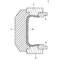
図1は、本発明の一実施形態に係るタイヤ用モールド2の一部が示された平面図である。図2は、図1のII−II線に沿った拡大断面図である。このモールド2は、多数のトレッドセグメント4と、上下一対のサイドプレート6と、上下一対のビードリング8とを備えている。セグメント4の平面形状は、実質的に円弧状である。多数のセグメント4が、リング状に配置されている。セグメント4の数は、通常3以上20以下である。サイドプレート6及びビードリング8は、実質的にリング状である。このモールド2は、いわゆる「割モールド」である。
FIG. 1 is a plan view showing a part of a
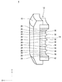
図3は、図1のモールド2のセグメント4が示された斜視図である。図4は、図3のセグメント4が示された正面図である。図3において、X方向は半径方向であり、Y方向は軸方向である。図4において、Z方向は周方向である。図4には、半径方向内側から見られたセグメント4が示されている。
FIG. 3 is a perspective view showing the
このセグメント4は、ホルダー10とブロック12とからなる。ホルダー10は、鋼又はアルミニウム合金からなる。ブロック12は、ホルダー10に装着されてる。ブロック12は、図示されないボルトにより、ホルダー10に固定されている。ホルダー10に、周方向に並列された複数のブロックが装着されてもよい。
The
図3に示されるように、ブロック12はキャビティ面14を備えている。このキャビティ面14は、突出部16と凹陥部18とを備えている。突出部16と凹陥部18とにより、キャビティ面14に凹凸模様が形成されている。この突出部16は、タイヤのトレッドの溝に対応する。この突出部16及び凹陥部18により、タイヤにトレッドパターンが形成される。突出部16及び凹陥部18の形状は、トレッドパターンに応じて、適宜決定される。なお図2では、突出部16及び凹陥部18の図示が省略されている。
As shown in FIG. 3, the
図3及び4に示されるように、ブロック12は多数のピース20からなる。この実施形態では、ブロック12は15枚のピース20を備えている。ピース20の数は、適宜決定される。これらピース20は、軸方向において重ねられている。ブロック12が、周方向に重ねられたピースを備えてもよい。それぞれのピース20は、板状である。ピース20は、他のピース20と当接している。このピース20は、金属材料からなる。典型的な金属材料は、アルミニウム合金である。
As shown in FIGS. 3 and 4, the
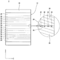
図5は、図3のセグメント4のピース20の一部が示された斜視図である。図6は、図5のピース20の一部が示された拡大断面図である。このピース20は、キャビティ面14、背面22、側面24、上面26及び底面28を備えている。図4から明らかなように、ピース20の上面26は他のピース20の底面28と当接している。
FIG. 5 is a perspective view showing a part of the
図5及び6に示されるように、上面26には多数の溝30が形成されている。この上面26は、粗面である。溝30の断面形状は、矩形である。溝30の一端32は、キャビティ面14に露出している(図4も参照)。溝30は、モールド2の半径方向に延びている。溝30の他端34は、背面22に露出している。溝30は、レーザービーム加工によって形成されうる。工具が用いられた切削により、溝30が形成されてもよい。溝30に代えて、触刻によって粗面が達成されてもよい。
As shown in FIGS. 5 and 6, a number of
このモールド2が用いられたタイヤ製造方法では、予備成形によってローカバー(未加硫タイヤ)が得られる。このローカバーが、モールド2が開いておりブラダーが収縮している状態で、モールド2に投入される。モールド2が締められ、ブラダーが膨張する。ローカバーはブラダーによってモールド2のキャビティ面14に押しつけられ、加圧される。この状態のローカバー36が、図2に示されている。同時にローカバー36は、加熱される。加圧と加熱とによりゴム組成物が流動する。加熱によりゴムが架橋反応を起こし、タイヤが得られる。ローカバー36が加圧及び加熱される工程は、加硫工程と称される。ブラダーに代えて、中子が用いられてもよい。
In the tire manufacturing method using this
前述の通り、溝30はキャビティ面14に露出しているので、加硫工程において、ローカバー36とキャビティ面14との間のエアーは溝30を通じて排出される。エアーの排出により、ベアーが防止される。ピース20の上面26と、他のピース20の底面28とが密着した場合でも、溝30によりエアーの通路が確保される。このモールド2では、ベントホールが設けられなくても、十分にエアーが排出されうる。ベントホールを有さないモールド2により、スピューがないタイヤが得られる。このタイヤは、外観及び初期グリップ性能に優れる。溝30と共に、少数のベントホールが設けられてもよい。
As described above, since the
このモールド2では、ピース20と他のピース20との隙間の調整が不要である。このモールド2のメンテナンスは、容易である。
In the
キャビティ面14に凹凸模様が形成されなくてもよい。凹凸模様を有さないモールド2により、スリックタイヤ又はプレーンタイヤが得られうる。このスリックタイヤ及びプレーンタイヤでも、スピューが抑制される。このプレーンタイヤの表面がカットされて、凹凸模様が形成される。スピューが少ないので、このプレーンタイヤのカットは容易である。
Irregular patterns may not be formed on the
図6において矢印Dで示されているのは、溝30の深さである。エアーが十分に排出されるとの観点から、深さDは0.01mm以上が好ましく、0.03mm以上が特に好ましい。溝30に起因するスピューが生じにくいとの観点から、深さDは0.10mm以下が好ましく、0.07mm以下が特に好ましい。
In FIG. 6, what is indicated by an arrow D is the depth of the
図6において矢印Wで示されているのは、溝30の幅である。エアーが十分に排出されるとの観点から、幅Wは0.01mm以上が好ましく、0.03mm以上が特に好ましい。溝30に起因するスピューが生じにくいとの観点から、幅Wは0.10mm以下が好ましく、0.07mm以下が特に好ましい。
In FIG. 6, what is indicated by an arrow W is the width of the
深さ又は幅が変化する溝が形成されてもよい。キャビティ面14における深さ及び幅が小さく、背面22の近傍で深さ及び幅が大きな溝が好ましい。キャビティ面14における深さD及び幅Wが小さな溝により、この溝に起因するスピューの発生が抑制される。この溝では、キャビティ面14において測定された深さD及び幅Wが、上記範囲内に設定される。
Grooves with varying depth or width may be formed. A groove having a small depth and width in the
図6において矢印Pで示されているのは、溝30のピッチである。加工の容易の観点から、ピッチPは0.1mm以上が好ましく、3mm以上が特に好ましい。エアーが十分に排出されるとの観点から、ピッチPは20mm以下が好ましく、15mm以下が特に好ましい。
In FIG. 6, what is indicated by an arrow P is the pitch of the
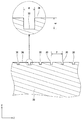
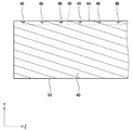
図7は、本発明の他の実施形態に係るタイヤ用モールドのピース40の一部が示された平面図である。図8は、図7のVIII−VIII線に沿った断面図である。このピース40は、突出部42を備えている。この突出部42は、タイヤの溝に相当する。このピース40は、その上面44に多数の第一溝46と1つの第二溝48とを備えている。この上面は、粗面である。第一溝46の一端50は、キャビティ面52に露出している。第一溝46は、モールドの半径方向に延びている。第一溝46の他端54は、第二溝48に至っている。第二溝48は、周方向に延在している。第二溝48は、ピース40の一方の側面56から他方の側面(図示されず)にまで至っている。突出部42を備えないピース40においても、同様の第一溝46及び第二溝48が形成される。このモールドの、溝以外の構成は、図1に示されたモールド2と同等である。
FIG. 7 is a plan view showing a part of a
このモールドが用いられた加硫工程において、ローカバーとキャビティ面52との間のエアーは、第一溝46を通じて第二溝48へと移動する。エアーはさらに、第二溝48を通じて側面56へと排出される。エアーの排出により、ベアーが防止される。ピース40の上面44と、他のピース40の底面58とが密着した場合でも、第一溝46及び第二溝48によりエアーの通路が確保される。
In the vulcanization process using this mold, the air between the raw cover and the
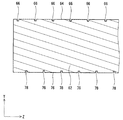
図9は、本発明のさらに他の実施形態に係るタイヤ用モールドのピース62の一部が示された平面図である。図10は、図9のX−X線に沿った断面図である。このピース62は、その上面64に多数の第一溝66を備えている。この上面64は、粗面である。第一溝66の一端68は、キャビティ面70に露出している。第一溝66は、モールドの半径方向に延びている。第一溝66の他端72は、背面74に露出している。このピース62は、その底面76に多数の第二溝78を備えている。この底面76は、粗面である。第二溝78の一端80は、キャビティ面70に露出している。第二溝78は、モールドの半径方向に延びている。第二溝78の他端82は、背面74に露出している。第一溝66と第二溝78とは、周方向において、交互に配置されている。このモールドの、溝以外の構成は、図1に示されたモールド2と同等である。
FIG. 9 is a plan view showing a part of a
このモールドが用いられた加硫工程において、ローカバーとキャビティ面70との間のエアーは、第一溝66及び第二溝78を通じて排出される。エアーの排出により、ベアーが防止される。ピース62の上面64と、他のピース62の底面76とが密着した場合でも、第一溝66及び第二溝78によりエアーの通路が確保される。
In the vulcanization process using this mold, the air between the raw cover and the
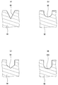
図11(a)から(d)は、それぞれ、本発明のさらに他の実施形態に係るタイヤ用モールドのピースの一部が示された断面図である。図11(a)に示されたピース86は、断面が三角形の溝88を備えている。この溝88により、エアーが排出される。図11(b)に示されたピース90は、断面が実質的に半円の溝92を備えている。この溝92により、エアーが排出される。図11(c)に示されたピース94は、断面が五角形の溝96を備えている。この溝96により、エアーが排出される。図11(d)に示されたピース98は、断面が六角形の溝100を備えている。この溝により、エアーが排出される。
FIGS. 11A to 11D are cross-sectional views each showing a part of a piece of a tire mold according to still another embodiment of the present invention. The piece 86 shown in FIG. 11A includes a
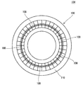
図12は、本発明のさらに他の実施形態に係るタイヤ用モールド104が示された平面図である。このモールド104は、いわゆる「ツーピースモールド」である。このモールド104は、下型106と上型とを備えている。図12には、下型106のみが示されている。上型は、下型106の形状が反転した形状を有する。このモールド104は、多数のブロック108とシェル110とを備えている。ブロック108は、シェル110に固定されている。ブロック108は、円弧状である。多数のブロック108がリング状に配置されている。
FIG. 12 is a plan view showing a
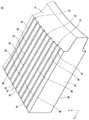
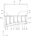
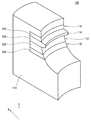
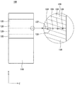
図13は、図12のモールド104のブロック108が示された拡大斜視図である。図14は、図13のブロック108が示された正面図である。このブロック108は、キャビティ面112を備えてる。このキャビティ面112は、突出部114と凹陥部116とを備えている。この突出部114は、タイヤのトレッドの溝に対応する。この突出部114及び凹陥部116により、タイヤにトレッドパターンが形成される。
FIG. 13 is an enlarged perspective view showing the
図13及び14に示されるように、ブロック108はベース118と複数のピース120とからなる。この実施形態では、ブロック108は4枚のピース120を備えている。ピース120の数は、適宜決定される。これらピース120は、軸方向(Y方向)において重ねられている。それぞれのピース120は、板状である。ピース120は、他のピース120と当接している。このピース120は、金属材料からなる。典型的な金属材料は、アルミニウム合金である。
As shown in FIGS. 13 and 14, the
図14に示されるように、ピース120の上面122には多数の溝124が形成されている。この上面122は、粗面である。溝124の一端は、キャビティ面112に露出している。図示されていないが、溝124はモールド104の半径方向(X方向)に延びている。溝124の他端は、ピース120の背面にまで至っている。ピース120の底面126に、溝124が形成されてもよい。
As shown in FIG. 14, a number of
このモールド104が用いられた加硫工程において、ローカバーとキャビティ面112との間のエアーは、溝124を通じて排出される。エアーの排出により、ベアーが防止される。ピース120の上面122と、他のピース120の底面126とが密着した場合でも、溝124によりエアーの通路が確保される。
In the vulcanization process using the
以下、実施例によって本発明の効果が明らかにされるが、この実施例の記載に基づいて本発明が限定的に解釈されるべきではない。 Hereinafter, the effects of the present invention will be clarified by examples. However, the present invention should not be construed in a limited manner based on the description of the examples.
[実施例1]
図1から6に示された形状を有するモールドを用意した。このモールドは、断面が矩形の多数の溝を備えている。この溝は、ピースの上面がレーザービームで切削されることで形成された。溝のピッチPは、10mmである。それぞれの溝において、幅Wは0.05mmであり、深さDは0.05mmである。
[Example 1]
A mold having the shape shown in FIGS. 1 to 6 was prepared. This mold includes a number of grooves having a rectangular cross section. This groove was formed by cutting the upper surface of the piece with a laser beam. The pitch P of the grooves is 10 mm. In each groove, the width W is 0.05 mm and the depth D is 0.05 mm.
[実施例2から6]
下記の表1に示される深さDを備えた溝を形成した他は実施例1と同様にして、実施例2から6のモールドを得た。
[Examples 2 to 6]
Molds of Examples 2 to 6 were obtained in the same manner as in Example 1 except that a groove having a depth D shown in Table 1 below was formed.
[実施例7から10]
下記の表1に示される幅Wを備えた溝を形成した他は実施例1と同様にして、実施例7から10のモールドを得た。
[Examples 7 to 10]
Molds of Examples 7 to 10 were obtained in the same manner as in Example 1 except that a groove having a width W shown in Table 1 below was formed.
[実施例11から14]
ピッチPを下記の表2に示される通りとした他は実施例1と同様にして、実施例11から14のモールドを得た。
[Examples 11 to 14]
Molds of Examples 11 to 14 were obtained in the same manner as Example 1 except that the pitch P was as shown in Table 2 below.
[実施例15から18]
溝の断面形状を下記の表2に示される通りとした他は実施例1と同様にして、実施例15から18のモールドを得た。
[Examples 15 to 18]
Molds of Examples 15 to 18 were obtained in the same manner as Example 1 except that the cross-sectional shape of the grooves was as shown in Table 2 below.
[比較例1]
溝を形成しなかった他は実施例1と同様にして、比較例のモールドを得た。
[Comparative Example 1]
A comparative mold was obtained in the same manner as in Example 1 except that the groove was not formed.
[評価]
モールドにローカバーを投入し、加圧及び加熱して、タイヤを得た。このタイヤを、下記の基準に従って格付けした。
ベアーの程度
A:ベアーが生じていない
B:小さなベアーが生じている
C:大きなベアーが生じている
溝に相当するスピューの程度
A:極めて小さい
B:小さい
C:大きい
この結果が、下記の表1及び2に示されている。
[Evaluation]
A raw cover was put into the mold, and pressurized and heated to obtain a tire. The tire was rated according to the following criteria.
Degree of bear A: No bear is generated B: Small bear is generated C: Large bear is generated Degree of spew corresponding to the groove A: Extremely small B: Small C: Large This result is shown in the following table. 1 and 2.

表1及び2に示されるように、各実施例のモールドでは、ベアーが生じにくい。この評価結果から、本発明の優位性は明らかである。 As shown in Tables 1 and 2, in the molds of the examples, bears are hardly generated. From this evaluation result, the superiority of the present invention is clear.
本発明に係るモールドは、種々のタイヤの製造に適している。 The mold according to the present invention is suitable for manufacturing various tires.
2、104・・・モールド
4・・・セグメント
10・・・ホルダー
12・・・ブロック
14、52、70・・・キャビティ面
16、42・・・突出部
18・・・凹陥部
20、40、62、86、90、94、98、120・・・ピース
30、46、48、66、78、88、92、96、100、124・・・溝
2, 104 ...
Claims (7)
それぞれのピースの内面がキャビティ面を形成しており、
このピースの、他のピースと当接する面が、粗面であるタイヤ用モールド。 It has a number of pieces that are stacked,
The inner surface of each piece forms a cavity surface,
A tire mold in which the surface of this piece that comes into contact with another piece is a rough surface.
並列された多数のピースを備えており、それぞれのピースの内面がキャビティ面を形成しており、このピースの他のピースと当接する面が粗面であるモールドに、上記ローカバーが投入される工程
及び
このローカバーがモールド内で加圧及び加熱される工程
を含むタイヤ製造方法。 A process for obtaining a raw cover by preforming,
A step of putting the raw cover into a mold having a plurality of pieces arranged in parallel, the inner surface of each piece forming a cavity surface, and the surface that comes into contact with the other piece of this piece is a rough surface And the tire manufacturing method including the process by which this raw cover is pressurized and heated within a mold.
Priority Applications (2)
| Application Number | Priority Date | Filing Date | Title |
|---|---|---|---|
| JP2008323144A JP2010143086A (en) | 2008-12-19 | 2008-12-19 | Mold for tire |
| CN200910209347A CN101746000A (en) | 2008-12-19 | 2009-11-04 | Mold for tire |
Applications Claiming Priority (1)
| Application Number | Priority Date | Filing Date | Title |
|---|---|---|---|
| JP2008323144A JP2010143086A (en) | 2008-12-19 | 2008-12-19 | Mold for tire |
Publications (1)
| Publication Number | Publication Date |
|---|---|
| JP2010143086A true JP2010143086A (en) | 2010-07-01 |
Family
ID=42473926
Family Applications (1)
| Application Number | Title | Priority Date | Filing Date |
|---|---|---|---|
| JP2008323144A Pending JP2010143086A (en) | 2008-12-19 | 2008-12-19 | Mold for tire |
Country Status (2)
| Country | Link |
|---|---|
| JP (1) | JP2010143086A (en) |
| CN (1) | CN101746000A (en) |
Cited By (2)
| Publication number | Priority date | Publication date | Assignee | Title |
|---|---|---|---|---|
| JP2012176517A (en) * | 2011-02-25 | 2012-09-13 | Yokohama Rubber Co Ltd:The | Tire vulcanization mold |
| CN106738497A (en) * | 2017-03-14 | 2017-05-31 | 青岛金科模具有限公司 | Pattern block and tire-mold |
Families Citing this family (1)
| Publication number | Priority date | Publication date | Assignee | Title |
|---|---|---|---|---|
| JP2020142459A (en) * | 2019-03-07 | 2020-09-10 | 住友ゴム工業株式会社 | Tire vulcanization mold |
Citations (3)
| Publication number | Priority date | Publication date | Assignee | Title |
|---|---|---|---|---|
| JPH02295706A (en) * | 1989-05-10 | 1990-12-06 | Yokohama Rubber Co Ltd:The | Sectional type tire mold and preparation thereof |
| JPH06226744A (en) * | 1993-02-03 | 1994-08-16 | Hoden Seimitsu Kako Kenkyusho Ltd | Tire forming mold having exhaust groove and method of manufacturing the same |
| JPH1071617A (en) * | 1996-08-29 | 1998-03-17 | Bridgestone Corp | Tire vulcanizing method and tire vulcanizing mold using the same |
Family Cites Families (2)
| Publication number | Priority date | Publication date | Assignee | Title |
|---|---|---|---|---|
| DE102004052766A1 (en) * | 2004-10-30 | 2006-05-04 | Continental Aktiengesellschaft | Tire vulcanizing mold with a plurality of profile segments which can be joined together to form a circumferentially closed mold |
| CN100566969C (en) * | 2007-04-05 | 2009-12-09 | 鸣庆企业股份有限公司 | Matrix assembly device for forming die |
-
2008
- 2008-12-19 JP JP2008323144A patent/JP2010143086A/en active Pending
-
2009
- 2009-11-04 CN CN200910209347A patent/CN101746000A/en active Pending
Patent Citations (3)
| Publication number | Priority date | Publication date | Assignee | Title |
|---|---|---|---|---|
| JPH02295706A (en) * | 1989-05-10 | 1990-12-06 | Yokohama Rubber Co Ltd:The | Sectional type tire mold and preparation thereof |
| JPH06226744A (en) * | 1993-02-03 | 1994-08-16 | Hoden Seimitsu Kako Kenkyusho Ltd | Tire forming mold having exhaust groove and method of manufacturing the same |
| JPH1071617A (en) * | 1996-08-29 | 1998-03-17 | Bridgestone Corp | Tire vulcanizing method and tire vulcanizing mold using the same |
Cited By (2)
| Publication number | Priority date | Publication date | Assignee | Title |
|---|---|---|---|---|
| JP2012176517A (en) * | 2011-02-25 | 2012-09-13 | Yokohama Rubber Co Ltd:The | Tire vulcanization mold |
| CN106738497A (en) * | 2017-03-14 | 2017-05-31 | 青岛金科模具有限公司 | Pattern block and tire-mold |
Also Published As
| Publication number | Publication date |
|---|---|
| CN101746000A (en) | 2010-06-23 |
Similar Documents
| Publication | Publication Date | Title |
|---|---|---|
| JP4676509B2 (en) | Mold for tire | |
| JP5265148B2 (en) | Manufacturing method of tire mold | |
| JP5265504B2 (en) | Mold for tire | |
| JP4690382B2 (en) | Manufacturing method of tire mold | |
| US10870248B2 (en) | Non-symmetrical tread ring parting line mold | |
| JP5254198B2 (en) | Mold for tire | |
| EP0384775B1 (en) | Split dies for casting small segments of tire mold | |
| JP2010143086A (en) | Mold for tire | |
| JP2010046902A (en) | Method of manufacturing tire vulcanizing mold | |
| JP4236527B2 (en) | Tire molding die and tire molded using the tire molding die | |
| JP2016147459A (en) | Mold for tire | |
| JP4847167B2 (en) | Manufacturing method of tire mold | |
| JP2007144997A (en) | Manufacturing method of tire mold | |
| JP6199166B2 (en) | Tire vulcanization mold and tire manufacturing method | |
| JP7768758B2 (en) | Tire manufacturing mold | |
| JP2018030279A (en) | Mold for tire | |
| JP4346466B2 (en) | Manufacturing method of tire vulcanizing mold | |
| JP2008188883A (en) | Mold for vulcanization-molding tire | |
| JP4926656B2 (en) | Mold for tire | |
| JP4052386B2 (en) | Tire mold and method of manufacturing pneumatic tire using the same | |
| JP7468222B2 (en) | mold | |
| JP7768759B2 (en) | Tire manufacturing mold | |
| CN114083724B (en) | Methods for manufacturing tire molds and methods for manufacturing tires. | |
| JP4946369B2 (en) | Exhaust plug used for vent holes in tire vulcanization molds | |
| JP6008732B2 (en) | Tire vulcanizing mold |
Legal Events
| Date | Code | Title | Description |
|---|---|---|---|
| A621 | Written request for application examination |
Free format text: JAPANESE INTERMEDIATE CODE: A621 Effective date: 20100416 |
|
| A977 | Report on retrieval |
Free format text: JAPANESE INTERMEDIATE CODE: A971007 Effective date: 20101112 |
|
| A131 | Notification of reasons for refusal |
Effective date: 20101130 Free format text: JAPANESE INTERMEDIATE CODE: A131 |
|
| A521 | Written amendment |
Effective date: 20110126 Free format text: JAPANESE INTERMEDIATE CODE: A523 |
|
| A02 | Decision of refusal |
Free format text: JAPANESE INTERMEDIATE CODE: A02 Effective date: 20110301 |