JP2010142890A - Method of correcting outer circumferential shape of cutting member, dresser board, and cutting device - Google Patents
Method of correcting outer circumferential shape of cutting member, dresser board, and cutting device Download PDFInfo
- Publication number
- JP2010142890A JP2010142890A JP2008321230A JP2008321230A JP2010142890A JP 2010142890 A JP2010142890 A JP 2010142890A JP 2008321230 A JP2008321230 A JP 2008321230A JP 2008321230 A JP2008321230 A JP 2008321230A JP 2010142890 A JP2010142890 A JP 2010142890A
- Authority
- JP
- Japan
- Prior art keywords
- cutting
- blade
- cutting member
- dresser board
- outer peripheral
- Prior art date
- Legal status (The legal status is an assumption and is not a legal conclusion. Google has not performed a legal analysis and makes no representation as to the accuracy of the status listed.)
- Pending
Links
Images


Landscapes
- Grinding-Machine Dressing And Accessory Apparatuses (AREA)
Abstract
Description
本発明は、切削部材の外周形状の修正方法、ドレッサーボード及び切削装置に関する。 The present invention relates to a method for correcting the outer peripheral shape of a cutting member, a dresser board, and a cutting apparatus.
機器間や機器内など比較的近距離の信号伝送を光によって行う光インターコネクションでは、面発光型レーザ(VCSEL)やフォトダイオードなどの実装面に垂直な方向に光が入出射する面型の受発光素子と実装基板面に平行な光伝送路との光結合技術が必須である。光素子の受発光面と光伝送路を光結合をコンパクトに実現する有力な手段としては、光伝送路に形成した45度傾斜面の反射により光の伝播方向を90度変更する方法が挙げられる。 In optical interconnection that uses light to transmit signals at relatively short distances, such as between devices and within devices, a surface-type receiving device in which light enters and exits in a direction perpendicular to the mounting surface of a surface emitting laser (VCSEL) or a photodiode. An optical coupling technique between the light emitting element and the optical transmission path parallel to the mounting substrate surface is essential. As an effective means for realizing a compact optical coupling between the light receiving / emitting surface of the optical element and the optical transmission path, there is a method of changing the light propagation direction by 90 degrees by reflection of a 45-degree inclined surface formed in the optical transmission path. .
光伝送路に45度傾斜面を形成する方法として、例えば特許文献1に開示されたものがある。 As a method for forming a 45-degree inclined surface in an optical transmission line, for example, there is one disclosed in Patent Document 1.
特許文献1に開示された方法は、刃先の少なくとも片側に傾斜面を有するダイヤモンドブレード(切削部材)を光導波路に対して垂直に当ててダイシングソーを用いた切削加工を行うことにより、光導波路に光路変換面として45度傾斜面を形成するものである。ダイヤモンドブレードに含まれる砥粒の平均粒径を1〜5μmとすることにより、光路変換面における反射率の高い光導波路を作製することができる。 In the method disclosed in Patent Document 1, a diamond blade (cutting member) having an inclined surface on at least one side of a cutting edge is applied perpendicularly to the optical waveguide to perform a cutting process using a dicing saw. A 45-degree inclined surface is formed as the optical path conversion surface. By setting the average grain size of the abrasive grains contained in the diamond blade to 1 to 5 μm, an optical waveguide having a high reflectance on the optical path conversion surface can be produced.
ダイシング装置(切削装置)に取り付けた状態でブレードの形状を成形する方法として、例えば特許文献2に開示されたものがある。 As a method of forming the shape of the blade while attached to a dicing device (cutting device), for example, there is one disclosed in Patent Document 2.
特許文献2に開示された方法は、ダイシング装置に取り付けられたブレードを回転させながら放電によって成形するものである。 The method disclosed in Patent Document 2 is formed by electric discharge while rotating a blade attached to a dicing apparatus.
本発明の目的は、外周部に傾斜面を有する切削部材の偏芯量及び傾斜面の崩れを修正することができる切削部材の外周形状の修正方法、ドレッサーボード及び切削装置を提供することにある。 An object of the present invention is to provide a method for correcting the outer peripheral shape of a cutting member, a dresser board, and a cutting device that can correct the eccentric amount of the cutting member having an inclined surface on the outer peripheral portion and the collapse of the inclined surface. .
本発明の一態様は、上記目的を達成するため、以下の切削部材の外周形状の修正方法、ドレッサーボード及び切削装置を提供する。 In order to achieve the above object, one aspect of the present invention provides the following method for correcting the outer peripheral shape of a cutting member, a dresser board, and a cutting apparatus.
[1]外周部に傾斜面を有する円形の切削部材を切削装置の回転軸に取り付け、被切削物が配置される台上にドレッサーボードを配置する工程と、前記切削部材で前記ドレッサーボードの同一箇所を切り込み深さを大きくしながら繰り返し切削する工程と、を含む切削部材の外周形状の修正方法。 [1] A step of attaching a circular cutting member having an inclined surface on the outer peripheral portion to a rotating shaft of a cutting apparatus and arranging a dresser board on a table on which a workpiece is arranged, and the same cutting member with the cutting member. And a step of repeatedly cutting the portion while increasing the depth of cut, and a method for correcting the outer peripheral shape of the cutting member.
[2]外周部に傾斜面を有する円形の切削部材を切削装置の回転軸に取り付け、被切削物が配置される台上に、前記切削部材の外周部の形状に対応した複数の溝が形成されたドレッサーボードを配置する工程と、前記切削部材で前記ドレッサーボードの前記複数の溝を順次切削する工程と、を含む切削部材の外周形状の修正方法。 [2] A circular cutting member having an inclined surface on the outer peripheral portion is attached to the rotating shaft of the cutting device, and a plurality of grooves corresponding to the shape of the outer peripheral portion of the cutting member are formed on a table on which the workpiece is placed. A method of correcting the outer peripheral shape of the cutting member, comprising: arranging the dresser board that has been arranged; and sequentially cutting the plurality of grooves of the dresser board with the cutting member.
[3]前記溝部の溝幅は、前記切削部材の幅よりも大きい前記[2]に記載の切削部材の外周形状の修正方法。 [3] The method for correcting the outer peripheral shape of the cutting member according to [2], wherein the groove width of the groove portion is larger than the width of the cutting member.
[4]1つの面に直線状に形成された複数の溝部を有し、前記溝部を構成する少なくとも1つの面が、前記1つの面に対して傾斜しているドレッサーボード。 [4] A dresser board having a plurality of grooves formed linearly on one surface, and at least one surface constituting the groove is inclined with respect to the one surface.
[5]前記溝部は、溝底に凹状の逃げ部が形成された前記[4]に記載のドレッサーボード。 [5] The dresser board according to [4], wherein the groove portion has a concave relief portion formed at a groove bottom.
[6]円形の切削部材が取り付けられる回転軸と、被切削物又はドレッサーボードが配置される台と、前記回転軸及び前記台を相対的に移動させる移動手段と、前記切削部材で前記台上に配置された前記ドレッサーボードの同一箇所を切り込み深さを大きくしながら繰り返し切削するように前記移動手段を制御する制御手段と、を備えた切削装置。 [6] A rotating shaft to which a circular cutting member is attached, a table on which a workpiece or a dresser board is disposed, a moving means for relatively moving the rotating shaft and the table, and the cutting member on the table And a control means for controlling the moving means so as to repeatedly cut the same portion of the dresser board arranged at a depth while increasing the cutting depth.
請求項1に記載の発明によれば、外周部に傾斜面を有する切削部材の偏芯量及び傾斜面の崩れを修正することができる。 According to the first aspect of the present invention, it is possible to correct the eccentricity of the cutting member having the inclined surface on the outer peripheral portion and the collapse of the inclined surface.
請求項2に記載の発明によれば、外周部に傾斜面を有する切削部材の偏芯量及び傾斜面の崩れを修正することができる。 According to the second aspect of the present invention, it is possible to correct the eccentricity of the cutting member having the inclined surface on the outer peripheral portion and the collapse of the inclined surface.
請求項3に記載の発明によれば、傾斜面全体の形状を修正することができる。 According to invention of Claim 3, the shape of the whole inclined surface can be corrected.
請求項4に記載の発明によれば、外周部に傾斜面を有する切削部材の偏芯量及び傾斜面の崩れを修正することができるドレッサーボードを提供できる。 According to invention of Claim 4, the dresser board which can correct | amend the eccentric amount of the cutting member which has an inclined surface in an outer peripheral part, and collapse of an inclined surface can be provided.
請求項5に記載の発明によれば、傾斜面の先端が丸くなるのを防ぐことができる。 According to invention of Claim 5, it can prevent that the front-end | tip of an inclined surface becomes round.
請求項6に記載の発明によれば、切削装置に設けられた外周部に傾斜面を有する切削部材の偏芯量及び傾斜面の崩れを修正できる切削装置を提供できる。 According to invention of Claim 6, the cutting device which can correct | amend the eccentric amount of the cutting member which has an inclined surface in the outer peripheral part provided in the cutting device, and collapse of an inclined surface can be provided.
[第1の実施の形態]
図1は、本発明の第1の実施の形態に係るダイシング装置の概略の構成を示す図である。なお、同図中のX,Y,Zは、互いに直交する方向を示す。
[First Embodiment]
FIG. 1 is a diagram showing a schematic configuration of a dicing apparatus according to a first embodiment of the present invention. In the figure, X, Y, and Z indicate directions orthogonal to each other.
この切削装置としてのダイシング装置100は、高速回転する回転軸101と、回転軸101に円形の切削部材としてのブレード10Aを固定するブレード固定ジグ102と、加工物103を真空吸着により保持するとともにY方向に移動可能なY方向移動テーブル104とを備える。Y方向移動テーブル104は、被切削物としての加工物103又はドレッサーボードが配置される台を構成する。
A dicing apparatus 100 as a cutting apparatus includes a rotary shaft 101 that rotates at a high speed, a
また、ダイシング装置100は、回転軸101を回転駆動する回転駆動部110と、回転軸101及び回転駆動部110をX方向及びZ方向に移動可能なX、Z方向移動機構111と、X、Z方向移動機構111を駆動する移動機構駆動部112と、Y方向移動テーブル104を駆動するテーブル駆動部113と、回転駆動部110、移動機構駆動部112及びテーブル駆動部113を制御する制御手段としての制御部114と、制御部114に接続された記憶部115とを備える。X、Z方向移動機構111、移動機構駆動部112及びテーブル駆動部113は、回転軸101及びY方向移動テーブル104を相対的に移動させる移動手段を構成する。
Further, the dicing apparatus 100 includes a
ここで、本明細書において、ブレード(切削部材)のドレッシングとは、切削性能を回復させるための目立てと、外周部の真円出しの両方を含むものとする。ドレッサーボードは、ブレードのドレッシングに用いられるものをいうものとする。 Here, in the present specification, the dressing of the blade (cutting member) includes both sharpening for restoring the cutting performance and rounding of the outer peripheral portion. The dresser board shall be used for dressing a blade.
制御部114は、CPU等を有して構成され、記憶部115は、ROM、RAM、HDD等を有して構成されている。記憶部115には、ブレード10Aの外周形状を修正するための修正プログラム116aと、加工物103に溝部を形成した後、加工物103を切断するための制御プログラム116bが格納されている。
The
ダイヤモンドブレード10Aは、互いに平行な側面10a,10bに対して45度傾斜した傾斜面11を外周に有する。ブレード10Aは、例えば粒度#3000〜#6000の細かいダイヤモンド砥粒を用いたダイヤモンドブレードを用いることができるが、これに限定されない。
The
ダイヤモンドブレードは、例えば、アルミニウム等の金属からなる厚さ0.1〜0.2mm程度で外径が50mm程度の円形基板の外周部に傾斜面11を形成し、傾斜面11を含む外周部の表面にダイヤモンド砥粒を電着して形成することができる。円形基板の中央部には、回転軸101に取り付けるための取り付け穴が形成されている。ダイヤモンド砥粒の電着には、電気メッキ法を用いることができる。また、ダイヤモンドブレードは、例えば、中央に円形の開口を有する円形電極上にダイヤモンド砥粒を内包させながらニッケルメッキ層を成長させ、ニッケルメッキ層の厚さが0.1〜0.3mmとなった後に円形電極から剥離して形成してもよい。このとき傾斜面11は、斜面形成用装置の回転軸に固定されて回転するブレードの外周部に所望の角度から斜面形成用の砥石を押し当て、研削することで形成される。また、ダイヤモンドブレードは、例えば、ダイヤモンド砥粒をレジン等で固めて焼結して形成してもよい。
The diamond blade, for example, forms an
図2(a)は、ブレードの外周形状の修正前の状態を示す図、図2(b)は、図2(a)の傾斜面の詳細を示す図である。図2(a)に示すように、ブレード10Aをブレード固定ジグ102により回転軸101に取り付けた場合、一般に、回転軸101の中心線101aとブレード10Aの中心線10cとのズレ量、すなわち偏芯量eが10〜20μm程度存在する。
FIG. 2A is a diagram showing a state before correction of the outer peripheral shape of the blade, and FIG. 2B is a diagram showing details of the inclined surface of FIG. 2A. As shown in FIG. 2A, when the
図2(a)に示すように、偏芯量eが大きいブレード10Aを用いて溝加工を行うと、傾斜面11の一部のみが切削に寄与する片当りの状態となり、短距離の切削でブレードの目詰まりが生じ、加工品質が低下するおそれがある。また、図2(b)に示すように、理想的な傾斜面11の斜面形状11aに対し、傾斜面11の一部に斜面形状の崩れ11bが存在する場合、被切削物には斜面形状の崩れ11bを反映した加工面が形成され、加工品質が低下するおそれがある。
As shown in FIG. 2A, when grooving is performed using a
(比較例)
図3は、比較例に係るブレードのドレッシング方法を説明するための図であり、(a)は斜視図、(b)は断面図である。
(Comparative example)
3A and 3B are diagrams for explaining a blade dressing method according to a comparative example, in which FIG. 3A is a perspective view and FIG. 3B is a cross-sectional view.
ウェハの切断等に使用される外周形状が矩形のブレードの場合は、ドレッシングによってブレードの偏芯を修正することができる。ドレッシング作業は、一般的に、ブレードでドレッサーボードを切削して溝を形成し、切削位置を変えながらドレッサーボード上に複数の溝を形成することで行われる。 When the outer peripheral shape used for cutting the wafer is a rectangular blade, the eccentricity of the blade can be corrected by dressing. The dressing operation is generally performed by cutting the dresser board with a blade to form grooves, and forming a plurality of grooves on the dresser board while changing the cutting position.
このドレッシング作業を外周部に傾斜面11を有するブレード10Aに適用した場合、図3(a)に示すように、ドレッサーボード20に複数の切削溝22を形成すると、図3(b)に示すように、切削溝22の数が多い程、ブレード10Aの磨耗量が多くなり、ブレード10Aの外周部の先端11cは徐々に丸みを帯びるため、平坦な傾斜面11を形成するには適さない。
When this dressing operation is applied to the
ドレッサーボード20は、例えば、粒度#1000〜#4000のグリーンカーボランダムやホワイトアランダム等の研磨材をレジン等で固めて焼結したものを用いることができるが、これに限定されない。
The
図4は、本実施の形態のブレードの外周形状の修正方法を説明するための図であり、(a)は斜視図、(b)は断面図である。 4A and 4B are diagrams for explaining a method for correcting the outer peripheral shape of the blade according to the present embodiment, wherein FIG. 4A is a perspective view and FIG. 4B is a cross-sectional view.
本実施の形態に係るブレード10Aの外周形状の修正方法は、ブレード10Aを本ダイシング装置1の回転軸101に取り付けた後、ブレード10Aで切り込み深さDを大きくしながらドレッサーボード20の同一箇所を繰り返し切削することで行われる。この修正方法は、本ダイシング装置100に適用して実現することができる。
In the method of correcting the outer peripheral shape of the
すなわち、初回切り込み深さDと、1切削毎の切り込み深さΔD及び切削繰り返し回数N(同図では3回)を設定した修正プログラム116aをダイシング装置1の記憶部115に書き込む。
That is, the
制御部114は、修正プログラム116aに従い、回転駆動部110、移動機構駆動部112及びテーブル駆動部113を制御し、ブレード10Aを回転軸101に固定した状態で、切り込み深さDを大きくしながらドレッサーボード20の同一箇所を繰り返し切削し、ブレード10Aの外周形状を修正する。
The
本実施の形態に係るブレード10Aの外周形状の修正方法によれば、少なくとも2回目以降の切削ではブレード10Aの傾斜面11全体が同様の切削量と均一な磨耗が発生し、ブレード10Aの偏芯と斜面形状の崩れ11bを修正することができる。なお、ドレッサーボード20に予め1つの修正用溝21Aを形成しておき、この修正用溝21Aに対してブレード10Aで繰り返し切削を行ってもよい。
According to the method for correcting the outer peripheral shape of the
[第2の実施の形態]
図5は、本発明の第2の実施の形態に係るドレッサーボードの要部を示す断面図である。このドレッサーボード20は、ブレード10Aの理想的な外周形状に対応した複数(同図では4つ)の修正用溝21Aを有している。これらの修正用溝21Aは、ピッチPで形成され、深さD及び溝幅Wが互いに等しく、溝幅Wは、ブレード10Aの厚みTよりも50〜200μm大きく形成されている。修正用溝21Aは、上面20aに対して45度傾斜した傾斜面21aと、上面20aに対して垂直な垂直面21bとから構成されている。
[Second Embodiment]
FIG. 5 is a cross-sectional view showing the main part of the dresser board according to the second embodiment of the present invention. The
本実施の形態のドレッサーボード20は、例えば、粒度#1000〜#4000のグリーンカーボランダムやホワイトアランダム等の研磨材をレジン等で固めて焼結したものを用いることができるが、矩形状のボードを形成した後、上面20aにブレードで切削して複数の修正用溝21Aを形成してもよい。
As the
本実施の形態に係るブレード10Aの外周形状の修正方法は、ドレッサーボード20に形成された修正用溝21Aをブレード10Aで僅か切削し、順次他の修正用溝21Aに対しても同様に切削することで行われる。この修正方法は、本ダイシング装置100に適用して実現することができる。
In the method for correcting the outer peripheral shape of the
すなわち、ブレード10Aでドレッサーボード20の上面20aからの切削深さDと、ブレード10Aの移動ピッチP(修正用溝21Aのピッチと等しい。)と、切削回数Nとを設定した修正プログラム116aをダイシング装置1の記憶部115に書き込む。
That is, the cutting program D in which the cutting depth D from the
制御部114は、修正プログラム116aに従い、回転駆動部110、移動機構駆動部112及びテーブル駆動部113を制御し、ブレード10Aを回転軸101に固定した状態で、ドレッサーボード20の複数の箇所に形成された修正用溝21Aを順次切削し、ブレード10Aの外周形状を修正する。
The
本実施の形態に係るブレード10Aの外周形状の修正方法によれば、ダイシング装置のアライメント精度の範囲内でブレード10Aの傾斜面11のみを研磨することができる。
According to the method for correcting the outer peripheral shape of the
なお、修正用溝21Aに対する切削は、前述の第1の実施の形態と同様に切り込み深さを大きくしながら同一溝を複数回切削してもよい。また、修正用溝21Aの溝幅Wは、ブレード10Aの厚さTと等しいか、又は厚さTよりも小さくてもよい。この場合は、ブレード10Aの側面10a,10bも研磨される場合もあるが、ブレード10Aの偏芯と斜面形状の崩れ11bを修正することができる。
In addition, the cutting with respect to the
[第3の実施の形態]
図6は、本発明の第3の実施の形態に係るドレッサーボードの要部を示す断面図である。このドレッサーボード20は、図5に示すドレッサーボード20の修正用溝21Aの溝底に凹状の先端逃げ部21cを付加したものである。
[Third Embodiment]
FIG. 6 is a cross-sectional view showing the main part of the dresser board according to the third embodiment of the present invention. This
ブレード10Aの傾斜面11の先端11cは、ドレッシングによって丸みを帯びる傾向にあるが、先端逃げ部21cによってそれを回避することが可能になる。ブレード10Aの傾斜面11の先端11c側に研磨されない領域が形成されるが、後述する光導波路に反射面を形成する上で支障はない。
The
本実施の形態に係るブレード10Aの外周形状の修正方法は、第2の実施の形態と同様に、本ダイシング装置100に適用して実現することができる。
The method for correcting the outer peripheral shape of the
[第4の実施の形態]
図7は、本発明の第4の実施の形態に係るブレード及びドレーサーボードの要部を示す断面図である。
[Fourth Embodiment]
FIG. 7 is a cross-sectional view showing the main parts of a blade and a dresser board according to the fourth embodiment of the present invention.
この切削部材としてのブレード10Bは、互いに平行な側面10a,10bに対して45度傾斜したV字状の一対の傾斜面11を外周に有する。
The blade 10B as the cutting member has a pair of V-shaped
ドレッサーボード20は、ブレード10Bの理想的な外周形状に対応した複数(同図では3つ)の修正用溝21Bを有している。これらの修正用溝21Bは、ピッチPで形成され、深さD及び溝幅Wが互いに等しく、溝幅Wは、ブレード10Bの厚みTよりも50〜200μm大きく形成されている。修正用溝21Bは、上面20aに対して45度傾斜したV字状の一対の傾斜面21aから構成されている。
The
本実施の形態に係るブレード10Bの外周形状の修正方法は、第2の実施の形態と同様に、本ダイシング装置100に適用して実現することができる。 The method for correcting the outer peripheral shape of the blade 10B according to the present embodiment can be realized by being applied to the dicing apparatus 100, as in the second embodiment.
[第5の実施の形態]
図8は、本発明の第5の実施の形態に係るドレーサーボードを示す断面図である。このドレッサーボード20は、図7に示すドレッサーボード20の修正用溝21Bの溝底に凹状の先端逃げ部21cを付加したものである。
[Fifth Embodiment]
FIG. 8 is a sectional view showing a dresser board according to the fifth embodiment of the present invention. This
ブレード10Bの傾斜面11の先端11cは、ドレッシングによって丸みを帯びる傾向にあるが、先端逃げ部21cによってそれを回避することが可能になる。ブレード10Bの傾斜面11の先端11c側に研磨されない領域が形成されるが、後述する光導波路に反射面を形成する上で支障はない。
The
本実施の形態に係るブレード10Bの外周形状の修正方法は、第2の実施の形態と同様に、本ダイシング装置100に適用して実現することができる。 The method for correcting the outer peripheral shape of the blade 10B according to the present embodiment can be realized by being applied to the dicing apparatus 100, as in the second embodiment.
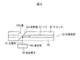
図9は、第1、第2又は第3の実施の形態に係るブレードによって形成された反射面を有する光導波路の一例を示す断面図である。 FIG. 9 is a cross-sectional view showing an example of an optical waveguide having a reflective surface formed by a blade according to the first, second, or third embodiment.
この光導波路50は、例えば、エポキシ樹脂フィルムから形成され、コア51と、コア51の周囲に設けられ、コア51の屈折率よりも小さい屈折率の材料から形成されたクラッド52とを備え、第1乃至第3の実施の形態に係るブレード10Aによる切削によって反射面53aを有する溝53Aが形成されている。面発光型レーザ等の発光素子60の発光部60aから出射された光信号61は、反射面53aで反射された後、コア51を伝播する。なお、光導波路50の他端側にも同様の反射面をブレード10Aで形成することにより、コア51の他端に伝播した光信号61は、光導波路50の他端側に形成された反射面で反射してフォトダイオード等の受光素子に受光される。
The optical waveguide 50 is formed of, for example, an epoxy resin film, and includes a core 51 and a clad 52 provided around the core 51 and formed of a material having a refractive index smaller than that of the core 51. A groove 53A having a reflective surface 53a is formed by cutting with the
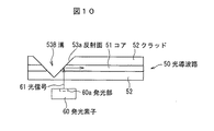
図10は、第4又は第5の実施の形態に係るブレードによって形成された反射面を有する光導波路の一例を示す断面図である。 FIG. 10 is a cross-sectional view showing an example of an optical waveguide having a reflecting surface formed by a blade according to the fourth or fifth embodiment.
この光導波路50は、例えば、エポキシ樹脂フィルムから形成され、コア51と、コア51の周囲に設けられ、コア51の屈折率よりも小さい屈折率の材料から形成されたクラッド52とを備え、第4又は第5の実施の形態に係る、傾斜面11を有するブレード10Bによる切削によって反射面53aを有するV字状の溝53Bが形成されている。面発光型レーザ等の発光素子60の発光部60aから出射された光信号61は、反射面53aで反射された後、コア51を伝播する。なお、光導波路50の他端側にも同様の反射面をブレード10Bで形成することにより、コア51の他端に伝播した光信号61は、光導波路50の他端側に形成された反射面で反射してフォトダイオード等の受光素子に受光される。
The optical waveguide 50 is formed of, for example, an epoxy resin film, and includes a core 51 and a clad 52 provided around the core 51 and formed of a material having a refractive index smaller than that of the core 51. A V-shaped groove 53B having a reflective surface 53a is formed by cutting with a blade 10B having an
次に、本発明の実施例1について説明する。 Next, Example 1 of the present invention will be described.
ブレード10Aとして、外周部に45度の傾斜面11を有し、粒度#5000、厚さ0.15mmのダイヤモンドブレードを用意し、傾斜面11のSEM観察を行ったところ、傾斜面11の一部に斜面形状の崩れ11bが確認された。
As the
次に、上記ブレード10Aをダイシング装置100の回転軸101に固定した。ブレード10Aの中心線10cの回転軸101の中心線101aからの偏芯量eを、8倍のマクロレンズを介してCCDカメラ画像処理装置により測定したところ、10μmであった。
Next, the blade 10 </ b> A was fixed to the rotating shaft 101 of the dicing apparatus 100. The amount of eccentricity e of the center line 10c of the
次に、ダイシング装置100のY方向移動テーブル104上に、加工物103として光導波路の材料である厚さ200μmのエポキシ樹脂フィルムを設置し、ブレード回転数30000rpm、切削速度5mm/secの条件でエポキシ樹脂フィルムを切削した。 Next, on the Y-direction moving table 104 of the dicing apparatus 100, an epoxy resin film having a thickness of 200 μm, which is a material of the optical waveguide, is set as the workpiece 103, and the epoxy is used under the conditions of blade rotation speed of 30000 rpm and cutting speed of 5 mm / sec. The resin film was cut.
切削により形成されたエポキシ樹脂フィルムの45度傾斜面の面粗さを共焦点顕微鏡で測定したところ、面粗さ(Ra)120nmであった。 When the surface roughness of the 45-degree inclined surface of the epoxy resin film formed by cutting was measured with a confocal microscope, the surface roughness (Ra) was 120 nm.
次に、複数の修正用溝21Aを形成した粒度#3000のドレッサーボード20をダイシング装置100のY方向移動テーブル104に設置した。
Next, the
ドレッサーボード20は、粒度#1200、厚さ0.3mmのブレードを用いて上面20aから0.28mm切り込むことにより45度の傾斜面21Aを形成した。
The
次に、上記ドレッサーボード20の修正用溝21Aに対してアライメントを取り、初回切り込み深さDをドレッサーボード20の上面20aから0.3mmとし、1切削毎の切り込み深さΔDを20μm、切削繰り返し回数Nを10回とし、5mm/secの切削速度で同一の溝を繰り返し切削した。
Next, the
上記工程の後に測定したブレードの回転軸101に対する偏芯量eは、1μm以下であった。 The amount of eccentricity e of the blade measured with respect to the rotating shaft 101 after the above process was 1 μm or less.
次に、ダイシング装置100のY方向移動テーブル104に厚さ200μmのエポキシ樹脂フィルムを設置し、ブレード回転数30000rpm、切削速度5mm/secの条件でエポキシ樹脂フィルムを切削した。切削により形成されたエポキシ樹脂フィルムの45度傾斜面の面粗さを共焦点顕微鏡で測定したところ、面粗さ(Ra)30nmであり、光学ミラー面として充分な平滑面が得られた。 Next, an epoxy resin film having a thickness of 200 μm was placed on the Y-direction moving table 104 of the dicing apparatus 100, and the epoxy resin film was cut under the conditions of a blade rotation speed of 30000 rpm and a cutting speed of 5 mm / sec. When the surface roughness of the 45-degree inclined surface of the epoxy resin film formed by cutting was measured with a confocal microscope, the surface roughness (Ra) was 30 nm, and a smooth surface sufficient as an optical mirror surface was obtained.
次に、ブレード10Aをダイシング装置から取り外し、傾斜面11のSEM観察を行ったところ、回転軸101に取り付け前に確認された斜面形状の崩れ11bは消失しており、良好な傾斜面11となっていることが確認された。
Next, when the
[他の実施の形態]
なお、本発明は、上記実施の形態及び実施例に限定されず、その要旨を変更しない範囲内で種々な変形が可能である。
[Other embodiments]
In addition, this invention is not limited to the said embodiment and Example, A various deformation | transformation is possible within the range which does not change the summary.
1…ダイシング装置、10A,10B…ブレード、10a,10b…側面、10c…中心線、11…傾斜面、11a…斜面形状、11b…斜面形状の崩れ、11c…先端、20…ドレッサーボード、20a…上面、21A,21B…修正用溝、21a…傾斜面、21b…垂直面、21c…先端逃げ部、22…切削溝、50…光導波路、51…コア、52…クラッド、53A,53B…溝、53a…反射面、60…発光素子、60a…発光部、61…光信号、100…ダイシング装置、101a…回転軸の中心線、101…回転軸、102…ブレード固定ジグ、103…加工物、104…方向移動テーブル、110…回転駆動部、111…X、Z方向移動機構、112…移動機構駆動部、113…テーブル駆動部、114…制御部、115…記憶部、116a…修正プログラム、116b…制御プログラム、D…切り込み深さ、ΔD…切削毎の切り込み深さ、e…偏芯量、P…ピッチ、W…溝幅 DESCRIPTION OF SYMBOLS 1 ... Dicing apparatus, 10A, 10B ... Blade, 10a, 10b ... Side surface, 10c ... Center line, 11 ... Inclined surface, 11a ... Slope shape, 11b ... Slope shape collapse, 11c ... Tip, 20 ... Dresser board, 20a ... Upper surface, 21A, 21B ... correction groove, 21a ... inclined surface, 21b ... vertical surface, 21c ... tip relief, 22 ... cutting groove, 50 ... optical waveguide, 51 ... core, 52 ... cladding, 53A, 53B ... groove, 53a ... reflecting surface, 60 ... light emitting element, 60a ... light emitting section, 61 ... light signal, 100 ... dicing device, 101a ... centerline of rotating shaft, 101 ... rotating shaft, 102 ... blade fixing jig, 103 ... workpiece, 104 ... direction moving table, 110 ... rotation driving unit, 111 ... X, Z direction moving mechanism, 112 ... moving mechanism driving unit, 113 ... table driving unit, 114 ... control unit, 115 ... Parts, 116a ... fix, 116 b ... control program, D ... depth of cut, [Delta] D ... cutting each of the cutting depth, e ... eccentricity, P ... pitch, W ... groove width
Claims (6)
前記切削部材で前記ドレッサーボードの同一箇所を切り込み深さを大きくしながら繰り返し切削する工程と、
を含む切削部材の外周形状の修正方法。 A step of attaching a circular cutting member having an inclined surface on the outer peripheral portion to a rotating shaft of a cutting device and disposing a dresser board on a table on which a workpiece is disposed;
A step of repeatedly cutting the same portion of the dresser board with the cutting member while increasing the cutting depth;
The correction method of the outer peripheral shape of the cutting member containing this.
前記切削部材で前記ドレッサーボードの前記複数の溝を順次切削する工程と、
を含む切削部材の外周形状の修正方法。 A dresser in which a circular cutting member having an inclined surface on an outer peripheral portion is attached to a rotating shaft of a cutting device, and a plurality of grooves corresponding to the shape of the outer peripheral portion of the cutting member are formed on a table on which a workpiece is placed. Placing the board;
Sequentially cutting the plurality of grooves of the dresser board with the cutting member;
The correction method of the outer peripheral shape of the cutting member containing this.
前記溝部を構成する少なくとも1つの面が、前記1つの面に対して傾斜しているドレッサーボード。 Having a plurality of grooves formed linearly on one surface;
A dresser board in which at least one surface constituting the groove is inclined with respect to the one surface.
被切削物又はドレッサーボードが配置される台と、
前記回転軸及び前記台を相対的に移動させる移動手段と、
前記切削部材で前記台上に配置された前記ドレッサーボードの同一箇所を切り込み深さを大きくしながら繰り返し切削するように前記移動手段を制御する制御手段と、
を備えた切削装置。 A rotating shaft to which a circular cutting member is attached;
A table on which a workpiece or a dresser board is placed;
Moving means for relatively moving the rotating shaft and the table;
Control means for controlling the moving means so as to repeatedly cut the same portion of the dresser board arranged on the table with the cutting member while increasing the cutting depth;
Cutting device with
Priority Applications (1)
| Application Number | Priority Date | Filing Date | Title |
|---|---|---|---|
| JP2008321230A JP2010142890A (en) | 2008-12-17 | 2008-12-17 | Method of correcting outer circumferential shape of cutting member, dresser board, and cutting device |
Applications Claiming Priority (1)
| Application Number | Priority Date | Filing Date | Title |
|---|---|---|---|
| JP2008321230A JP2010142890A (en) | 2008-12-17 | 2008-12-17 | Method of correcting outer circumferential shape of cutting member, dresser board, and cutting device |
Publications (1)
| Publication Number | Publication Date |
|---|---|
| JP2010142890A true JP2010142890A (en) | 2010-07-01 |
Family
ID=42563853
Family Applications (1)
| Application Number | Title | Priority Date | Filing Date |
|---|---|---|---|
| JP2008321230A Pending JP2010142890A (en) | 2008-12-17 | 2008-12-17 | Method of correcting outer circumferential shape of cutting member, dresser board, and cutting device |
Country Status (1)
| Country | Link |
|---|---|
| JP (1) | JP2010142890A (en) |
Cited By (8)
| Publication number | Priority date | Publication date | Assignee | Title |
|---|---|---|---|---|
| JP2012044096A (en) * | 2010-08-23 | 2012-03-01 | Disco Abrasive Syst Ltd | Cutting device |
| JP2016209959A (en) * | 2015-05-08 | 2016-12-15 | 株式会社ディスコ | Manufacturing method of angled cutting blade |
| KR20170008672A (en) * | 2015-07-14 | 2017-01-24 | 가부시기가이샤 디스코 | Dresser tool and tip shape molding method of cutting blade using the dresser tool |
| CN109249285A (en) * | 2017-07-12 | 2019-01-22 | 株式会社迪思科 | Finishing board and dressing method |
| JP2019118983A (en) * | 2017-12-28 | 2019-07-22 | 株式会社ディスコ | Dressing method of cutting blade |
| JP2019123058A (en) * | 2018-01-18 | 2019-07-25 | 株式会社ディスコ | Manufacturing method of shape correction jig |
| JP2019136845A (en) * | 2018-02-14 | 2019-08-22 | 株式会社ディスコ | Cutting blade forming method |
| JP2021146465A (en) * | 2020-03-19 | 2021-09-27 | 株式会社東京精密 | Dressing plate of trimming blade, and dressing method of trimming blade |
-
2008
- 2008-12-17 JP JP2008321230A patent/JP2010142890A/en active Pending
Cited By (20)
| Publication number | Priority date | Publication date | Assignee | Title |
|---|---|---|---|---|
| JP2012044096A (en) * | 2010-08-23 | 2012-03-01 | Disco Abrasive Syst Ltd | Cutting device |
| JP2016209959A (en) * | 2015-05-08 | 2016-12-15 | 株式会社ディスコ | Manufacturing method of angled cutting blade |
| KR20170008672A (en) * | 2015-07-14 | 2017-01-24 | 가부시기가이샤 디스코 | Dresser tool and tip shape molding method of cutting blade using the dresser tool |
| CN106346365A (en) * | 2015-07-14 | 2017-01-25 | 株式会社迪思科 | Trimming tool and front end shape forming method of cutting tool adopting trimming tool |
| JP2017019075A (en) * | 2015-07-14 | 2017-01-26 | 株式会社ディスコ | Dresser tool and cutting blade tip shape forming method using the dresser tool |
| TWI693994B (en) * | 2015-07-14 | 2020-05-21 | 日商迪思科股份有限公司 | Method for shaping front end shape of cutting blade |
| KR102439405B1 (en) * | 2015-07-14 | 2022-09-01 | 가부시기가이샤 디스코 | Dresser tool and method of forming tip shape of cutting blade using the dresser tool |
| KR20190007390A (en) * | 2017-07-12 | 2019-01-22 | 가부시기가이샤 디스코 | Dresser board, dressing method |
| JP2019018254A (en) * | 2017-07-12 | 2019-02-07 | 株式会社ディスコ | Dresser board, dressing method |
| CN109249285A (en) * | 2017-07-12 | 2019-01-22 | 株式会社迪思科 | Finishing board and dressing method |
| KR102503533B1 (en) | 2017-07-12 | 2023-02-23 | 가부시기가이샤 디스코 | Dresser board, dressing method |
| CN109249285B (en) * | 2017-07-12 | 2022-04-05 | 株式会社迪思科 | Trim Plate and Trim Method |
| JP2019118983A (en) * | 2017-12-28 | 2019-07-22 | 株式会社ディスコ | Dressing method of cutting blade |
| JP7080552B2 (en) | 2017-12-28 | 2022-06-06 | 株式会社ディスコ | Cutting blade dressing method |
| JP2019123058A (en) * | 2018-01-18 | 2019-07-25 | 株式会社ディスコ | Manufacturing method of shape correction jig |
| JP2019136845A (en) * | 2018-02-14 | 2019-08-22 | 株式会社ディスコ | Cutting blade forming method |
| JP7114169B2 (en) | 2018-02-14 | 2022-08-08 | 株式会社ディスコ | Cutting blade shaping method |
| JP2021146465A (en) * | 2020-03-19 | 2021-09-27 | 株式会社東京精密 | Dressing plate of trimming blade, and dressing method of trimming blade |
| JP7534108B2 (en) | 2020-03-19 | 2024-08-14 | 株式会社東京精密 | Dressing plate for trimming blade and method for dressing a trimming blade |
| JP2024144645A (en) * | 2020-03-19 | 2024-10-11 | 株式会社東京精密 | Dressing plate for trimming blade and method for dressing a trimming blade |
Similar Documents
| Publication | Publication Date | Title |
|---|---|---|
| JP2010142890A (en) | Method of correcting outer circumferential shape of cutting member, dresser board, and cutting device | |
| US9649775B2 (en) | Workpiece dividing method | |
| US8518730B2 (en) | Sapphire wafer dividing method | |
| JPWO2011055627A1 (en) | Cutting tool, mold manufacturing method, and array lens mold | |
| EP2107598A1 (en) | Silicon wafer beveling device, silicon wafer manufacturing method, and etched silicon wafer | |
| KR101889237B1 (en) | Composite substrate and thicknesstendency estimating method for piezoelectric substrate | |
| JP2004111606A (en) | Wafer processing method | |
| CN102294507A (en) | End mill and manufacturing method of same | |
| KR101797965B1 (en) | processing method of mold core for injection molding of aspherical array lens | |
| US20200270174A1 (en) | Method for manufacturing disk-shaped glass substrate, method for manufacturing thin glass substrate, method for manufacturing light-guiding plate, and disk-shaped glass substrate | |
| US20110062111A1 (en) | Method of fabricating microscale optical structures | |
| KR100453083B1 (en) | A method for manufacturing surface acoustic wave | |
| JP2009236939A (en) | Optical waveguide, method for manufacturing the same, and optical waveguide module | |
| JP2003202464A (en) | Optical fiber, method of rotation-positioning the same, and method of working the same | |
| JP6556252B2 (en) | Multi-stage batch polishing method and polishing film for optical fiber connector end face | |
| JP2007030095A (en) | Diamond tool manufacturing method | |
| JP3911468B2 (en) | Optical fiber processing method | |
| JP2004344996A (en) | Method for manufacturing optical filter, and optical filter by the same manufacturing method | |
| JP2011093190A (en) | Scribing wheel | |
| JP4670249B2 (en) | Processing apparatus, processing method, and diamond tool | |
| US20080311827A1 (en) | Chamfering apparatus, a grinding wheel, and a chamfering method | |
| JP7397844B2 (en) | Method for manufacturing a disc-shaped glass substrate, method for manufacturing a thin glass substrate, method for manufacturing a light guide plate, and disc-shaped glass substrate | |
| JP2007003846A (en) | Optical fiber with lens | |
| JP4009287B2 (en) | Manufacturing method of resin optical transmitter array | |
| JP2025072861A (en) | How the chip is manufactured |