JP2010142785A - Filter assembly and metal made filter body for the same - Google Patents
Filter assembly and metal made filter body for the same Download PDFInfo
- Publication number
- JP2010142785A JP2010142785A JP2008325974A JP2008325974A JP2010142785A JP 2010142785 A JP2010142785 A JP 2010142785A JP 2008325974 A JP2008325974 A JP 2008325974A JP 2008325974 A JP2008325974 A JP 2008325974A JP 2010142785 A JP2010142785 A JP 2010142785A
- Authority
- JP
- Japan
- Prior art keywords
- metal filter
- filter
- metal
- filter body
- cylindrical
- Prior art date
- Legal status (The legal status is an assumption and is not a legal conclusion. Google has not performed a legal analysis and makes no representation as to the accuracy of the status listed.)
- Granted
Links
- 229910052751 metal Inorganic materials 0.000 title claims abstract description 126
- 239000002184 metal Substances 0.000 title claims abstract description 125
- 238000001914 filtration Methods 0.000 claims abstract description 41
- 239000000835 fiber Substances 0.000 claims abstract description 14
- 239000010935 stainless steel Substances 0.000 claims abstract description 14
- 229910001220 stainless steel Inorganic materials 0.000 claims abstract description 14
- 239000000463 material Substances 0.000 claims abstract description 5
- 230000002093 peripheral effect Effects 0.000 claims description 35
- 239000000843 powder Substances 0.000 claims description 9
- 238000004519 manufacturing process Methods 0.000 claims description 7
- 229920000642 polymer Polymers 0.000 claims description 6
- 239000011148 porous material Substances 0.000 claims description 6
- 239000004065 semiconductor Substances 0.000 claims description 6
- 230000000630 rising effect Effects 0.000 claims description 3
- 230000037303 wrinkles Effects 0.000 claims description 2
- 239000012530 fluid Substances 0.000 description 14
- 239000010419 fine particle Substances 0.000 description 10
- 238000009434 installation Methods 0.000 description 9
- 239000007789 gas Substances 0.000 description 6
- 210000004907 gland Anatomy 0.000 description 6
- 238000000034 method Methods 0.000 description 5
- 239000002245 particle Substances 0.000 description 5
- 239000007788 liquid Substances 0.000 description 4
- 238000005245 sintering Methods 0.000 description 4
- 238000003466 welding Methods 0.000 description 4
- 238000005452 bending Methods 0.000 description 3
- 238000005260 corrosion Methods 0.000 description 3
- 230000007797 corrosion Effects 0.000 description 3
- 238000012545 processing Methods 0.000 description 3
- PXHVJJICTQNCMI-UHFFFAOYSA-N Nickel Chemical compound [Ni] PXHVJJICTQNCMI-UHFFFAOYSA-N 0.000 description 2
- 238000005219 brazing Methods 0.000 description 2
- 239000012535 impurity Substances 0.000 description 2
- 238000012805 post-processing Methods 0.000 description 2
- 239000000758 substrate Substances 0.000 description 2
- 239000011800 void material Substances 0.000 description 2
- 235000014653 Carica parviflora Nutrition 0.000 description 1
- 241000243321 Cnidaria Species 0.000 description 1
- RTAQQCXQSZGOHL-UHFFFAOYSA-N Titanium Chemical compound [Ti] RTAQQCXQSZGOHL-UHFFFAOYSA-N 0.000 description 1
- 239000000853 adhesive Substances 0.000 description 1
- 230000001070 adhesive effect Effects 0.000 description 1
- 229910045601 alloy Inorganic materials 0.000 description 1
- 239000000956 alloy Substances 0.000 description 1
- 230000015572 biosynthetic process Effects 0.000 description 1
- 239000002131 composite material Substances 0.000 description 1
- 238000000151 deposition Methods 0.000 description 1
- 230000000694 effects Effects 0.000 description 1
- 230000005484 gravity Effects 0.000 description 1
- 238000010438 heat treatment Methods 0.000 description 1
- 238000010030 laminating Methods 0.000 description 1
- 230000005389 magnetism Effects 0.000 description 1
- 239000002923 metal particle Substances 0.000 description 1
- 150000002739 metals Chemical class 0.000 description 1
- 238000000465 moulding Methods 0.000 description 1
- 229910052759 nickel Inorganic materials 0.000 description 1
- 239000004745 nonwoven fabric Substances 0.000 description 1
- 230000001590 oxidative effect Effects 0.000 description 1
- 230000035515 penetration Effects 0.000 description 1
- 230000000704 physical effect Effects 0.000 description 1
- 238000004080 punching Methods 0.000 description 1
- 230000001105 regulatory effect Effects 0.000 description 1
- 230000003014 reinforcing effect Effects 0.000 description 1
- 239000012779 reinforcing material Substances 0.000 description 1
- 238000004088 simulation Methods 0.000 description 1
- 239000007787 solid Substances 0.000 description 1
- 239000000126 substance Substances 0.000 description 1
- 239000000725 suspension Substances 0.000 description 1
- 239000010936 titanium Substances 0.000 description 1
- 229910052719 titanium Inorganic materials 0.000 description 1
- XLYOFNOQVPJJNP-UHFFFAOYSA-N water Substances O XLYOFNOQVPJJNP-UHFFFAOYSA-N 0.000 description 1
Images
Abstract
Description
本発明は、例えば溶融ポリマー、半導体の製造に使用される種々プロセスガス等の液状、ガス状の流体を効率よく濾過処理しうるフィルター組立体、及びそれに用いる金属製濾過体に関する。 The present invention relates to a filter assembly capable of efficiently filtering a liquid or gaseous fluid such as a molten polymer or various process gases used for manufacturing a semiconductor, and a metal filter used therefor.
従来、ステンレス鋼などの金属繊維、金属粉末材料を所定形状の多孔体に焼結した金属焼結体は、その機械的特性、耐食性、耐熱性等の物理的特性の他、溶接、曲げ加工などの後加工が可能なことから、種々流体に含まれる微細不純物粒子を分離濾過するフィルターとしての用途に多用されている。 Conventionally, metal fibers such as stainless steel and metal sintered bodies obtained by sintering metal powder materials into porous bodies of a predetermined shape have physical properties such as mechanical properties, corrosion resistance, and heat resistance, as well as welding, bending, etc. Since post-processing is possible, it is frequently used as a filter for separating and filtering fine impurity particles contained in various fluids.
またこのようなフィルター製品では、所定の濾過精度や圧力損失、濾過寿命などの濾過特性とともに、設置スペースを抑えながらも、大きな濾過面積を有する高効率化したフィルター部材が求められている。
このような要請に応えるものとして、多孔質金属からなる支持体とその表面上に微細粒子を積層するとともに、該微細粒子による微細層が、1.3倍以上の有効濾過面になるように凹凸形状にした金属製の高効率フィルターを例えば特許文献1が提案し、更に、このような凹凸表面を持つ大小2種類の、外フィルター及び内フィルターを同心状に配置して組立したフィルター装置を特許文献2が各々提案している。
特許文献1 特開2000−185209号公報
特許文献2 特開2003−205213号公報
In addition, such a filter product is required to have a highly efficient filter member having a large filtration area while suppressing installation space as well as filtration characteristics such as predetermined filtration accuracy, pressure loss, and filtration life.
In response to such a demand, a support made of a porous metal and fine particles are laminated on the surface, and the fine layer by the fine particles is uneven so that the effective filtration surface is 1.3 times or more. For example, Patent Document 1 proposes a metal high-efficiency filter that has a shape, and further patents a filter device in which two types of large and small outer filters and inner filters having such uneven surfaces are arranged concentrically and assembled.
Patent Document 1 JP 2000-185209 JP
しかしながらこれら金属フィルターは、いずれも断面形状が円形の筒形品で、その設置面積は少なくともフィルター横断面積以上のスペースが必要であり、単位面積当たりにおいて得られる濾過面積には限りがある。また、その設置スペース内に断面寸法を細径化して多数本の筒形フィルターを併設配置することも考えられるが、このような複合型では各フィルター間には約30〜40%程度の比較的大きな隙間が形成され、それに伴って全体形状も太径化し、空間的な効率面で十分なものとは言い難く、更なる改良が望まれている。 However, all of these metal filters are cylindrical products having a circular cross-sectional shape, and the installation area requires at least a space larger than the filter cross-sectional area, and the filtration area obtained per unit area is limited. In addition, it may be possible to reduce the cross-sectional dimension in the installation space and arrange a large number of cylindrical filters side by side, but in such a composite type, there is a comparatively about 30 to 40% between the filters. A large gap is formed, and the overall shape is increased accordingly, which is not sufficient in terms of spatial efficiency, and further improvement is desired.
また後者特許文献2のように、表面を凹凸形状にすることで濾過面積の増大を図るものでは、その起伏高さを大きくしてその形成間隔を狭く設けることが有効と考えられるが、同引例は、予め表面に凹凸形成の襞を形成した支持体を用い、これを微細粒子を懸濁した液中に浸漬してその裏面側から減圧吸引することで該微細粒子を前記襞面に沿って形成するものである為、襞の谷部が必要以上に幅狭なものでは充分に微細粒子が浸入しなかったり、谷部が橋絡して埋め尽くされるなどの問題があり、単に凹凸形状を大きくするだけでは改善されない。
Further, as in the
本発明は、かかる課題を解決し、濾過面積を更に高め得るフィルター組立体、及びそれに用いる金属製濾過体の提供を目的とする。 An object of the present invention is to solve such problems and to provide a filter assembly that can further increase the filtration area, and a metal filter used therefor.
すなわち本願請求項1に係わる発明は、金属製多孔体で構成され、かつ天板部を閉じた複数個の筒状の金属濾過体の開口端を、ベース部材に、かつ該筒状金属濾過体間に隙間Sを隔てて離間配置するとともに、前記金属濾過体をハウジング容器部によって外界と隔離して構成され、前記金属濾過体は、その任意横断面において、該金属濾過体の全外周長L0の5〜48%の寸法L1で、一連の平坦な扁平面となる横断面非円形状の筒状体でなり、かつ該扁平面を他方の金属濾過体の扁平面と対向させ前記隙間Sを形成することを特徴とするフィルター組立体である。 That is, the invention according to claim 1 of the present application is that a plurality of cylindrical metal filter bodies made of a metal porous body and having a top plate portion closed are provided at the base member, and the cylindrical metal filter body. The metal filter body is configured to be separated from the outside by a housing container portion, and the metal filter body has an overall outer peripheral length L0 of the metal filter body in an arbitrary cross section. 5 to 48% of the dimension L1, and a cross-sectional non-circular cylindrical body that is a series of flat flat surfaces, and the flat surface is opposed to the flat surface of the other metal filter body to form the gap S. A filter assembly characterized by forming.
又請求項2に係る発明は、金属製多孔体で構成され、かつ天板部を閉じた複数個の筒状の金属濾過体の開口端を、ベース部材に、かつ該筒状金属濾過体間に隙間Sを隔てて離間配置するとともに、前記金属濾過体をハウジング容器部によって外界と隔離して構成され、前記金属濾過体の少なくとも1つは、その外周面上に複数の突起を具えるとともに、その任意横断面において、前記突起の平均高さ(1/2H)の点を結ぶ仮想外周線における全外周長L0の5〜48%の寸法L1で、一連の平坦な扁平面となる横断面非円形状の筒状体でなり、かつ該扁平面を他方の金属濾過体の偏平面と対向させ前記隙間Sを形成することを特徴とするフィルター組立体である。
Further, the invention according to
さらに請求項3に係る発明は、前記金属濾過体の前記突起が、該金属濾過体の内周面及び/又は外周面に形成され、かつその軸線方向にのび、各両側の凹部から立ち上がる複数の襞を付けることにより形成したこと、請求項4に係る発明は、前記一方の金属濾過体と他方の金属濾過体とは、一方の金属濾過体の襞が他方の金属濾過体の凹部に非接触状態で嵌り合うように、突部位置をずらして配置されたものであることをそれぞれ特徴とする。
Furthermore, in the invention according to
又請求項5に係る発明は、前記金属濾過体は、ステンレス鋼繊維及び/又はステンレス鋼粉末材料による層状焼結多孔体で形成されたものであること、請求項6に係る発明は、前記金属濾過体は、外周面と内周面との間で空孔特性が異なる積層濾材で構成されたものであること、請求項7に係る発明は、前記断面非円形状は、半円形、弓形、扇形、又は三角形、四角形又は六角形を含む多角形状であって、いずれかの面に平坦な偏平面を有する筒状体であること、及び請求項8に係る発明は、前記金属濾過体は、溶融ポリマー又は半導体製造用ガスの濾過に用いられるものであることを特徴とする。
In the invention according to claim 5, the metal filter is formed of a layered sintered porous body made of stainless steel fibers and / or stainless steel powder material, and the invention according to
また請求項9に係る発明は、請求項1〜8のいずれかに記載のフィルター組立体に用いる金属製濾過体であって、その任意断面において、該金属濾過体の全外周長L0の5〜48%の寸法L1で一連の平坦な扁平面となる横断面非円形状の筒状体で構成したことを特徴ととしている。
The invention according to
このような構成を具える結果、請求項1に係る発明では、複数個の筒状の金属濾過体を、該金属濾過体の全外周長L0の5〜48%の寸法L1の領域を一連の平坦な扁平面とした横断面非円形状の筒状体とし、かつ、該扁平面と他方の金属濾過体の扁平面とを対向させ隙間Sを形成することにより、偏平面以外の曲面状の外周面に加えて、対向する偏平面も有効濾過面として活用することができ、従来の断面円形の単一筒状濾過体に比して、所定容積内での濾過面を拡大できる。また平坦な扁平面を用いるため、生産を容易とし、生産性に優れるとともに、高い精度の製品を容易にうることができる。 As a result of having such a configuration, in the invention according to claim 1, a plurality of cylindrical metal filter bodies are arranged in a series of regions having a dimension L1 of 5 to 48% of the total outer peripheral length L0 of the metal filter bodies. By forming the gap S by making the cylindrical body having a flat cross-sectional non-circular cross section and opposing the flat surface and the flat surface of the other metal filter body, In addition to the outer peripheral surface, the opposite flat surface can also be used as an effective filtration surface, and the filtration surface within a predetermined volume can be enlarged as compared with a conventional single cylindrical filter having a circular cross section. In addition, since a flat flat surface is used, production is easy, productivity is excellent, and a highly accurate product can be easily obtained.
また請求項2乃至4の発明では、金属濾過体の外周面に突起を設けて濾過面積を増大しており、濾過効率を向上できる。また請求項5〜8の発明によれば、濾過体は機械的特性、耐食性、耐熱性、加工性など必要に応じた各特性をうることができ、かつその形状の選択によって応用範囲を拡大する。さらに請求項9の発明では、濾過性能に優れるフィルター組立体を生産しうる。
Moreover, in invention of
以下、本発明に係わるフィルター組立体の一形態を図面に基づき説明する。 Hereinafter, an embodiment of a filter assembly according to the present invention will be described with reference to the drawings.
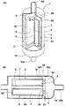
図1(A),1(B)に示すように、本発明のフィルター組立体1は、金属製多孔体で構成された複数個の筒状の金属濾過体2…を、ベース部材3にかつ該筒状金属濾過体2…の外周面2o間に所定の隙間Sを隔てて離間して配置し、ベース部材3に固定されるとともに、これら前記金属濾過体…2をハウジング容器部5で被包し、構成している。図1(A)はその全体を一部断面で示す斜視図であり、図1(B)は、図1(A)の扁平面に沿う方向から見た断面図である。
As shown in FIGS. 1 (A) and 1 (B), a filter assembly 1 according to the present invention comprises a plurality of cylindrical
前記金属濾過体2は、金属多孔体を用いた筒状体であり、該金属濾過体2の外周面2oに、一連に連ねた平坦な偏平面6を有する横断面非円形状の筒状体であって、隣り合う前記金属濾過体2の偏平面6と向き合わせ任意距離を隔てて配置することにより、前記隙間Sを形成している。
The
この形態において前記金属濾過体2…は、前記扁平面6を具えた外周面2oを有する筒状基部2Aと、その先端を閉じる天板部2Bとにより内部に空所7を形成するキャップ状をなすとともに、後端には開口部2C形成しこの開口部2Cを前記ベース部材3に固定している。又本例では、前記偏平面6は、前記先端(天板部2B側)から後端(開口部2C側)まで連続した真直面をなし、他方の金属濾過体2の偏平面6、6を対向させたとき前記隙間Sを生じうる。
In this embodiment, the
なお偏平面6は、 図1(A)では前記金属濾過体2は筒状体の中心(本例では外周面2oにより外延が定まる面積の面積重心をいう)を通る中心線2xと直角な横断面において、該金属濾過体2が半円形をなすように切欠きした形状にすることで前記偏平面6を形成している。
In FIG. 1A, the
偏平面6は、該筒状体の前記任意横断面において、その全周長L0の5〜48%の幅寸法L1で、その全長に亘って形成された平坦部を含み、少なくとも該筒状体のいずれか一面側に形成してなる。なお偏平面6は、前記するように金属濾過体の周面上に設けられ、好ましくは直面(平面)状にして隣接する他方の金属濾過体の扁平面6と平行関係になるよう対向配置されるが、本発明はこのようなものだけでなく、例えば実質的に平坦と認識させるような比較的大きな曲率径で湾曲させたもの、あるいは前記隙間Sについても、前記扁平面同士が若干の開き角度を持つように勾配を付けて配置させたものも包含する。
なお前記間隙Sは、被処理流体の特性や処理条件に応じて任意距離が設定され、例えば半導体ガスなど気体状のものでは、1mm程度の比較的狭い間隔に配置しても、その隙間内に十分に浸入させて外周面全体を有効濾過面として活用できるのに対し、被処理流体が溶融ポリマーのような高粘性液体の場合は、それ自体の流動性が非常に低い為、該間隔Sが例えば5mm程度を下回るように狭い間隔にしたものでは、その隙間内への十分な浸入が達成できず、折角の構成を活かすことができない。したがって、このような高粘性流体の場合は、例えば5mm以上の間隔で配置し、合理的な上限配置間隔は20mm程度以下、好ましくは15mm以下とする
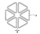
また該金属濾過体2に適用される断面形状としては、前記のように自在に選定できる。前記のように、偏平面6の中心線と直角断面での該偏平面6の寸法L1を、その周長L0の5〜48%とすることを条件として、金属濾過体2は前記半円形状の他、円弧状の弓形(トンネル形のような形状を含む)や、扇形、三角形、四角形、六角形等任意の形状のものが好適する。例えば前記半円形や弓形にしたものではその2本の濾過体によって、また扇形ではその数本を用いて断面円形に組立られ、同様に図3のように、正三角形状の濾過体の6本を配置したものでは、各対向面が各々濾過面として活用できる六角状の集合組立品となり、単一の六角状濾過体に比して約3倍の濾過面積をもたらすことができる。しかし、各濾過体が必要以上に小さくしたり多数本を併用するようなものでは、ベース部材2に設置する際の作業性が低下する為、設計にあたってはこうした点を考慮することが望まれる。
また本発明では、フィルター組立体に用いる各金属濾過体2は各々同一形状のものだけでなく、例えば断面形状や大きさの異なる数種の濾過体を各々複合配置することもでき、また、これら金属濾過体2は、例えばステンレス鋼、ニッケル、チタン等種々金属乃至合金による金属繊維や金属粉末を用いた多孔質な金属焼結体の他、ハイメッシュ製の金網等、従来公知の種々濾材を用いることができる。
特にステンレス鋼繊維及び/又はステンレス鋼粉末を単独乃至複合し、あるいは複層構造にして焼結したステンレス鋼焼結体は、高強度で耐圧性に優れるとともに、耐食性、耐熱性、非磁性をもたらすとともに、例えば溶接加工や絞り加工、曲げ加工などの後加工も容易なことから、本発明に好適するものの1つである。実施にあたっては、該焼結体が所定の空孔特性を備えるよう、事前に素材の仕様設定や製造工程、処理条件が調節される。
The
The gap S is set at an arbitrary distance according to the characteristics of the fluid to be treated and the processing conditions. For example, in the case of a gaseous substance such as a semiconductor gas, even if it is arranged at a relatively narrow interval of about 1 mm, it is within the gap. While the entire outer peripheral surface can be used as an effective filtration surface by sufficiently infiltrating, the fluid S itself has a very low fluidity when the fluid to be treated is a highly viscous liquid such as a molten polymer. For example, in a case where the distance is narrow so as to be less than about 5 mm, sufficient penetration into the gap cannot be achieved, and the folding structure cannot be utilized. Therefore, in the case of such a highly viscous fluid, for example, it is arranged at an interval of 5 mm or more, and a reasonable upper limit arrangement interval is about 20 mm or less, preferably 15 mm or less, and a cross-sectional shape applied to the
In the present invention, each
In particular, a stainless steel sintered body obtained by sintering a stainless steel fiber and / or stainless steel powder alone or in combination or having a multilayer structure, has high strength and excellent pressure resistance, and provides corrosion resistance, heat resistance, and non-magnetism. In addition, since post-processing such as welding, drawing, and bending is easy, it is one suitable for the present invention. In implementation, the material specification setting, manufacturing process, and processing conditions are adjusted in advance so that the sintered body has predetermined pore characteristics.
また本発明では、前記金属濾過体2の任意断面における周長L0と扁平面6の幅寸法L1の関係を規定し、該幅寸法L1/周長L0の比が5〜48%としている。例えば、図1(A)のような半円形の金属濾過体では、該偏平面6の比率は、L1/[L1+(πL1/2)]の関係から約39%となる。、
このように、金属濾過体2,2は、半円状の隣り合う2本の金属濾過体2の対向する偏平面6,6間の隙間Sを具えるため、フィルター組立体1は、前記ハウジング部材6の内容積当たりにおける内部の金属濾過体2…の合計濾過面積を増すことができ、全体として効率の良い濾過処理を可能とする。即ち、例えば前記断面半円形の金属濾過体2,2を用いるものでは、隙間S部分の扁平面6を含めて濾過面となしうるため、その全体の有効濾過面積は、従来の単一の円筒形濾過体を用いるものに比して約60%余り増大させることができ、同様に3本乃至6本に分割させた扇形のろ金属濾過体2…にすればその効果は該扁平面の数に比例して高まり、所定設置スペース内でより大きな濾過面積をもたらすことができる。
Moreover, in this invention, the relationship between the circumferential length L0 in the arbitrary cross section of the said
Thus, since the
なお、前記幅寸法(L1)の比率が5%未満のものでは、仮にその複数本を隣接配置するとしてもさほど大きな濾過面積の増大は期待できず、逆に48%を超える程大きくしたものでは、濾過体2自体が例えば薄板状断面のものになってその取扱いやベース部材に設置する際に困難をもたらすとともに、曲げ強度に劣るものとなる。故に、金属濾過体2の全外周長L0の5〜48%の寸法L1、より好ましくは10〜45%、更に好ましくは25〜40%とする。
When the ratio of the width dimension (L1) is less than 5%, a large increase in filtration area cannot be expected even if a plurality of them are arranged adjacent to each other. The
このように、金属濾過体2は、偏平面6,6間の間隙Sを持って前記ベース部材2上に離間配置され、隙間Sは、被濾過流体の用途、被処理流体の流動特性、設置作業性、粘性、基本流速等に基づき、金属濾過体2の大きさや配置状況、ハウジング部材容積などから全体としての濾過能力を増大する値を、解析し、又シミュレーションに基づき設定する。
Thus, the
フィルター組立体1は、前記し、かつ図1(A)及び図1(B)に示すごとく、前記金属濾過体2は開口部2Cでベース部材3に固着され、ベース部材3は、本例では円板状の基体3Aの先端面側(図1aの上側)に、前記間隙Sを隔てる金属濾過体6,6の形状に合わせて凹設した窪み3a、3aが形成され,かつその金属濾過体6の内部の前記空所7に通じる導孔9,9を設けている。窪み3aであることによりその周囲に位置合わせ用の段差状の小壁3cを形成している。
As described above and as shown in FIGS. 1 (A) and 1 (B), the filter assembly 1 is fixed to the
前記金属濾過体2の前記開口部2Cをベース部材3に固着するには、この開口部2Cを前記窪み3aに嵌着し、かつ窪み3aの底面3b、小壁3cに、例えば接着剤、溶接、ロウ付け、嵌合、圧接などリークの生じない種々方法を用いて固定する。このような窪み3aを設けることで、金属濾過体2の位置合わせを容易にし、リーク発生を防ぐとともに設置作業性を高め得る。
In order to fix the
こうして金属濾過体2を配置した前記ベース部材3には、更にその周囲に、ハウジング部材5を取付けする為の取付座3d1、取付座3d2が形成される。その取付け構造については、このような各取付座3d1,3d2を設けて周囲を溶接したものでも、あるいは本出願人が先の特許2813274号公報で提案したようにインロー嵌合によってリークなく一体化させたものなど、種々形態が採用される。またベース部材3は、前記ハウジング容器部5内にねじ込み方式で固着するように構成することもできる。
A mounting seat 3d1 and a mounting seat 3d2 for mounting the housing member 5 are further formed around the
このようにベース部材3の一方の取付座3d1には、前記金属濾過体2…を覆い外界と隔離する前記ハウジング容器部5が気密に固定され、他方側の取付座3d2には、各排出用の前記導孔9を覆って処理流体を集めて流出する排出口10Aを有するカバー部材10が、前記ハウジング容器部5と同様に気密に固定される。
その結果、ハウジング容器部5の導入口5Aから流入する被処理流体は、前記金属濾過体2、2で濾過処理され、流体中の不純物粒子が取り除かれた清浄流体だけが前記ベース部材3に設けた導孔9…を経て、カバー部材10の排出口10Aから次工程に送られる。
As described above, the housing container portion 5 that covers the
As a result, the fluid to be treated flowing from the
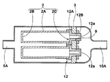
このように、前記金属濾過体2はベース部材3に直接取り付け得る他、例えば図2のように、金属濾過体2の開口部2Cに予め継手部材12を固着して、この継手部材12を介してベース部材3に取付けすることができる。
As described above, the
この継手部材12は、周囲にフランジを有し前記金属濾過体2の開口部2Cを沈めて嵌着しうる凹部12aを有する基板12Aに、前記導孔9を通り前記ベース部材3を通り抜けた外面にねじ部を有する筒部12Bを固着したもので、該継手部材12の前記ねじ部をナット締めすることで金属濾過体2を固定するものである。このような継手部材12によるものでは、例えば金属濾過体2を必要に応じて任意に個別交換することができ、かつフィルター組立体1の組立性を向上する。
This
なお前記金属濾過体2は、その用途、設置スペース等に応じて例えば長さ10〜1000mmで、かつその横断面方向の最大寸法が10〜300mm程度の筒状に成形されたものが用いられ、全長に亙って同形状かつ同寸法とした筒体の他、例えば該フィルター組立体が円錐台状になるように、各濾過体の周面を軸方向に沿って寸法変化させたものを含む。
The
又金属濾過体2は、例えば微細メッシュに織り上げられた金網製シートにより、その単体乃至複数を積層した膜状濾材や、金属繊維及び/又は金属粉末を所定厚さ、例えば厚さ0.1〜5mm程度の多孔質構造の板状に焼結成形した金属製板状濾材が用いられる。
In addition, the
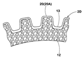
さらに必要に応じて、該金属濾過体2の一面側により耐圧性に優れ、かつ高強度の多孔性の支持層を積層配置した積層濾材2Dを用い得る他、本願第二発明に絡めて説明する例えば図4に示すように、その外周面を凹凸形成したものを用いることもできる。
Furthermore, if necessary, a
このような積層濾材2Dは、例えば本出願人が先に提案した国際公開第WO93/06912号パンフレットに示すように、例えば金属粉末により比較的粗大な空孔を持つ粉末焼結体等を支持体12とし、その一面側に実質的な濾過機能を持たせ得る微細粒子を所定厚さ堆積させた微細層13を前記支持体12に一体化したものを用いうる。同様に従来からフィルターの分野で補強材として採用されている、例えば粗大メッシュや、パンチングプレートなどを支持部材として用いることもできる。なお、前記金属濾過体2の大きさや濾材の構成は前記記載のものだけに限定されるものではなく、それ以外の種々設定が可能である。
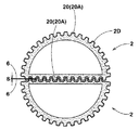
次に本発明のフィルター組立体について、他の発明の実施例を図5,その要部を示す図6により説明する。先の発明に用いた用語、概念は新たな説明を省略している。図5は、前記した発明のように筒形の金属製濾過体2を用いることにおいて共通し、その全周に亙って軸方向に伸びた複数の襞20Aなどの突起20を設けて、単位面積当たりにおける濾過面積の増大を図っている。突起20はこのように、軸方向に伸びた複数の襞20Aなどから構成できる。なお、前記中心線2x方向にのび各両側の凹部19から立ち上がる複数の襞20Aからなる突起20を形成している。
For example, as shown in International Publication No. WO 93/06912 pamphlet previously proposed by the present applicant, such a
Next, another embodiment of the filter assembly of the present invention will be described with reference to FIG. 5 and FIG. New explanations of terms and concepts used in the previous invention are omitted. FIG. 5 is common to the use of the cylindrical
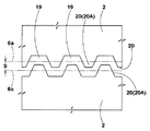
前記した発明に比して、この形態による前記金属濾過体2の少なくとも1つは、その外周面上に複数の突起20を具えるとともに、図6に略示するように、その任意横断面における該突起20の平均高さ(1/2H)の点を結ぶ仮想外周線で示すこととする。
そして、該仮想外周線が実質的に平坦になる偏平面6aを具えるとともに、その幅寸法L1が、該外周線の全周長L0の5〜48%となる一連の平坦な仮想扁平面6aとしている。前記発明との相違する点のみについて以下説明する。
Compared to the above-described invention, at least one of the
A series of flat virtual
前記仮想平均腺の仮想扁平面6aは、その平均腺における全周長(L0)の5〜48%の幅寸法(L1)になるように設定して、他方金属濾過体2の仮想扁平面6aと対向させ、かつ該襞20A同士が非接触状態で歯合し嵌り合うように襞20Aを位置ずらしする(図6に拡大して示す)とともに、その仮想平均腺同士が前記所定間隔Sで対向するよう配置されている。即ち他の発明においても仮想外周線の偏平面6A、6A間の寸法を隙間Sとしている。
The virtual
このような突起付の金属濾過体2については、例えば本出願人による特許文献1に見られるように、比較的粗大な空孔を持ち、予め表面に凹凸形状を付与した金属製の支持体12を、濾過層13を形成する微細粒子を予め懸濁された液中に入れて、その内周面側から減圧吸引させることで、支持体12の凹凸形状に沿って所定厚さ(例えば0.05〜0.5mm程度)の微細層を堆積させ、更に焼結一体化させる方法を応用することができる。なおその場合、前記支持体はその凹凸状の仮想線の一部が前記幅寸法で平坦化するように構成したものが用いられる。
また前記微細層13は、実質的な濾過機能を発揮するよう空孔径や空孔率が設定され、それに見合うように用いる微細粒子の種類、形状、粒子径、乃至吸引成形圧力などの条件が選択される。微細粒子の一例として、例えば粒子径10μm以下のアトマイズド粉末や、繊維径10μm以下でその50倍以下の長さを持つ金属短繊維が好適し、また前記両者を所定割合で混合した混合粒子を用いることもできる。このような形態のステンレス鋼短繊維については、例えば特許第3559529号が開示するものが用いられる。
As for the
The
この発明に係わる前記襞20Aの形状については、例えば高さH0.5〜10mm(好ましくは1〜3mm)で、円周方向のピッチPが1〜10mm(好ましくは2〜8mm)程度になるように形成したものが良好であるが、これに限定されるものではない。とは言え、前記ピッチPが必要以上に小さくかつ高さHを大きくしてきつい襞20Aを形成したものでは、前記したように襞凹部内への微細粒子の浸入が困難で、また他の濾過体の襞と非接触状態で嵌め合わせる際にも困難を伴う為、濾過体同士の配置間隔(S)を大きくすることが求められる。また本発明は、このように襞同士を嵌め合わせるものの他、更に大きな隙間(S)をもって離間配置させることもできる。
Regarding the shape of the
このような襞付濾過体を用いるフィルター組立体についてのその他の構成については、前記第一発明の説明及び以下具体例に沿って任意に設定される。
(具体例1)
繊維径12μmのステンレス鋼繊維でなる不織布と、その片面側に補強用の金網(0.25mm×100メッシュ)を積層して、厚さ2mmで空隙率75%に加圧焼結した焼結シートを作成し、これを用いて半径20mm、中心角度120°の扇形となる長さ200mmの扇形筒体とし、更に一方の上端側に該焼結シートから切り出した蓋体を重ね合わせて封止溶接し、その全体形状が扇形の筒状濾過体を得た。
About the other structure about the filter assembly using such a brazed filter body, it sets arbitrarily along description of said 1st invention and a specific example below.
(Specific example 1)
A non-woven fabric made of stainless steel fibers having a fiber diameter of 12 μm, and a reinforcing sheet (0.25 mm × 100 mesh) laminated on one side thereof, and sintered by pressure sintering to a porosity of 75% at a thickness of 2 mm This is used to form a fan-shaped cylindrical body with a length of 200 mm that has a radius of 20 mm and a central angle of 120 °, and a lid cut out from the sintered sheet is overlapped on one upper end side and sealed. As a result, a tubular filter body having an overall fan shape was obtained.
なお前記濾過体の内周面には、予め耐圧用の補強用粗大メッシュリテーナーを内装して、外周面からの濾過圧に耐え得るように構成したもので、その3本が全体として円形になるよう、各扁平面同士を配置間隔5mmで対向させベース板上にセットし、両者の接合面同士はロウ付によってリークなく固着するとともに、導入口と排出口を持つハウジング容器内に取り付けたフィルター組立体を得た。 The inner circumferential surface of the filter body is preliminarily provided with a coarse mesh retainer for pressure resistance so as to be able to withstand the filtration pressure from the outer circumferential surface, and three of them are circular as a whole. As shown in the figure, the flat surfaces are set to face each other at an arrangement interval of 5 mm and are set on the base plate, and the joint surfaces of both are fixed without leakage by brazing, and the filter assembly is mounted in a housing container having an inlet and an outlet. A solid was obtained.
この構成において、他方濾過体と対向する前記濾過体の扁平面の幅寸法(L1)は、その全周(L0)の33%に相当し、本例ではこの3本が全体として円形になるように配置したことから、各扁平面が各々有効濾過面積として活用でき、従来のような同径寸法で形成した円筒形濾過体に比較して約2.9倍の濾過面積の増大が図れ、また被処理流体に、温度280℃の溶融ポリマーを加圧供給しても、前記扁平面同士の隙間内に十分に浸入させることができ、高効率のフィルター組立体が得られた。
(具体例2)
図4に示すように、その全周に亘って軸方向に伸びる凹凸を形成した断面半円形の筒状支持体を用いて、繊維径3μmで平均アスペクト比(長さ/繊維径×100)が6のステンレス鋼短繊維を水中に懸濁された懸濁液中に入れ、その内周面側を減圧吸引することで、前記支持体の凹凸面上に厚さ0.15mmの微細層を具えた積層構造を有し、これを1100℃の無酸化雰囲気での加熱炉で焼結処理して襞付濾過体を得た。
In this configuration, the width dimension (L1) of the flat surface of the filter body facing the other filter body corresponds to 33% of the entire circumference (L0), and in this example, these three are circular as a whole. Therefore, each flat surface can be used as an effective filtration area, and the filtration area can be increased by about 2.9 times as compared with a conventional cylindrical filter formed with the same diameter. Even when a molten polymer having a temperature of 280 ° C. was pressurized and supplied to the fluid to be treated, it could be sufficiently infiltrated into the gap between the flat surfaces, and a highly efficient filter assembly was obtained.
(Specific example 2)
As shown in FIG. 4, an average aspect ratio (length / fiber diameter × 100) is obtained with a fiber diameter of 3 μm using a cylindrical support having a semicircular cross section in which irregularities extending in the axial direction are formed over the entire circumference. 6 stainless steel short fibers are put into a suspension suspended in water, and the inner peripheral surface side is sucked under reduced pressure to provide a fine layer having a thickness of 0.15 mm on the uneven surface of the support. The laminated structure was sintered in a heating furnace in a non-oxidizing atmosphere at 1100 ° C. to obtain a brazed filter body.
得られた濾過体は、全体長さが50mmで、その全周にピッチP:3mm,ピッチ高さH:2mmの襞を具えるとともに、その襞の頂点と谷部の高さの1/2Hの点を結ぶ仮想平均腺が直径30mmの半円形状を持つもので、前記襞を設けることで、その有効濾過面積は襞を設けない平滑表面の場合に比して約1.33倍に高めることができた。
なお該濾過体の厚さは、その内周面側と前記仮想平均腺とで示される仮想厚さが2.5mmで、このような肉厚で凹凸を形成していることから、十分な耐圧強度を有するものであり、また前記したような微細構造の積層濾材であることから、実質的な濾過特性は0.01以下の高精度を備え、半導体の製造プロセスガスの高純度濾過に好適するものであった。
そこで、この濾過体2本を用いて、図4のようにその仮想平均腺の扁平面同士を約2mmの間隔で接触することなく嵌め合わせてベース部材上に取り付け、ハウジング容器で被包したインライン型のガス用フィルターとして用いた。
この構成によって、該フィルターの全体的な濾過面は、ほぼ同径の襞を持たない円筒形濾過体の約2.17倍となり、即ち設置スペースの面積比では1/5以下に省スペース化するものであった。濾過処理は特に問題なく良好に行うことができた。
The obtained filter body has an overall length of 50 mm, and has ridges with a pitch P of 3 mm and a pitch height H of 2 mm on the entire circumference, and ½H of the height of the ridges and valleys of the ridges. The virtual mean gland connecting the points has a semicircular shape with a diameter of 30 mm, and by providing the ridges, the effective filtration area is increased by about 1.33 times compared to a smooth surface without ridges. I was able to.
The filter body has a virtual thickness of 2.5 mm indicated by the inner peripheral surface side and the virtual average gland, and has such a thickness to form irregularities. Since it has strength and is a laminated filter medium with a fine structure as described above, the substantial filtration characteristics have a high accuracy of 0.01 or less, and it is suitable for high-purity filtration of semiconductor manufacturing process gases. It was a thing.
Therefore, using these two filter bodies, the flat surfaces of the virtual mean glands are fitted to each other without contact at an interval of about 2 mm as shown in FIG. Used as a gas filter for the mold.
With this configuration, the overall filtration surface of the filter is approximately 2.17 times that of a cylindrical filter body having substantially the same diameter, that is, the installation space is reduced to 1/5 or less. It was a thing. The filtration process could be performed satisfactorily without any problem.
以上説明したように、本発明によれば、その外周面の一面を平坦化した扁平面を持つ断面非円形状の複数の筒状金属濾過体を、その扁平面同士を所定間隔で対向配置して構成したもので、その有効濾過面積を大幅に向上させることができ、しかも、本発明では濾過体は金属製でもあることから、高温状態や高腐食性の被処理流体である、例えば溶融ポリマーや半導体製造のプロセスガスなどに対して有効性が高いものである。また、該濾過体は、従来の濾過体と同様にそれ単独でも用い得る他、前記組立体の交換用部材として有用なものである。 As described above, according to the present invention, a plurality of cylindrical metal filter bodies having a non-circular cross section having a flat surface obtained by flattening one surface of the outer peripheral surface are arranged so that the flat surfaces are opposed to each other at a predetermined interval. In the present invention, since the filter body is also made of metal, it is a fluid to be treated in a high temperature state or highly corrosive, for example, a molten polymer. It is highly effective against process gases for semiconductor manufacturing. The filter body can be used alone as well as a conventional filter body, and is useful as a replacement member for the assembly.
1 フィルター組立体
2 金属濾過体
2A 筒状基体
2B 天板部
2C 開口部
3 ベース部材
5 ハウジング容器部
6 偏平面
6a 仮偏平面
20 突起
20A 襞
DESCRIPTION OF SYMBOLS 1
Claims (9)
前記金属濾過体は、その任意横断面において、該金属濾過体の全外周長L0の5〜48%の寸法L1で、一連の平坦な扁平面となる横断面非円形状の筒状体でなり、かつ該扁平面を他方の金属濾過体の扁平面と対向させ前記隙間Sを形成することを特徴とするフィルター組立体。 Open ends of a plurality of cylindrical metal filter bodies made of a metal porous body and having a top plate closed are spaced apart from the base member with a gap S between the cylindrical metal filter bodies. And the metal filter body is configured to be separated from the outside by a housing container part,
The metal filter body is a cylindrical body having a non-circular cross section that is a series of flat flat surfaces having a dimension L1 of 5 to 48% of the total outer peripheral length L0 of the metal filter body in an arbitrary cross section. And the said flat surface is made to oppose the flat surface of the other metal filter body, and the said clearance gap S is formed, The filter assembly characterized by the above-mentioned.
前記金属濾過体の少なくとも1つは、その外周面上に複数の突起を具えるとともに、その任意横断面において、前記突起の平均高さ(1/2H)の点を結ぶ仮想外周線における全外周長L0の5〜48%の寸法L1で、一連の平坦な扁平面となる横断面非円形状の筒状体でなり、かつ該扁平面を他方の金属濾過体の偏平面と対向させ前記隙間Sを形成することを特徴とするフィルター組立体。 Open ends of a plurality of cylindrical metal filter bodies made of a metal porous body and having a top plate closed are spaced apart from the base member with a gap S between the cylindrical metal filter bodies. And the metal filter body is configured to be separated from the outside by a housing container part,
At least one of the metal filter bodies has a plurality of protrusions on the outer peripheral surface thereof, and the entire outer periphery of a virtual outer peripheral line connecting points of the average height (1 / 2H) of the protrusions in an arbitrary cross section The gap L 5 is a dimension L1 that is 5 to 48% of the length L0, and is a cylindrical body having a non-circular cross section that is a series of flat flat surfaces, and the flat surface is opposed to the flat surface of the other metal filter body. A filter assembly characterized by forming S.
その任意断面において、該金属濾過体の全外周長L0の5〜48%の寸法L1で一連の平坦な扁平面となる横断面非円形状の筒状体で構成したことを特徴とする金属濾過体。 A metal filter body used for the filter assembly according to any one of claims 1 to 8,
Metal filtration characterized by comprising a cylindrical body having a non-circular cross-section having a series of flat flat surfaces with a dimension L1 of 5 to 48% of the total outer peripheral length L0 of the metal filter body in an arbitrary cross section. body.
Priority Applications (1)
| Application Number | Priority Date | Filing Date | Title |
|---|---|---|---|
| JP2008325974A JP5006865B2 (en) | 2008-12-22 | 2008-12-22 | Filter assembly for filtering gas for semiconductor manufacturing |
Applications Claiming Priority (1)
| Application Number | Priority Date | Filing Date | Title |
|---|---|---|---|
| JP2008325974A JP5006865B2 (en) | 2008-12-22 | 2008-12-22 | Filter assembly for filtering gas for semiconductor manufacturing |
Publications (2)
| Publication Number | Publication Date |
|---|---|
| JP2010142785A true JP2010142785A (en) | 2010-07-01 |
| JP5006865B2 JP5006865B2 (en) | 2012-08-22 |
Family
ID=42563768
Family Applications (1)
| Application Number | Title | Priority Date | Filing Date |
|---|---|---|---|
| JP2008325974A Active JP5006865B2 (en) | 2008-12-22 | 2008-12-22 | Filter assembly for filtering gas for semiconductor manufacturing |
Country Status (1)
| Country | Link |
|---|---|
| JP (1) | JP5006865B2 (en) |
Cited By (8)
| Publication number | Priority date | Publication date | Assignee | Title |
|---|---|---|---|---|
| WO2011162293A1 (en) | 2010-06-23 | 2011-12-29 | 日本化成株式会社 | Inorganic-organic hybrid material, optical material using same, and inorganic-organic composite composition |
| WO2012106149A2 (en) | 2011-02-04 | 2012-08-09 | Entegris, Inc. | Porous metal membrane of sintered powders and metal fibers |
| CN102873806A (en) * | 2012-10-23 | 2013-01-16 | 苏州嘉银绝缘材料有限公司 | Resin stock solution filter mechanism of polyimide film casting machine |
| CN103349869A (en) * | 2013-07-22 | 2013-10-16 | 王东伟 | Compound high-flux stainless steel metal sintered mesh filter element and manufacturing method thereof |
| JP2015513637A (en) * | 2012-03-01 | 2015-05-14 | スカニア シーブイ アクチボラグ | Filter housing and air filter unit for combustion engines |
| JP2019173771A (en) * | 2018-03-27 | 2019-10-10 | 日本精線株式会社 | Gas filter and gas supply device including the same |
| CN113304524A (en) * | 2021-05-26 | 2021-08-27 | 中国农业大学 | Self-cleaning net type filter for micro-irrigation and structure optimization design method thereof |
| CN114570137A (en) * | 2022-03-22 | 2022-06-03 | 美埃(中国)环境科技股份有限公司 | Novel dust removal filter cartridge filter |
Citations (15)
| Publication number | Priority date | Publication date | Assignee | Title |
|---|---|---|---|---|
| US2771153A (en) * | 1955-04-20 | 1956-11-20 | Allied Chem & Dye Corp | Filter apparatus |
| JPS4910881A (en) * | 1972-05-31 | 1974-01-30 | ||
| JPS57179062A (en) * | 1981-04-28 | 1982-11-04 | Nippon Soken | Porous ceramic structural body and manufacture |
| JPS6377506A (en) * | 1986-09-18 | 1988-04-07 | ハワ−ド・テイ−・デグラ−フエンライド | Filter cartridge and filter device |
| JPS6418423A (en) * | 1987-07-15 | 1989-01-23 | Piyuaron Japan Kk | Micro-filter for use in filtering air |
| JPH03175141A (en) * | 1989-12-04 | 1991-07-30 | Aisan Ind Co Ltd | Fuel filter for internal combustion engine |
| JPH0422404A (en) * | 1990-05-18 | 1992-01-27 | Kirin Brewery Co Ltd | Filtering system |
| JPH0985276A (en) * | 1995-09-27 | 1997-03-31 | Nok Corp | Aeration stirring type substrate decomposing method and apparatus therefor |
| JP2001162112A (en) * | 1999-12-09 | 2001-06-19 | Atlas:Kk | Porous filter, and fluid cleaning method and device using the same |
| JP2001513148A (en) * | 1997-03-07 | 2001-08-28 | メトウリクス システムズ カンパニー,エル.ピー. | Modular filter system for molten metal |
| JP2002336847A (en) * | 2001-05-17 | 2002-11-26 | Hitachi Ltd | Water purifier |
| JP2003205213A (en) * | 2002-01-15 | 2003-07-22 | Nippon Seisen Co Ltd | Filter apparatus |
| JP2004074086A (en) * | 2002-08-21 | 2004-03-11 | Nippon Seisen Co Ltd | Filter assembly |
| JP2004526910A (en) * | 2001-01-13 | 2004-09-02 | ダブリュ.エル.ゴア アンド アソシエーツ(ユーケー)リミティド | Cryogenic liquid delivery system with microporous phase separator |
| WO2007021409A1 (en) * | 2005-08-11 | 2007-02-22 | University Of Washington | Separation and concentration channel with determined pore shape |
-
2008
- 2008-12-22 JP JP2008325974A patent/JP5006865B2/en active Active
Patent Citations (15)
| Publication number | Priority date | Publication date | Assignee | Title |
|---|---|---|---|---|
| US2771153A (en) * | 1955-04-20 | 1956-11-20 | Allied Chem & Dye Corp | Filter apparatus |
| JPS4910881A (en) * | 1972-05-31 | 1974-01-30 | ||
| JPS57179062A (en) * | 1981-04-28 | 1982-11-04 | Nippon Soken | Porous ceramic structural body and manufacture |
| JPS6377506A (en) * | 1986-09-18 | 1988-04-07 | ハワ−ド・テイ−・デグラ−フエンライド | Filter cartridge and filter device |
| JPS6418423A (en) * | 1987-07-15 | 1989-01-23 | Piyuaron Japan Kk | Micro-filter for use in filtering air |
| JPH03175141A (en) * | 1989-12-04 | 1991-07-30 | Aisan Ind Co Ltd | Fuel filter for internal combustion engine |
| JPH0422404A (en) * | 1990-05-18 | 1992-01-27 | Kirin Brewery Co Ltd | Filtering system |
| JPH0985276A (en) * | 1995-09-27 | 1997-03-31 | Nok Corp | Aeration stirring type substrate decomposing method and apparatus therefor |
| JP2001513148A (en) * | 1997-03-07 | 2001-08-28 | メトウリクス システムズ カンパニー,エル.ピー. | Modular filter system for molten metal |
| JP2001162112A (en) * | 1999-12-09 | 2001-06-19 | Atlas:Kk | Porous filter, and fluid cleaning method and device using the same |
| JP2004526910A (en) * | 2001-01-13 | 2004-09-02 | ダブリュ.エル.ゴア アンド アソシエーツ(ユーケー)リミティド | Cryogenic liquid delivery system with microporous phase separator |
| JP2002336847A (en) * | 2001-05-17 | 2002-11-26 | Hitachi Ltd | Water purifier |
| JP2003205213A (en) * | 2002-01-15 | 2003-07-22 | Nippon Seisen Co Ltd | Filter apparatus |
| JP2004074086A (en) * | 2002-08-21 | 2004-03-11 | Nippon Seisen Co Ltd | Filter assembly |
| WO2007021409A1 (en) * | 2005-08-11 | 2007-02-22 | University Of Washington | Separation and concentration channel with determined pore shape |
Cited By (11)
| Publication number | Priority date | Publication date | Assignee | Title |
|---|---|---|---|---|
| WO2011162293A1 (en) | 2010-06-23 | 2011-12-29 | 日本化成株式会社 | Inorganic-organic hybrid material, optical material using same, and inorganic-organic composite composition |
| WO2012106149A2 (en) | 2011-02-04 | 2012-08-09 | Entegris, Inc. | Porous metal membrane of sintered powders and metal fibers |
| JP2015513637A (en) * | 2012-03-01 | 2015-05-14 | スカニア シーブイ アクチボラグ | Filter housing and air filter unit for combustion engines |
| CN102873806A (en) * | 2012-10-23 | 2013-01-16 | 苏州嘉银绝缘材料有限公司 | Resin stock solution filter mechanism of polyimide film casting machine |
| CN102873806B (en) * | 2012-10-23 | 2015-08-26 | 苏州嘉银绝缘材料有限公司 | Machine for Polyimide Film resin stoste filter mechanism |
| CN103349869A (en) * | 2013-07-22 | 2013-10-16 | 王东伟 | Compound high-flux stainless steel metal sintered mesh filter element and manufacturing method thereof |
| JP2019173771A (en) * | 2018-03-27 | 2019-10-10 | 日本精線株式会社 | Gas filter and gas supply device including the same |
| JP7011509B2 (en) | 2018-03-27 | 2022-01-26 | 日本精線株式会社 | Gas filter and gas supply device equipped with it |
| CN113304524A (en) * | 2021-05-26 | 2021-08-27 | 中国农业大学 | Self-cleaning net type filter for micro-irrigation and structure optimization design method thereof |
| CN113304524B (en) * | 2021-05-26 | 2022-06-28 | 中国农业大学 | Self-cleaning net type filter for micro-irrigation and structure optimization design method thereof |
| CN114570137A (en) * | 2022-03-22 | 2022-06-03 | 美埃(中国)环境科技股份有限公司 | Novel dust removal filter cartridge filter |
Also Published As
| Publication number | Publication date |
|---|---|
| JP5006865B2 (en) | 2012-08-22 |
Similar Documents
| Publication | Publication Date | Title |
|---|---|---|
| JP5006865B2 (en) | Filter assembly for filtering gas for semiconductor manufacturing | |
| EP1040860B1 (en) | Metal filter | |
| CA2497891C (en) | Filter plate | |
| US3581902A (en) | Filter made from powdered metal | |
| US5904178A (en) | Gas filter for regulator valve, and improved regulator valve employing the filter | |
| CN101291738A (en) | Perforated member | |
| US20020195388A1 (en) | Advanced leaf disc filter segment | |
| US9776111B2 (en) | Disc shaped filter element | |
| JP2006088081A (en) | Method for filtering highly viscous fluid | |
| EP2817077B1 (en) | Metal fibre web based filter | |
| JP2011522156A (en) | Filter media for aftertreatment of exhaust gas from internal combustion engines | |
| JP3538212B2 (en) | Precision laminated filter media | |
| JP4116366B2 (en) | Filter assembly | |
| KR101985706B1 (en) | Porous metal filter | |
| JP4065132B2 (en) | Filter device | |
| US5705071A (en) | Pleated ceramic filter | |
| US20190001242A1 (en) | Filter with non-horizontal cavity | |
| JP2015009235A (en) | Precision laminated filter | |
| JP3515192B2 (en) | Brazing structure of porous metal body and method of manufacturing the same | |
| JP2002518167A (en) | Purification assembly and purification method | |
| RU2635802C1 (en) | Filter | |
| WO2022208678A1 (en) | Filter | |
| JP6120132B2 (en) | Method for producing metal tubular filter for high purity gas | |
| CN210543966U (en) | High strength candle formula filter core | |
| JP2606925Y2 (en) | Laminated filter media |
Legal Events
| Date | Code | Title | Description |
|---|---|---|---|
| A621 | Written request for application examination |
Free format text: JAPANESE INTERMEDIATE CODE: A621 Effective date: 20110318 |
|
| A977 | Report on retrieval |
Free format text: JAPANESE INTERMEDIATE CODE: A971007 Effective date: 20111024 |
|
| A131 | Notification of reasons for refusal |
Free format text: JAPANESE INTERMEDIATE CODE: A131 Effective date: 20111101 |
|
| A521 | Request for written amendment filed |
Free format text: JAPANESE INTERMEDIATE CODE: A523 Effective date: 20111227 |
|
| TRDD | Decision of grant or rejection written | ||
| A01 | Written decision to grant a patent or to grant a registration (utility model) |
Free format text: JAPANESE INTERMEDIATE CODE: A01 Effective date: 20120522 |
|
| A01 | Written decision to grant a patent or to grant a registration (utility model) |
Free format text: JAPANESE INTERMEDIATE CODE: A01 |
|
| A61 | First payment of annual fees (during grant procedure) |
Free format text: JAPANESE INTERMEDIATE CODE: A61 Effective date: 20120525 |
|
| FPAY | Renewal fee payment (event date is renewal date of database) |
Free format text: PAYMENT UNTIL: 20150601 Year of fee payment: 3 |
|
| R150 | Certificate of patent or registration of utility model |
Ref document number: 5006865 Country of ref document: JP Free format text: JAPANESE INTERMEDIATE CODE: R150 Free format text: JAPANESE INTERMEDIATE CODE: R150 |
|
| R250 | Receipt of annual fees |
Free format text: JAPANESE INTERMEDIATE CODE: R250 |
|
| R250 | Receipt of annual fees |
Free format text: JAPANESE INTERMEDIATE CODE: R250 |
|
| R250 | Receipt of annual fees |
Free format text: JAPANESE INTERMEDIATE CODE: R250 |
|
| R250 | Receipt of annual fees |
Free format text: JAPANESE INTERMEDIATE CODE: R250 |
|
| R250 | Receipt of annual fees |
Free format text: JAPANESE INTERMEDIATE CODE: R250 |
|
| R250 | Receipt of annual fees |
Free format text: JAPANESE INTERMEDIATE CODE: R250 |
|
| R250 | Receipt of annual fees |
Free format text: JAPANESE INTERMEDIATE CODE: R250 |
|
| R250 | Receipt of annual fees |
Free format text: JAPANESE INTERMEDIATE CODE: R250 |
|
| R250 | Receipt of annual fees |
Free format text: JAPANESE INTERMEDIATE CODE: R250 |
|
| R250 | Receipt of annual fees |
Free format text: JAPANESE INTERMEDIATE CODE: R250 |