JP2010142767A - Fluid work monitoring device - Google Patents
Fluid work monitoring device Download PDFInfo
- Publication number
- JP2010142767A JP2010142767A JP2008325028A JP2008325028A JP2010142767A JP 2010142767 A JP2010142767 A JP 2010142767A JP 2008325028 A JP2008325028 A JP 2008325028A JP 2008325028 A JP2008325028 A JP 2008325028A JP 2010142767 A JP2010142767 A JP 2010142767A
- Authority
- JP
- Japan
- Prior art keywords
- fluid
- work
- cleaning
- sensor
- type
- Prior art date
- Legal status (The legal status is an assumption and is not a legal conclusion. Google has not performed a legal analysis and makes no representation as to the accuracy of the status listed.)
- Granted
Links
Images

Landscapes
- Cleaning By Liquid Or Steam (AREA)
Abstract
【課題】外部機器からの信号を用いることなく流体による作業工程の良否を独自に判断する流体作業監視装置を提供する。
【解決手段】制御部と、記録手段と、洗浄液の循環経路の所定の部位に臨ませて設けた流体の状態を検出するための少なくとも一つのセンサとを有し、前記記録手段には予め外部機器が実行する流体による複数の作業工程の種別特徴と良否判定に用いる作業工程の種別に応じた所定の基準値が格納されており、前記制御部は前記センサの経時的な出力変化と前記作業工程の種別特徴とを比較観察し、現在行われている流体による作業工程の種別を外部機器からの信号を用いることなく独自に判定する工程種別判定手段と、前記センサの出力が作業工程の種別に応じた所定の基準値を充たす状態が一定時間継続したかどうかにより、当該作業工程の良否を独自に判断する作業工程良否判断手段とを備える。
【選択図】図2Provided is a fluid work monitoring device that uniquely determines whether a fluid work process is good or not without using a signal from an external device.
A control unit, a recording unit, and at least one sensor for detecting a state of a fluid provided facing a predetermined portion of a circulation path of a cleaning liquid, the recording unit including an external device in advance. A predetermined reference value corresponding to a type characteristic of a plurality of work processes by a fluid executed by the device and a type of work process used for pass / fail judgment is stored, and the control unit changes output with time of the sensor and the work A process type determination means for comparing and observing the type characteristics of the process and independently determining the type of work process performed by the current fluid without using a signal from an external device, and the output of the sensor is the type of the work process And a work process pass / fail judgment means for independently judging pass / fail of the work process depending on whether or not a state satisfying a predetermined reference value according to the condition continues for a certain period of time.
[Selection] Figure 2
Description
本発明は、牛体搾乳機や食品製造装置のような流体を扱う機器の洗浄や殺菌作業、また工作物の製造における表面処理・コーティング作業のように、一定の性質を持った流体と接触させることにより機器のメンテナンスや工作物の処理を行う流体作業工程において、作業の進捗とその良否を自動判定するための装置、特に複数の異なる流体を使用する流体作業の監視装置に関する。 The present invention is in contact with a fluid having a certain property, such as cleaning and sterilizing operations of fluid handling equipment such as bovine milking machines and food manufacturing apparatuses, and surface treatment / coating operations in the manufacture of workpieces. The present invention relates to a device for automatically determining the progress of work and its quality in a fluid work process in which equipment maintenance and workpiece processing are performed, and more particularly to a fluid work monitoring device that uses a plurality of different fluids.
搾乳機においては、搾乳作業の前後に、水、酸性・アルカリ性洗浄液等の洗浄水を搾乳ラインに所定の順序で流したり、バルククーラーの内部を循環させたりして洗浄を行っている。通常の洗浄手順では、まず常温の水やぬるま湯による最初のかけすすぎにより、乳成分を洗い流す。次にアルカリ性洗浄液での循環洗浄による脂肪分の分解洗浄や、酸による無機物類の除去などを順次行って溶けにくい汚れを除去する。最後に水やぬるま湯等で最後のかけすすぎを行って洗浄液を洗い流す。搾乳の前にさらに殺菌液による除菌工程を行うこともある。 In the milking machine, before and after the milking operation, washing is performed by flowing washing water such as water and acidic / alkaline washing liquid through the milking line in a predetermined order or circulating the inside of the bulk cooler. In a normal washing procedure, milk components are first washed away by first rinsing with room temperature water or lukewarm water. Next, the dirt that is difficult to dissolve is removed by sequentially performing decomposition cleaning of fat by circulation cleaning with an alkaline cleaning liquid and removal of inorganic substances by acid. Finally, rinse with water or lukewarm water to wash away the cleaning solution. A sterilization step using a bactericidal solution may be further performed before milking.
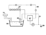
例えば、図7に示す特開平9−56288号公報記載の真空配管式搾乳機では、予め洗浄液供給装置70より所定量の洗浄液を洗浄槽80に貯溜しておき、送乳ポンプPの吐出側配管81を洗浄槽80内に臨ませると共に、洗浄槽80の上方を通る集乳配管83に設けた接続口84に搾乳ユニットを吊下げて、各ティートカップ85の先端を洗浄槽80内の洗浄液に浸すことにより、洗浄槽80から、ティートカップ85、ミルククロー86、集乳配管83、レシーバージャー87、送乳ポンプPを経由する洗浄液の循環回路を形成する。そして送乳ポンプPを駆動することにより洗浄液を強制循環させて、集乳配管83と搾乳ユニットを自動洗浄する。洗浄終了時やかけ流し洗浄の場合には、送乳ポンプの吐出側配管に設けた排水弁88を開放し、戻った水や洗浄液を自動排出する。
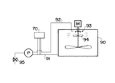
搾乳機のバルククーラーの洗浄においても、洗浄用のポンプを運転してタンクの内部に洗浄液・殺菌液を循環させ、自動洗浄することが知られている。バルククーラーの洗浄時のシステム構成は、例えば図8に示すようにバルククーラー90の排水配管91に洗浄ポンプPと洗浄液供給装置70を設けておき、洗浄ポンプPから洗浄用配管92を経てバルククーラー90最上部のノズル93にいたる洗浄液の循環回路を形成する。そして分配羽根94を回転させながら洗浄ポンプPを駆動させることにより洗浄液をバルククーラー90内部に満遍なくゆきわたらせて自動洗浄する。洗浄終了時やかけ流し洗浄の場合には、洗浄ポンプの下流側に設けた排水弁95を開放し、戻った水や洗浄液を自動排出する。
In washing a milking machine's bulk cooler, it is known to operate a washing pump to circulate a washing liquid / sterilizing liquid inside a tank and perform automatic washing. For example, as shown in FIG. 8, the system configuration at the time of cleaning the bulk cooler is provided with a cleaning pump P and a cleaning
また、機械部品等の製造において、工作物を所定の電解質溶液に浸して表面処理・コーティングを施すことがある。この場合も表面処理等に先立ってアルカリや酸による洗浄を行ったり、処理後に純水による洗浄を行うなど、複数の流体作業が行われる。 In the manufacture of machine parts and the like, surface treatment and coating may be performed by immersing a workpiece in a predetermined electrolyte solution. In this case as well, a plurality of fluid operations are performed such as cleaning with alkali or acid prior to surface treatment or the like, or cleaning with pure water after processing.
複数の工程からなる流体作業の良否判定においては、作業の進捗を参酌しながら工程に応じた判断基準を用いて作業の良否を判定する必要があったが、現在いずれの工程にあるかを独自に判断するのではなく、搾乳機制御装置や自動洗浄装置、或いは洗剤自動供給装置等、流体作業を制御する外部機器から受信した工程信号に基づいて判定を行っていた。そのため既設の制御装置や洗浄装置に追加設定する場合には、通信インターフェースの設定やプログラムの書き換えなどが必要になるため、容易に洗浄工程の良否判定機能を追加することができず、装置一式を新規導入せざるを得ず高額な投資となっていた。また、洗浄・殺菌工程のように自動・手動を使用者が選択できる場合において、作業者が自ら工程を管理する場合にも対応しにくいという問題があった。 In determining the quality of a fluid work consisting of multiple processes, it was necessary to determine the quality of the work using judgment criteria according to the process while taking into account the progress of the work. The determination is made based on a process signal received from an external device that controls the fluid operation, such as a milking machine control device, an automatic washing device, or an automatic detergent supply device. Therefore, when additional settings are made for existing control devices and cleaning devices, it is necessary to set the communication interface and rewrite the program, so it is not possible to easily add a pass / fail judgment function for the cleaning process. A new investment was unavoidable. In addition, when the user can select automatic / manual as in the cleaning / sterilization process, there is a problem that it is difficult for the operator to manage the process himself / herself.
特開2008−154470号公報記載の洗剤供給装置では、各洗剤を個別にタンクに貯留して順次搾乳機に供給する構成の洗剤供給装置において、洗剤タンクに洗剤の必要量を判定する水位センサと洗剤の種類を判定する洗剤センサ(電気伝導度センサ、静電容量センサ等)を設け、洗剤供給装置の制御部が各洗浄工程の開始後に所定のタイミングでこれらの出力を予め記憶された基準値と比較して、貯留された洗剤等の種類と量を確認し、その結果を表示部に表示するようにしている。しかし、この装置は洗剤タンク内の洗剤量と洗剤の種類をチェックするものであり、実際に配管内を循環する洗浄液等を直接チェックするものではなかった。
そこで本発明は、複数工程を含む流体作業の各工程の判断を、搾乳機制御装置や自動洗浄装置等の外部機器からの工程信号に基づくことなく、スタンドアローンの状態で独自判定することが可能であり、既存の制御装置や洗浄装置に容易に追加設定できる合理的な洗浄殺菌工程等の監視手段を提供することを目的とする。 Therefore, according to the present invention, the determination of each process of the fluid work including a plurality of processes can be uniquely determined in a stand-alone state without being based on a process signal from an external device such as a milking machine control device or an automatic cleaning device. It is an object of the present invention to provide a monitoring means such as a rational cleaning and sterilization process that can be easily added to an existing control device or cleaning device.
請求項1記載の発明は、他の外部機器が実行している流体による作業の良否を判断するための流体作業監視装置であって、制御部と、記録手段と、洗浄液の循環経路の所定の部位に臨ませて設けた流体の状態を検出するための少なくとも一つのセンサとを有し、前記記録手段には予め外部機器が実行する流体による作業工程の種別特徴と良否判定に用いる作業工程の種別に応じた所定の基準値が格納されており、前記制御部によって前記センサの全部またはいずれかの経時的な出力変化と前記作業工程の種別特徴とを比較観察し、その結果により現在行われている流体による作業工程の種別を外部機器からの信号を用いることなく独自に判定する工程種別判定手段と、前記センサの全部またはいずれかの出力が前記良否判断に用いる作業工程の種別に応じた所定の基準値を充たす状態が一定時間継続したかどうかにより、外部機器からの信号を用いることなく当該作業工程の良否を独自に判断する作業工程良否判断手段とを備えていることを特徴とする流体作業監視装置により、上記の課題を解決する。
The invention according to
本発明に用いる流体の状態を検出するためのセンサとしては、温度センサや、電気伝導度センサ・pHセンサなどの水質(流体質)センサを用いることができ、流体について実施される作業の性質により様々なものを組み合わせて使用することができる。センサの経時的な出力変化を観察するとは、現在のセンサの出力と併せてそれまでの出力の推移を参酌しながら工程種別の判定を行うことをいい、好ましくは、記録手段に予め作業工程の順序と、各作業工程の種別特徴(作業工程を判定するための各センサ出力の閾値)を記録しておき、次回に行われるべき作業工程の種別特徴を示す基準値を記録手段から呼び出し、前記センサの出力と繰り返し比較することにより、現在行われている作業工程の種別を判定し、記録手段に格納する。従って、複数の工程からなる流体作業であっても、当該作業工程の制御機器からの入力を用いずに作業工程の進捗を判断し、適切な種別特徴を呼び出して良否判断を行うことができる。 As a sensor for detecting the state of the fluid used in the present invention, a water quality (fluid quality) sensor such as a temperature sensor, an electrical conductivity sensor, or a pH sensor can be used, depending on the nature of the work performed on the fluid. Various things can be used in combination. Observing the change in the output of the sensor over time refers to determining the process type while taking into account the transition of the output so far along with the current output of the sensor. Record the order and type characteristics of each work process (threshold value of each sensor output for determining the work process), call a reference value indicating the type characteristics of the work process to be performed next time from the recording means, By repeatedly comparing with the output of the sensor, the type of work process currently being performed is determined and stored in the recording means. Therefore, even in a fluid work consisting of a plurality of processes, the progress of the work process can be determined without using an input from the control device of the work process, and an appropriate type feature can be called to make a pass / fail determination.
良否判断に用いる基準値を充たす状態が一定時間継続したかどうかの判断は、センサの出力が基準値を充たす状態が一定時間繰り返されるかどうか、又は測定期間中に当該状態が一定回数表れたかどうかを判断することにより行うことができる。一定時間とは固定値でも各工程ごとに異なる値でも良いが、異なる値とする場合は基準値の一部として記録手段に格納することが好ましい。 Whether or not the state satisfying the reference value used for pass / fail judgment has continued for a certain period of time is determined by whether or not the state where the sensor output satisfies the reference value is repeated for a certain period of time, or whether the state appears a certain number of times during the measurement period This can be done by judging. The fixed time may be a fixed value or a different value for each process. However, when the value is different, it is preferably stored in the recording means as a part of the reference value.
本発明の流体作業監視装置では、温度センサ・流体質センサの出力を考慮して現在の工程が何であるかを自ら判断でき、そのうえで基準を満たす温度・流体質が継続した時間を積算することにより現在行われている工程の良否を判断するので、搾乳機制御装置、自動洗浄装置等の外部機器と通信しなくても独立に洗浄の良否判定を行うことができ、既存の装置に追加することで流体作業の自動監視機能を利用することが可能である。 In the fluid work monitoring device of the present invention, it is possible to determine by itself what the current process is in consideration of the output of the temperature sensor / fluid quality sensor, and then by integrating the time during which the temperature / fluid quality satisfying the standard is accumulated. Since the quality of the current process is judged, the quality of washing can be determined independently without communication with external equipment such as a milking machine control device, automatic washing device, etc. It is possible to use the automatic monitoring function of fluid work.
請求項2記載の発明は、前記流体による作業工程が、洗浄工程を含むことを特徴とする請求項1記載の流体作業監視装置により、上記の課題を解決する。例えば食品製造装置のメンテナンスや機械部品等の表面処理前後の洗浄工程などはこれに相当する。好ましくは、流体作業監視装置は温度センサと洗剤等の種類や濃度によって異なる検出信号を出力するような一種以上の水質(流体質)センサ、例えば電気伝導度センサや、pHセンサを備えている。例えば前記記録手段には洗浄工程の区別と良否判定に用いる温度・流体質・継続時間の基準値が格納されており、前記制御部は、温度センサ及び流体質センサの全部またはいずれかの出力を基準値と比較し、その結果により現在行われている洗浄工程を自己判定する洗浄工程自己判定手段と、温度センサ及び流体質センサの全部またはいずれかの出力が基準を充たす状態が一定時間継続したかどうかにより洗浄工程の良否を判断する洗浄工程良否判断手段とを備えることになる。搾乳機の洗浄装置を監視する場合、液温はすすぎ・殺菌工程では35〜50℃程度に保たれ、洗浄工程においては60℃程度に上昇するので、現在いずれの工程にあるかを判断するのに有効である流体質センサによる洗剤の判別を液温による工程判断と併用することにより、洗浄作業の進捗とその良否を判定することができる。
The invention according to
好ましくは、前記流体質センサとして電気伝導度センサとpHセンサの両方を備えることにより、洗浄工程の進捗と良否とをより正確に判断できる。電気伝導度は、通常の水では0に近いが、洗浄液が混入すると大きくなるので、すすぎ工程と、洗浄工程を区別するのに有効である。またpHの値は、通常の水道水では6ないし7であり、アルカリ洗剤が混入すると大きくなり、酸が混入すると小さくなるので、投入された洗剤の種類を判断するのに有効である。従って、流体質センサとしてこれらのセンサを併用することにより、洗浄工程とその良否を正確に判定することができる。 Preferably, by providing both the electrical conductivity sensor and the pH sensor as the fluid quality sensor, it is possible to more accurately determine the progress and quality of the cleaning process. The electric conductivity is close to 0 in normal water, but increases when the cleaning liquid is mixed, and is effective in distinguishing the rinsing process from the cleaning process. The pH value is 6 to 7 for normal tap water, and increases when an alkaline detergent is mixed, and decreases when an acid is mixed. Therefore, it is effective for determining the type of detergent that has been added. Therefore, by using these sensors together as a fluid quality sensor, it is possible to accurately determine the cleaning process and its quality.
請求項3記載の発明は、前記流体による作業工程が、殺菌工程を含むことを特徴とする請求項1記載の流体作業監視装置であり、請求項4記載の発明は、前記流体による作業工程が、洗浄工程と殺菌工程を組み合わせた工程であることを特徴とする請求項1記載の流体作業監視装置である。好ましくは、前記流体質センサとして電気伝導度センサとpHセンサとを備えることにより、殺菌工程の進捗と良否とをより正確に判断することができる。電気伝導度は、通常の水では0に近いが、殺菌液が混入すると大きくなるので、すすぎ工程と殺菌工程を区別するのに有効である。またpHの値は、通常の水道水では6ないし7であり、アルカリ洗剤が混入すると大きくなり、酸が混入すると小さくなるので、投入された洗剤又は殺菌液の種類を判断するのに有効である。従って、流体質センサとしてこれらのセンサを併用することにより、殺菌工程が行われているかの判別とその良否を正確に判定することができる。
The invention according to claim 3 is the fluid work monitoring apparatus according to
請求項5記載の発明は、前記センサが、温度センサ、電気伝導度センサ、pHセンサのうちの少なくとも一つであることを特徴とする請求項1から4のいずれかに記載の流体作業監視装置であり、工程の種類や設置環境等に応じて最適な構成を選択することができる。前述の通り、より正確な判定が必要な場合は、温度センサと少なくとも一つの流体質センサ(電気伝導度センサ若しくはpHセンサ)を備えることができ、さらに温度センサ、電気伝導度センサ、pHセンサの三種を備えることもできる。
The invention according to claim 5 is the fluid work monitoring device according to any one of
請求項6記載の発明は、流体作業監視装置がさらに表示手段と入力手段を備えたものである。表示手段には、現在行われている工程(搾乳機の洗浄作業であれば、酸洗浄・アルカリ洗浄・すすぎ)の表示や、作業の良否の判定を表示する。また工程の順序や基準値が異なる場合であっても、入力手段から設定を行うことにより複数のプログラムから選択したり、記録手段に格納された基準値を書き替えて対応することができるので、外部機器の制御プログラムが更新された場合にも容易に対応できる。 According to a sixth aspect of the present invention, the fluid work monitoring apparatus further includes display means and input means. The display means displays a process currently being performed (in the case of a milking machine cleaning operation, acid cleaning, alkali cleaning, rinsing) and a determination of whether the operation is good or bad. Even if the order of the processes and the reference values are different, it is possible to select from a plurality of programs by setting from the input means or to rewrite the reference values stored in the recording means, Even when the control program of the external device is updated, it can be easily handled.
請求項7記載の発明は、前記記録手段が、作業工程良否判断手段による良否判断の結果を累積して記録することを特徴とする請求項1から6のいずれか一項に記載の流体作業監視装置である。良否判断を記録することにより不良品の発生を未然に防いだり、異常な事態の発生した原因を容易に特定することができる。電気伝導度のデータ等を記録に残す場合には、液温の測定値を参照してこれらを補正すればいっそう正確な記録とすることができる。
The fluid work monitoring according to any one of
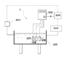
以下、図面を参照しながら、本発明の具体的な実施形態について説明する。図1は本発明に係る流体作業監視装置の一例として搾乳機器の洗浄殺菌工程に用いる洗浄工程等監視装置(流体作業監視装置)1を設置する場合の設置方法の概念図である。自動洗浄に使用する洗浄槽200や洗浄を行う搾乳機器に貯留される洗浄液に臨ませて、温度センサ107・電気伝導度センサ108・pHセンサ109を設置し、各センサの出力が洗浄工程等監視装置の制御ボックス(制御部)100に出力される。
Hereinafter, specific embodiments of the present invention will be described with reference to the drawings. FIG. 1 is a conceptual diagram of an installation method in the case of installing a monitoring device (fluid operation monitoring device) 1 for use in a washing and sterilization process for milking equipment as an example of a fluid operation monitoring device according to the present invention. A
なお、図1に示すように、制御ボックス100は、洗浄槽200の縁部や側面部に固定してもよく、或いは洗剤自動供給装置などの他の機器に固定したり、専用のスタンドなどに固定するなど、任意の設置方法でよい。
As shown in FIG. 1, the
また、自動洗浄装置300は、湯水バルブ301や洗剤自動供給装置302などと通信可能に構成されており、湯水バルブ301や洗剤自動供給装置302に指令を行うことで、搾乳機器のミルキングラインの自動洗浄を統括制御している。
Further, the
なお、洗浄殺菌工程監視装置1は、自動洗浄装置300や湯水バルブ301、洗剤自動供給装置302などからは独立したスタンドアローンに構成されており、それらの機器と信号の送受信がなされることはない。従って、それらの機器に影響を受けることはなく、また影響を与えることがないとともに、通信インターフェースの設定やプログラムの書き換えなども不要であるため、それらの機器がすでに設定されているシステムであっても別個独立して容易に追加設定することができる。
The cleaning and sterilization
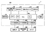
図2は制御回路の一例を示すブロック構成図である。本実施例の装置は搾乳機の洗浄・殺菌工程監視装置であり、作業者の設定により複数の洗浄工程と殺菌工程を監視可能なものである。また流体質センサとして電気伝導度センサとpHセンサの二種類を備えている。制御ボックス100において、マイコン101はA/D変換回路104〜106を介して、温度センサ107、電気伝導度センサ108、pHセンサ109と接続されている。温度センサ107は、洗浄液・殺菌液の循環する配管の内部に設置され、洗浄又は殺菌中、液温を測定・記憶し、アナログデータとしてA/D変換回路104に送信する。電気伝導度センサ108及びpHセンサ109は、洗浄又は殺菌中、それぞれ配管内の電気伝導度及びpH等の変化を測定・記憶し、アナログデータとしてA/D変換回路105及び106に送信する。A/D変換回路104〜106はこれらのデータをデジタルデータに変換する。
FIG. 2 is a block diagram showing an example of the control circuit. The apparatus of the present embodiment is a milking machine cleaning / sterilization process monitoring apparatus, and can monitor a plurality of cleaning processes and sterilization processes according to an operator's setting. Two types of fluid quality sensors are provided: an electrical conductivity sensor and a pH sensor. In the
制御回路100はまた、記録手段102、入力手段である開始・停止スイッチ113と洗浄・殺菌工程設定手段114、出力手段である表示装置110及び通信装置111を備え、さらに5V内蔵電源112を備えている。表示部は、装置の前面に設置された液晶表示装置等であり、各洗浄又は殺菌工程の判別結果と、洗浄・殺菌結果の良否を表示する。通信装置111は、無線通信手段等により、判別した工程の順序と良否判断の記憶データを、無線機能を備えたパソコン等に出力することができる。
The
マイコン101は、プログラムが実行されることによる論理ブロックとして、各A/D変換回路104〜106の信号を繰り返しモニタして記録手段102から読み出した基準値と比較して流体の質を判定する流体質判定手段101aと、さらに内部のタイマーにより条件成立後の経過時間を積算して、記録手段102から読み出した基準値と比較し、工程の進捗を自動洗浄装置の制御部などから工程信号を受信することなくスタンドアローンにより独自判定する工程種別判断手段である洗浄及び殺菌工程独自判断手段101b、及び洗浄及び殺菌工程の良否結果を判定する作業工程良否判断手段である洗浄及び殺菌工程良否判定手段101cを有している。記録手段102は不揮発性のメモリであり、良否判定と工程判定のプログラム、判定する工程の順序、判定基準値テーブル、現在の工程、過去の判定データ等が格納される。洗浄する対象(搾乳機・バルククーラー)や搾乳機制御装置や自動洗浄装置の機種によっては洗浄工程が異なる場合があるため、洗浄・殺菌工程設定手段113からの入力に従って、判定する工程・基準値等を選択設定できる方式となっている。設定内容は記録手段102に記録され、それに従ってマイコン101に各手順が呼び出される。
The microcomputer 101 repeats the signals of the A /
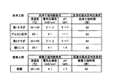
図3は記録手段102に格納される洗浄・殺菌工程良否判断基準値テーブルの一例であり、第一すすぎ工程、アルカリ洗浄工程、第二すすぎ工程、酸リンス工程、殺菌工程に対応する液温、電気伝導度、pH、継続時間の基準値がそれぞれ記憶されている。例えば第一すすぎ工程で液温35〜50℃、電気伝導度0〜2mS/cm、pH6〜7が60秒間継続したときは、すすぎ工程が良と判断されることを示している。本実施例の場合、このテーブルの基準値は工程進捗判断の基準値を兼ねており、例えば液温35〜50℃、電気伝導度0〜2mS/cm、pH6〜7が検出されたときは、第一すすぎ工程又は第二すすぎ工程が実行中と判断される。第一・第二すすぎのいずれに該当するかは、現在までの工程を参照して判定される。洗浄手順によっては、工程の判定に必ずしも液温・電気伝導度・pH値の測定値を全部考慮する必要はなく、液温が35℃〜50℃のときすすぎ又は殺菌工程、60℃以上のとき洗浄工程として判定することもできる。 FIG. 3 is an example of a cleaning / sterilization process pass / fail judgment reference value table stored in the recording means 102. The liquid temperature corresponding to the first rinsing process, the alkali cleaning process, the second rinsing process, the acid rinsing process, and the sterilizing process, Reference values for electrical conductivity, pH, and duration are stored. For example, when the liquid temperature of 35 to 50 ° C., the electrical conductivity of 0 to 2 mS / cm, and the pH of 6 to 7 are continued for 60 seconds in the first rinsing step, it indicates that the rinsing step is judged as good. In the case of this example, the reference value of this table also serves as a reference value for process progress judgment. For example, when a liquid temperature of 35 to 50 ° C., an electric conductivity of 0 to 2 mS / cm, and a pH of 6 to 7 are detected, It is determined that the first rinsing process or the second rinsing process is being executed. Whether it corresponds to the first or second rinsing is determined with reference to the processes up to now. Depending on the washing procedure, it is not always necessary to consider all measured values of the liquid temperature, electrical conductivity, and pH value in the determination of the process. Rinse or sterilization process when the liquid temperature is 35 ° C to 50 ° C, when the temperature is 60 ° C or higher It can also be determined as a cleaning step.
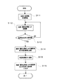
次に、図4〜6のフローチャートを参照しながら、洗浄・殺菌監視の具体的な判定手順を説明する。本実施例では、記録手段121に設定された各工程について良否判定し、全ての工程で良であれば総合判定を良とし、表示装置に洗浄良と表示する。不良の工程があれば、表示装置に不良工程を全て表示する。例えば、図3のテーブルに従って洗浄・殺菌工程の監視を行うには、まず監視スタート後、液温・電気伝導度・pH値の全部又はいずれかの組み合わせにより「第一すすぎ工程」と判定する。「第一すすぎ工程」の良否判定後、液温・電気伝導度又はpH値の全部又はいずれかの組み合わせにより「アルカリ洗浄工程」と判定する。「アルカリ洗浄工程」の良否判定後、液温・電気伝導度又はpH値の全部又はいずれかの組み合わせにより「第二すすぎ工程」と判定する。「第二すすぎ工程」の良否判定後、液温・電気伝導度又はpH値の全部又はいずれかの組み合わせにより「酸リンス工程」と判定する。そして「酸リンス工程」の良否判定と全洗浄工程の総合判定後、液温・電気伝導度又はpH値の全部又はいずれかの組み合わせにより「殺菌工程」と判定する。 Next, a specific determination procedure for cleaning / sterilization monitoring will be described with reference to the flowcharts of FIGS. In this embodiment, whether each process set in the recording unit 121 is good or bad is determined. If all the processes are good, the overall determination is good, and the display device displays good cleaning. If there is a defective process, all the defective processes are displayed on the display device. For example, in order to monitor the cleaning / sterilization process according to the table of FIG. 3, first, after the start of monitoring, it is determined as the “first rinsing process” based on all or any combination of liquid temperature, electrical conductivity, and pH value. After the quality determination of the “first rinsing step”, the “alkaline cleaning step” is determined based on all or any combination of the liquid temperature, electrical conductivity, and pH value. After the pass / fail judgment of the “alkaline cleaning process”, the “second rinse process” is determined based on all or any combination of the liquid temperature, electrical conductivity, and pH value. After the quality determination of the “second rinsing step”, the “acid rinsing step” is determined based on all or any combination of the liquid temperature, electrical conductivity, and pH value. Then, after the quality determination of the “acid rinsing process” and the comprehensive determination of all the cleaning processes, the “sterilization process” is determined based on all or any combination of the liquid temperature, electrical conductivity, and pH value.
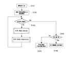
各工程における判定手順を詳細に説明すると、まず開始・停止スイッチ114の押下(S101)により洗浄・殺菌監視手順が開始し、各センサにより温度・電気伝導度・pHの測定を開始する(S102)。次に記録手段102に記憶された現在の工程をチェックし(S103)、全洗浄・殺菌工程が完了していれば各工程の良否をチェックする(S104)。全工程が良判定であれば表示装置に全工程結果が良である旨を表示する(S106)。不良工程があるときは、表示装置に不良工程と不良内容とを表示する(S105)。 The determination procedure in each step will be described in detail. First, the cleaning / sterilization monitoring procedure is started by pressing the start / stop switch 114 (S101), and the measurement of temperature, electrical conductivity, and pH is started by each sensor (S102). . Next, the current process stored in the recording means 102 is checked (S103), and if all the cleaning / sterilization processes are completed, the quality of each process is checked (S104). If all the processes are good, the display device displays that all the process results are good (S106). When there is a defective process, the defective process and the defect content are displayed on the display device (S105).
全洗浄・殺菌工程が完了していないときは、タイマーのカウントをスタート又はリセットする(S107)。そして次に判定すべき工程の判断基準値を記憶部より読み出し、一定間隔で、温度・電気伝導度・pHの測定値が判断基準を満足するかどうかをチェックする(S108)。温度・電気伝導度・pHの測定値判断基準が満足されないときは、タイマー124の値が所定の規定時間を超えているかチェックし(S109)、超えるまでS108のチェックを繰り返す。規定時間を超えたときは工程不明とする。S108で温度・電気伝導度・pHの測定値判断基準を満足したときはその旨を記録手段102に記録し、表示装置に洗浄又は殺菌の工程名を表示する(S110)。またS109で規定時間経過とされたときにも、判定不能である旨を記録手段102に記録した上で、表示装置にその旨を表示する。 When the entire cleaning / sterilization process is not completed, the timer count is started or reset (S107). Then, the determination reference value of the process to be determined next is read from the storage unit, and it is checked whether the measured values of temperature, electrical conductivity, and pH satisfy the determination standard at regular intervals (S108). If the temperature / electrical conductivity / pH measurement value criteria are not satisfied, it is checked whether the value of the timer 124 exceeds a predetermined specified time (S109), and the check of S108 is repeated until it exceeds. If the specified time is exceeded, the process is unknown. When the measurement value criteria for temperature, electrical conductivity, and pH are satisfied in S108, the fact is recorded in the recording means 102, and the cleaning or sterilization process name is displayed on the display device (S110). Also, when the specified time has elapsed in S109, the fact that the determination is impossible is recorded in the recording means 102 and then displayed on the display device.
次に、実行中と考えられる洗浄・殺菌工程の良否判定を行う。本実施例では、もし工程が判定不能であっても次工程が行われているものとして良否判定を行う。まずタイマーをリセットして、作業時間の計測を開始する(S111)。そして一定間隔で液温・電気伝導度・pHの測定値を積算していく(S112)。そして作業開始からの時間を洗浄・殺菌工程時間を記録手段102から読み出した時間基準値と比較し(S113)、基準値以下であればS112を繰り返す。基準値以上であればメモリに記録された液温・電気伝導度・pHの測定値を読み出し、これを基準値テーブルから読み出した各測定値の基準値と洗浄・殺菌工程時間基準値の積と比較し(S114)、判定結果を記録部に記録すると共に表示装置に表示する(S115)。良否判定を終えると温度・電気伝導度・pHの各積算値と洗浄工程時間のタイマーをリセットし(S116)、記録部に設定された手順に従って次の洗浄又は殺菌工程の判定に移る。なお上記の機器構成やアルゴリズムは一例であり、これに限られるものではない。 Next, the quality of the cleaning / sterilization process that is considered to be in progress is determined. In this embodiment, even if the process cannot be determined, it is determined that the next process is being performed. First, the timer is reset and measurement of the working time is started (S111). Then, the measured values of liquid temperature, electrical conductivity, and pH are integrated at regular intervals (S112). Then, the time from the start of the operation is compared with the time reference value obtained by reading the cleaning / sterilization process time from the recording means 102 (S113), and if it is less than the reference value, S112 is repeated. If the measured value is higher than the reference value, the measured value of the liquid temperature, electrical conductivity, and pH recorded in the memory is read, and this is the product of the reference value of each measured value read from the reference value table and the reference value of the cleaning / sterilization process time. The comparison is made (S114), and the determination result is recorded in the recording unit and displayed on the display device (S115). When the pass / fail determination is completed, the integrated values of temperature, electrical conductivity, and pH and the timer for the cleaning process time are reset (S116), and the next cleaning or sterilization process is determined according to the procedure set in the recording unit. In addition, said apparatus structure and algorithm are examples, and are not restricted to this.
以上のように、本実施形態では、流体作業監視装置を搾乳機器の洗浄殺菌工程の監視に用いることで、洗浄殺菌工程の不良による搾乳機器内部の細菌の増殖などの弊害を好適に防止することができる。 As described above, in the present embodiment, by using the fluid work monitoring device for monitoring the cleaning and sterilization process of the milking equipment, it is possible to suitably prevent harmful effects such as the growth of bacteria inside the milking equipment due to the poor cleaning and sterilization process. Can do.
また、この場合に、洗浄殺菌工程の監視は、自動洗浄装置300や洗剤自動供給装置302などの洗浄を実行する外部機器からの情報に依存することなく独自に行っているため、自動洗浄装置300や洗剤自動供給装置302などの異常時や洗浄槽200が破損して洗剤が漏れ出したような場合であっても確実に判定を行うことができる。
In this case, since the monitoring of the cleaning and sterilization process is independently performed without depending on information from an external device that performs cleaning such as the
また、前記実施形態は、本発明に係る流体作業監視装置として搾乳機器の洗浄殺菌工程に用いた洗浄殺菌工程監視装置を洗浄槽200に投入した例を示しているが、洗浄・殺菌工程設定手段114によってセンサの出力値や経過時間の設定を変更することで、バルククーラーなど当該搾乳機器の他の部位や、瓶詰めラインなどのまったく別の設備にもそのまま転用して使用することができるなど、フレキシブルに対応可能となっている。
Moreover, although the said embodiment has shown the example which supplied the washing | cleaning sterilization process monitoring apparatus used for the washing | cleaning sterilization process of milking equipment to the
また、前記実施形態は、本発明に係る流体作業監視装置として搾乳機器の洗浄殺菌工程に用いた洗浄殺菌工程監視装置の例を示しているが、それのみに限定されるものではなく、洗剤や殺菌剤以外でも、表面処理液或いはコーティング液など、他の流体が用いられる工程の監視にも用いることができる。 Moreover, although the said embodiment has shown the example of the washing | cleaning sterilization process monitoring apparatus used for the washing | cleaning sterilization process of milking equipment as a fluid work monitoring apparatus which concerns on this invention, it is not limited only to it, detergent and In addition to the bactericidal agent, it can also be used for monitoring processes in which other fluids such as a surface treatment liquid or a coating liquid are used.
1 流体作業監視装置
100 制御部(制御ボックス)
101 マイコン
101a 流体質判定手段
101b 洗浄及び殺菌工程独自判断手段(工程種別判定手段)
101c 洗浄及び殺菌工程良否判定手段(作業工程良否判断手段)
102 記録手段
104〜106 A/D変換回路
107 温度センサ
108 電気伝導度センサ
110 表示装置
111 通信装置
112 5V内蔵電源
113 開始・停止スイッチ
114 洗浄・殺菌工程設定手段
200 洗浄槽
300 自動洗浄装置
301 湯水バルブ
302 洗剤自動供給装置
1 Fluid
101
101c Cleaning / sterilization process pass / fail judgment means (work process pass / fail judgment means)
102 Recording means 104 to 106 A /
200
Claims (7)
Priority Applications (1)
| Application Number | Priority Date | Filing Date | Title |
|---|---|---|---|
| JP2008325028A JP5354722B2 (en) | 2008-12-22 | 2008-12-22 | Fluid work monitoring device |
Applications Claiming Priority (1)
| Application Number | Priority Date | Filing Date | Title |
|---|---|---|---|
| JP2008325028A JP5354722B2 (en) | 2008-12-22 | 2008-12-22 | Fluid work monitoring device |
Publications (2)
| Publication Number | Publication Date |
|---|---|
| JP2010142767A true JP2010142767A (en) | 2010-07-01 |
| JP5354722B2 JP5354722B2 (en) | 2013-11-27 |
Family
ID=42563753
Family Applications (1)
| Application Number | Title | Priority Date | Filing Date |
|---|---|---|---|
| JP2008325028A Active JP5354722B2 (en) | 2008-12-22 | 2008-12-22 | Fluid work monitoring device |
Country Status (1)
| Country | Link |
|---|---|
| JP (1) | JP5354722B2 (en) |
Cited By (3)
| Publication number | Priority date | Publication date | Assignee | Title |
|---|---|---|---|---|
| JP2010158202A (en) * | 2009-01-08 | 2010-07-22 | Orion Mach Co Ltd | Automatic device for releasing milking unit |
| JP2015054314A (en) * | 2013-09-13 | 2015-03-23 | 株式会社リコー | Cleaning device |
| JP7657654B2 (en) | 2021-05-17 | 2025-04-07 | 株式会社 資生堂 | Liquid composition manufacturing method, liquid composition manufacturing device, control device, and program |
Citations (1)
| Publication number | Priority date | Publication date | Assignee | Title |
|---|---|---|---|---|
| JP2004329050A (en) * | 2003-05-01 | 2004-11-25 | Nippon Beet Sugar Mfg Co Ltd | Operation monitoring device of milk temperature management device and monitoring method thereof |
-
2008
- 2008-12-22 JP JP2008325028A patent/JP5354722B2/en active Active
Patent Citations (1)
| Publication number | Priority date | Publication date | Assignee | Title |
|---|---|---|---|---|
| JP2004329050A (en) * | 2003-05-01 | 2004-11-25 | Nippon Beet Sugar Mfg Co Ltd | Operation monitoring device of milk temperature management device and monitoring method thereof |
Cited By (3)
| Publication number | Priority date | Publication date | Assignee | Title |
|---|---|---|---|---|
| JP2010158202A (en) * | 2009-01-08 | 2010-07-22 | Orion Mach Co Ltd | Automatic device for releasing milking unit |
| JP2015054314A (en) * | 2013-09-13 | 2015-03-23 | 株式会社リコー | Cleaning device |
| JP7657654B2 (en) | 2021-05-17 | 2025-04-07 | 株式会社 資生堂 | Liquid composition manufacturing method, liquid composition manufacturing device, control device, and program |
Also Published As
| Publication number | Publication date |
|---|---|
| JP5354722B2 (en) | 2013-11-27 |
Similar Documents
| Publication | Publication Date | Title |
|---|---|---|
| US4509543A (en) | Industrial dishwasher monitor/controller with speech capability | |
| US7614410B2 (en) | Chemical concentration controller and recorder | |
| US8845813B2 (en) | Washer, such as a dishwasher or a washing machine, and method for operating a washer | |
| AU2017214388B2 (en) | System for remote monitoring or controlling of washers, like commercial dishwashers | |
| CN107916526A (en) | A kind of intelligent monitor system of internet-of-thing washing machine | |
| CN112095289B (en) | A washing machine control method | |
| JPH09117731A (en) | Method and apparatus for cleaning milk pipe line | |
| US10010047B2 (en) | Milking process monitoring | |
| CN106821257A (en) | Method for sensing washing water quality of household electrical appliance | |
| JP2012071028A (en) | Endoscope washing control system, and endoscope washing control method | |
| CN104801511A (en) | CIP process and CIP system | |
| JP5354722B2 (en) | Fluid work monitoring device | |
| JP5158884B2 (en) | Milk meter | |
| CN101999875A (en) | Dishwasher and controlling method thereof | |
| CN113273495B (en) | Milk meter for washing monitoring and livestock monitoring | |
| JP5344434B2 (en) | Fluid work monitoring device, pipeline miller, bulk cooler | |
| JP5027166B2 (en) | Automatic milking unit removal device | |
| CN109907714B (en) | Washing heating control method and device of dish washing machine | |
| JP2011062158A (en) | Bulk cooler monitoring apparatus | |
| EP1388280B1 (en) | A device for and a method of monitoring the cleaning of a milk line | |
| JPH1073583A (en) | Evaluation of cleaning solvent, measurement of concentration and control method | |
| CN217266415U (en) | Intelligent time-control washing machine | |
| CN114075736B (en) | Method for processing water quality information of washing machine and washing machine | |
| US11627859B2 (en) | Systems and methods for wash monitoring | |
| JP4830477B2 (en) | dishwasher |
Legal Events
| Date | Code | Title | Description |
|---|---|---|---|
| A621 | Written request for application examination |
Free format text: JAPANESE INTERMEDIATE CODE: A621 Effective date: 20111212 |
|
| A977 | Report on retrieval |
Free format text: JAPANESE INTERMEDIATE CODE: A971007 Effective date: 20130218 |
|
| A131 | Notification of reasons for refusal |
Free format text: JAPANESE INTERMEDIATE CODE: A131 Effective date: 20130220 |
|
| A521 | Request for written amendment filed |
Free format text: JAPANESE INTERMEDIATE CODE: A523 Effective date: 20130319 |
|
| TRDD | Decision of grant or rejection written | ||
| A01 | Written decision to grant a patent or to grant a registration (utility model) |
Free format text: JAPANESE INTERMEDIATE CODE: A01 Effective date: 20130726 |
|
| A61 | First payment of annual fees (during grant procedure) |
Free format text: JAPANESE INTERMEDIATE CODE: A61 Effective date: 20130823 |
|
| R150 | Certificate of patent or registration of utility model |
Ref document number: 5354722 Country of ref document: JP Free format text: JAPANESE INTERMEDIATE CODE: R150 Free format text: JAPANESE INTERMEDIATE CODE: R150 |
|
| R250 | Receipt of annual fees |
Free format text: JAPANESE INTERMEDIATE CODE: R250 |
|
| R250 | Receipt of annual fees |
Free format text: JAPANESE INTERMEDIATE CODE: R250 |
|
| R250 | Receipt of annual fees |
Free format text: JAPANESE INTERMEDIATE CODE: R250 |
|
| R250 | Receipt of annual fees |
Free format text: JAPANESE INTERMEDIATE CODE: R250 |
|
| R250 | Receipt of annual fees |
Free format text: JAPANESE INTERMEDIATE CODE: R250 |
|
| R250 | Receipt of annual fees |
Free format text: JAPANESE INTERMEDIATE CODE: R250 |
|
| R250 | Receipt of annual fees |
Free format text: JAPANESE INTERMEDIATE CODE: R250 |
|
| R250 | Receipt of annual fees |
Free format text: JAPANESE INTERMEDIATE CODE: R250 |
|
| R250 | Receipt of annual fees |
Free format text: JAPANESE INTERMEDIATE CODE: R250 |
|
| R250 | Receipt of annual fees |
Free format text: JAPANESE INTERMEDIATE CODE: R250 |