JP2010142437A - Kitchen furniture - Google Patents
Kitchen furniture Download PDFInfo
- Publication number
- JP2010142437A JP2010142437A JP2008323082A JP2008323082A JP2010142437A JP 2010142437 A JP2010142437 A JP 2010142437A JP 2008323082 A JP2008323082 A JP 2008323082A JP 2008323082 A JP2008323082 A JP 2008323082A JP 2010142437 A JP2010142437 A JP 2010142437A
- Authority
- JP
- Japan
- Prior art keywords
- oven
- microwave oven
- grill
- cabinet
- unit
- Prior art date
- Legal status (The legal status is an assumption and is not a legal conclusion. Google has not performed a legal analysis and makes no representation as to the accuracy of the status listed.)
- Granted
Links
Images


Landscapes
- Combinations Of Kitchen Furniture (AREA)
- Baking, Grill, Roasting (AREA)
Abstract
Description
本発明は、電磁式コンロとグリルを有する厨房家具に関する。 The present invention relates to kitchen furniture having an electromagnetic stove and a grill.
キッチンのグリルは油汚れがグリル庫内や焼き網、ヒーターなどにこびりつき、清掃するのが大変で使用者にとって大きなストレスとなっている。グリルのお手入れ性の悪さで近年、グリルを使わない使用者も増えてきている。
また、グリル庫内が狭くて、背の高いまたは大きな食材を一度に調理できないという不満や、グリル庫内が狭いので上記のお手入れがしづらいという不満がある。
The kitchen grilles are contaminated with oil stains in the grill cabinet, grills, heaters, etc., and it is difficult to clean, which is a great stress for the user. In recent years, the number of users who do not use grills is increasing due to the poor care of grills.
In addition, there are dissatisfaction that the inside of the grill is narrow and it is impossible to cook tall or large ingredients at once, and that the above is difficult to care for because the inside of the grill is small.
従来、グリル庫近傍に設置されている電磁式コンロ及びグリル庫の機構部、加熱部などを省スペース化することによるグリル庫内の容積拡大が行われている。 2. Description of the Related Art Conventionally, volume expansion in a grill cabinet has been performed by saving space in an electromagnetic stove installed in the vicinity of the grill cabinet, a mechanism section of the grill cabinet, a heating section, and the like.
また、グリル庫内から発生する煙や臭いを触媒と加熱で分解除去する機能を有しているものがある。(特許文献1参照。)
Some have a function of decomposing and removing smoke and odor generated from the inside of the grill cabinet by heating with a catalyst. (See
電磁式コンロ及び電子レンジまたはオーブンの機構部、加熱部の省スペース化によるグリル庫の容積拡大は、電磁式コンロ及び電子レンジまたはオーブンの機構部、加熱部に使用される電子基盤の縮小化に依存しており、飛躍的なグリル庫容積の拡大は望めない。 Electromagnetic stove and microwave oven / oven mechanism part, heating unit space saving by space saving is to reduce the electronic base used for electromagnetic stove, microwave oven or oven mechanism part, heating part It depends on it, and a dramatic increase in the grill volume cannot be expected.
また、上記文献1は、主に脱煙が目的でグリル庫内や焼き網、ヒーターなどについた汚れは清掃しなくてはならず、使用者にとって大きなストレスとなっている。
Further, in the above-mentioned
上記目的を達成するために、発明の一態様によれば、電磁調理器と、
グリル庫と、備え、
前記グリル庫には電子レンジまたはオーブンのうちの少なくとも一つが設けられている調理器具と、
前記調理器具が載置されるキャビネットを備えた厨房家具において、
前記キャビネット内部に収納部を備え、
前記電磁調理器は加熱部と機構部を備え、
前記機構部を前記収納部内に設置したことを特徴とする厨房家具を提供する。
In order to achieve the above object, according to one aspect of the invention, an electromagnetic cooker;
With a grill,
A cooking utensil provided with at least one of a microwave oven or an oven in the grill;
In kitchen furniture provided with a cabinet on which the cooking utensils are placed,
A storage section is provided inside the cabinet,
The electromagnetic cooker includes a heating unit and a mechanism unit,
Provided is kitchen furniture, wherein the mechanism section is installed in the storage section.
本発明によれば、現状のグリルの清掃性の悪さや、グリル庫内が狭くて、背の高いまたは大きな食材を、また、一度に大量の食材を調理できないという使用者の不満を解決する調理機器を提供することが可能となる。 According to the present invention, cooking that solves the unsatisfactory cleanability of the current grill, the user's dissatisfaction that the inside of the grill is narrow, tall or large ingredients, and a large amount of ingredients cannot be cooked at once. Equipment can be provided.
本発明を実施するための最良の形態の説明に先立って、本発明の作用効果について説明する。 Prior to the description of the best mode for carrying out the present invention, the effects of the present invention will be described.
本発明の一形態は、電磁調理器と、グリル庫と、備え、前記グリル庫には電子レンジまたはオーブンのうちの少なくとも一つが設けられている調理器具と、前記調理器具が載置されるキャビネットを備えた厨房家具において、前記キャビネット内部に収納部を備え、前記電磁調理器は加熱部と機構部を備え、前記機構部を前記収納部内に設置したことを特徴とする厨房家具を提供する。ここでいう収納部とはフロアキャビネットの内部空間部分で引出しタイプや開きタイプがあり、調理用鍋やフライパン、調味料などを収納する場所のことである。なお、ここで機構部とは、電磁式コンロ及び電子レンジまたはオーブンの制御部及び電源部のことをいう。
電磁式コンロ及び電子レンジまたはオーブンの機構部を加熱部と別体として、収納部に備えることによって、グリルの容積を拡大することができるようになる。
また、機構部に含まれる制御部が故障した際、従来は電磁式コンロと、電子レンジまたはオーブンをフロアキャビネットから取り外し、解体しなければならなかったのに対し、本発明では機構部のみを入替ればよく、故障時の交換も簡単になる。
One aspect of the present invention includes an electromagnetic cooker and a grill, a cooking appliance in which at least one of a microwave oven or an oven is provided in the grill, and a cabinet on which the cooking appliance is placed. The kitchen furniture includes a storage unit in the cabinet, the electromagnetic cooker includes a heating unit and a mechanism unit, and the mechanism unit is installed in the storage unit. The storage section here refers to a place where a drawer type or an open type is provided in the interior space of the floor cabinet, and a cooking pan, a frying pan, a seasoning or the like is stored. In addition, a mechanism part means the control part and power supply part of an electromagnetic stove, a microwave oven, or an oven here.
The volume of the grill can be increased by providing the electromagnetic stove and the microwave or oven mechanism as a separate unit from the heating unit in the storage unit.
In addition, when the control unit included in the mechanism unit fails, the electromagnetic stove and the microwave oven or oven had to be removed from the floor cabinet and disassembled in the past, whereas in the present invention, only the mechanism unit was replaced. It is sufficient to replace it at the time of failure.
本発明の一形態は、前記コンロと前記電子レンジが一体となっていることを特徴とする厨房家具を提供する。通常の調理機器はコンロとロースターが一体化しているが、本発明ではコンロと電子レンジを一体化しているのが特徴である。コンロと電子レンジが一体化しているものは現状ないが、コンロと電子レンジの一体化で施工の際も取り付けやすくなる。また、従来のロースターの替わりに電子レンジを取り付けることでグリル庫内の複雑に配置されたヒーターをなくすことができる。電子レンジの加熱、専用制御部は前記電磁式コンロと電子レンジの機構部を別体として前記収納部に備えることで、空いたスペースに設置することが可能となる。
さらに、電子レンジの加熱、専用制御部をコンパクト化することによって、電子レンジ庫内の容量を拡大させることができる。
One embodiment of the present invention provides kitchen furniture in which the stove and the microwave oven are integrated. In a normal cooking appliance, a stove and a roaster are integrated, but the present invention is characterized in that the stove and the microwave oven are integrated. There is currently no integrated stove and microwave oven, but the integration of the stove and microwave oven makes it easier to install. In addition, by installing a microwave oven instead of the conventional roaster, it is possible to eliminate the heaters arranged in a complicated manner in the grill cabinet. The heating / dedicated control unit of the microwave oven can be installed in an empty space by providing the electromagnetic stove and the mechanism unit of the microwave oven separately in the storage unit.
Furthermore, the capacity | capacitance in a microwave oven can be expanded by making the heating of a microwave oven and a dedicated control part compact.
本発明の一形態では、前記電磁式コンロと前記オーブンが一体となっていることを特徴とする請求項1に記載の厨房家具を提供する。前記の電磁式コンロと電子レンジ一体化と同様に電磁式コンロとオーブンの一体化を設置することで、電子レンジではできない様々な調理が可能となる。前記電磁式コンロの機構部を別体として前記収納部に備えることで、空いたスペースにオーブンの加熱、専用制御部を設置し、電磁式コンロとオーブンを一体化することが可能となる。
さらに、オーブンの加熱、専用制御部をコンパクト化することによって、オーブン庫内の容量を増大させることができる。
In one form of this invention, the said electromagnetic stove and the said oven are united, The kitchen furniture of
Furthermore, the capacity of the oven can be increased by downsizing the oven heating and the dedicated control unit.
本発明の一形態では、電磁式コンロと電子レンジとオーブンが一体となっている、すなわち電磁式コンロとオーブンレンジが一体となっていることを特徴とする厨房家具を提供する。前記の電磁式コンロと電子レンジ、オーブンとの一体化と同様のメリットが享受できるだけでなく、オーブンレンジを一体化することにより電子レンジの手軽さとオーブンの多機能さを両立させることが可能となる。 In one embodiment of the present invention, there is provided kitchen furniture in which an electromagnetic stove, a microwave oven, and an oven are integrated, that is, the electromagnetic stove and the microwave oven are integrated. In addition to enjoying the same advantages as the integration of the above-mentioned electromagnetic stove, microwave oven, and oven, by integrating the microwave oven, it is possible to achieve both the convenience of the microwave oven and the multifunction of the oven. .
本発明の一形態は、電子レンジ、またはオーブン庫内が調理機器容積の80%以上を占めることを特徴とする厨房家具を提供する。調理機器とは一体化した電磁式コンロ、電子レンジ、またはオーブンのことを示す。電子レンジ、またはオーブン庫内を広くすることは庫内のヒーターを隠蔽することと共に清掃性向上にとって重要である。また、電子レンジ、またはオーブン庫内を広くすることで、魚料理などの場合一度に調理できる量が増え、またサザエや焼きいもなどの背の高い食材や大きなピザなどの食材も調理することが可能となる。
背の高く大きな食材を調理するには本体ケースの幅の制約から、調理機器容積の中で電子レンジ、またはオーブン庫内が占める容積を80%以上にすることが必要である。しかしながら、現状のグリルでは制御部、電源部の機構部があるため、調理機器容積の中での電子レンジ、またはオーブン庫内が占める容積を70%以上にすることは不可能である。そこで、電子レンジまたはオーブンのうち少なくとも一つと前記電磁式コンロの機構部を別体として収納部に備えることで、電子レンジの加熱、専用制御部や、オーブンの加熱、専用制御部を本体ケース内に設置しても調理機器容積の中で電子レンジ、またはオーブン庫内が占める容積を80%以上にすることが可能である。
One embodiment of the present invention provides kitchen furniture characterized in that a microwave oven or an oven occupies 80% or more of the cooking appliance volume. The cooking appliance indicates an integrated electromagnetic stove, microwave oven, or oven. Widening the inside of the microwave oven or the oven chamber is important for improving the cleanability as well as hiding the heater in the chamber. In addition, by widening the microwave oven or oven, the amount that can be cooked at the same time is increased for fish dishes, etc. It is also possible to cook tall ingredients such as tuna and grilled potatoes and ingredients such as large pizzas It becomes.
In order to cook tall and large foods, it is necessary to make the volume occupied by the microwave oven or oven oven 80% or more of the cooking equipment volume due to the limitation of the width of the main body case. However, since the current grill has a control unit and a mechanism unit of a power supply unit, it is impossible to make the volume occupied by the microwave oven or the oven in the cooking appliance volume 70% or more. Therefore, by providing at least one of the microwave oven or the oven and the electromagnetic stove mechanism as a separate unit in the storage unit, the heating of the microwave, the dedicated control unit, the heating of the oven, and the dedicated control unit are included in the main body case. It is possible to make 80% or more of the volume occupied by the microwave oven or the oven in the cooking equipment volume.
本発明の一形態は、前記電子レンジまたはオーブン庫内表面がガラスコーティングされていることを特徴とする厨房家具を提供する。
前記のようにグリル庫内の複雑に配置されたヒーターを隠蔽することや電子レンジ、または電子レンジまたはオーブン庫内を広くすることは清掃性向上にとって有効であるが、さらに清掃性を向上させるために電子レンジまたは電子レンジまたはオーブンまたはオーブン庫内をガラスコーティングすることで、庫内に付着した汚れが比較的簡単に除去できるようになり、お手入れが楽になる。
One form of this invention provides the kitchen furniture characterized by the glass-coating the said microwave oven or the oven inner surface.
As described above, concealing the heaters arranged in a complicated manner in the grill cabinet and widening the inside of the microwave oven or the microwave oven or the oven cabinet are effective for improving the cleanability, but in order to further improve the cleanability. By coating the inside of the microwave oven, the microwave oven, or the oven or the oven cabinet with the glass, dirt attached to the inside of the cabinet can be removed relatively easily, and the maintenance becomes easy.
本発明の一形態は、前記電子レンジまたは電子レンジまたはオーブン庫内表面がジルコニアコーティングされていることを特徴とする厨房家具を提供する。ジルコニアコーティングは魚焼きなどによる焦げ付き抑制に優れており、庫内に汚れの固着するのを防ぎ、さらに、お手入れを楽にすることが可能である。 One form of this invention provides the kitchen furniture characterized by the said microwave oven or the microwave oven, or the oven inner surface being coated with zirconia. Zirconia coating is excellent in suppressing scorching due to grilled fish, etc., and prevents dirt from sticking to the inside of the cabinet, and further facilitates maintenance.
以下、本発明の実施の形態について、図面を参照しながら説明する。なお、この実施の形態によって本発明が限定されるものではない。 Hereinafter, embodiments of the present invention will be described with reference to the drawings. Note that the present invention is not limited to the embodiments.
(実施の形態1)
図1は、本発明の第1の実施の形態における厨房家具の縦断面側面概略図である。
図2は、従来のIH調理機器の概略図である。従来のIH調理機器は、本体ケース4の中にIHヒーター1、グリル庫2、制御部と電源部からなる機構部3がビルトインされている。本体ケースは上面にトッププレート5を備えており、グリル庫2の前面は開閉するグリルドア7が設けられている。また、このIH調理機器はトッププレート5とキッチンカウンター9が略面一になるようにして、コンロ用フロアキャビネット8に備え付けられている。現状のIH調理機器は、制御部と電源部からなる機構部3をいかに小さく作るかでグリル庫2の大型化をしてきた。現状のグリル庫2は制御部と電源部からなる機構部3に使用される基板の集積化により随分、容量が大きくなったがそれにも限界があり、これ以上、大幅に大容量化することは不可能である。
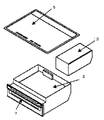
図3は、制御部と電源部からなる機構部3を本体ケースから外に出した図であり、制御部と電源部からなる機構部3の大きな空きスペースができることがわかる。
図1には本体ケースから外に出した制御部と電源部からなる機構部3をコンロ用フロアキャビネット8の配管スペース12に設置している図である。コンロ用フロアキャビネット8には通常、ガス配管などをしまう配管スペース12があり、コンロ用フロアキャビネット8の空きスペースになっているのでそのスペースを収納部として活用する。このとき、機構部3を配管スペースに納めやすいように薄型の金属ケースに納め、コンロ用フロアキャビネット8の壁面に固定することが好ましいが、必ずしもこの限りではない。また、機構部3とIH本体4はハーネスなどのコネクタで接続するのが簡便で使い勝手もよくなるが、機構部3が適切に動作するのであればその他の接続方法を使用してもかまわない。
なお、通常のコンロ用フロアキャビネット8の配管スペース12は奥行きで100mm程度であるが、機構部3の厚さはそれよりも薄い必要があり、さらにできるだけ薄い方が好ましい。大きさもコンロ用フロアキャビネット8の配管スペースに納まれば問題ないが、できるだけ小さい方が好ましい。
また、機構部3には電源コード及び冷却機構が付いていることが好ましい。冷却機構は制御部の温度上昇を防ぐのみでなく、コンロ用フロアキャビネット8内の収納物に影響を与えないように冷却することが好ましい。冷却機構としては放熱フィン及び冷却ファンを用いることが好ましい。機構部3の電源コードを電源プラグ11に接続する。
図3のように、制御部と電源部からなる機構部3を本体ケース4から外に出すことでスペースが空くので、後述するようにグリル庫2を広げ、グリル庫2の使い勝手を向上させることができる。
(Embodiment 1)
FIG. 1 is a schematic vertical sectional side view of kitchen furniture according to the first embodiment of the present invention.
FIG. 2 is a schematic diagram of a conventional IH cooking appliance. In a conventional IH cooking appliance, an
FIG. 3 is a diagram in which the
FIG. 1 is a diagram in which a
In addition, although the piping space 12 of the normal stove floor cabinet 8 is about 100 mm in depth, the thickness of the
Further, the
As shown in FIG. 3, since the
(実施の形態1の変形例1)
図4は電磁式コンロ1と電子レンジ14が一体化した実施形態の図である。本体ケース4から外に出した制御部と電源部からなる機構部3の空きスペースに電子レンジ14の専用制御部を設置することができ、電磁式コンロ1と電子レンジ14の一体化が可能となる。なお、電子レンジ14の加熱、専用制御部13は主として電子レンジの制御部と食品を加熱・調理するマイクロ波を発生させるマグネトロンからなり、マグネトロンは電子レンジ14庫内に近接していることが必要なので、図示していないが、IH調理機器本体ケース4内に電子レンジ14のマグネトロンを設置している。
従来のロースターからなるグリル庫の替わりに電子レンジ14を取り付けることでグリル2庫内の複雑に配置されたヒーターを廃止することができ、従来のロースターからなるグリル庫2に比べ、清掃性を向上させることができる。また、電子レンジ14設置により、ロースターからなるグリル庫2では難しい調理済みの料理の再加熱に電子レンジ14を活用できる。
図4では電磁式コンロ1の制御部と電源部からなる機構部3の空きスペースに電子レンジ14の加熱、専用制御部13を設置しているので本体ケースの中で、電子レンジ14の加熱、専用制御部13がかなりのスペースを占めているが、さらに、電子レンジ14の加熱、専用制御部13をコンパクト化することによって、電子レンジ14庫内の容量を増大させることができ、一度に調理できる量が増え、また、大きなピザなどの食材も調理することが可能となる。
電磁式コンロ1と電子レンジ14が一体化しているものは現状提案されておらず、電磁式コンロ1と電子レンジ14を一体化することで施工の際も取り付けやすくなる。
(
FIG. 4 is a diagram of an embodiment in which the
By installing a
In FIG. 4, since the heating of the
The thing in which the
(実施の形態1の変形例2)
図6は、電磁式コンロ1とオーブン17が一体化した実施形態の図である。前記の実施の形態の変形例1では、電磁式コンロ1と電子レンジ14が一体化した実施形態を示しているが、電子レンジ14よりオーブン17の方が多様な調理ができ、好ましい。
図5に示したように、従来のロースターからなるグリルの替わりにオーブン17を取り付けることでグリル2庫内の複雑に配置されたヒーター15を隠蔽することができ、従来のロースターからなるグリルに比べ、清掃性を向上させることができる。ロースターからなるグリル庫のように庫内中央にヒーターがないため、サザエや焼きいもなど背の高い食材も調理することが可能となる。
図6に示しているように電磁式コンロ1とオーブン17の制御部と電源部からなる機構部3を本体と別体として本体ケース4から外に出し、空きスペースにオーブン17の加熱、専用制御部18を設置することが可能となる。
さらに、オーブン17の加熱、専用制御部18をコンパクト化することによって、オーブン17庫内の容量をUPさせることができ、一度に調理できる量が増え、また、大きなピザなどの食材も調理することが可能となる。
電磁式コンロとオーブン17が一体化しているものは現状提案されておらず、電磁式コンロ1とオーブン17を一体化することで施工の際も取り付けやすくなる。
(
FIG. 6 is a diagram of an embodiment in which the
As shown in FIG. 5, by installing an
As shown in FIG. 6, the
Furthermore, by heating the
The thing which the electromagnetic stove and the
(実施の形態1の変形例3)
図10は、電磁式コンロ1とオーブンレンジ21が一体化した実施形態の図である。すなわち、電磁式コンロ1とオーブンレンジ21の制御部と電源部からなる機構部3を本体と別体として本体ケース4から外に出し、空きスペースにオーブンレンジ加熱、専用制御部22を設置したものである。オーブンレンジ加熱、専用制御部22は主として尾0−分レンジ21の制御部とヒーター、食品を加熱・調理するマイクロ波を発生させるマグネトロンからなり、ヒーター、マグネトロンはオーブンレンジ21庫内に近接していることが必要なので、図10のようにIH調理機器本体ケース4内にオーブンレンジ21の加熱、専用制御部を設置している。
上記実施の形態1、2に記載の利点に加え、オーブンによる多様な調理と電子レンジによる調理済み食材の再加熱を一台で行えるという利点が備わってる。
(
FIG. 10 is a diagram of an embodiment in which the
In addition to the advantages described in the first and second embodiments, there is an advantage that various cooking using an oven and reheating of cooked food using a microwave oven can be performed in one unit.
(実施の形態2)
図7は、本発明の実施の形態2における図である。
背の高く大きな食材を調理するにはグリル本体ケース4の幅の制約から、調理機器容積の中で電子レンジ14、または電子レンジまたはオーブン2、またはオーブン17庫内が占める容積を80%以上にすることが必要である。しかしながら、現状のグリル2では制御部、電源部の機構部があるため、調理機器容積の中での電子レンジ14またはオーブン17、オーブンレンジ21からなるグリル庫内が占める容積を70%以上にすることは不可能である。そこで、前記電磁式コンロ1と電子レンジ14またはオーブン17、オーブンレンジ21の制御部と電源部からなる機構部3を別体として、コンロ用フロアキャビネット8の配管スペース12に備えることで、電子レンジ14やオーブン17、オーブンレンジ21の加熱部、専用制御部を本体ケース4内に設置しても調理機器容積の中で電子レンジ14またはオーブン17、オーブンレンジ21からなるグリル庫内が占める容積を80%以上にすることは可能である。
前記のように制御部と電源部からなる機構部3を別体として、コンロ用フロアキャビネット8の配管スペース12に備えることで、図7のようにグリル庫2を本体ケース4の幅いっぱいに設計できるようになる。これにより、魚料理などの場合一度に調理できる量が増え、また、大きなピザなどの食材も調理することが可能となる。
(Embodiment 2)
FIG. 7 is a diagram according to the second embodiment of the present invention.
To cook tall and large foods, due to the limitation of the width of the
As described above, the
(実施の形態3)
図8は、前記の実施の形態1の各変形例、実施の形態2の電子レンジ14またはオーブン17、オーブンレンジ21からなるグリル庫内表面にガラスコーティング19が施されていることを示した図である。ガラスコーティング19を施すことによって、庫内に付着した汚れを比較的簡単に除去でき、お手入れがさらに楽になる。
ガラスコーティング19として、前記のホーローでの被覆や、ガラスコーティング、セラミックコーティングなど無機系コーティング材で被覆してもよい。被覆方法は例えばディッピング法、スピンコート法、スプレー法、印刷法、フローコート法、ロールコート法並びにこれらの併用等、既知の塗布手段を適宜採用することができる。焼成温度はホーローの場合、500〜900℃が好ましいが、ガラスコーティング、セラミックコーティングなど無機系コーティング材ではもっと低温(300℃〜常温)で乾燥させることも可能である。
(Embodiment 3)
FIG. 8 is a view showing that the
The
(実施の形態4)
図9は、前記の実施の形態1の各変形例の電子レンジ14またはオーブン17、オーブンレンジ21からなるグリル庫内表面にジルコニアコーティング20が施されていることを示した図である。ジルコニアコーティング20は魚焼きなどによる焦げ付き抑制に優れており、庫内に汚れの固着するのを防ぎ、さらに、お手入れが楽になる。ジルコニアコーティング20としては、酸化ジルコニウムを含むホーローコーティングを施す方法がある。ただし、焼成温度はアルカリ酸化物量を多くしても500℃以上は必要である。他に、酸化ジルコニウム粒子を含むコーティングを施す方法がある。グリル庫内温度は特に電子レンジまたはオーブンの場合には250℃以上に達するため、有機系コーティング剤では耐熱性が不充分なため、耐熱性に優れた無機系コーティング剤の使用が好ましい。酸化ジルコニウム粒子を含む無機系コーティングの乾燥温度は比較的低温(300℃〜常温)で乾燥・硬化させることが可能である。
ジルコニアコーティング20の被覆方法は例えばディッピング法、スピンコート法、スプレー法、印刷法、フローコート法、ロールコート法並びにこれらの併用等、既知の塗布手段を適宜採用することができる。
(Embodiment 4)
FIG. 9 is a diagram showing that the
As the coating method of the
以上のように、本発明にかかる厨房家具は、電磁式コンロと電子レンジまたはオーブンのうち少なくとも一つの加熱部と機構部を別体として、機構部を収納部に備え、従来のグリル庫内の複雑に配置されたヒーターをなくし、庫内容量UPし、さらに、庫内をガラスコーティングまたはジルコニアコーティングすることで表面平滑性が向上し、油汚れのこびりつきも抑制できることで、調理機器の清掃性及び使い勝手を向上させることができるもので、家庭用、業務用の調理機器等の用途に広く適用できる。 As described above, the kitchen furniture according to the present invention includes at least one heating unit and a mechanism unit in an electromagnetic stove and a microwave oven or an oven, and includes a mechanism unit in a storage unit. Eliminating heaters arranged in a complicated manner, increasing the storage capacity, and further improving the surface smoothness by applying glass coating or zirconia coating to the interior of the storage. Usability can be improved and it can be widely applied to household and commercial cooking appliances.
1…IHヒーター
2…グリル庫
3…機構(制御、電源)部
4…IH本体ケース
5…トッププレート
6…前面パネル
7…グリルドア
8…コンロ用フロアキャビネット
9…キッチンカウンター
10…ハーネス(コネクタ接続)
11…電源プラグ
12…配管スペース
13…電子レンジ加熱、専用制御部
14…電子レンジ
15…オーブンのヒーター
16…グリル焼き網
17…オーブン
18…オーブン加熱、専用制御部
19…ガラスコーティング
20…ジルコニアコーティング
21…オーブンレンジ
22…オーブンレンジ加熱、専用制御部
DESCRIPTION OF
DESCRIPTION OF SYMBOLS 11 ... Power plug 12 ... Piping space 13 ... Microwave oven heating,
Claims (5)
グリル庫と、備え、
前記グリル庫には電子レンジまたはオーブンのうちの少なくとも一つが設けられている調理器具と、
前記調理器具が載置されるキャビネットを備えた厨房家具において、
前記キャビネット内部に収納部を備え、
前記電磁調理器は加熱部と機構部を備え、
前記機構部を前記収納部内に設置したことを特徴とする厨房家具。 An electromagnetic cooker,
With a grill,
A cooking utensil provided with at least one of a microwave oven or an oven in the grill;
In kitchen furniture provided with a cabinet on which the cooking utensils are placed,
A storage section is provided inside the cabinet,
The electromagnetic cooker includes a heating unit and a mechanism unit,
Kitchen furniture, wherein the mechanism section is installed in the storage section.
Priority Applications (1)
| Application Number | Priority Date | Filing Date | Title |
|---|---|---|---|
| JP2008323082A JP5605738B2 (en) | 2008-12-19 | 2008-12-19 | Kitchen furniture |
Applications Claiming Priority (1)
| Application Number | Priority Date | Filing Date | Title |
|---|---|---|---|
| JP2008323082A JP5605738B2 (en) | 2008-12-19 | 2008-12-19 | Kitchen furniture |
Publications (2)
| Publication Number | Publication Date |
|---|---|
| JP2010142437A true JP2010142437A (en) | 2010-07-01 |
| JP5605738B2 JP5605738B2 (en) | 2014-10-15 |
Family
ID=42563478
Family Applications (1)
| Application Number | Title | Priority Date | Filing Date |
|---|---|---|---|
| JP2008323082A Expired - Fee Related JP5605738B2 (en) | 2008-12-19 | 2008-12-19 | Kitchen furniture |
Country Status (1)
| Country | Link |
|---|---|
| JP (1) | JP5605738B2 (en) |
Cited By (3)
| Publication number | Priority date | Publication date | Assignee | Title |
|---|---|---|---|---|
| JP2021014968A (en) * | 2019-07-16 | 2021-02-12 | 三菱電機株式会社 | Cooker |
| JP2022051855A (en) * | 2018-11-15 | 2022-04-01 | 三菱電機株式会社 | Built-in combined cooking equipment and kitchen furniture |
| JP2022051856A (en) * | 2018-11-15 | 2022-04-01 | 三菱電機株式会社 | Built-in composite cooker and kitchen furniture |
Families Citing this family (1)
| Publication number | Priority date | Publication date | Assignee | Title |
|---|---|---|---|---|
| CN111174263B (en) * | 2020-04-01 | 2021-07-27 | 韩波 | Integrated kitchen range without oil smoke emission |
Citations (5)
| Publication number | Priority date | Publication date | Assignee | Title |
|---|---|---|---|---|
| JPS5344347U (en) * | 1976-09-21 | 1978-04-15 | ||
| JP2001258746A (en) * | 2000-03-21 | 2001-09-25 | Sharp Corp | Cooking surface structure of cooking equipment for high temperature heating and method of manufacturing the same |
| JP2004218901A (en) * | 2003-01-14 | 2004-08-05 | Matsushita Electric Ind Co Ltd | Cooking device |
| JP2007020697A (en) * | 2005-07-13 | 2007-02-01 | Cleanup Corp | Kitchen furniture |
| JP2007330454A (en) * | 2006-06-14 | 2007-12-27 | Cleanup Corp | System kitchen |
-
2008
- 2008-12-19 JP JP2008323082A patent/JP5605738B2/en not_active Expired - Fee Related
Patent Citations (5)
| Publication number | Priority date | Publication date | Assignee | Title |
|---|---|---|---|---|
| JPS5344347U (en) * | 1976-09-21 | 1978-04-15 | ||
| JP2001258746A (en) * | 2000-03-21 | 2001-09-25 | Sharp Corp | Cooking surface structure of cooking equipment for high temperature heating and method of manufacturing the same |
| JP2004218901A (en) * | 2003-01-14 | 2004-08-05 | Matsushita Electric Ind Co Ltd | Cooking device |
| JP2007020697A (en) * | 2005-07-13 | 2007-02-01 | Cleanup Corp | Kitchen furniture |
| JP2007330454A (en) * | 2006-06-14 | 2007-12-27 | Cleanup Corp | System kitchen |
Cited By (5)
| Publication number | Priority date | Publication date | Assignee | Title |
|---|---|---|---|---|
| JP2022051855A (en) * | 2018-11-15 | 2022-04-01 | 三菱電機株式会社 | Built-in combined cooking equipment and kitchen furniture |
| JP2022051856A (en) * | 2018-11-15 | 2022-04-01 | 三菱電機株式会社 | Built-in composite cooker and kitchen furniture |
| JP7292449B2 (en) | 2018-11-15 | 2023-06-16 | 三菱電機株式会社 | Built-in compound type heating cooker and kitchen furniture |
| JP7292450B2 (en) | 2018-11-15 | 2023-06-16 | 三菱電機株式会社 | Built-in compound type heating cooker and kitchen furniture |
| JP2021014968A (en) * | 2019-07-16 | 2021-02-12 | 三菱電機株式会社 | Cooker |
Also Published As
| Publication number | Publication date |
|---|---|
| JP5605738B2 (en) | 2014-10-15 |
Similar Documents
| Publication | Publication Date | Title |
|---|---|---|
| JP5820977B2 (en) | Cooker | |
| JP5316157B2 (en) | Cooker | |
| US2526476A (en) | Apartment range | |
| JP5605738B2 (en) | Kitchen furniture | |
| CN209528930U (en) | Cooking utensil with slightly roast function | |
| JP5909673B2 (en) | Cooker | |
| JP5786131B2 (en) | Cooker | |
| JP5877298B2 (en) | Cooker | |
| CN108464650A (en) | Multifunctional mobile kitchen | |
| JP5477761B2 (en) | Kitchen furniture | |
| CN204797635U (en) | Roaster | |
| JP2012021693A (en) | Heating cooker | |
| JP2009041819A (en) | Steam cooker | |
| CN202537264U (en) | A household electric oven | |
| CN102613912A (en) | Domestic electric oven | |
| JP4108111B2 (en) | Cooktop | |
| KR100439324B1 (en) | Heating cooker | |
| KR200479718Y1 (en) | Multipurpose grill and grill device using the same | |
| CN218237545U (en) | Function machine and integrated kitchen | |
| CN219895425U (en) | oven | |
| JP2011098139A (en) | Cooker | |
| JP5486648B2 (en) | Steam cooker | |
| WO2010138135A1 (en) | Indoor grill grid apparatus | |
| JP2009041818A (en) | Steam cooker | |
| JP4110104B2 (en) | Induction heating cooker |
Legal Events
| Date | Code | Title | Description |
|---|---|---|---|
| A621 | Written request for application examination |
Free format text: JAPANESE INTERMEDIATE CODE: A621 Effective date: 20111128 |
|
| A977 | Report on retrieval |
Free format text: JAPANESE INTERMEDIATE CODE: A971007 Effective date: 20130218 |
|
| A131 | Notification of reasons for refusal |
Free format text: JAPANESE INTERMEDIATE CODE: A131 Effective date: 20130225 |
|
| A521 | Request for written amendment filed |
Free format text: JAPANESE INTERMEDIATE CODE: A523 Effective date: 20130423 |
|
| A131 | Notification of reasons for refusal |
Free format text: JAPANESE INTERMEDIATE CODE: A131 Effective date: 20140120 |
|
| A521 | Request for written amendment filed |
Free format text: JAPANESE INTERMEDIATE CODE: A523 Effective date: 20140131 |
|
| TRDD | Decision of grant or rejection written | ||
| A01 | Written decision to grant a patent or to grant a registration (utility model) |
Free format text: JAPANESE INTERMEDIATE CODE: A01 Effective date: 20140804 |
|
| R150 | Certificate of patent or registration of utility model |
Ref document number: 5605738 Country of ref document: JP Free format text: JAPANESE INTERMEDIATE CODE: R150 |
|
| A61 | First payment of annual fees (during grant procedure) |
Free format text: JAPANESE INTERMEDIATE CODE: A61 Effective date: 20140817 |
|
| LAPS | Cancellation because of no payment of annual fees |