JP2010142370A - Electronic sphygmomanometer - Google Patents
Electronic sphygmomanometer Download PDFInfo
- Publication number
- JP2010142370A JP2010142370A JP2008321470A JP2008321470A JP2010142370A JP 2010142370 A JP2010142370 A JP 2010142370A JP 2008321470 A JP2008321470 A JP 2008321470A JP 2008321470 A JP2008321470 A JP 2008321470A JP 2010142370 A JP2010142370 A JP 2010142370A
- Authority
- JP
- Japan
- Prior art keywords
- pressure
- cuff
- pressure control
- value
- measurement
- Prior art date
- Legal status (The legal status is an assumption and is not a legal conclusion. Google has not performed a legal analysis and makes no representation as to the accuracy of the status listed.)
- Granted
Links
Images


Classifications
-
- A—HUMAN NECESSITIES
- A61—MEDICAL OR VETERINARY SCIENCE; HYGIENE
- A61B—DIAGNOSIS; SURGERY; IDENTIFICATION
- A61B5/00—Measuring for diagnostic purposes; Identification of persons
- A61B5/02—Detecting, measuring or recording for evaluating the cardiovascular system, e.g. pulse, heart rate, blood pressure or blood flow
- A61B5/021—Measuring pressure in heart or blood vessels
- A61B5/022—Measuring pressure in heart or blood vessels by applying pressure to close blood vessels, e.g. against the skin; Ophthalmodynamometers
- A61B5/02233—Occluders specially adapted therefor
-
- A—HUMAN NECESSITIES
- A61—MEDICAL OR VETERINARY SCIENCE; HYGIENE
- A61B—DIAGNOSIS; SURGERY; IDENTIFICATION
- A61B2560/00—Constructional details of operational features of apparatus; Accessories for medical measuring apparatus
- A61B2560/02—Operational features
- A61B2560/0242—Operational features adapted to measure environmental factors, e.g. temperature, pollution
- A61B2560/0247—Operational features adapted to measure environmental factors, e.g. temperature, pollution for compensation or correction of the measured physiological value
- A61B2560/0261—Operational features adapted to measure environmental factors, e.g. temperature, pollution for compensation or correction of the measured physiological value using hydrostatic pressure
-
- A—HUMAN NECESSITIES
- A61—MEDICAL OR VETERINARY SCIENCE; HYGIENE
- A61B—DIAGNOSIS; SURGERY; IDENTIFICATION
- A61B5/00—Measuring for diagnostic purposes; Identification of persons
- A61B5/02—Detecting, measuring or recording for evaluating the cardiovascular system, e.g. pulse, heart rate, blood pressure or blood flow
- A61B5/021—Measuring pressure in heart or blood vessels
- A61B5/022—Measuring pressure in heart or blood vessels by applying pressure to close blood vessels, e.g. against the skin; Ophthalmodynamometers
- A61B5/02225—Measuring pressure in heart or blood vessels by applying pressure to close blood vessels, e.g. against the skin; Ophthalmodynamometers using the oscillometric method
-
- A—HUMAN NECESSITIES
- A61—MEDICAL OR VETERINARY SCIENCE; HYGIENE
- A61B—DIAGNOSIS; SURGERY; IDENTIFICATION
- A61B5/00—Measuring for diagnostic purposes; Identification of persons
- A61B5/02—Detecting, measuring or recording for evaluating the cardiovascular system, e.g. pulse, heart rate, blood pressure or blood flow
- A61B5/021—Measuring pressure in heart or blood vessels
- A61B5/022—Measuring pressure in heart or blood vessels by applying pressure to close blood vessels, e.g. against the skin; Ophthalmodynamometers
- A61B5/0225—Measuring pressure in heart or blood vessels by applying pressure to close blood vessels, e.g. against the skin; Ophthalmodynamometers the pressure being controlled by electric signals, e.g. derived from Korotkoff sounds
Landscapes
- Health & Medical Sciences (AREA)
- Life Sciences & Earth Sciences (AREA)
- Cardiology (AREA)
- Vascular Medicine (AREA)
- Engineering & Computer Science (AREA)
- Medical Informatics (AREA)
- Physics & Mathematics (AREA)
- Ophthalmology & Optometry (AREA)
- Biophysics (AREA)
- Pathology (AREA)
- Dentistry (AREA)
- Biomedical Technology (AREA)
- Heart & Thoracic Surgery (AREA)
- Physiology (AREA)
- Molecular Biology (AREA)
- Surgery (AREA)
- Animal Behavior & Ethology (AREA)
- General Health & Medical Sciences (AREA)
- Public Health (AREA)
- Veterinary Medicine (AREA)
- Measuring Pulse, Heart Rate, Blood Pressure Or Blood Flow (AREA)
Abstract
Description
本発明は、電子血圧計に関し、特に、角度センサを備えた電子血圧計に関する。 The present invention relates to an electronic sphygmomanometer, and more particularly to an electronic sphygmomanometer including an angle sensor.
上腕、手首、指の動脈圧情報により血圧を測定する電子血圧計が普及している。測定部位の高さが心臓位置より高ければ血圧値は低く、心臓位置より低ければ血圧値は高い傾向に判定される。そのため、測定部位の高さと心臓の高さとを一致させて血圧を測定する必要がある。測定部位の高さと心臓の高さとの不一致は、毎日の血圧値変化を管理する上での大きな変動要因であった。 Electronic sphygmomanometers that measure blood pressure based on arterial pressure information of the upper arm, wrist, and finger are widely used. If the height of the measurement site is higher than the heart position, the blood pressure value is determined to be low, and if it is lower than the heart position, the blood pressure value is determined to be high. Therefore, it is necessary to measure the blood pressure by matching the height of the measurement site with the height of the heart. The discrepancy between the height of the measurement site and the height of the heart was a major fluctuation factor in managing daily blood pressure changes.
そのため、従来より、測定部位の高さと心臓の高さとを一致させて血圧を測定するための提案がなされている(特許文献1〜3)。たとえば特許文献1には、測定部位が手首の電子血圧計において、前腕の角度検出手段に加えて上腕に角度検出手段を設け、前腕と上腕の検出角度に基づいてカフの位置と心臓の位置との高低差が算出されることが開示されている。また、2軸の角度検出手段により前腕のピッチ方向およびロール方向の角度が検出され、これらの検出値に基づいてカフの位置と心臓の位置との高低差が算出されることも開示されている。
上記のような従来技術では、カフの位置と心臓の位置との高低差を算出することで正しい測定姿勢に導くことは可能である。しかし、血圧測定中に姿勢がくずれた(両者の高低差が所定範囲を超えた)場合には、圧脈波が乱れることにより、測定精度を保ちながら継続して測定を続けることはできない。したがって、そのような場合には、測定精度を保つために、測定を始めからやり直さなければならなかった。 In the conventional technique as described above, it is possible to lead to a correct measurement posture by calculating a difference in height between the position of the cuff and the position of the heart. However, when the posture is deformed during blood pressure measurement (the difference in height between the two exceeds a predetermined range), the pressure pulse wave is disturbed, so that measurement cannot be continued while maintaining measurement accuracy. Therefore, in such a case, in order to maintain the measurement accuracy, the measurement has to be performed again from the beginning.
本発明は、上記のような問題を解決するためになされたものであって、その目的は、測定途中に測定部位の位置(高さ)と心臓の位置(高さ)とがずれたとしても測定を続けることができ、かつ、測定精度を保つことのできる電子血圧計を提供することである。 The present invention has been made in order to solve the above-described problems. The purpose of the present invention is that even if the position (height) of the measurement site and the position (height) of the heart are shifted during measurement. An object is to provide an electronic sphygmomanometer capable of continuing measurement and maintaining measurement accuracy.
この発明のある局面に従う電子血圧計は、被測定者の所定の測定部位に巻き付けるためのカフと、所定の基準方向に対するカフの角度を検出するための角度検出手段と、カフ内の圧力を表わすカフ圧信号を検出するための圧力検出手段と、カフ内の圧力を特定方向に変化させるための第1の圧力制御を行ない、かつ、第1の圧力制御の際にカフ圧信号を取得することにより圧脈波を測定するための圧力制御手段と、第1の圧力制御が実行されている際に、角度検出手段からの出力に基づいて、カフの位置と仮想的な心臓位置との位置ずれが発生したか否かを判断するための判断手段と、判断手段により位置ずれが発生したと判断された場合に、第1の圧力制御を停止し、特定方向とは逆方向にカフ内の圧力を変化させるための第2の圧力制御を行なうことにより、カフ内の圧力を、位置ずれが発生する前の圧力値を表わす特定圧力値まで戻すための戻り処理手段とを備え、圧力制御手段は、戻り処理手段による処理の後に、第1の圧力制御を再開する。 An electronic sphygmomanometer according to an aspect of the present invention represents a cuff for wrapping around a predetermined measurement site of a person to be measured, an angle detection means for detecting an angle of the cuff with respect to a predetermined reference direction, and a pressure in the cuff. Performing pressure detection means for detecting the cuff pressure signal and first pressure control for changing the pressure in the cuff in a specific direction, and obtaining the cuff pressure signal at the time of the first pressure control; When the first pressure control is being executed and the pressure control means for measuring the pressure pulse wave by the position difference between the cuff position and the virtual heart position based on the output from the angle detection means The first pressure control is stopped when it is determined by the determination means that the positional deviation has occurred, and the pressure in the cuff is opposite to the specific direction. Second pressure control for changing And a return processing means for returning the pressure in the cuff to a specific pressure value representing a pressure value before the occurrence of the positional deviation, and the pressure control means includes a first processing means after the processing by the return processing means. Resume pressure control.
好ましくは、位置ずれが発生する前に測定された圧脈波の振幅と、圧力制御が再開された後の圧脈波の振幅とに基づいて、血圧値を算出するための算出手段をさらに備える。 Preferably, the apparatus further includes a calculation unit for calculating a blood pressure value based on the amplitude of the pressure pulse wave measured before the occurrence of the positional deviation and the amplitude of the pressure pulse wave after the pressure control is resumed. .
好ましくは、戻り処理手段は、角度検出手段からの出力に基づいて、被測定者に対し、カフの位置を補正するためのガイドを行なう。 Preferably, the return processing means performs a guide for correcting the position of the cuff for the person to be measured based on the output from the angle detection means.
好ましくは、表示手段をさらに備え、戻り処理手段は、角度検出手段からの出力に基づいて、カフの位置と心臓位置との位置関係を示す情報を表示手段に表示するための処理を行なう。 Preferably, a display means is further provided, and the return processing means performs a process for displaying information indicating the positional relationship between the cuff position and the heart position on the display means based on the output from the angle detection means.
好ましくは、圧力制御手段は、戻り処理手段による処理の結果、カフの位置と心臓位置とが所定範囲内に収まったことを検知した場合に、第1の圧力制御を再開する。 Preferably, the pressure control means resumes the first pressure control when it is detected that the position of the cuff and the heart position are within a predetermined range as a result of the processing by the return processing means.
好ましくは、圧力制御手段は、戻り処理手段による処理の結果、カフの位置と心臓位置とが所定範囲内に収まったことを検知し、かつ、波形が安定したことを検知した場合に、第1の圧力制御を再開する。 Preferably, when the pressure control unit detects that the position of the cuff and the heart position are within a predetermined range as a result of the processing by the return processing unit, and detects that the waveform is stable, the first control unit Resume pressure control.
好ましくは、測定開始前に、角度検出手段からの出力に基づいて、カフの位置と心臓位置との関係を報知するための報知処理手段をさらに備え、圧力制御手段は、カフの位置と心臓位置とが所定範囲内に収まったことを検知した場合に、第1の圧力制御を開始する。 Preferably, prior to the start of measurement, the information processing means for notifying the relationship between the cuff position and the heart position based on the output from the angle detection means is further provided, and the pressure control means includes the cuff position and the heart position. Is detected within the predetermined range, the first pressure control is started.
好ましくは、特定圧力値は、第1の圧力制御を停止した時点の圧力値から所定値差し引いた値である。 Preferably, the specific pressure value is a value obtained by subtracting a predetermined value from the pressure value at the time when the first pressure control is stopped.
好ましくは、特定圧力値は、位置ずれが発生した時点の圧力値から所定値差し引いた値である。 Preferably, the specific pressure value is a value obtained by subtracting a predetermined value from the pressure value at the time when the positional deviation occurs.
本発明によると、測定途中にカフの位置と心臓位置とがずれたとしても測定を続けることができる。また、位置ずれが発生する前の圧力値までカフ内の圧力を戻してから第1の圧力制御を再開するので、測定精度を高く維持することができる。 According to the present invention, even if the position of the cuff and the heart position are shifted during measurement, the measurement can be continued. In addition, since the first pressure control is resumed after the pressure in the cuff is returned to the pressure value before the positional deviation occurs, the measurement accuracy can be maintained high.
本発明の実施の形態について図面を参照しながら詳細に説明する。なお、図中同一または相当部分には同一符号を付してその説明は繰返さない。 Embodiments of the present invention will be described in detail with reference to the drawings. In the drawings, the same or corresponding parts are denoted by the same reference numerals and description thereof will not be repeated.
<外観および構成について>
はじめに、本発明の実施の形態に係る電子血圧計(以下「血圧計」という)1の外観および構成について説明する。
<Appearance and configuration>
First, the appearance and configuration of an electronic blood pressure monitor (hereinafter referred to as “blood pressure monitor”) 1 according to an embodiment of the present invention will be described.
(外観について)
図1は、本発明の実施の形態に係る血圧計1の外観斜視図である。
(About appearance)
FIG. 1 is an external perspective view of a
図1を参照して、血圧計1は、本体部10と、被測定者の手首に巻き付け可能なカフ20とを備える。本体部10はカフ20に取り付けられている。本体部10の表面には、たとえば液晶等により構成される表示部40と、ユーザ(代表的に被測定者)からの指示を受付けるための操作部41とが配置されている。操作部41は、たとえば複数のスイッチを含む。
Referring to FIG. 1, a
(ハードウェア構成について)
図2は、本発明の実施の形態に係る血圧計1のハードウェア構成を表わすブロック図である。
(About hardware configuration)
FIG. 2 is a block diagram showing a hardware configuration of
図2を参照して、血圧計1のカフ20は、空気袋21を含む。空気袋21は、エアチューブ31を介して、エア系30に接続される。
Referring to FIG. 2,
本体部10は、上述の表示部40および操作部41に加え、エア系30と、各部を集中的に制御し、各種演算処理を行なうためのCPU(Central Processing Unit)100と、CPU100に所定の動作をさせるプログラムや各種データを記憶するためのメモリ部42と、測定された血圧値を記憶するための不揮発性メモリ(たとえばフラッシュメモリ)43と、CPU100に電力を供給するための電源44と、計時動作を行なう計時部45と、外部よりデータの入力を受付けるためのデータ入出力部46と、所定の基準方向に対する、(カフ20に取り付けられた)本体部10の角度を検出するための角度センサ60と、角度センサ60からのアナログ信号をデジタル信号に変換するためのA/D(analog to digital)コンバータ61と、警告音等を発するためのブザー62とを含む。
In addition to the
操作部41は、電源をONまたはOFFするための指示の入力を受付ける電源スイッチ41Aと、測定開始の指示を受付けるための測定スイッチ41Bと、測定停止の指示を受付けるための停止スイッチ41Cと、フラッシュメモリ43に記録された血圧などの情報を読み出す指示を受付けるためのメモリスイッチ41Dとを有する。なお、操作部41は、被測定者を識別するためのID(Identification)情報を入力するために操作されるIDスイッチ(図示せず)をさらに有してもよい。これにより、被測定者ごとに測定データの記録および読出しをすることができる。
The
エア系30は、空気袋21内の圧力(カフ圧)を検出するための圧力センサ32と、カフ圧を加圧するために、空気袋21に空気を供給するためのポンプ51と、空気袋21の空気を排出しまたは封入するために開閉される弁52とを含む。
The
本体部10は、上記エア系30に関連して、発振回路33と、ポンプ駆動回路53と、弁駆動回路54とをさらに含む。
The
圧力センサ32は、静電容量形の圧力センサであり、カフ圧により容量値が変化する。なお、圧力センサ32は、静電容量式に限定されず、たとえばピエゾ抵抗式であってもよい。発振回路33は、圧力センサ32の容量値に応じた発振周波数の信号をCPU100に出力する。CPU100は、発振回路33から得られる信号を圧力に変換し圧力を検知する。ポンプ駆動回路53は、ポンプ51の駆動をCPU100から与えられる制御信号に基づいて制御する。弁駆動回路54は弁52の開閉制御をCPU100から与えられる制御信号に基づいて行なう。
The
ポンプ51、弁52、ポンプ駆動回路53および弁駆動回路54は、カフ圧を調整するための調整機構50を構成する。なお、カフ圧を調整するためのデバイスは、これらに限定されるものではない。
The
データ入出力部46は、たとえば、着脱可能な記録媒体132からプログラムやデータの読み出しおよび書き込みをする。また/あるいは、データ入出力部46は、外部の図示しないコンピュータから通信回線を介してプログラムやデータの送受信ができてもよい。
The data input /
角度センサ60は、たとえば2軸の角度センサであり、ピッチ方向の重力加速度センサ601と、ロール方向の重力加速度センサ602とを含む。この場合、角度検出の基準となる「基準方向」は、たとえば鉛直方向である。
The
A/Dコンバータ61は、2つの重力加速度センサ601,602より信号を入力し、それぞれの信号をデジタル信号に変換する。そして、変換したデジタル信号を、独立にCPU100に与える。これにより、CPU100は、測定部位である手首と仮想的な心臓位置とのずれ幅(代表的に高低差)を算出することができる。
The A /
なお、角度センサ60は、手首に巻き付けられたカフ20の角度を検出することができれば、このような2軸の角度センサでなくてもよく、1軸の角度センサであってもよい。または、特許文献1に記載のように、本体部10だけでなく、別途上腕にも角度センサを設けてもよい。
The
また、本実施の形態における血圧計1は、図1に示されるように、本体部10がカフ20に取り付けられた形態であることとするが、上腕式の血圧計で採用されているような、本体部10とカフ20とがエアチューブ(図2においてエアチューブ31)によって接続される形態のものであってもよい。その場合、本体部10ではなくカフ20に、角度センサ60が設置されればよい。
In addition, as shown in FIG. 1, the
なお、カフ20には空気袋21が含まれることとしたが、カフ20に供給される流体は空気に限定されるものではなく、たとえば液体やゲルであってもよい。あるいは、流体に限定されるものではなく、マイクロビーズなどの均一な微粒子であってもよい。
Although the
また、本実施の形態では、所定の測定部位が手首であることとするが、限定的ではなく、上腕など他の部位であってもよい。 In the present embodiment, the predetermined measurement site is the wrist, but is not limited, and may be another site such as the upper arm.
(機能構成について)
図3は、本発明の実施の形態に係る血圧計1の機能構成を示す機能ブロック図である。なお、図3には、加圧測定方式すなわち、加圧の際に得られた圧力値に基づいて、血圧値を算出する方式の機能構成が示されている。
(About functional configuration)
FIG. 3 is a functional block diagram showing a functional configuration of the
図3を参照して、CPU100は、その機能として、ずれ算出部101と、報知処理部102と、加圧制御部104と、戻り処理部106と、血圧算出部108と、出力処理部110とを含む。加圧制御部104は、ずれ判断部112を有する。なお、図3には、説明を簡単にするために、CPU100の有する各機能部との間で直接的に信号を授受する周辺のハードウェアのみ示されている。
Referring to FIG. 3,
ずれ算出部101は、A/Dコンバータ61より入力された、2つの重力加速度センサ601,602の検出信号に基づいて、手首の高さと仮想的な心臓の高さとの相対的なずれ幅を算出する。具体的には、まず、A/Dコンバータ61より入力される2つの検出信号に基づいて手首のピッチ方向の角度およびロール方向の角度を算出する。そして、算出された角度から心臓と血圧計1の所定の基準位置との高低差(すなわちずれ幅)を算出する。本実施の形態では、特許文献1に記載された手法でずれ幅を算出することとしたが、このような手法に限定されず、公知の手法で実現可能である。ずれ算出部101は、算出したずれ幅の情報を、報知処理部102、加圧制御部104のずれ判断部112、および戻り処理部106に出力する。
The
報知処理部102は、測定開始前に、被測定者の測定姿勢を正しい姿勢に導くために、入力されたずれ幅の情報に基づいて、手首の位置と心臓の位置との関係を報知する処理を行なう。具体的には、たとえば、入力されたずれ幅の情報を表示部40に表示したり、ブザー62にて警告音を発生させる。
The
加圧制御部104は、カフ20内の圧力を特定方向すなわち上昇方向に変化させるための制御を行なう。つまり、ポンプ51を駆動させることでカフ20の加圧制御を行なう。また、加圧制御部104は、加圧制御の際に、発振回路33からの信号を入力し、圧脈波を測定する。本実施の形態では、加圧制御部104は、加圧制御の際に圧脈波の振幅も算出する。
The
加圧制御部104の処理と並行して、判断部112は、ずれ算出部101より入力されるずれ幅の情報に基づいて、手首の高さと心臓の高さとが所定値以上ずれたか否か、つまり、手首の位置と心臓位置との位置ずれが発生したか否かを判断する。
In parallel with the processing of the
戻り処理部106は、ずれ判断部112により位置ずれが発生したと判断された場合に、加圧制御を停止し、位置ずれが発生する前の特定圧力値まで減圧する処理を行なう。「特定圧力値」は、たとえば、加圧制御が停止された時点の圧力値から所定値(たとえば8mmHg)差し引いた値、または、位置ずれが発生した時点の圧力値から所定値(たとえば5mmHg)差し引いた値である。上記2つの所定値は、いずれも、位置ずれが発生した時点から1〜3拍の時間(成人の標準的な時間)に相当する分、戻るような値であることが好ましい。このような所定値は、たとえば出荷時に、加圧制御の速度に依存して定められてよい。なお、加圧速度が状況や条件等によって変更可能であるような場合には、所定値に限定されず、位置ずれが発生した時点から1〜3拍の時間(成人の標準的な時間)に相当する分、戻すための圧力値を算出してもよい。
When the
戻り処理部106により一部の圧力区間逆方向の圧力制御が行なわれると、再び加圧制御部104による加圧制御が実行される。
When the pressure control in the reverse direction of a part of the pressure sections is performed by the
血圧算出部108は、加圧制御部104により加圧制御中に算出された圧脈波の振幅に基づいて、血圧値、たとえば最高血圧および最低血圧を算出する。測定期間中、戻り処理部106による処理が実行されると、血圧算出部108は、位置ずれが発生する前に測定された圧脈波の振幅と、加圧制御が再開された後の圧脈波の振幅とに基づいて、血圧値を算出する。算出した血圧値の情報は、出力処理部110に出力される。
The blood
出力処理部110は、入力した血圧値の情報を出力する処理を行なう。具体的には、たとえば、表示部40に血圧値を表示する。また、フラッシュメモリ43に測定の際の日時と対応付けて血圧値を記憶してもよい。
The
なお、上述の各機能ブロックの動作は、メモリ部42中に格納されたソフトウェアを実行することで実現されてもよいし、これらの機能ブロックのうち少なくとも1つについては、ハードウェアで実現されてもよい。
The operation of each functional block described above may be realized by executing software stored in the
<動作について>
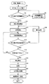
図4は、本発明の実施の形態における血圧計1が実行する血圧測定処理を示すフローチャートである。図4のフローチャートに示す処理は、予めプログラムとしてメモリ部42に格納されており、CPU100がこのプログラムを読み出して実行することにより、血圧測定処理の機能が実現される。
<About operation>
FIG. 4 is a flowchart showing blood pressure measurement processing executed by
なお、この処理は、電源がオンされた後、測定スイッチ41Bが押下された場合に開始されてよい。測定スイッチ41Bが押下されると、ずれ算出部101によるずれ幅の算出処理が別ルーチンで実行されており、算出されたずれ幅の情報が、たとえばメモリ部42の所定の領域に上書き記録されていると仮定する。
This process may be started when the
図4を参照して、はじめに、CPU100は、ゼロセッティングすなわち初期リセットを完了する(ステップS2)。具体的には、メモリ部42の所定の領域を初期化し、空気袋21の空気を排気し、圧力センサ32の0mmHg補正を行なう。
Referring to FIG. 4, first,
次に、報知処理部102が、ずれ算出部101が算出したずれ幅が所定範囲内か否かを判断する(ステップS4)。つまり、手首の位置と心臓の位置との高低差が、所定値以上であるか否かが判断される。ずれ幅が所定範囲内でなければ(ステップS4においてNO)、ずれ幅が所定範囲内になるように報知し(ステップS6)、ステップS4に戻る。ステップS6では、たとえば、表示部40に、高低差すなわち、手首の高さと心臓の高さとの位置関係を示す情報を表示してもよいし、手首の高さが規定の位置であるか否かを示す情報を表示してもよい。
Next, the
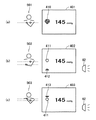
ステップS6での報知画面の一例を図5(a),(b),(c)に示す。
図5(a)を参照して、手首の高さと心臓の高さとがほぼ一致しており、両者のずれ幅が所定範囲内である状態501の場合、たとえば画面401に示されるような1つのマーク410が表示される。マーク410は、ハートマークに1拍分の脈波が重畳したような形状である。図5(b)を参照して、手首の位置が心臓の位置よりも所定範囲を越えて下方向にずれている状態502の場合、たとえば画面402に示されるようにハートマーク411の下に、上向きの三角マーク412が表示される。図5(c)を参照して、手首の位置が心臓の位置よりも所定範囲を越えて上方向にずれている状態503の場合、たとえば画面403に示されるようにハートマーク411の上に、下向きの三角マーク413が表示される。
An example of the notification screen in step S6 is shown in FIGS. 5 (a), (b), and (c).
Referring to FIG. 5A, in the case of a
なお、図5(b),(c)に示すような状態502,503の場合、ブザー62にて警告音を発生させてもよい。
In the case of
このように、三角マーク413の位置をずれた方向に一致させ、かつ、三角マーク413の向きにより矢印の機能も果たしている。さらに、ハートマーク411を基準として、三角マーク413の位置を、手首の高さに応じて変えている。したがって、被測定者は、カフ20を巻き付けた手首を、どちらの方向にどれ位、動かすべきか直感的に把握することができる。
In this manner, the position of the
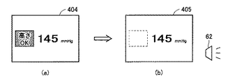
ステップS6での報知画面の他の例を図6(a),(b)に示す。
図6(a)を参照して、手首の高さと心臓の高さとがほぼ一致した状態(図5(a)の状態501)の場合、画面404に示されるように「高さOK」というメッセージが表示される。その後、両者のずれ幅が所定範囲を越えた場合、図6(b)の画面405に示されるように、「高さOK」というメッセージが非表示とされる。図6(b)の画面405とともにブザー62により警告音が発生されてもよい。
Another example of the notification screen in step S6 is shown in FIGS.
Referring to FIG. 6A, when the wrist height and the heart height substantially coincide with each other (
なお、特に図6に示したような報知形態の場合、報知処理部102は、ずれ幅の大きさに応じて、警告音のパターンを変えてもよい。
In particular, in the case of the notification form as shown in FIG. 6, the
再び図4を参照して、ずれ幅が所定範囲内になったと判断されると(ステップS4においてYES)、血圧測定が開始される(ステップS8)。 Referring to FIG. 4 again, when it is determined that the deviation width is within the predetermined range (YES in step S4), blood pressure measurement is started (step S8).
はじめに、加圧制御部104は、カフ20の加圧を開始する(ステップS10)。血圧計1は加圧測定方式であるため、血圧算出が可能となるように、単位時間当りの圧力増加量が一定となるように、徐々にカフ20を加圧する制御を行なう。加圧制御部104は、加圧期間中、発振回路33からの出力に基づいて、圧脈波を取得し、圧脈波の1拍ごとに脈波振幅を算出する(ステップS11)。算出された脈波振幅のデータは、カフ圧データと関連付けられて時系列にメモリ部42内に記録される。このようなメモリ部42内の脈波関連情報のデータ構造例については後述する。
First, the
加圧期間中、ずれ判断部112は、ずれ算出部101が算出したずれ幅が所定範囲内か否かを判断する(ステップS12)。加圧期間中、ずれ幅が所定範囲内であれば(ステップS12においてYES)、ステップS14に進む。一方、加圧制御中、ずれ幅が所定範囲外となると、「戻り処理」が実行される(ステップS30)。戻り処理については、図7および図8を参照して後に詳細に説明する。
During the pressurization period, the
ステップS14において、加圧制御部104は、所定値(たとえば200mmHg)まで加圧されたか否かを判断する。カフ圧が所定値に達していないと判断された場合(ステップS14においてNO)、ステップS11に戻り、上記処理(ステップS11,S12)を繰返す。
In step S14, the
カフ圧が所定値に達すると(ステップS14においてYES)、加圧は停止され(ステップS16)、カフ20内の空気が排気される(ステップS18)。同時に、血圧算出部108は、たとえばオシロメトリック法に従い、ステップS11で算出された脈波振幅とそのときのカフ圧とに基づいて、血圧値(最高血圧および最低血圧)を算出する(ステップS20)。なお、測定途中に戻り処理が実行された場合の具体的な血圧算出方法については後述する。
When the cuff pressure reaches a predetermined value (YES in step S14), the pressurization is stopped (step S16), and the air in the
最後に、出力処理部110は、測定結果すなわち算出された最高血圧および最低血圧を表示および記録する(ステップS22)。
Finally, the
なお、本実施の形態では、所定値に達するまで加圧制御を続けることとしたが、リアルタイムで血圧値を算出する場合には、最高血圧が算出された時点で加圧を終了してもよい。 In this embodiment, the pressurization control is continued until the predetermined value is reached. However, when the blood pressure value is calculated in real time, the pressurization may be terminated when the maximum blood pressure is calculated. .
(戻り処理)
ここで、本実施の形態における戻り処理について説明する。
(Return processing)
Here, the return process in the present embodiment will be described.
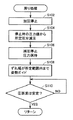
図7は、本発明の実施の形態の血圧測定処理における戻り処理を示すフローチャートである。 FIG. 7 is a flowchart showing a return process in the blood pressure measurement process according to the embodiment of the present invention.
図7を参照して、戻り処理部106は、まず、カフ20の加圧を停止する(ステップS102)。つまり、ポンプ51の駆動を停止する。
Referring to FIG. 7, the
次に、戻り処理部106は、閉じていた弁52を徐々に開いていき、測定停止時の圧力値から所定圧分減圧する(ステップS104)。
Next, the
戻り処理部106は、所定圧だけカフ圧を減圧させると、弁52を封鎖することにより減圧を停止し、圧力を保持する(ステップS106)。
When the
このようにして位置ずれが発生した時点よりも前の圧力値までカフ圧が戻されると、戻り処理部106は、ずれ算出部101が算出したずれ幅が所定範囲内になるまで姿勢のガイドを行なうとともに(ステップS108)、圧脈波が安定したか否かを判断する(ステップS110)。姿勢のガイドとしては、たとえば、上述のステップS6の報知処理と同様の処理を行なうこととしてよい。つまり、手首の高さと心臓の高さとの位置関係を示す情報を表示する処理が行なわれる。これにより、被測定者は、測定姿勢が正常になるように、すなわち手首の高さと心臓の高さとの高低差が所定値内に収まるように、カフ20を巻き付けた手首の位置を補正することができる。
When the cuff pressure is returned to the pressure value before the time point at which the positional deviation has occurred in this way, the
そして、圧脈波が安定すると(ステップS110においてYES)、メインルーチンに戻る。圧脈波が安定したか否かは、たとえば、圧脈波の振幅値がほぼ一定になったか否か、すなわち前後の振幅値の差が、所定数連続して所定値以下となったか否かで検出可能である。このように、圧脈波が安定したことを検出してから再加圧することで、血圧値の精度をより向上させることができる。 When the pressure pulse wave is stabilized (YES in step S110), the process returns to the main routine. Whether or not the pressure pulse wave has stabilized is, for example, whether or not the amplitude value of the pressure pulse wave has become substantially constant, that is, whether or not the difference between the amplitude values before and after has become a predetermined value or less continuously. Can be detected. Thus, the accuracy of the blood pressure value can be further improved by repressurizing after detecting that the pressure pulse wave is stable.
従来は、測定中に姿勢がくずれると、測定精度が保てないためエラー表示をして測定を終了していたが、本実施の形態によると、測定中に姿勢がくずれたとしても、被測定者に手首の位置の補正を導いて測定中止を回避することができる。したがって、被測定者は、始めから測定をやり直す必要がないため、トータルの測定時間を短縮することができる。 Conventionally, if the posture is lost during measurement, the measurement accuracy cannot be maintained and an error is displayed to terminate the measurement. However, according to this embodiment, even if the posture is broken during measurement, Measurement can be avoided by guiding the wrist position correction to the person. Therefore, the measurement subject does not need to repeat the measurement from the beginning, so that the total measurement time can be shortened.
以上説明したような戻り処理を図8を用いてより具体的に説明する。
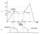
図8は、本発明の実施の形態における血圧測定処理にて実行される戻り処理について説明するための図である。図8(a)には、測定期間中に、発振回路33からの信号に基づいて得られる圧力値が、計時部45が計時する時間軸に沿って示される。図8(b)には、図8(a)における2つの特徴点P1,P2それぞれにおける圧脈波のイメージが示される。
The return processing as described above will be described more specifically with reference to FIG.
FIG. 8 is a diagram for describing the return process executed in the blood pressure measurement process according to the embodiment of the present invention. In FIG. 8A, the pressure value obtained based on the signal from the
図8(a)を参照して、加圧制御が開始され(開始時点を時間t0で表わしている)、時間t1において異常(位置ずれ)が検出されたとする(ステップS12)。時間t1において、測定された圧脈波は、図8(b)に示されるように、それまでの正常な波形とは異なり乱れた波形となっている。 Referring to FIG. 8A, it is assumed that pressurization control is started (the start time is represented by time t0), and an abnormality (position shift) is detected at time t1 (step S12). As shown in FIG. 8B, the measured pressure pulse wave at time t1 is a distorted waveform unlike the normal waveform so far.
位置ずれが発生すると、カフ20の加圧制御は停止される(ステップS102)。異常が検出されてから完全に加圧を停止するまでに多少のタイムラグがあるため、時間t2にて加圧が停止されたとする。その時点の圧力値を“PCa”と表わす。
When the displacement occurs, the pressurization control of the
圧力値PCaから減圧する所定の圧力値を“ΔTHp”で表わすと、圧力値は、停止時の圧力値PCaから所定圧ΔTHpを差し引いた圧力値“PCb”まで徐々に減圧される(ステップS104)。圧力値PCbまで減圧された時点が時間t3で表わされているとする。所定圧ΔTHpは、タイムラグを加味して、位置ずれが発生した特徴点P1の圧力値よりも一定量低くなるような値であるため、圧力値“PCb”は、特徴点P1の圧力値よりも一定量低い値ともいえる。 When a predetermined pressure value to be reduced from the pressure value PCa is represented by “ΔTHp”, the pressure value is gradually reduced to a pressure value “PCb” obtained by subtracting the predetermined pressure ΔTHp from the pressure value PCa at the time of stop (step S104). . It is assumed that the time point when the pressure is reduced to the pressure value PCb is represented by time t3. The predetermined pressure ΔTHp is a value that is lower by a certain amount than the pressure value of the feature point P1 where the positional deviation has occurred in consideration of the time lag, so the pressure value “PCb” is lower than the pressure value of the feature point P1. It can be said that it is a certain low value.
圧力値PCbまで一旦減圧されると、圧脈波が安定するまでその圧力値PCbが維持される(ステップS106)。時間t3〜t4の間で圧脈波の安定が検出されると、再び加圧が開始される(ステップS110でYES,ステップS10)。加圧が再開されてからの、位置ずれが発生した特徴点P1と同じ圧力レベルの特徴点P2(時間t5)においては、図8(b)に示されるように、測定された圧脈波は本来の正常な波形となる。 Once the pressure is reduced to the pressure value PCb, the pressure value PCb is maintained until the pressure pulse wave is stabilized (step S106). When the stability of the pressure pulse wave is detected between times t3 and t4, pressurization is started again (YES in step S110, step S10). At the feature point P2 (time t5) having the same pressure level as the feature point P1 where the positional deviation has occurred since the pressurization was resumed, as shown in FIG. 8B, the measured pressure pulse wave is The original normal waveform is obtained.
図8に示したような戻り処理が測定途中に挿入された場合、異常検出前の加圧制御において圧力値PCbであった時点を時間taと表わすと、血圧算出部108は、時間t0〜taまでに検出された圧脈波情報に基づく振幅値と、時間t4〜t6までに検出された圧脈波情報に基づく振幅値とに基づいて、最高血圧(図中“SYS”)および最低血圧(図中“DIA”)を算出することができる。
When the return process as shown in FIG. 8 is inserted in the middle of the measurement, if the time ta is the pressure value PCb in the pressurization control before the abnormality detection is represented as time ta, the blood
ここで、測定途中に戻り処理が実行された場合の、血圧算出部108による血圧算出方法について、図9を参照しながら説明する。
Here, the blood pressure calculation method by the blood
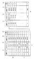
図9は、測定期間中にメモリ部42に記憶される圧脈波関連情報のデータ構造の一例を示す図である。
FIG. 9 is a diagram illustrating an example of a data structure of pressure pulse wave related information stored in the
図9を参照して、圧脈波関連情報には、4つの項目、すなわち、時間データを示す項目91と、カフ圧データを示す項目92と、算出された脈波振幅データを示す項目93と、中断フラグの項目94とが含まれる。カフ圧データは、制御値としてのカフ圧であり、脈波振幅データは、ステップS11で算出された脈波振幅の値を表わす。時間データとカフ圧データと脈波振幅データとが、対応付けられて記憶されている。なお、脈波振幅データは、カフ圧データと関連付けられていればよい。なお、脈波振幅データには、「0」も含む数値が記録されるものとする。
Referring to FIG. 9, the pressure pulse wave related information includes four items, that is,
中断フラグ(1または0)は、対応する脈波振幅を血圧算出に用いるか否かを識別するためのフラグである。中断フラグ、たとえば時間データ(またはカフ圧データ)に対応付けられて記憶されればよく、初期値として“0”が記憶される。 The interruption flag (1 or 0) is a flag for identifying whether or not the corresponding pulse wave amplitude is used for blood pressure calculation. The interrupt flag may be stored in association with, for example, time data (or cuff pressure data), and “0” is stored as an initial value.
図9(a)に、測定(加圧)開始から再加圧開始まで(t0〜t4)の圧脈波関連情報が示され、図9(b)に、再加圧開始から測定終了まで(t4〜t6)の圧脈波関連情報が示されているとする。なお、図9(b)において、再加圧が開始されたときの時間データを例として“101”としている。 FIG. 9A shows pressure pulse wave related information from the start of measurement (pressurization) to the start of repressurization (t0 to t4), and FIG. 9B shows from the start of repressurization to the end of measurement ( It is assumed that the pressure pulse wave related information of t4 to t6) is shown. In FIG. 9B, time data when repressurization is started is “101” as an example.
図9(a)を参照して、時間データ“10”の時点で加圧が停止されたと仮定する。この場合、時間データ“10”に対応するカフ圧データPC(10)が、図8(a)の圧力値PCaに相当する。 Referring to FIG. 9A, it is assumed that pressurization is stopped at time point “10”. In this case, the cuff pressure data PC (10) corresponding to the time data “10” corresponds to the pressure value PCa in FIG.
仮に、カフ圧データPC(10)から、所定圧ΔTHp差し引いた圧力値が、たとえばカフ圧データPC(6)の値であるとする。そうすると、PC(6)以降、再加圧がされるまでの間、つまり、時間データ“6”から“100”までの中断フラグを“1”にセットする。 Assume that the pressure value obtained by subtracting the predetermined pressure ΔTHp from the cuff pressure data PC (10) is, for example, the value of the cuff pressure data PC (6). Then, after PC (6), until the repressurization is performed, that is, the interruption flag from time data “6” to “100” is set to “1”.
このような場合、図9(a)のデータのうち、中断フラグが“1”である時間データ“6”以降のデータ群97は血圧算出に用いられない。血圧算出部108は、中断フラグが“0”である時間データを用いて血圧値を算出する。つまり、図9(a)の時間データ“1”〜“5”までのデータ群96と図9(b)の全データとをつなぎ合せることで、血圧値が算出される。より具体的には、図9(a)の振幅データAM(1)〜AM(5)、および、図9(b)の振幅データAM(101)以降の値に基づいて、最高血圧および最低血圧を算出する。
In such a case, among the data in FIG. 9A, the
このように、本実施の形態によると、測定の途中に姿勢がくずれたとしても、正しい姿勢の際の振幅データのみが血圧算出に用いられるため、測定精度を良好に保つことができる。 Thus, according to the present embodiment, even if the posture is broken during measurement, only the amplitude data in the correct posture is used for blood pressure calculation, so that the measurement accuracy can be kept good.
なお、本実施の形態では、加圧制御中に算出された脈波振幅を用いて血圧値を算出することとしたが、加圧制御中はカフ圧データ(圧脈波データ)のみを記録し、測定終了後につなぎ合わせたカフ圧データより脈波振幅を算出することで、血圧値を算出してもよい。 In this embodiment, the blood pressure value is calculated using the pulse wave amplitude calculated during the pressurization control. However, only the cuff pressure data (pressure pulse wave data) is recorded during the pressurization control. The blood pressure value may be calculated by calculating the pulse wave amplitude from the cuff pressure data connected after the measurement is completed.
なお、本実施の形態では、停止位置の圧力値から所定値(たとえば8mmHg)減圧したが、位置ずれ発生時の圧力値から所定値(たとえば5mmHg)減圧することとしてもよい。 In this embodiment, the pressure is reduced by a predetermined value (for example, 8 mmHg) from the pressure value at the stop position, but may be reduced by a predetermined value (for example, 5 mmHg) from the pressure value at the time of occurrence of the positional deviation.
または、本実施の形態では、停止位置の圧力値から所定値だけ減圧することとしたが、たとえば3拍分前の時点の圧力値を推定し、推定した圧力値まで減圧することとしてもよい。被測定者の1拍当りの時間から、3拍分前の時点の圧力値を推定することが可能である。この場合、位置ずれが発生した時点よりも所定拍分前の圧力値が、上記特定圧力値に対応する。 Alternatively, in the present embodiment, the pressure value is reduced by a predetermined value from the pressure value at the stop position. However, for example, the pressure value at a time point before three beats may be estimated, and the pressure value may be reduced to the estimated pressure value. It is possible to estimate a pressure value at a time point before three beats from the time per beat of the measurement subject. In this case, a pressure value a predetermined number of beats before the point in time when the positional deviation occurs corresponds to the specific pressure value.
または、減圧の際に圧脈波の振幅を算出し、位置ずれ発生直前の圧脈波の振幅値と算出した振幅値との差が所定値以内になった時点で減圧を停止してもよい。この場合、位置ずれが発生直前の振幅値との差が所定値以内である圧力値が、上記特定圧力値に対応する。 Alternatively, the pressure pulse wave amplitude may be calculated at the time of pressure reduction, and the pressure reduction may be stopped when the difference between the pressure pulse wave amplitude value immediately before the occurrence of the positional deviation and the calculated amplitude value falls within a predetermined value. . In this case, the pressure value whose difference from the amplitude value immediately before the occurrence of the positional deviation is within a predetermined value corresponds to the specific pressure value.
上記実施の形態では、加圧測定方式を例に説明したが、減圧測定方式にも適用することができる。つまり、異常が発生して減圧を停止すると、停止時の圧力値から所定圧分加圧して、手首の高さの補正がされてから減圧を再開することとしてよい。 In the above embodiment, the pressurization measurement method has been described as an example, but the present invention can also be applied to a decompression measurement method. That is, when the abnormality occurs and the pressure reduction is stopped, the pressure is increased by a predetermined pressure from the pressure value at the time of stop, and the pressure reduction may be resumed after the wrist height is corrected.
また、上記実施の形態では、位置ずれ発生時の圧力値にかかわらず、戻り処理をすることとしたが、高い圧力値で加圧を中断すると、被測定者が苦痛を感じる恐れも考えられる。したがって、所定値(たとえば130mmHg)より高い圧力値で位置ずれが発生した場合には、エラー表示とし、測定のやり直しを促してもよい。 In the above embodiment, the return process is performed regardless of the pressure value at the time of occurrence of the displacement, but if the pressurization is interrupted at a high pressure value, the subject may feel pain. Therefore, when a position shift occurs at a pressure value higher than a predetermined value (for example, 130 mmHg), an error display may be displayed to prompt the user to restart measurement.
または、測定精度をより向上させるために、血圧算出に用いられることが推定される圧力区間(たとえば60〜150mmHg)において位置ずれが発生した場合には、エラー表示とし、測定のやり直しを促してもよい。 Or, in order to further improve the measurement accuracy, if a position shift occurs in a pressure section (eg, 60 to 150 mmHg) that is estimated to be used for blood pressure calculation, an error display is displayed to prompt the measurement to be repeated. Good.
または、異常を検出して加圧(減圧)を停止してから、再加圧(減圧)するまでに特定時間を超えると、排気して測定中止としてもよい。また、当該特定時間は、異常検出時の圧力値に応じて変更できてもよい。具体的には、たとえば、異常検出時の圧力値と、時間とを対応付けたデータテーブルをメモリ部42に予め格納しておけば、実現可能である。 Alternatively, the measurement may be stopped by exhausting if a specific time is exceeded from the detection of abnormality to the stop of pressurization (decompression) until the repressurization (depressurization). The specific time may be changed according to the pressure value at the time of detecting the abnormality. Specifically, for example, it can be realized by storing in advance in the memory unit 42 a data table in which the pressure value at the time of abnormality detection is associated with time.
今回開示された実施の形態はすべての点で例示であって制限的なものではないと考えられるべきである。本発明の範囲は上記した説明ではなくて特許請求の範囲によって示され、特許請求の範囲と均等の意味および範囲内でのすべての変更が含まれることが意図される。 The embodiment disclosed this time should be considered as illustrative in all points and not restrictive. The scope of the present invention is defined by the terms of the claims, rather than the description above, and is intended to include any modifications within the scope and meaning equivalent to the terms of the claims.
1 電子血圧計、10 本体部、20 カフ、21 空気袋、30 エア系、31 エアチューブ、32 圧力センサ、33 発振回路、40 表示部、41 操作部、41A 電源スイッチ、41B 測定スイッチ、41C 停止スイッチ、41D メモリスイッチ、42 メモリ部、43 フラッシュメモリ、44 電源、45 計時部、46 データ入出力部、50 調整機構、51 ポンプ、52 弁、53 ポンプ駆動回路、54 弁駆動回路、60 角度センサ、61 A/Dコンバータ、62 ブザー、100 CPU、101 ずれ算出部、102 報知処理部、104 加圧制御部、106 戻り処理部、108 血圧算出部、110 出力処理部、112 ずれ判断部、132 記録媒体、601,602 重力加速度センサ。 1 Electronic Blood Pressure Monitor, 10 Main Body, 20 Cuff, 21 Air Bag, 30 Air System, 31 Air Tube, 32 Pressure Sensor, 33 Oscillator Circuit, 40 Display Unit, 41 Operation Unit, 41A Power Switch, 41B Measurement Switch, 41C Stop Switch, 41D Memory switch, 42 Memory unit, 43 Flash memory, 44 Power supply, 45 Timekeeping unit, 46 Data input / output unit, 50 Adjustment mechanism, 51 Pump, 52 Valve, 53 Pump drive circuit, 54 Valve drive circuit, 60 Angle sensor , 61 A / D converter, 62 buzzer, 100 CPU, 101 deviation calculation unit, 102 notification processing unit, 104 pressurization control unit, 106 return processing unit, 108 blood pressure calculation unit, 110 output processing unit, 112 deviation judgment unit, 132 Recording medium, 601 and 602 Gravity acceleration sensor.
Claims (9)
所定の基準方向に対する前記カフの角度を検出するための角度検出手段と、
前記カフ内の圧力を表わすカフ圧信号を検出するための圧力検出手段と、
前記カフ内の圧力を特定方向に変化させるための第1の圧力制御を行ない、かつ、前記第1の圧力制御の際に前記カフ圧信号を取得することにより圧脈波を測定するための圧力制御手段と、
前記第1の圧力制御が実行されている際に、前記角度検出手段からの出力に基づいて、前記カフの位置と仮想的な心臓位置との位置ずれが発生したか否かを判断するための判断手段と、
前記判断手段により位置ずれが発生したと判断された場合に、前記第1の圧力制御を停止し、前記特定方向とは逆方向に前記カフ内の圧力を変化させるための第2の圧力制御を行なうことにより、前記カフ内の圧力を、位置ずれが発生する前の圧力値を表わす特定圧力値まで戻すための戻り処理手段とを備え、
前記圧力制御手段は、前記戻り処理手段による処理の後に、前記第1の圧力制御を再開する、電子血圧計。 A cuff for wrapping around a predetermined measurement site of the subject,
Angle detection means for detecting the angle of the cuff with respect to a predetermined reference direction;
Pressure detecting means for detecting a cuff pressure signal representing the pressure in the cuff;
A pressure for measuring a pressure pulse wave by performing a first pressure control for changing the pressure in the cuff in a specific direction and acquiring the cuff pressure signal during the first pressure control. Control means;
When the first pressure control is executed, based on the output from the angle detection means, it is determined whether or not a positional deviation between the cuff position and the virtual heart position has occurred. Judgment means,
When it is determined by the determination means that a displacement has occurred, the first pressure control is stopped, and a second pressure control is performed to change the pressure in the cuff in a direction opposite to the specific direction. And a return processing means for returning the pressure in the cuff to a specific pressure value representing a pressure value before the positional deviation occurs,
The electronic blood pressure monitor, wherein the pressure control means resumes the first pressure control after the processing by the return processing means.
前記戻り処理手段は、前記角度検出手段からの出力に基づいて、前記カフの位置と前記心臓位置との位置関係を示す情報を前記表示手段に表示するための処理を行なう、請求項3に記載の電子血圧計。 A display means,
The return processing means performs processing for displaying information indicating a positional relationship between the position of the cuff and the heart position on the display means based on an output from the angle detection means. Electronic blood pressure monitor.
前記圧力制御手段は、前記カフの位置と前記心臓位置とが所定範囲内に収まったことを検知した場合に、前記第1の圧力制御を開始する、請求項5または6に記載の電子血圧計。 Before starting measurement, based on the output from the angle detection means, further comprising notification processing means for notifying the relationship between the position of the cuff and the heart position,
The electronic blood pressure monitor according to claim 5 or 6, wherein the pressure control means starts the first pressure control when detecting that the position of the cuff and the heart position are within a predetermined range. .
Priority Applications (7)
| Application Number | Priority Date | Filing Date | Title |
|---|---|---|---|
| JP2008321470A JP5309954B2 (en) | 2008-12-17 | 2008-12-17 | Electronic blood pressure monitor |
| CN2009801511425A CN102256540A (en) | 2008-12-17 | 2009-12-07 | Electronic apparatus for measuring blood pressure |
| PCT/JP2009/070473 WO2010071044A1 (en) | 2008-12-17 | 2009-12-07 | Electronic apparatus for measuring blood pressure |
| DE112009003748T DE112009003748T5 (en) | 2008-12-17 | 2009-12-07 | Electronic sphygmomanometer |
| RU2011129664/14A RU2011129664A (en) | 2008-12-17 | 2009-12-07 | ELECTRONIC Sphygmomanometer |
| TW098143043A TW201032775A (en) | 2008-12-17 | 2009-12-16 | Electronic blood pressure guage |
| US13/159,857 US20110245695A1 (en) | 2008-12-17 | 2011-06-14 | Electronic sphygmomanometer |
Applications Claiming Priority (1)
| Application Number | Priority Date | Filing Date | Title |
|---|---|---|---|
| JP2008321470A JP5309954B2 (en) | 2008-12-17 | 2008-12-17 | Electronic blood pressure monitor |
Publications (2)
| Publication Number | Publication Date |
|---|---|
| JP2010142370A true JP2010142370A (en) | 2010-07-01 |
| JP5309954B2 JP5309954B2 (en) | 2013-10-09 |
Family
ID=42268715
Family Applications (1)
| Application Number | Title | Priority Date | Filing Date |
|---|---|---|---|
| JP2008321470A Active JP5309954B2 (en) | 2008-12-17 | 2008-12-17 | Electronic blood pressure monitor |
Country Status (7)
| Country | Link |
|---|---|
| US (1) | US20110245695A1 (en) |
| JP (1) | JP5309954B2 (en) |
| CN (1) | CN102256540A (en) |
| DE (1) | DE112009003748T5 (en) |
| RU (1) | RU2011129664A (en) |
| TW (1) | TW201032775A (en) |
| WO (1) | WO2010071044A1 (en) |
Cited By (2)
| Publication number | Priority date | Publication date | Assignee | Title |
|---|---|---|---|---|
| CN103079463A (en) * | 2010-09-09 | 2013-05-01 | 西铁城控股株式会社 | Arm insertion type sphygmomanometer |
| JP2014171512A (en) * | 2013-03-06 | 2014-09-22 | Seiko Epson Corp | Biological information detecting apparatus and program |
Families Citing this family (17)
| Publication number | Priority date | Publication date | Assignee | Title |
|---|---|---|---|---|
| JP5309954B2 (en) * | 2008-12-17 | 2013-10-09 | オムロンヘルスケア株式会社 | Electronic blood pressure monitor |
| JP5248531B2 (en) * | 2010-01-08 | 2013-07-31 | パナソニック株式会社 | Wrist blood pressure monitor |
| JP5895673B2 (en) * | 2012-04-05 | 2016-03-30 | オムロンヘルスケア株式会社 | Sphygmomanometer |
| JP6191284B2 (en) * | 2013-07-02 | 2017-09-06 | Tdk株式会社 | Determination apparatus, method and program |
| US20170112388A1 (en) * | 2015-10-22 | 2017-04-27 | Welch Allyn, Inc. | Method and apparatus for performing biological measurements |
| US10368810B2 (en) | 2015-07-14 | 2019-08-06 | Welch Allyn, Inc. | Method and apparatus for monitoring a functional capacity of an individual |
| US11116397B2 (en) | 2015-07-14 | 2021-09-14 | Welch Allyn, Inc. | Method and apparatus for managing sensors |
| US10617350B2 (en) | 2015-09-14 | 2020-04-14 | Welch Allyn, Inc. | Method and apparatus for managing a biological condition |
| US10918340B2 (en) * | 2015-10-22 | 2021-02-16 | Welch Allyn, Inc. | Method and apparatus for detecting a biological condition |
| US10964421B2 (en) | 2015-10-22 | 2021-03-30 | Welch Allyn, Inc. | Method and apparatus for delivering a substance to an individual |
| TWI655928B (en) * | 2016-07-20 | 2019-04-11 | 宏達國際電子股份有限公司 | Physiological monitoring device, physiological monitoring method and computer readable recording medium for implementing the physiological monitoring method |
| JP6680155B2 (en) * | 2016-09-12 | 2020-04-15 | オムロンヘルスケア株式会社 | Blood pressure measuring device, control method of blood pressure measuring device, and program |
| JP6881288B2 (en) * | 2017-12-27 | 2021-06-02 | オムロンヘルスケア株式会社 | Biological information measuring devices, methods and programs |
| USD982755S1 (en) * | 2021-04-23 | 2023-04-04 | Shenzhen Jamr Technology Co., Ltd. | Electronic sphygmomanometer |
| USD979066S1 (en) * | 2021-04-26 | 2023-02-21 | Shenzhen Jamr Technology Co., Ltd. | Electronic sphygmomanometer |
| USD982756S1 (en) * | 2021-04-26 | 2023-04-04 | Shenzhen Jamr Technology Co., Ltd. | Electronic sphygmomanometer |
| USD979756S1 (en) * | 2021-04-26 | 2023-02-28 | Shenzhen Jamr Technology Co., Ltd. | Electronic sphygmomanometer |
Citations (4)
| Publication number | Priority date | Publication date | Assignee | Title |
|---|---|---|---|---|
| JPH0260633A (en) * | 1988-08-26 | 1990-03-01 | Koorin Denshi Kk | Cuff pressure controller for automatic hemadynamometer |
| JP2002034937A (en) * | 2000-07-26 | 2002-02-05 | Matsushita Electric Works Ltd | Sphygmomanometer |
| WO2002039893A1 (en) * | 2000-11-14 | 2002-05-23 | Omron Corporation | Electronic sphygmomanometer |
| WO2010071044A1 (en) * | 2008-12-17 | 2010-06-24 | オムロンヘルスケア株式会社 | Electronic apparatus for measuring blood pressure |
Family Cites Families (4)
| Publication number | Priority date | Publication date | Assignee | Title |
|---|---|---|---|---|
| JP3363261B2 (en) | 1994-06-27 | 2003-01-08 | 松下電工株式会社 | Sphygmomanometer |
| JP4462257B2 (en) | 2000-11-14 | 2010-05-12 | オムロンヘルスケア株式会社 | Electronic blood pressure monitor |
| CN100418471C (en) * | 2000-11-14 | 2008-09-17 | 欧姆龙健康医疗事业株式会社 | Electronic sphygmomanometer |
| JP3700635B2 (en) | 2001-09-28 | 2005-09-28 | オムロンヘルスケア株式会社 | Electronic blood pressure monitor |
-
2008
- 2008-12-17 JP JP2008321470A patent/JP5309954B2/en active Active
-
2009
- 2009-12-07 CN CN2009801511425A patent/CN102256540A/en active Pending
- 2009-12-07 WO PCT/JP2009/070473 patent/WO2010071044A1/en not_active Ceased
- 2009-12-07 DE DE112009003748T patent/DE112009003748T5/en not_active Withdrawn
- 2009-12-07 RU RU2011129664/14A patent/RU2011129664A/en not_active Application Discontinuation
- 2009-12-16 TW TW098143043A patent/TW201032775A/en unknown
-
2011
- 2011-06-14 US US13/159,857 patent/US20110245695A1/en not_active Abandoned
Patent Citations (4)
| Publication number | Priority date | Publication date | Assignee | Title |
|---|---|---|---|---|
| JPH0260633A (en) * | 1988-08-26 | 1990-03-01 | Koorin Denshi Kk | Cuff pressure controller for automatic hemadynamometer |
| JP2002034937A (en) * | 2000-07-26 | 2002-02-05 | Matsushita Electric Works Ltd | Sphygmomanometer |
| WO2002039893A1 (en) * | 2000-11-14 | 2002-05-23 | Omron Corporation | Electronic sphygmomanometer |
| WO2010071044A1 (en) * | 2008-12-17 | 2010-06-24 | オムロンヘルスケア株式会社 | Electronic apparatus for measuring blood pressure |
Cited By (3)
| Publication number | Priority date | Publication date | Assignee | Title |
|---|---|---|---|---|
| CN103079463A (en) * | 2010-09-09 | 2013-05-01 | 西铁城控股株式会社 | Arm insertion type sphygmomanometer |
| US9289139B2 (en) | 2010-09-09 | 2016-03-22 | Citizen Holdings Co., Ltd. | Blood pressure monitor |
| JP2014171512A (en) * | 2013-03-06 | 2014-09-22 | Seiko Epson Corp | Biological information detecting apparatus and program |
Also Published As
| Publication number | Publication date |
|---|---|
| DE112009003748T5 (en) | 2013-02-07 |
| US20110245695A1 (en) | 2011-10-06 |
| JP5309954B2 (en) | 2013-10-09 |
| TW201032775A (en) | 2010-09-16 |
| RU2011129664A (en) | 2013-01-27 |
| WO2010071044A1 (en) | 2010-06-24 |
| CN102256540A (en) | 2011-11-23 |
Similar Documents
| Publication | Publication Date | Title |
|---|---|---|
| JP5309954B2 (en) | Electronic blood pressure monitor | |
| US9326692B2 (en) | Blood pressure measurement device and blood pressure measurement method | |
| JP5200903B2 (en) | Electronic blood pressure monitor | |
| JP6149548B2 (en) | Electronic blood pressure monitor | |
| JP5200913B2 (en) | Electronic blood pressure monitor | |
| EP1195136A1 (en) | Biological information rating device | |
| US20110130667A1 (en) | Blood pressure information display device, blood pressure information display system, blood pressure information display method, and recording medium recorded with blood pressure information display program | |
| WO2010055783A1 (en) | Blood pressure measuring device with improved display | |
| JP5092779B2 (en) | Blood pressure measurement device | |
| JP2010194111A (en) | Blood pressure measuring device and blood pressure measuring program | |
| JP5200943B2 (en) | Blood pressure measurement device | |
| JP2010167136A (en) | Blood pressure information measuring instrument | |
| JP5035114B2 (en) | Electronic blood pressure monitor | |
| JP5343472B2 (en) | Electronic blood pressure monitor and blood pressure measurement control method | |
| JP5083037B2 (en) | Electronic blood pressure monitor | |
| JPH08215161A (en) | Electronic blood pressure monitor | |
| JP7347132B2 (en) | Blood pressure monitor, blood pressure calculation method, and program | |
| JP2019017553A (en) | Blood pressure measurement device | |
| JP2021074088A5 (en) | ||
| JP5353106B2 (en) | Electronic blood pressure monitor | |
| JP2007185233A (en) | Blood pressure measuring device | |
| JP2009219540A (en) | Hemodynamometer | |
| JP2011041684A (en) | Biological information measuring apparatus |
Legal Events
| Date | Code | Title | Description |
|---|---|---|---|
| A621 | Written request for application examination |
Free format text: JAPANESE INTERMEDIATE CODE: A621 Effective date: 20111128 |
|
| A131 | Notification of reasons for refusal |
Free format text: JAPANESE INTERMEDIATE CODE: A131 Effective date: 20130115 |
|
| A521 | Written amendment |
Free format text: JAPANESE INTERMEDIATE CODE: A523 Effective date: 20130307 |
|
| TRDD | Decision of grant or rejection written | ||
| A01 | Written decision to grant a patent or to grant a registration (utility model) |
Free format text: JAPANESE INTERMEDIATE CODE: A01 Effective date: 20130604 |
|
| A61 | First payment of annual fees (during grant procedure) |
Free format text: JAPANESE INTERMEDIATE CODE: A61 Effective date: 20130617 |
|
| R150 | Certificate of patent or registration of utility model |
Free format text: JAPANESE INTERMEDIATE CODE: R150 Ref document number: 5309954 Country of ref document: JP Free format text: JAPANESE INTERMEDIATE CODE: R150 |