JP6149548B2 - Electronic blood pressure monitor - Google Patents
Electronic blood pressure monitor Download PDFInfo
- Publication number
- JP6149548B2 JP6149548B2 JP2013138150A JP2013138150A JP6149548B2 JP 6149548 B2 JP6149548 B2 JP 6149548B2 JP 2013138150 A JP2013138150 A JP 2013138150A JP 2013138150 A JP2013138150 A JP 2013138150A JP 6149548 B2 JP6149548 B2 JP 6149548B2
- Authority
- JP
- Japan
- Prior art keywords
- envelope
- blood pressure
- pressure
- point
- amplitude
- Prior art date
- Legal status (The legal status is an assumption and is not a legal conclusion. Google has not performed a legal analysis and makes no representation as to the accuracy of the status listed.)
- Active
Links
Images


Classifications
-
- A—HUMAN NECESSITIES
- A61—MEDICAL OR VETERINARY SCIENCE; HYGIENE
- A61B—DIAGNOSIS; SURGERY; IDENTIFICATION
- A61B5/00—Measuring for diagnostic purposes; Identification of persons
- A61B5/02—Detecting, measuring or recording pulse, heart rate, blood pressure or blood flow; Combined pulse/heart-rate/blood pressure determination; Evaluating a cardiovascular condition not otherwise provided for, e.g. using combinations of techniques provided for in this group with electrocardiography or electroauscultation; Heart catheters for measuring blood pressure
- A61B5/021—Measuring pressure in heart or blood vessels
- A61B5/022—Measuring pressure in heart or blood vessels by applying pressure to close blood vessels, e.g. against the skin; Ophthalmodynamometers
- A61B5/02225—Measuring pressure in heart or blood vessels by applying pressure to close blood vessels, e.g. against the skin; Ophthalmodynamometers using the oscillometric method
-
- A—HUMAN NECESSITIES
- A61—MEDICAL OR VETERINARY SCIENCE; HYGIENE
- A61B—DIAGNOSIS; SURGERY; IDENTIFICATION
- A61B5/00—Measuring for diagnostic purposes; Identification of persons
- A61B5/74—Details of notification to user or communication with user or patient ; user input means
- A61B5/742—Details of notification to user or communication with user or patient ; user input means using visual displays
Description
この発明は電子血圧計に関し、より詳しくは、被測定部位の血圧をオシロメトリック法により測定する電子血圧計に関する。 The present invention relates to an electronic sphygmomanometer, and more particularly to an electronic sphygmomanometer that measures blood pressure at a measurement site by an oscillometric method.
従来、この種のオシロメトリック法による電子血圧計としては、例えば特許文献1(特開2006−247216号公報)に示すように、被測定部位(上腕など)に装着されたカフの圧力を変化させながら、カフ圧信号に重畳された被測定部位の脈波を表す脈波信号を取り出し、その脈波信号の振幅(脈波振幅)列に対する包絡線を用いて、所定のアルゴリズムにより血圧値(収縮期血圧(Systolic Blood Pressure)と拡張期血圧(Diastolic Blood Pressure)とを含む。以下同様。)を算出するものが知られている。具体的には、呼吸性の血圧変動や体動に伴う脈波振幅の誤差によって発生する血圧の測定誤差を解消するために、補間法などを用いて平滑化された包絡線を作成している。そして、その包絡線の最大ピークに対して高圧側、低圧側にそれぞれ閾値レベルを設定し、その包絡線がそれらの閾値レベルを横切る点の圧力を、それぞれ収縮期血圧、拡張期血圧として算出している。 Conventionally, as an electronic sphygmomanometer based on this type of oscillometric method, for example, as shown in Patent Document 1 (Japanese Patent Laid-Open No. 2006-247216), the pressure of a cuff attached to a measurement site (such as the upper arm) is changed. However, a pulse wave signal representing the pulse wave of the measurement site superimposed on the cuff pressure signal is taken out, and a blood pressure value (contraction) is determined by a predetermined algorithm using an envelope for the pulse wave signal amplitude (pulse wave amplitude) sequence. A device that calculates systolic blood pressure and diastolic blood pressure (the same applies hereinafter) is known. Specifically, in order to eliminate blood pressure measurement errors caused by respiratory blood pressure fluctuations and pulse wave amplitude errors associated with body movements, an envelope that has been smoothed using an interpolation method or the like is created. . Then, threshold levels are set on the high-pressure side and the low-pressure side with respect to the maximum peak of the envelope, and the pressure at the point where the envelope crosses those threshold levels is calculated as systolic blood pressure and diastolic blood pressure, respectively. ing.
ところで、血圧は常に一定ではなく、運動や呼吸などの身体的な影響や緊張や不安などの精神的な影響、または気温などの外部環境の影響などの様々な要因で時々刻々変化している。血圧を正しく測定するためには、安静状態で測定を行うことが推奨されているが、安静状態でも、呼吸に同期した血圧変動(これを「呼吸性変動」と呼ぶ。)は存在する。 By the way, blood pressure is not always constant, but changes every moment due to various factors such as physical influences such as exercise and breathing, mental influences such as tension and anxiety, and influences of the external environment such as temperature. In order to correctly measure the blood pressure, it is recommended to perform the measurement in a resting state, but even in the resting state, blood pressure fluctuations synchronized with breathing (referred to as “respiratory fluctuations”) exist.
ここで、上述の包絡線には、そのような呼吸性変動が含まれている。この結果、算出された血圧値が呼吸周期などに依存して異なる結果となり、算出された血圧値がばらつく可能性がある。 Here, the above-described envelope includes such a respiratory change. As a result, the calculated blood pressure value varies depending on the respiratory cycle and the calculated blood pressure value may vary.
例えば、図13、図14は、呼吸周期(つまり呼吸性変動の周期)がそれぞれ4秒間、8秒間である場合の、脈波信号の振幅列に対する包絡線(平滑化前の元の包絡線)EVOと、各測定点毎に±15mmHgの範囲内にあるN点(Nは自然数)のデータを用いた移動平均によって平滑化された包絡線EVNとを示している。それらの包絡線の最大ピークに対して高圧側、低圧側にそれぞれ閾値レベルThs,Thdが設定されている。図13から分かるように、呼吸周期が4秒間というように比較的速い場合は、包絡線に複数回分の呼吸性変動が含まれる。この結果、平滑化された包絡線EVNが閾値レベルThs,Thdを横切る点Xs,Xdの圧力は、呼吸性変動を加味した上限ラインEVU、下限ラインEVLが閾値レベルThs,Thdを横切る点の略中央に相当する。したがって、算出された圧力は略平均的な血圧値を表す。これに対して、図14から分かるように、呼吸周期が8秒間というように比較的遅い場合は、包絡線に1回分の呼吸性変動しか含まれない(この例では、カフ圧が約100mmHgのときに呼吸性変動が生じている。)。この結果、平滑化された包絡線EVNが閾値レベルThs,Thdを横切る点Xs′,Xd′の圧力は、呼吸性変動を加味した上限ラインEVU、下限ラインEV L が閾値レベルThs,Thdを横切る点の中央から外れている。このため、算出された圧力は平均的な血圧値であるとは言えない。
For example, FIG. 13 and FIG. 14 show an envelope for the amplitude sequence of the pulse wave signal (original envelope before smoothing) when the respiratory cycle (that is, the cycle of respiratory change) is 4 seconds and 8 seconds, respectively. EV O and envelope EV N smoothed by moving average using data of N points (N is a natural number) within a range of ± 15 mmHg for each measurement point are shown. Threshold levels Ths and Thd are set on the high-pressure side and the low-pressure side with respect to the maximum peak of those envelopes. As can be seen from FIG. 13, when the respiratory cycle is relatively fast, such as 4 seconds, the envelope includes multiple respiratory changes. As a result, smoothed envelope EV N threshold level Ths, Xs point across Thd, pressure Xd, the upper limit line EV U in consideration respiratory variation, the lower limit line EV L crosses a threshold level Ths, the Thd Corresponds to the approximate center of the point. Therefore, the calculated pressure represents a substantially average blood pressure value. On the other hand, as can be seen from FIG. 14, when the respiratory cycle is relatively slow, such as 8 seconds, the envelope includes only one respiratory change (in this example, the cuff pressure is about 100 mmHg). Sometimes respiratory fluctuations occur.) As a result, the pressures at the points Xs ′ and Xd ′ at which the smoothed envelope EV N crosses the threshold levels Ths and Thd are the upper limit line EV U and the lower limit line EV L taking into account the respiratory change, and the threshold levels Ths and Thd. Is off the center of the point that crosses For this reason, it cannot be said that the calculated pressure is an average blood pressure value.
このように、従来の電子血圧計では、算出された血圧値がばらつく可能性がある。このため、被験者は、なるべく平均的な血圧値を知ろうとして、複数回測定を繰り返しているのが実情である。この結果、被験者にとって血圧の測定は煩わしく、負担が大きいという問題がある。 Thus, in the conventional electronic blood pressure monitor, the calculated blood pressure value may vary. For this reason, the test subject is repeating the measurement several times in an attempt to know the average blood pressure value as much as possible. As a result, there is a problem that the measurement of blood pressure is troublesome and burdensome for the subject.
そこで、この発明の課題は、呼吸性変動を加味した平均的な血圧値を算出できる電子血圧計を提供することにある。 Therefore, an object of the present invention is to provide an electronic sphygmomanometer that can calculate an average blood pressure value that takes into account respiratory changes.
上記課題を解決するため、この発明の電子血圧計は、
被測定部位の血圧をオシロメトリック法により測定する電子血圧計であって、
被測定部位に装着されたカフの圧力を変化させ得るカフ圧制御部と、
上記カフの圧力を表すカフ圧信号を検出する圧力検出部と、
上記カフ圧信号に重畳された上記被測定部位の脈波を表す脈波信号を取り出して、その脈波信号が示す振幅の列を取得する脈波振幅列取得部と、
上記脈波振幅列取得部によって取得された上記振幅の列に対して、それらの振幅を結ぶ第1の包絡線を作成する第1の包絡線作成部と、
上記第1の包絡線における極大点、極小点をそれぞれ検出する極点検出部と、
上記脈波振幅列取得部によって取得された上記振幅の列のうち、上記極大点に対応する振幅の列に対して、それらの振幅を結ぶ極大点包絡線を作成する極大点包絡線作成部と、
上記脈波振幅列取得部によって取得された上記振幅の列のうち、上記極小点に対応する振幅の列に対して、それらの振幅を結ぶ極小点包絡線を作成する極小点包絡線作成部と、
収縮期血圧、拡張期血圧を求めるために、上記第1の包絡線における最大ピークの値に対してそれぞれ予め定められた割合の第1の閾値レベル、第2の閾値レベルを算出して設定する閾値レベル設定部と、
上記極大点包絡線、上記極小点包絡線の最大ピークよりも高圧側の部分が上記第1の閾値レベルを横切る点の2つの圧力値を求め、それら2つの圧力値の平均値を収縮期血圧として算出する収縮期血圧算出部と、
上記極大点包絡線、上記極小点包絡線の最大ピークよりも低圧側の部分が上記第2の閾値レベルを横切る点の2つの圧力値を求め、それら2つの圧力値の平均値を拡張期血圧として算出する拡張期血圧算出部と、
を備えたことを特徴とする。
In order to solve the above problems, an electronic sphygmomanometer according to the present invention provides:
An electronic sphygmomanometer that measures the blood pressure of a measurement site by an oscillometric method,
A cuff pressure control unit capable of changing the pressure of the cuff attached to the measurement site;
A pressure detector for detecting a cuff pressure signal representing the pressure of the cuff;
Taking out a pulse wave signal representing a pulse wave of the measurement site superimposed on the cuff pressure signal, and acquiring a pulse wave amplitude string acquisition unit for acquiring a string of amplitudes indicated by the pulse wave signal;
A first envelope creation unit that creates a first envelope connecting the amplitudes of the amplitude sequence acquired by the pulse wave amplitude sequence acquisition unit;
An extreme point detection unit for detecting a local maximum point and a local minimum point in the first envelope;
A maximum point envelope creation unit that creates a maximum point envelope connecting the amplitudes of the amplitude columns corresponding to the maximum points among the amplitude columns acquired by the pulse wave amplitude sequence acquisition unit; ,
A minimum point envelope creation unit that creates a minimum point envelope connecting the amplitudes of the amplitude sequence corresponding to the minimum point among the amplitude columns acquired by the pulse wave amplitude sequence acquisition unit; ,
In order to obtain the systolic blood pressure and the diastolic blood pressure, the first threshold level and the second threshold level of a predetermined ratio are respectively calculated and set with respect to the value of the maximum peak in the first envelope. A threshold level setting unit;
Two pressure values at a point where the portion on the high pressure side of the maximum peak envelope and the maximum peak of the minimum point envelope crosses the first threshold level are obtained, and the average value of the two pressure values is obtained as the systolic blood pressure. A systolic blood pressure calculator to calculate as
Two pressure values at the point where the lower pressure side of the maximum peak envelope and the maximum peak of the minimum point envelope crosses the second threshold level are obtained, and the average value of the two pressure values is obtained as the diastolic blood pressure. A diastolic blood pressure calculator that calculates as
It is provided with.
ここで、上記第1の包絡線、上記極大点包絡線および上記極小点包絡線は、典型的にはカフ圧を横軸、脈波振幅を縦軸としたグラフ上で表される。 Here, the first envelope, the maximum point envelope, and the minimum point envelope are typically represented on a graph with the cuff pressure as the horizontal axis and the pulse wave amplitude as the vertical axis.
この発明の電子血圧計では、測定中、カフ圧制御部が、被測定部位に装着されたカフの圧力を変化させる。上記カフの圧力の減圧過程または加圧過程で、圧力検出部が、上記カフの圧力を表すカフ圧信号を検出する。脈波振幅列取得部は、上記カフ圧信号に重畳された上記被測定部位の脈波を表す脈波信号を取り出して、その脈波信号が示す振幅の列を取得する。第1の包絡線作成部は、上記脈波振幅列取得部によって取得された上記振幅の列に対して、それらの振幅を結ぶ第1の包絡線を作成する。極点検出部は、上記第1の包絡線における極大点、極小点をそれぞれ検出する。極大点包絡線作成部は、上記脈波振幅列取得部によって取得された上記振幅の列のうち、上記極大点に対応する振幅の列に対して、それらの振幅を結ぶ極大点包絡線を作成する。極小点包絡線作成部は、上記脈波振幅列取得部によって取得された上記振幅の列のうち、上記極小点に対応する振幅の列に対して、それらの振幅を結ぶ極小点包絡線を作成する。閾値レベル設定部は、収縮期血圧、拡張期血圧を求めるために、上記第1の包絡線における最大ピークの値に対してそれぞれ予め定められた割合の第1の閾値レベル、第2の閾値レベルを算出して設定する。収縮期血圧算出部は、上記極大点包絡線、上記極小点包絡線の最大ピークよりも高圧側の部分が上記第1の閾値レベルを横切る点の2つの圧力値(これらを適宜「2つの高圧側圧力値」と呼ぶ。)を求め、それら2つの圧力値の平均値を収縮期血圧として算出する。また、拡張期血圧算出部は、上記極大点包絡線、上記極小点包絡線の最大ピークよりも低圧側の部分が上記第2の閾値レベルを横切る点の2つの圧力値(これらを適宜「2つの低圧側圧力値」と呼ぶ。)を求め、それら2つの圧力値の平均値を拡張期血圧として算出する。 In the electronic sphygmomanometer according to the present invention, the cuff pressure control unit changes the pressure of the cuff attached to the measurement site during measurement. In the pressure reducing process or pressurizing process of the cuff pressure, the pressure detection unit detects a cuff pressure signal representing the cuff pressure. The pulse wave amplitude sequence acquisition unit extracts a pulse wave signal representing the pulse wave of the measurement site superimposed on the cuff pressure signal, and acquires an amplitude sequence indicated by the pulse wave signal. The first envelope creation unit creates a first envelope that connects the amplitudes of the amplitude sequence acquired by the pulse wave amplitude sequence acquisition unit. The extreme point detection unit detects a local maximum point and a local minimum point in the first envelope. The maximal point envelope creation unit creates a maximal point envelope connecting the amplitudes of the amplitude sequence corresponding to the maximal point among the amplitude sequences acquired by the pulse wave amplitude sequence acquisition unit. To do. The minimum point envelope creation unit creates a minimum point envelope connecting the amplitudes of the amplitude columns corresponding to the minimum points among the amplitude columns acquired by the pulse wave amplitude sequence acquisition unit. To do. The threshold level setting unit obtains a systolic blood pressure and a diastolic blood pressure in a first threshold level and a second threshold level at a predetermined ratio with respect to the maximum peak value in the first envelope. Is calculated and set. The systolic blood pressure calculation unit calculates two pressure values at points where the portion on the high pressure side from the maximum peak of the maximum point envelope and the maximum peak of the minimum point envelope crosses the first threshold level (respectively, “two high pressures” The side pressure value is called “), and the average value of these two pressure values is calculated as the systolic blood pressure. In addition, the diastolic blood pressure calculation unit calculates two pressure values at the points where the lower pressure side of the maximum peak envelope and the maximum peak of the minimum point envelope crosses the second threshold level (respectively “2 Two low pressure side pressure values "), and the average of these two pressure values is calculated as the diastolic blood pressure.
ここで、上記極大点包絡線と上記極小点包絡線との間の差は、呼吸性変動を含んでいる。すなわち、上記2つの高圧側圧力値の間の差、上記2つの低圧側圧力値の間の差は、それぞれ呼吸性変動を含んでいる。したがって、上記収縮期血圧算出部が収縮期血圧として算出した上記2つの高圧側圧力値の平均値、上記拡張期血圧算出部が拡張期血圧として算出した上記2つの低圧側圧力値の平均値は、それぞれ呼吸性変動を加味した平均値であると言える。このように、この電子血圧計によれば、呼吸性変動を加味した平均的な血圧値を算出できる。 Here, the difference between the maximum point envelope and the minimum point envelope includes respiratory variation. That is, the difference between the two high pressure side pressure values and the difference between the two low pressure side pressure values each include a respiratory variation. Therefore, the average value of the two high-pressure pressure values calculated by the systolic blood pressure calculation unit as systolic blood pressure, and the average value of the two low-pressure pressure values calculated by the diastolic blood pressure calculation unit as diastolic blood pressure are: It can be said that each is an average value in consideration of respiratory changes. Thus, according to this electronic sphygmomanometer, it is possible to calculate an average blood pressure value in consideration of respiratory change.
さらに、算出された血圧値(収縮期血圧と拡張期血圧)を例えば表示器(液晶ディスプレイなど)に表示すれば、ユーザ(被験者を含む。以下同様。)は、被験者の呼吸性変動を加味した平均的な血圧値を知ることができる。したがって、被験者は、複数回測定を繰り返す必要が無い。この結果、被験者にとって血圧の測定が簡単になり、負担が軽減される。 Furthermore, if the calculated blood pressure values (systolic blood pressure and diastolic blood pressure) are displayed on, for example, a display (liquid crystal display or the like), the user (including the subject; the same applies hereinafter) takes into account the subject's respiratory change. You can know your average blood pressure. Therefore, the subject does not need to repeat the measurement multiple times. As a result, blood pressure can be easily measured for the subject, and the burden is reduced.
一実施形態の電子血圧計では、上記算出された収縮期血圧および拡張期血圧を表示する表示器を備えたことを特徴とする。 An electronic sphygmomanometer according to an embodiment includes a display for displaying the calculated systolic blood pressure and diastolic blood pressure.
この一実施形態の電子血圧計では、ユーザは上記表示器の表示内容を見ることによって、上記算出された収縮期血圧および拡張期血圧、すなわち被験者の呼吸性変動を加味した平均的な血圧値を、容易に認識できる。 In the electronic sphygmomanometer according to this embodiment, the user looks at the display content of the display, and thereby calculates the calculated systolic blood pressure and diastolic blood pressure, that is, the average blood pressure value taking into account the subject's respiratory fluctuation. Easy to recognize.
一実施形態の電子血圧計では、上記第1の包絡線が作成された振幅の列から特異点を除去して、上記第1の包絡線を補正する包絡線補正部を備えたことを特徴とする。 The electronic sphygmomanometer according to an embodiment includes an envelope correction unit that corrects the first envelope by removing a singular point from the amplitude column in which the first envelope is generated. To do.
本明細書で「特異点」は、次のように定義される。上記第1の包絡線が作成された振幅の列のうち、或る注目された振幅の値が、その振幅の前後に並ぶ振幅の値から予め定められた基準を超えて離れているとき、その注目された振幅を特異点とする。 As used herein, “singularity” is defined as follows. Among the amplitude columns in which the first envelope is generated, when a certain noted amplitude value is far beyond a predetermined reference from the amplitude values arranged before and after the amplitude, Let the noted amplitude be a singular point.
血圧の呼吸性変動は、呼吸に同期して周期的に発生し、上記第1の包絡線が作成された振幅の列のうち幾つかの連続した振幅の大または小の傾向として現れる。或る注目された振幅の値が、その振幅の前後に並ぶ振幅の値から予め定められた基準を超えて離れているとき、その注目された振幅は、血圧測定中の被験者の体動などに起因した非周期的な特異点であると考えられる。そこで、この一実施形態の電子血圧計では、包絡線補正部が、上記第1の包絡線が作成された振幅の列から特異点を除去して、上記第1の包絡線を補正する。これにより、上記極点検出部、上記極大点包絡線作成部、上記極小点包絡線作成部、上記閾値レベル設定部は、上記補正された第1の包絡線を用いて上述の処理を行う。そして、上記収縮期血圧算出部、拡張期血圧算出部は、それらの処理の結果を用いて、それぞれ収縮期血圧、拡張期血圧を算出する。したがって、算出された血圧値の精度が高まる。 Respiratory fluctuations in blood pressure occur periodically in synchronism with respiration, and appear as large or small trends in several consecutive amplitudes in the sequence of amplitudes from which the first envelope was created. When a certain noted amplitude value is separated from the amplitude values arranged before and after the amplitude by more than a predetermined reference, the noticed amplitude is related to the body movement of the subject during blood pressure measurement, etc. This is considered to be an aperiodic singular point. Therefore, in the electronic sphygmomanometer according to this embodiment, the envelope correction unit corrects the first envelope by removing the singular point from the amplitude column in which the first envelope is generated. Accordingly, the extreme point detection unit, the maximum point envelope generation unit, the minimum point envelope generation unit, and the threshold level setting unit perform the above-described processing using the corrected first envelope. The systolic blood pressure calculation unit and the diastolic blood pressure calculation unit calculate systolic blood pressure and diastolic blood pressure, respectively, using the results of these processes. Therefore, the accuracy of the calculated blood pressure value is increased.
一実施形態の電子血圧計では、
上記極大点包絡線、上記極小点包絡線をそれぞれ平滑化する平滑化部を備えたことを特徴とする。
In one embodiment of the electronic blood pressure monitor,
A smoothing unit is provided for smoothing the maximum point envelope and the minimum point envelope.
この一実施形態の電子血圧計では、平滑化部が、上記極大点包絡線、上記極小点包絡線をそれぞれ平滑化する。これにより、上記収縮期血圧算出部は、上記平滑化された極大点包絡線と上記平滑化された極小点包絡線とを用いて上記収縮期血圧を算出する。また、上記拡張期血圧算出部は、上記平滑化された極大点包絡線と上記平滑化された極小点包絡線とを用いて上記拡張期血圧を算出する。このようにした場合、上記2つの高圧側圧力値、上記2つの低圧側圧力値のノイズが低減されて、算出された血圧値(上記収縮期血圧と上記拡張期血圧)の精度が高まる。 In the electronic sphygmomanometer according to the embodiment, the smoothing unit smoothes the maximum point envelope and the minimum point envelope. Accordingly, the systolic blood pressure calculation unit calculates the systolic blood pressure using the smoothed maximum point envelope and the smoothed minimum point envelope. The diastolic blood pressure calculation unit calculates the diastolic blood pressure using the smoothed maximum point envelope and the smoothed minimum point envelope. In this case, noises of the two high pressure side pressure values and the two low pressure side pressure values are reduced, and the accuracy of the calculated blood pressure values (the systolic blood pressure and the diastolic blood pressure) is increased.
以上より明らかなように、この発明の電子血圧計によれば、呼吸性変動を加味した平均的な血圧値を算出できる。 As is clear from the above, according to the electronic sphygmomanometer of the present invention, an average blood pressure value can be calculated in consideration of respiratory changes.
以下、この発明の実施の形態を、図面を参照しながら詳細に説明する。 Hereinafter, embodiments of the present invention will be described in detail with reference to the drawings.
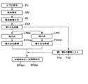
図1は、この発明の一実施形態の電子血圧計(全体を符号1で示す。)の概略的なブロック構成を示している。この血圧計1は、カフ20と、本体10と、この本体10に搭載された、制御部としてのCPU(Central Processing Unit)100、表示器50、記憶部としてのメモリ51、操作部52、電源部53、ポンプ32、弁33、および圧力センサ31を含む。また、本体10は、この本体10に搭載された、圧力センサ31からの出力を周波数に変換する発振回路310、ポンプ32を駆動するポンプ駆動回路320、弁33を駆動する弁駆動回路330を有する。
FIG. 1 shows a schematic block configuration of an electronic sphygmomanometer (the whole is denoted by reference numeral 1) according to an embodiment of the present invention. The
上記表示器50は、ディスプレイおよびインジケータ等を含み、CPU100からの制御信号に従って所定の情報を表示する。
The
上記操作部52は、電源部53をON(オン)またはOFF(オフ)するための指示の入力を受け付ける電源スイッチ52Aと、血圧の測定開始の指示を受け付けるための測定スイッチ52Bと、測定停止の指示を受け付けるための停止スイッチ52Cと、登録された複数のユーザの中から被験者となるユーザを選択するための使用者選択スイッチ52Dとを有する。これらのスイッチ52A,52B,52C,52Dは、ユーザによる指示に応じた操作信号をCPU100に入力する。
The operation unit 52 includes a
上記メモリ51は、血圧計1を制御するためのプログラムのデータ、血圧計1を制御するために用いられるデータ、血圧計1の各種機能を設定するための設定データ、および血圧値の測定結果のデータなどを記憶する。また、メモリ51は、プログラムが実行されるときのワークメモリなどとして用いられる。
The
上記CPU100は、メモリ51に記憶された血圧計1を制御するためのプログラムに従ってカフ圧制御部として働いて、操作部51からの操作信号に応じて、ポンプ32や弁33を駆動する制御を行う。また、CPU100は、圧力センサ31からの信号に基づいて、血圧値を算出し、表示器50およびメモリ51を制御する。
The
上記電源部53は、CPU100、圧力センサ31、ポンプ32、弁33、表示器50、メモリ51、発振回路310、ポンプ駆動回路320、および弁駆動回路330の各部に電力を供給する。
The
上記ポンプ32は、カフ20に内包された流体袋22内の圧力(カフ圧)を加圧するために、流体袋22に空気を供給する。弁33は、流体袋22の空気を排出し、または封入してカフ圧を制御するために開閉される。ポンプ駆動回路320は、ポンプ32をCPU100から与えられる制御信号に基づいて駆動する。弁駆動回路330は、弁33をCPU100から与えられる制御信号に基づいて開閉する。
The
上記圧力センサ31と発振回路310は、カフの圧力を検出する圧力検出部として働く。圧力センサ31は、例えば、ピエゾ抵抗式圧力センサであり、カフ用エアチューブ39を介して、ポンプ32、弁33およびカフ20に内包されている流体袋22に接続されている。この例では、発振回路310は、圧力センサ31からのピエゾ抵抗効果による電気抵抗の変化に基づく電気信号値に基づき発振して、圧力センサ31の電気信号値に応じた周波数を有する周波数信号をCPU100に出力する。
The
一般的なオシロメトリック法に従って血圧を測定する場合、概ね、次のような動作が行なわれる。すなわち、被験者の被測定部位(腕など)に予めカフを巻き付けておき、測定時には、ポンプ・弁を制御して、カフ圧を最高血圧より高く加圧し、その後徐々に減圧していく。この減圧する過程において、カフ圧を圧力センサで検出し、被測定部位の動脈で発生する動脈容積の変動を脈波信号として取り出す。その時のカフ圧の変化に伴う脈波信号の振幅の変化(主に立ち上がりと立ち下がり)に基づいて、最高血圧(収縮期血圧:Systolic Blood Pressure)と最低血圧(拡張期血圧:Diastolic Blood Pressure)とを算出する。 When measuring blood pressure according to a general oscillometric method, the following operation is generally performed. That is, a cuff is wound around the measurement site (arm or the like) of the subject in advance, and at the time of measurement, the pump / valve is controlled so that the cuff pressure is higher than the maximum blood pressure and then gradually reduced. In the process of reducing the pressure, the cuff pressure is detected by a pressure sensor, and the fluctuation of the arterial volume generated in the artery at the measurement site is extracted as a pulse wave signal. The systolic blood pressure and systolic blood pressure (diastolic blood pressure) based on changes in the amplitude of the pulse wave signal (mainly rising and falling) accompanying the change in cuff pressure at that time And calculate.
この血圧計1では、CPU100によって、図2のフローに従ってオシロメトリック法により被験者の血圧値が測定される。
In the
具体的には、電源スイッチ52AがONされた状態で測定スイッチ52Bが押されると、図2に示すように、血圧計1は血圧測定を開始する。血圧測定開始に際して、CPU100は、処理用メモリ領域を初期化し、弁駆動回路330に制御信号を出力する。弁駆動回路330は、制御信号に基づいて、弁33を開放してカフ20の流体袋22内の空気を排気する。続いて、圧力センサ31の0mmHgの調整を行う制御を行う。
Specifically, when the
血圧測定を開始すると、まず、CPU100は、弁駆動回路330を介して弁33を閉鎖し、その後、ポンプ駆動回路320を介してポンプ32を駆動して、流体袋22に空気を送る制御を行う。これにより、流体袋22を膨張させるとともにカフ圧を徐々に加圧していく(ステップST101)。
When the blood pressure measurement is started, the
カフ圧が加圧されて所定の圧力に達すると(ステップST102でYES)、CPU100は、ポンプ駆動回路320を介してポンプ32を停止し、その後、弁駆動回路330を介して弁33を徐々に開放する制御を行う。これにより、流体袋22を収縮させるとともにカフ圧を徐々に減圧していく(ステップST103)。
When the cuff pressure is increased and reaches a predetermined pressure (YES in step ST102), the
ここで、所定の圧力とは、被験者の収縮期血圧よりも十分高い圧力(例えば、収縮期血圧+30mmHg)であり、予めメモリ51に記憶されているか、カフ圧の加圧中にCPU100が収縮期血圧を所定の算出式により推定して決定する(例えば特開2001−70263号公報参照。)。
Here, the predetermined pressure is a pressure sufficiently higher than the systolic blood pressure of the subject (for example, the systolic blood pressure + 30 mmHg), and is stored in the
また、減圧速度については、カフの加圧中に目標となる目標減圧速度を設定し、その目標減圧速度になるようにCPU100が弁33の開口度を制御する(同公報参照。)。
As for the pressure reduction speed, a target target pressure reduction speed is set during the pressurization of the cuff, and the
上記減圧過程において、カフ20を介して、カフ20の圧力を表すカフ圧信号(符号Pcで表す。)を圧力センサ31が検出する。CPU100は、このカフ圧信号Pcに基づいて、オシロメトリック法により後述のアルゴリズムを適用して血圧値(収縮期血圧と拡張期血圧)を算出する(ステップST104)。なお、血圧値の算出は、減圧過程に限らず、加圧過程において行われてもよい。
In the decompression process, the
血圧値を算出して決定すると(ステップST105でYES)、CPU100は、算出した血圧値を表示器50へ表示し(ステップST106)、血圧値をメモリ51へ保存する制御を行う(ステップST107)。
When the blood pressure value is calculated and determined (YES in step ST105), the
次に、停止スイッチ52Cが押されると、CPU100は、弁駆動回路330を介して弁33を開放し、カフ20の流体袋22内の空気を排気する制御を行う(ステップST108)。
Next, when the
この後、上記電源スイッチ52Aが押されると、血圧測定を終了する。
Thereafter, when the
(第1の例)
図3は、血圧値を算出するために、電子血圧計1のCPU100(ソフトウェア)によって構成される要素を例示している。この第1の例では、血圧値を算出するための要素は、脈波振幅列取得部61、第1の包絡線作成部62、極点検出部63、極大点包絡線作成部64、極小点包絡線作成部65、閾値レベル設定部66、収縮期血圧算出部67および拡張期血圧算出部68を含んでいる。図4は、図3中のそれらの要素によって血圧値を算出する際の処理の流れを示している。なお、この第1の例では、図3中に破線の枠で示した包絡線補正部71および平滑化処理部72は除外される。
(First example)
FIG. 3 exemplifies elements configured by the CPU 100 (software) of the
図3と図4を主に参照しながら、カフ圧信号Pcに基づいて血圧値を算出する仕方を説明する。 A method of calculating the blood pressure value based on the cuff pressure signal Pc will be described with reference mainly to FIGS. 3 and 4.
i) まず、図3中の脈波振幅列取得部61は、図4中に示すように、上述の圧力センサ31によって検出されたカフ圧信号Pcを受けて、カフ圧信号Pcに重畳された被測定部位の脈波を表す脈波信号SMを取り出す。
i) First, the pulse wave amplitude
ここで、カフ圧信号Pcは、図5(A)に示すように、時間経過に伴って略直線的に上昇(加圧過程)または低下(減圧過程)する圧力に対して、1拍毎の動脈容積変化に伴う変動成分が重畳された信号である。脈波振幅列取得部61は、ハイパスフィルタ(HPF)を通してカフ圧信号Pcから図5(B)に示すような変動成分(HPF出力)を取り出し、図6に示すような脈波信号SMとして出力する。この例では、図6(減圧過程に相当)に示すように、脈波信号SMは、動脈容積の変動に応じて、測定開始から約12秒で大きくなり始め、約16秒で最大となり、約20秒でほぼ消失している。
Here, as shown in FIG. 5 (A), the cuff pressure signal Pc corresponds to a pressure that rises (pressurization process) or decreases (decompression process) substantially linearly with time. It is a signal on which a fluctuation component accompanying an arterial volume change is superimposed. The pulse wave amplitude
そして、脈波振幅列取得部61は、その脈波信号SMが示す振幅(以下、適宜「脈波振幅」と呼ぶ。)の列ALを取得する。脈波振幅の列ALは、この例では図7中に示すように、カフ圧を横軸にとって、1拍毎の振幅(ピーク値)AM1,AM2,…,AMi,…の列ALとして表される。
Then, the pulse wave amplitude
ii) 次に、図3中の第1の包絡線作成部62は、図4中に示すように、脈波振幅列取得部61によって取得された脈波振幅の列ALに対して、それらの振幅を結ぶ第1の包絡線EV1を作成する。ここで、第1の包絡線EV1は、図7中に示すように、呼吸性変動による凹凸を有している。
ii) Next, as shown in FIG. 4, the first
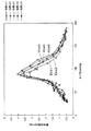
図8は、参考のために、被験者の呼吸周期が既知である場合に、上記脈波信号SMの脈波振幅の列ALから呼吸周期の位相α1,α2,…,α5毎に振幅の列を取得し、それらの位相α1,α2,…,α5毎の振幅の列についてそれぞれ包絡線EVα1,EVα2,…,EVα5を作成した例を示している。位相α1,α2,…,α5は、1呼吸周期を360°として、60°ずつ異なっている。この図8の例では、EVα5は呼吸性変動が極大を示すときの包絡線に相当し、また、EVα2は呼吸性変動が極小を示すときの包絡線に相当する。平均的な血圧値を求めるためには、このような呼吸性変動が極大を示すときの包絡線、呼吸性変動が極小を示すときの包絡線を、それぞれ呼吸性変動を加味した上限ライン、下限ラインと考えることができる。 FIG. 8 shows, for reference, when the subject's respiratory cycle is known, an amplitude column is generated for each phase α1, α2,..., Α5 of the respiratory cycle from the pulse wave amplitude column AL of the pulse wave signal SM. In this example, envelopes EVα1, EVα2,..., EVα5 are respectively obtained for the amplitude columns for the phases α1, α2,. The phases α1, α2,..., Α5 are different from each other by 60 °, where one breathing cycle is 360 °. In the example of FIG. 8, EVα5 corresponds to an envelope when the respiratory variation shows a maximum, and EVα2 corresponds to an envelope when the respiratory change shows a minimum. In order to obtain the average blood pressure value, the upper limit line and lower limit for the respiratory fluctuation are taken into account when the respiratory fluctuation shows the maximum and the envelope when the respiratory fluctuation shows the minimum, respectively. Can be considered a line.
iii) そこで、図3中の極点検出部63は、図4中に示すように、第1の包絡線EV1における極大点Lmax、極小点Lminをそれぞれ検出する。極大点Lmax、極小点Lminは、それぞれ複数の点の列をなす。
iii) Therefore, the extreme
iv) 次に、図3中の極大点包絡線作成部64は、脈波振幅列取得部61によって取得された脈波振幅の列ALのうち、極大点Lmaxに対応する振幅の列に対して、図9中に示すように、それらの振幅を結ぶ極大点包絡線EVmaxを作成する。一方、図3中の極小点包絡線作成部65は、脈波振幅列取得部61によって取得された脈波振幅の列ALのうち、極小点Lminに対応する振幅の列に対して、図9中に示すように、それらの振幅を結ぶ極小点包絡線EVminを作成する。
iv) Next, the maximal point
v) また、図3中の閾値レベル設定部66は、収縮期血圧BPsys、拡張期血圧BPdiaを求めるために、第1の包絡線EV1における最大ピークEV1Pの値に対してそれぞれ予め定められた割合の第1の閾値レベルThs、第2の閾値レベルThdを算出して設定する。この例では、第1の閾値レベルThsを最大ピークEV1Pの値の40%とし、また、第2の閾値レベルThdを最大ピークEV1Pの値の50%とする。
v) Further, the threshold
vi) 次に、図3中の収縮期血圧算出部67は、図4および図9中に示すように、極大点包絡線EVmax、極小点包絡線EVminの最大ピークEVmaxP,EVminPよりも高圧側の部分が第1の閾値レベルThsを横切る点の2つの圧力値Pc1,Pc2を求め、それら2つの圧力値の平均値(Pc1+Pc2)/2を収縮期血圧BPsysとして算出する。また、図3中の拡張期血圧算出部68は、図4および図9中に示すように、極大点包絡線EVmax、極小点包絡線EVminの最大ピークEVmaxP,EVminPよりも低圧側の部分が第2の閾値レベルThdを横切る点の2つの圧力値Pc3,Pc4を求め、それら2つの圧力値の平均値(Pc3+Pc4)/2を拡張期血圧BPdiaとして算出する。
vi) Next, as shown in FIGS. 4 and 9, the systolic blood
ここで、極大点包絡線EVmax、極小点包絡線EVminは、それぞれ呼吸性変動の上限ライン、下限ラインに相当する。したがって、上記2つの高圧側圧力値の平均値(Pc1+Pc2)/2、上記2つの低圧側圧力値の平均値(Pc3+Pc4)/2は、それぞれ呼吸性変動を加味した平均値であると言える。このように、この電子血圧計1によれば、呼吸性変動を加味した平均的な血圧値を算出できる。
Here, the maximum point envelope EVmax and the minimum point envelope EVmin correspond to an upper limit line and a lower limit line of respiratory change, respectively. Therefore, it can be said that the average value (Pc1 + Pc2) / 2 of the two high-pressure side pressure values and the average value (Pc3 + Pc4) / 2 of the two low-pressure side pressure values are average values taking into account respiratory changes. Thus, according to this
さらに、算出された血圧値(収縮期血圧BPsysと拡張期血圧BPdia)は、表示器50に表示される。したがって、ユーザは、被験者の呼吸性変動を加味した平均的な血圧値を知ることができる。したがって、被験者は、複数回測定を繰り返す必要が無い。この結果、被験者にとって血圧の測定が簡単になり、負担が軽減される。
Further, the calculated blood pressure values (systolic blood pressure BPsys and diastolic blood pressure BPdia) are displayed on the
上の例では、第1の閾値レベルThsを最大ピークEV1Pの値の40%とし、また、第2の閾値レベルThdを最大ピークEV1Pの値の50%としたが、これに限られるものではない。例えば、最大ピークEV1Pの値に対する閾値レベルの割合を変えて、第1の閾値レベルThsを最大ピークEV1Pの値の50%とし、また、第2の閾値レベルThdを最大ピークEV1Pの値の70%としてもよい。また、第1の包絡線EV1における最大ピークEV1Pの値を基準として閾値レベルの割合を設定するのに代えて、極大点包絡線EVmaxにおける最大ピークEVmaxPの値または極小点包絡線EVminにおける最大ピークEVminPの値を基準として閾値レベルの割合を設定してもよい。 In the above example, the first threshold level Ths is set to 40% of the value of the maximum peak EV1P, and the second threshold level Thd is set to 50% of the value of the maximum peak EV1P. However, the present invention is not limited to this. . For example, the ratio of the threshold level to the value of the maximum peak EV1P is changed so that the first threshold level Ths is 50% of the value of the maximum peak EV1P, and the second threshold level Thd is 70% of the value of the maximum peak EV1P. It is good. Further, instead of setting the threshold level ratio based on the value of the maximum peak EV1P in the first envelope EV1, the value of the maximum peak EVmaxP in the maximum point envelope EVmax or the maximum peak EVminP in the minimum point envelope EVmin. The threshold level ratio may be set based on the value of.
また、算出された収縮期血圧BPsysに対して上記2つの高圧側圧力値Pc1,Pc2の間の差(Pc1−Pc2)が予め定められた割合(例えば数%〜10%の範囲で設定される)を超えていれば、または、算出された拡張期血圧BPdiaに対して上記2つの低圧側圧力値Pc3,Pc4の間の差(Pc3−Pc4)が予め定められた割合(例えば数%〜10%の範囲で設定される)を超えていれば、CPU100は、表示器50に、算出された血圧値(収縮期血圧BPsysと拡張期血圧BPdia)とともに、「血圧変動が大きいので再測定をお勧めします」というメッセージを表示して報知してもよい。
Further, the difference (Pc1−Pc2) between the two high pressure side pressure values Pc1 and Pc2 with respect to the calculated systolic blood pressure BPsys is set in a predetermined ratio (for example, a range of several% to 10%). ) Or a difference (Pc3−Pc4) between the two low pressure side pressure values Pc3 and Pc4 with respect to the calculated diastolic blood pressure BPdia is a predetermined ratio (for example, several% to 10%) If it exceeds the threshold value (set in the range of%), the
また、このようなメッセージを表示するのとともに、またはメッセージの表示に代えて、例えばアラーム音によって、そのことを報知してもよい。 In addition to displaying such a message or instead of displaying the message, this may be notified by an alarm sound, for example.
このような報知により、ユーザは、正しい測定ができなかった可能性があり、そのため、時間をおいて再測定する必要があることを容易に認識できる。 By such notification, the user may be able to easily recognize that there is a possibility that correct measurement has not been performed, and therefore it is necessary to perform re-measurement after a certain time.
(第2の例)
この第2の例では、図3中の全部の要素によって血圧値を算出する。すなわち、第1の例で既に説明した脈波振幅列取得部61、第1の包絡線作成部62、極点検出部63、極大点包絡線作成部64、極小点包絡線作成部65、閾値レベル設定部66、収縮期血圧算出部67および拡張期血圧算出部68に加えて、図3中に破線の枠で示した包絡線補正部71および平滑化処理部72が機能する。
(Second example)
In this second example, the blood pressure value is calculated using all the elements in FIG. That is, the pulse wave amplitude
図10は、図3中の全部の要素によって血圧値を算出する際の処理の流れを示している。この図10の処理は、図4の処理と概ね同様の流れを有している。この図10の処理では、包絡線補正部71によって第1の包絡線EV1が作成された振幅の列ALから特異点を除去する補正(特異点除去補正)RAを行う処理と、平滑化処理部72によって極大点包絡線EVmax、極小点包絡線EVminに対してそれぞれ平滑化ALS1,ALS2を行う処理が追加されている点が異なっている。以下では、簡単のため、第1の例と重複する説明は省略し、第1の例に対して異なる点のみについて説明する。
FIG. 10 shows the flow of processing when blood pressure values are calculated using all the elements in FIG. The process of FIG. 10 has a flow generally similar to the process of FIG. In the processing of FIG. 10, processing for performing correction (singular point removal correction) RA for removing singular points from the amplitude column AL in which the first envelope EV1 is generated by the
i) 図11は、第1の包絡線EV1が作成された振幅の列ALから特異点を除去する補正(特異点除去補正)RAの仕方を例示している。この特異点除去補正RAは、第1の包絡線EV1から、血圧測定中の被験者の体動などに起因した、呼吸性変動とは異なる非周期的な成分を除去しようとするものである。 i) FIG. 11 illustrates a method of correction RA (singular point removal correction) RA for removing singular points from the amplitude column AL in which the first envelope EV1 is generated. This singular point removal correction RA is intended to remove a non-periodic component different from the respiratory fluctuation caused by the body movement of the subject during blood pressure measurement from the first envelope EV1.
この例では、第1の包絡線EV1が作成された振幅の列ALのうち、或る注目された振幅(これAMiとする。)の値が、その振幅の前後に並ぶ振幅(これらをAMi−1、AMi+1とする。)の値から予め定められた基準を超えて離れているとき、その注目された振幅AMiを特異点として定義する。具体的には、次の3つの式によって、各振幅に対応する点毎に特異点であるか否かを判定する。まず、振幅AMiが
AMi<(AMi−1+AMi+1)/4 …(1)
を満たすならば、振幅AMiを特異点とする。この式(1)の右辺は、前後に並ぶ振幅AMi−1、AMi+1の平均値の0.5倍という意味をもつ。
In this example, in the amplitude column AL in which the first envelope EV1 is generated, the amplitude of a certain noticed amplitude (hereinafter referred to as AM i ) is an amplitude (these are referred to as AM) arranged before and after the amplitude. i-1 and AM i + 1 )), when the value exceeds a predetermined reference, the noticed amplitude AM i is defined as a singular point. Specifically, it is determined whether or not each point corresponding to each amplitude is a singular point by the following three equations. First, the amplitude AM i is AM i <(AM i−1 + AM i + 1 ) / 4 (1)
If it satisfies, the amplitude AM i is set as a singular point. The right side of the equation (1) has a meaning of 0.5 times the average value of the amplitudes AM i−1 and AM i + 1 arranged in front and rear.
また、振幅AMiが
(AMi−1+AMi+1)/4<AMi≦3(AMi−1+AMi+1)/4
…(2)
を満たすならば、振幅AMiを特異点とはしない。この式(2)の右辺は、前後に並ぶ振幅AMi−1、AMi+1の平均値の1.5倍という意味をもつ。
Further, the amplitude AM i is (AM i−1 + AM i + 1 ) / 4 <AM i ≦ 3 (AM i−1 + AM i + 1 ) / 4.
... (2)
If it satisfies, the amplitude AM i is not a singular point. The right side of the equation (2) has a meaning of 1.5 times the average value of the amplitudes AM i−1 and AM i + 1 arranged in front and rear.
また、振幅AMiが
3(AMi−1+AMi+1)/4<AMi …(3)
を満たすならば、振幅AMiを特異点とする。
Further, the amplitude AM i is 3 (AM i−1 + AM i + 1 ) / 4 <AM i (3)
If it satisfies, the amplitude AM i is set as a singular point.
図11の例では、振幅AM6について、AM6<(AM5+AM7)/4であり、式(1)を満たすため、特異点であると判定される。また、振幅AM15について、3(AM14+AM16)/4<AM15あり、式(3)を満たすため、特異点であると判定される。一方、振幅の列ALのうち、残りの振幅については特異点でないと判定される。 In the example of FIG. 11, for the amplitude AM 6 , AM 6 <(AM 5 + AM 7 ) / 4, and the expression (1) is satisfied. Further, the amplitude AM 15 is 3 (AM 14 + AM 16 ) / 4 <AM 15 and satisfies the formula (3), so that it is determined as a singular point. On the other hand, in the amplitude column AL, it is determined that the remaining amplitude is not a singular point.
この例では、振幅AMiが特異点であると判定されたとき、その振幅AMiは、前後に並ぶ振幅AMi−1、AMi+1の平均値(AMi−1+AMi+1)/2によって置き換えられて、第1の包絡線EV1が滑らかに補正される(補間法)。なお、その振幅AMiを単に除去してもよい。図10および図11中には、この特異点除去補正RA後の包絡線が第2の包絡線EV2として表されている。 In this example, when it is determined that the amplitude AM i is a singular point, the amplitude AM i is replaced by the average value (AM i−1 + AM i + 1 ) / 2 of the amplitudes AM i−1 and AM i + 1 arranged in front and back. Thus, the first envelope EV1 is corrected smoothly (interpolation method). Note that the amplitude AM i may be simply removed. In FIG. 10 and FIG. 11, the envelope after this singular point removal correction RA is represented as a second envelope EV2.
このようにして、この特異点除去補正RAによれば、第1の包絡線EV1から、血圧測定中の被験者の体動などに起因した、呼吸性変動とは異なる非周期的な成分を除去することができる。以降の処理には、この特異点除去補正RA後の第2の包絡線EV2を用いる。これにより、算出された血圧値の精度が高まる。 In this way, according to this singular point removal correction RA, non-periodic components different from respiratory fluctuations due to the body movement of the subject during blood pressure measurement are removed from the first envelope EV1. be able to. In the subsequent processing, the second envelope EV2 after this singular point removal correction RA is used. This increases the accuracy of the calculated blood pressure value.
ii) 図12は、平滑化された極大点包絡線EVmaxSと平滑化された極小点包絡線EVminSとを用いて収縮期血圧と拡張期血圧を算出する仕方を示している。 ii) FIG. 12 shows how the systolic blood pressure and the diastolic blood pressure are calculated using the smoothed maximum point envelope EVmaxS and the smoothed minimum point envelope EVminS.
これらの平滑化極大点包絡線EVmaxS、極小点包絡線EVminSは、図10中に示すように、極大点包絡線EVmax、極小点包絡線EVminに対してそれぞれ公知の移動平均などの平滑化ALS1,ALS2を施すことによって、得られる(例えば特開平05−317274号公報参照。)。 As shown in FIG. 10, these smoothed maximum point envelope EVmaxS and minimum point envelope EVminS are smoothed ALS1, such as a known moving average, respectively, with respect to the maximum point envelope EVmax and the minimum point envelope EVmin. It can be obtained by applying ALS2 (see, for example, Japanese Patent Laid-Open No. 05-317274).
これらの平滑化ALS1,ALS2の後、図3中の閾値レベル設定部66は、図12中に示すように、第2の包絡線EV2における最大ピークEV2Pの値に対してそれぞれ予め定められた割合の第1の閾値レベルThs′、第2の閾値レベルThd′を算出して設定する。この例では、第1の例におけるのと同様に、第1の閾値レベルThs′を最大ピークEV2Pの値の40%とし、また、第2の閾値レベルThd′を最大ピークEV2Pの値の50%とする。ただし、既述のような変更も可能である。
After these smoothing ALS1 and ALS2, as shown in FIG. 12, the threshold
次に、図3中の収縮期血圧算出部67は、図10および図12中に示すように、平滑化極大点包絡線EVmaxS、極小点包絡線EVminSの最大ピークEVmaxSP,EVminSPよりも高圧側の部分が第1の閾値レベルThs′を横切る点の2つの圧力値Pc1′,Pc2′を求め、それら2つの圧力値の平均値(Pc1′+Pc2′)/2を収縮期血圧BPsys′として算出する。さらに、図3中の拡張期血圧算出部68は、図10および図12中に示すように平滑化極大点包絡線EVmaxS、極小点包絡線EVminSの最大ピークEVmaxSP,EVminSPよりも低圧側の部分が第2の閾値レベルThd′を横切る点の2つの圧力値Pc3′,Pc4′を求め、それら2つの圧力値の平均値(Pc3′+Pc4′)/2を拡張期血圧BPdia′として算出する。
Next, as shown in FIGS. 10 and 12, the systolic blood
このようにした場合、上記2つの高圧側圧力値Pc1′,Pc2′、上記2つの低圧側圧力値Pc3′,Pc4′のノイズが低減されて、算出された血圧値(収縮期血圧BPsys′と拡張期血圧BPdia′)の精度が高まる。 In this case, noises of the two high pressure side pressure values Pc1 ′ and Pc2 ′ and the two low pressure side pressure values Pc3 ′ and Pc4 ′ are reduced, and the calculated blood pressure values (systolic blood pressure BPsys ′ and The accuracy of the diastolic blood pressure BPdia ′) is increased.
この第2の例では、図4の処理に対して、第1の包絡線EV1が作成された振幅の列ALから特異点を除去する補正(特異点除去補正)RAを行う処理と、極大点包絡線EVmax、極小点包絡線EVminに対してそれぞれ平滑化ALS1,ALS2を行う処理とを併せて追加したが、これに限られるものではない。一方の処理のみを追加してもよい。 In the second example, a process of performing correction (singular point removal correction) RA for removing a singular point from the amplitude column AL in which the first envelope EV1 is created, and a maximum point in the process of FIG. Although the process of performing smoothing ALS1 and ALS2 for the envelope EVmax and the minimum point envelope EVmin, respectively, has been added, it is not limited to this. Only one process may be added.
上述の実施形態では、被測定部位は、腕であるとしたが、これに限られるものではない。被測定部位は、手首や脚であってもよい。 In the above-described embodiment, the measurement site is the arm, but is not limited thereto. The part to be measured may be a wrist or a leg.
また、この発明の電子血圧計は、血圧値を測定するだけでなく、他の生体情報、例えば脈拍数などを併せて測定するものであってもよい。 The electronic sphygmomanometer of the present invention may measure not only blood pressure values but also other biological information such as a pulse rate.
上述の実施形態は例示に過ぎず、この発明の範囲から逸脱することなく種々の変形が可能である。 The above-described embodiments are merely examples, and various modifications can be made without departing from the scope of the present invention.
1 血圧計
20 血圧測定用カフ
31 圧力センサ
50 表示器
100 CPU
1
Claims (4)
被測定部位に装着されたカフの圧力を変化させ得るカフ圧制御部と、
上記カフの圧力を表すカフ圧信号を検出する圧力検出部と、
上記カフ圧信号に重畳された上記被測定部位の脈波を表す脈波信号を取り出して、その脈波信号が示す振幅の列を取得する脈波振幅列取得部と、
上記脈波振幅列取得部によって取得された上記振幅の列に対して、それらの振幅を結ぶ第1の包絡線を作成する第1の包絡線作成部と、
上記第1の包絡線における極大点、極小点をそれぞれ検出する極点検出部と、
上記脈波振幅列取得部によって取得された上記振幅の列のうち、上記極大点に対応する振幅の列に対して、それらの振幅を結ぶ極大点包絡線を作成する極大点包絡線作成部と、
上記脈波振幅列取得部によって取得された上記振幅の列のうち、上記極小点に対応する振幅の列に対して、それらの振幅を結ぶ極小点包絡線を作成する極小点包絡線作成部と、
収縮期血圧、拡張期血圧を求めるために、上記第1の包絡線における最大ピークの値に対してそれぞれ予め定められた割合の第1の閾値レベル、第2の閾値レベルを算出して設定する閾値レベル設定部と、
上記極大点包絡線、上記極小点包絡線の最大ピークよりも高圧側の部分が上記第1の閾値レベルを横切る点の2つの圧力値を求め、それら2つの圧力値の平均値を収縮期血圧として算出する収縮期血圧算出部と、
上記極大点包絡線、上記極小点包絡線の最大ピークよりも低圧側の部分が上記第2の閾値レベルを横切る点の2つの圧力値を求め、それら2つの圧力値の平均値を拡張期血圧として算出する拡張期血圧算出部と、
を備えたことを特徴とする電子血圧計。 An electronic sphygmomanometer that measures the blood pressure of a measurement site by an oscillometric method,
A cuff pressure control unit capable of changing the pressure of the cuff attached to the measurement site;
A pressure detector for detecting a cuff pressure signal representing the pressure of the cuff;
Taking out a pulse wave signal representing a pulse wave of the measurement site superimposed on the cuff pressure signal, and acquiring a pulse wave amplitude string acquisition unit for acquiring a string of amplitudes indicated by the pulse wave signal;
A first envelope creation unit that creates a first envelope connecting the amplitudes of the amplitude sequence acquired by the pulse wave amplitude sequence acquisition unit;
An extreme point detection unit for detecting a local maximum point and a local minimum point in the first envelope;
A maximum point envelope creation unit that creates a maximum point envelope connecting the amplitudes of the amplitude columns corresponding to the maximum points among the amplitude columns acquired by the pulse wave amplitude sequence acquisition unit; ,
A minimum point envelope creation unit that creates a minimum point envelope connecting the amplitudes of the amplitude sequence corresponding to the minimum point among the amplitude columns acquired by the pulse wave amplitude sequence acquisition unit; ,
In order to obtain the systolic blood pressure and the diastolic blood pressure, the first threshold level and the second threshold level of a predetermined ratio are respectively calculated and set with respect to the value of the maximum peak in the first envelope. A threshold level setting unit;
Two pressure values at a point where the portion on the high pressure side of the maximum peak envelope and the maximum peak of the minimum point envelope crosses the first threshold level are obtained, and the average value of the two pressure values is obtained as the systolic blood pressure. A systolic blood pressure calculator to calculate as
Two pressure values at the point where the lower pressure side of the maximum peak envelope and the maximum peak of the minimum point envelope crosses the second threshold level are obtained, and the average value of the two pressure values is obtained as the diastolic blood pressure. A diastolic blood pressure calculator that calculates as
An electronic blood pressure monitor, comprising:
上記算出された収縮期血圧および拡張期血圧を表示する表示器を備えたことを特徴とする電子血圧計。 The electronic sphygmomanometer according to claim 1,
An electronic sphygmomanometer comprising a display for displaying the calculated systolic blood pressure and diastolic blood pressure.
上記第1の包絡線が作成された振幅の列から特異点を除去して、上記第1の包絡線を補正する包絡線補正部を備えたことを特徴とする電子血圧計。 The electronic blood pressure monitor according to claim 1 or 2,
An electronic sphygmomanometer, comprising: an envelope correction unit that corrects the first envelope by removing a singular point from the amplitude sequence in which the first envelope is created.
上記極大点包絡線、上記極小点包絡線をそれぞれ平滑化する平滑化部を備えたことを特徴とする電子血圧計。 The electronic blood pressure monitor according to any one of claims 1 to 3,
An electronic sphygmomanometer comprising a smoothing unit that smoothes the maximum point envelope and the minimum point envelope, respectively.
Priority Applications (5)
| Application Number | Priority Date | Filing Date | Title |
|---|---|---|---|
| JP2013138150A JP6149548B2 (en) | 2013-07-01 | 2013-07-01 | Electronic blood pressure monitor |
| CN201480038109.2A CN105358049B (en) | 2013-07-01 | 2014-06-18 | Electronic sphygmomanometer |
| PCT/JP2014/066192 WO2015001961A1 (en) | 2013-07-01 | 2014-06-18 | Electronic blood pressure monitor |
| DE112014003096.1T DE112014003096T5 (en) | 2013-07-01 | 2014-06-18 | Electronic blood pressure monitor |
| US14/964,187 US10130270B2 (en) | 2013-07-01 | 2015-12-09 | Electronic blood pressure monitor |
Applications Claiming Priority (1)
| Application Number | Priority Date | Filing Date | Title |
|---|---|---|---|
| JP2013138150A JP6149548B2 (en) | 2013-07-01 | 2013-07-01 | Electronic blood pressure monitor |
Publications (3)
| Publication Number | Publication Date |
|---|---|
| JP2015009044A JP2015009044A (en) | 2015-01-19 |
| JP2015009044A5 JP2015009044A5 (en) | 2016-07-28 |
| JP6149548B2 true JP6149548B2 (en) | 2017-06-21 |
Family
ID=52143539
Family Applications (1)
| Application Number | Title | Priority Date | Filing Date |
|---|---|---|---|
| JP2013138150A Active JP6149548B2 (en) | 2013-07-01 | 2013-07-01 | Electronic blood pressure monitor |
Country Status (5)
| Country | Link |
|---|---|
| US (1) | US10130270B2 (en) |
| JP (1) | JP6149548B2 (en) |
| CN (1) | CN105358049B (en) |
| DE (1) | DE112014003096T5 (en) |
| WO (1) | WO2015001961A1 (en) |
Families Citing this family (15)
| Publication number | Priority date | Publication date | Assignee | Title |
|---|---|---|---|---|
| JP6149548B2 (en) * | 2013-07-01 | 2017-06-21 | オムロンヘルスケア株式会社 | Electronic blood pressure monitor |
| JP2016055093A (en) * | 2014-09-12 | 2016-04-21 | セイコーエプソン株式会社 | Blood pressure measurement apparatus and blood pressure measurement method |
| CN105615845B (en) * | 2016-02-25 | 2020-05-19 | 广州视源电子科技股份有限公司 | Method and system for detecting interference pulse signal |
| HK1223231A2 (en) * | 2016-05-16 | 2017-07-21 | Onedash Ltd | A method for obtaining the blood pressure of a person, and a device thereof |
| JP6747345B2 (en) * | 2017-03-14 | 2020-08-26 | オムロンヘルスケア株式会社 | Blood pressure data processing device, blood pressure data processing method, and blood pressure data processing program |
| KR102407094B1 (en) * | 2017-07-25 | 2022-06-08 | 삼성전자주식회사 | Apparatus and method for measuring bio-information |
| JP6905944B2 (en) * | 2018-01-12 | 2021-07-21 | オムロン株式会社 | Blood pressure measuring device |
| JP7024576B2 (en) * | 2018-04-20 | 2022-02-24 | オムロンヘルスケア株式会社 | Electronic blood pressure monitor and heart failure detector |
| US11690520B2 (en) * | 2018-06-20 | 2023-07-04 | Samsung Electronics Co., Ltd. | Apparatus and method for measuring bio-information |
| JP7118784B2 (en) * | 2018-07-12 | 2022-08-16 | オムロンヘルスケア株式会社 | Pulse wave transit time measuring device and blood pressure measuring device |
| JP7136629B2 (en) * | 2018-08-23 | 2022-09-13 | オムロンヘルスケア株式会社 | Pulse wave transit time measuring device and blood pressure measuring device |
| WO2020121377A1 (en) | 2018-12-10 | 2020-06-18 | 国立大学法人東海国立大学機構 | Biological information measurement device |
| CN110393506B (en) * | 2019-07-24 | 2022-05-06 | 缤刻普达(北京)科技有限责任公司 | Blood pressure monitoring device and blood pressure data processing system |
| KR20210061595A (en) | 2019-11-20 | 2021-05-28 | 삼성전자주식회사 | Apparatus and method for detecting characacteristic point of oscillometric envelope and, apparatus for estimating bio-information |
| CN114098684B (en) * | 2021-12-31 | 2024-01-30 | 深圳市汇顶科技股份有限公司 | Biological information measuring apparatus |
Family Cites Families (9)
| Publication number | Priority date | Publication date | Assignee | Title |
|---|---|---|---|---|
| JPH06112B2 (en) * | 1985-10-14 | 1994-01-05 | オムロン株式会社 | Electronic blood pressure monitor for fingers |
| JP3709053B2 (en) * | 1997-07-18 | 2005-10-19 | シチズン時計株式会社 | Oscillometric electronic blood pressure monitor |
| WO2002071936A1 (en) * | 2001-03-09 | 2002-09-19 | Auckland Uniservices Limited | Apparatus and method for detection and quantification of oscillatory signals |
| IL145445A (en) * | 2001-09-13 | 2006-12-31 | Conmed Corp | Signal processing method and device for signal-to-noise improvement |
| JP4581496B2 (en) * | 2004-06-14 | 2010-11-17 | オムロンヘルスケア株式会社 | Pulse wave analyzer and pulse wave analysis program |
| JP2006247216A (en) * | 2005-03-11 | 2006-09-21 | Omron Healthcare Co Ltd | Automated oscillometric blood pressure-measuring apparatus |
| JP5200968B2 (en) * | 2009-02-03 | 2013-06-05 | オムロンヘルスケア株式会社 | Pulse wave analysis device, pulse wave analysis method, and pulse wave analysis program |
| JP5152153B2 (en) * | 2009-10-30 | 2013-02-27 | オムロンヘルスケア株式会社 | Electronic blood pressure monitor |
| JP6149548B2 (en) * | 2013-07-01 | 2017-06-21 | オムロンヘルスケア株式会社 | Electronic blood pressure monitor |
-
2013
- 2013-07-01 JP JP2013138150A patent/JP6149548B2/en active Active
-
2014
- 2014-06-18 DE DE112014003096.1T patent/DE112014003096T5/en active Pending
- 2014-06-18 CN CN201480038109.2A patent/CN105358049B/en active Active
- 2014-06-18 WO PCT/JP2014/066192 patent/WO2015001961A1/en active Application Filing
-
2015
- 2015-12-09 US US14/964,187 patent/US10130270B2/en active Active
Also Published As
| Publication number | Publication date |
|---|---|
| US20160081565A1 (en) | 2016-03-24 |
| WO2015001961A1 (en) | 2015-01-08 |
| JP2015009044A (en) | 2015-01-19 |
| DE112014003096T5 (en) | 2016-03-31 |
| CN105358049A (en) | 2016-02-24 |
| CN105358049B (en) | 2017-10-13 |
| US10130270B2 (en) | 2018-11-20 |
Similar Documents
| Publication | Publication Date | Title |
|---|---|---|
| JP6149548B2 (en) | Electronic blood pressure monitor | |
| JP6003487B2 (en) | Blood pressure measuring device, blood pressure measuring method, blood pressure measuring program | |
| JP5919879B2 (en) | Blood pressure measuring device, blood pressure measuring method, blood pressure measuring program | |
| JP5026541B2 (en) | Electronic blood pressure monitor | |
| JP6019592B2 (en) | Blood pressure measurement device | |
| JP5821658B2 (en) | Measuring apparatus and measuring method | |
| US20110118613A1 (en) | Blood pressure measurement device and blood pressure measurement method | |
| JP4213188B2 (en) | Electronic blood pressure monitor | |
| JP5309921B2 (en) | Electronic blood pressure monitor | |
| JP2010194111A (en) | Blood pressure measuring device and blood pressure measuring program | |
| WO2013061765A1 (en) | Measuring device, evaluation method, and evaluation program | |
| JP6111741B2 (en) | Electronic blood pressure monitor | |
| JP2010167136A (en) | Blood pressure information measuring instrument | |
| JP2015107310A (en) | Blood pressure measurement apparatus and blood pressure measurement method | |
| JP5208150B2 (en) | Electronic blood pressure monitor | |
| JP2013202176A (en) | Electronic sphygmomanometer | |
| JP2012200507A (en) | Electronic sphygmomanometer and calculation program | |
| WO2013061778A1 (en) | Blood pressure meter | |
| JP2017164301A (en) | Blood pressure/pulse wave measuring apparatus | |
| JP2007135678A (en) | Hemodynamics measurement apparatus | |
| JP2010075562A (en) | Electronic sphygmomanometer and method of controlling the same | |
| JP2012115413A (en) | Electronic sphygmomanometer | |
| WO2019202856A1 (en) | Electronic blood pressure meter and heart failure detector | |
| JP5353106B2 (en) | Electronic blood pressure monitor | |
| JP5529406B2 (en) | Electronic blood pressure monitor and control method thereof |
Legal Events
| Date | Code | Title | Description |
|---|---|---|---|
| A621 | Written request for application examination |
Free format text: JAPANESE INTERMEDIATE CODE: A621 Effective date: 20160609 |
|
| A521 | Written amendment |
Free format text: JAPANESE INTERMEDIATE CODE: A523 Effective date: 20160613 |
|
| TRDD | Decision of grant or rejection written | ||
| A01 | Written decision to grant a patent or to grant a registration (utility model) |
Free format text: JAPANESE INTERMEDIATE CODE: A01 Effective date: 20170425 |
|
| A61 | First payment of annual fees (during grant procedure) |
Free format text: JAPANESE INTERMEDIATE CODE: A61 Effective date: 20170508 |
|
| R150 | Certificate of patent or registration of utility model |
Ref document number: 6149548 Country of ref document: JP Free format text: JAPANESE INTERMEDIATE CODE: R150 |