JP2010142329A - Game machine - Google Patents
Game machine Download PDFInfo
- Publication number
- JP2010142329A JP2010142329A JP2008320478A JP2008320478A JP2010142329A JP 2010142329 A JP2010142329 A JP 2010142329A JP 2008320478 A JP2008320478 A JP 2008320478A JP 2008320478 A JP2008320478 A JP 2008320478A JP 2010142329 A JP2010142329 A JP 2010142329A
- Authority
- JP
- Japan
- Prior art keywords
- ball box
- state
- bottom plate
- plate member
- game ball
- Prior art date
- Legal status (The legal status is an assumption and is not a legal conclusion. Google has not performed a legal analysis and makes no representation as to the accuracy of the status listed.)
- Granted
Links
- 230000002093 peripheral effect Effects 0.000 claims abstract description 16
- 230000000994 depressogenic effect Effects 0.000 claims description 2
- XLYOFNOQVPJJNP-UHFFFAOYSA-N water Substances O XLYOFNOQVPJJNP-UHFFFAOYSA-N 0.000 claims 1
- 238000005352 clarification Methods 0.000 description 2
- 230000006698 induction Effects 0.000 description 2
- 238000003780 insertion Methods 0.000 description 2
- 230000037431 insertion Effects 0.000 description 2
- 238000004519 manufacturing process Methods 0.000 description 2
- 238000000034 method Methods 0.000 description 2
- 229910001220 stainless steel Inorganic materials 0.000 description 2
- 239000010935 stainless steel Substances 0.000 description 2
- 239000000758 substrate Substances 0.000 description 2
- 239000004020 conductor Substances 0.000 description 1
- 239000000470 constituent Substances 0.000 description 1
- 238000007599 discharging Methods 0.000 description 1
- 230000005611 electricity Effects 0.000 description 1
- 238000012986 modification Methods 0.000 description 1
- 230000004048 modification Effects 0.000 description 1
- 238000003825 pressing Methods 0.000 description 1
- 230000003068 static effect Effects 0.000 description 1
Images


Landscapes
- Pinball Game Machines (AREA)
Abstract
Description
本発明は、パチンコ機などの遊技機に使用される玉箱に関する。 The present invention relates to a ball box used in a gaming machine such as a pachinko machine.
従来の玉箱は、遊技機としてのパチンコ機が設置される島設備の膳板上に載置され、パチンコ機から排出される景品球(入賞に対して排出される遊技球)を受け入れる機能を成す。その中で、下記特許文献1には、パチンコ機の機種変更に伴って玉箱の容量を変えることを目的として容量変更部材を着脱自在とすることが開示されている。
The conventional ball box is placed on the island board where the pachinko machine is installed as a gaming machine, and has the function of accepting premium balls (game balls discharged for winning) discharged from the pachinko machine. Make it. Among them, the following
上記従来の玉箱は、容量変更部材を取り外した場合に別途保管しなくてはならず、遊技店に対して管理上の負担を掛ける虞がある。
そこで本発明は、容量を変更する部材が常に玉箱本体と一体的とできる玉箱を提供することを目的とする。
The conventional ball box must be stored separately when the capacity changing member is removed, which may put a management burden on the amusement store.
Therefore, an object of the present invention is to provide a ball box in which a member for changing the capacity can always be integrated with the ball box body.
本願請求項1に記載の玉箱は、上方を開放する箱状に形成され、底部の中央部を開口して周縁部を残した状態の基体と、
前記周縁部の支持部に載置される載置部の内側に下方に窪む窪み部が形成された底板部材と、を有し、
前記底板部材の上下を裏返して載置部を支持部に載せることにより、載置部の内側の前記窪み部が下方に窪んだ第1状態と、前記窪み部が上方に隆起した第2状態とに変換可能であることを特徴とする。
The ball box according to
A bottom plate member formed with a hollow portion recessed downward on the inner side of the placement portion placed on the support portion of the peripheral edge portion,
By turning the bottom plate member upside down and placing the mounting portion on the support portion, a first state in which the hollow portion inside the mounting portion is recessed downward, and a second state in which the hollow portion is raised upward It is possible to convert to
なお、本発明の好ましい態様として、例えば請求項2に記載のように、前記周縁部における支持部の外側には、遊技球の下部を前記基体の下方に臨ませる得る開口を形成することにより収容した遊技球に帯電する電荷を放出する第1の放電部と、該第1の放電部に遊技球を誘導する誘導樋と、を設けた構成としてもよい。
In addition, as a preferable aspect of the present invention, for example, as described in
また、例えば請求項3に記載のように、前記窪み部は、当該玉箱の概略容量を明示する明示部を設け、
該明示部は、底板部材が前記載置部の内側を下方に窪ませている状態において遊技球の下部を窪み部の下方に臨ませる得る開口を形成することにより収容した遊技球に帯電する電荷を放出する第2の放電部を含む構成としてもよい。
Further, for example, as described in
The manifestation portion is a charge that charges the game ball accommodated by forming an opening that allows the bottom plate member to face the lower portion of the game ball below the depression portion in a state where the inside of the placement portion is depressed downward. It is good also as a structure including the 2nd discharge part which discharge | releases.
請求項1に記載の玉箱によれば、底板部材が、載置部の内側を下方に窪ませている第1状態と、載置部の内側を上方に隆起させる第2状態と、に変換されて容量が変更できるので、玉箱の容量を変え得る部材(底板部材)を玉箱本体(基体)から取り外すことなく常に一体状態とできる。
According to the ball box of
また、請求項2に記載の玉箱によれば、放電部に遊技球を誘導する誘導樋を設け、また、一般的に島設備の膳板はステンレス鋼板で被覆されているので、遊技球に帯電する電荷を確実に放出できる。
また、請求項3に記載の玉箱によれば、容量の明示部と放電部とが兼用でき金型製作が簡素になる。
Further, according to the ball box of
In addition, according to the ball box according to the third aspect of the present invention, the capacity specifying part and the discharge part can be used together, and the mold manufacturing is simplified.
以下、本発明の実施の形態例を、図面を参照して説明する。
(第1形態例)
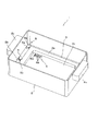
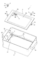
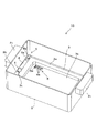
まず、図1〜図6により第1形態例を説明する。図1は本例の玉箱1の斜視図、図2は玉箱1の分解斜視図、図3は玉箱1の容量変更を説明する分解斜視図、図4は玉箱1の容量変更後の状態(後述する第2状態)を示す斜視図、図5(a)は玉箱1の平面図、図5(b)は玉箱1の断面図(図5(a)のX−X断面図)、図6(a)は容量変更後の玉箱1の平面図、図6(b)は容量変更後の玉箱1の断面図(図6(a)のY−Y断面図)である。図5(b)及び図6(b)では、断面のみを示している。
なお以下では、図5(a)や図6(a)の紙面における左方を左方とし、同紙面における右方を右方とし、同紙面における上方を前方とし、同紙面における下方を後方とし、同紙面に直交する方向を上下方向とする。
Embodiments of the present invention will be described below with reference to the drawings.
(First embodiment)
First, a first embodiment will be described with reference to FIGS. 1 is a perspective view of the
In the following, the left side in FIG. 5 (a) and FIG. 6 (a) is the left side, the right side in the page is the right side, the upper side in the page is the front, and the lower side in the page is the rear. The direction perpendicular to the paper surface is the up-down direction.
玉箱1は、図2に示すように、上方を開放する箱状に形成され、底部の中央部に中央開口2aを形成して周縁部を残した状態の基体2と、この基体2の周縁部2bの支持部2cに載置される載置部3aの内側に下方に窪む窪み部3bが形成された底板部材3と、底板部材3を基体2に止めるための止着部材4と、を有し、図3及び図4に示す如く底板部材3の上下を裏返して載置部3aを支持部2cに載せることにより、載置部3aの内側が上方に隆起した状態となることで容量を変更できる。
即ち玉箱1は、図1に示すように窪み部3b(載置部3aの内側)が下方に窪んだ状態で底板部材3が基体2に取り付けられた第1状態(容量が比較的多い状態)と、図4に示すように窪み部3bが上方に隆起した状態で底板部材3が基体2に取り付けられた第2状態(容量が比較的少ない状態)と、に変更可能である。しかもこの第1状態から第2状態への容量変更、或いは第2状態から第1状態への容量変更は、底板部材3の取付姿勢を単に裏返すことによって、可能である。なお本例の場合、第1状態での玉箱1は約2000個の遊技球が収納できる容量であり、第2状態での玉箱1は約1600個の遊技球が収納できる容量である。
As shown in FIG. 2, the
That is, as shown in FIG. 1, the
ここで止着部材4は、図2等に示すように、頭部4aと、頭部4aより同軸上に延びる軸部4bとよりなる。軸部4bは、先端が拡径して先端に拡径部4cが形成され、中央軸線上に先端から切り込みが入っていて先端側が二つに割れた構造となっている。頭部4aは、円盤状で、軸部4b(先端の拡径部を除く)よりも大径である。この止着部材4は、軸部4bの二つに割れた部分が内側に弾力的に撓むことで、自然状態にある先端の拡径部4cよりも小さい内径の所定の止着穴(頭部4aよりも小径の穴)に軸部4bを挿入可能であり、挿入後には拡径部4cが前記止着穴の裏側周囲に係合して抜けなくなる部材である(後述の図8(b)参照)。但し、例えば止着穴の裏側から軸部4bの先端の拡径部4cを指で挟むように内側に押しながら挿入時と反対方向に押せば、拡径部4cの係合を解除して容易に取り外すことができる。
Here, as shown in FIG. 2 and the like, the
次に基体2は、図2及び図5(a)に示すように、上面から見て基本的に左右方向に長い長方形状のものであり、短辺側の両側面(即ち左右両側面)の前後中央位置には、人が玉箱1を持つための取手2cが左右外側に突出するように設けられている。また基体2の底面の中央開口2aは、基体2の長方形状の底面に対して概略相似形になるように形成され、前述の周縁部2bは、基体2の底面における中央開口2aを除く部分であり、中央開口2aの周囲を囲むように形成されている。なお前述の支持部2cは、周縁部2bのうち、底板部材3の載置部3aが載置される部分である。
そして、この支持部2bにおける左右両辺部(短辺部)の中央には、止着部材4の軸部4bを挿入して係合させるための止着穴2dが形成されている。
また、基体2の周縁部2bにおける左右両辺部の一方の端であって、支持部2cの外側の位置には、第1の放電部5が設けられている。第1の放電部5は、遊技球が1個以上落ち込むことが可能なように下方に窪んだ凹部5aと、この凹部5aの底面に形成され上下に貫通する開口5bとよりなる。開口5bは、凹部5aに落ち込んだ遊技球の下部を基体2の下方に臨ませ得るものである。この構成によって第1の放電部5は、凹部5aに落ち込んだ遊技球の下部を島設備の膳板(通常ステンレス鋼板で被覆されている)等の導電体に接触させることによって、玉箱1内に収容した遊技球に帯電する電荷(静電気)を放出する機能を発揮する。なお第1の放電部5は、図5(a)に示すように、基体2の底面における対角線上の二つの隅に合計2個設けられている。
Next, as shown in FIG. 2 and FIG. 5A, the
A
A
次に底板部材3は、図2及び図5(a)に示すように、上面から見て基本的に左右方向に長い長方形板状のものであり、短辺側の両端(即ち左右両端)の前後中央位置には、止着用の突片3cが左右外側に突出するように形成されている。この突片3cには、止着部材4の軸部4bが貫通可能な貫通孔3d(止着部材4の頭部4aよりも小径なもの)が形成されている。
この底板部材3全体(突片3cを除く)の前後左右の大きさは、基体2の底面よりも小さく、基体2の中央開口2aよりも大きく設定されている。また、この底板部材3の周縁部として形成された前述の載置部3aは、既述したように、基体2の支持部2cの上に載置可能である。また、この底板部材3の載置部3aの内側に形成された窪み部3bは、上面から見て基体2の中央開口2aに対応した長方形状のものであり、前記中央開口2a内にはまり込むことが可能な大きさ(即ち前後左右の外径が中央開口2aよりも小さい寸法)とされている。
Next, as shown in FIG. 2 and FIG. 5A, the
The size of the entire bottom plate member 3 (excluding the projecting
そして図2に示すように、底板部材3の窪み部3bの底面における左前側の隅には、当該玉箱1の前記第1状態での概略容量を明示する明示部6が設けられている。また図3に示すように、底板部材3の窪み部3bの裏面における左後側の隅には、当該玉箱1の前記第2状態での概略容量を明示する明示部7が設けられている。
明示部6は、「2000」の「2」の文字がインクの塗布或いは文字形部材の貼り付け等によって形成された1個の文字部6aと、「2000」の「0」の文字を表す3個の開口6bと、が並んで設けられてなる。ここで、明示部6の開口6bは、底板部材3が窪み部3bを下方に窪ませている状態(即ち前記第1状態)において遊技球の下部を窪み部3bの下方に臨ませる得る開口であり、玉箱1に収容した遊技球に帯電する電荷を放出する第2の放電部を構成する。
明示部7は、「1600」の「1」の文字がインクの塗布或いは文字形部材の貼り付け等によって形成された1個の文字部7aと、「1600」の「6」の文字が同様に形成された1個の文字部7bと、「1600」の「0」の文字が同様に形成された2個の文字部7cと、が並んで設けられてなる。
As shown in FIG. 2, at the left front corner of the bottom surface of the recessed
The
The
以上の構成の玉箱1は、次のように容易に組立可能であり、また容易に容量変更が可能である。
即ち、図1及び図2に示すように、窪み部3bを下方に窪ませた状態(明示部6が形成された窪み部3bの底面が上面側から見える状態)で底板部材3を基体2の底面に配置し、窪み部3bを中央開口2a内にはめ込み、載置部3aを支持部2cの上に載置し、止着穴2dと貫通孔3dの位置を同軸上に合わせる。その後、止着部材4の軸部4bを貫通孔3dと止着穴2dに挿入し、軸部4b先端の拡径部4cを止着穴2dの裏側周囲に係合させて(後述の図8(b)参照)、止着部材4を左右2箇所にそれぞれ装着する。これによって、玉箱1は前述した第1状態(図1に示す)に組み立てられ、底板部材3は止着部材4の頭部4aで両側の突片3cを押さえられて上記配置状態に保持され、この第1状態が保持される。
The
That is, as shown in FIG. 1 and FIG. 2, the
そして、この第1状態にある玉箱1は、左右両側の止着部材4を既述した方法で取り外し、図3及び図4に示すように、底板部材3の上下を裏返し、窪み部3bを上方に隆起させた状態(明示部7が形成された窪み部3bの裏面が上面側から見える状態)で底板部材3を基体2の底面に配置し、載置部3aを支持部2cの上に載置し、止着穴2dと貫通孔3dの位置を同軸上に合わせる。その後、第1状態への組立と同様に、止着部材4を左右2箇所にそれぞれ装着する。これによって、玉箱1は第1状態から前述した第2状態(図4に示す)に組み替えられ、底板部材3は第1状態と同様に止着部材4で両側を押さえられて上記配置状態に保持され、この第2状態が保持される。
なお、逆の手順で第2状態から第1状態への組み替えも容易に可能なことはいうまでもなく、このようにして玉箱1は容易に容量変更が何度でも可能である。
Then, the
Needless to say, reversal from the second state to the first state can be easily performed in the reverse procedure, and the capacity of the
以上説明したように本例の玉箱1によれば、底板部材3が、載置部3aの内側(窪み部3b)を下方に窪ませている第1状態と、載置部3aの内側を上方に隆起させる第2状態と、に変換されて容量が変更できるので、玉箱の容量を変え得る部材(底板部材3)を玉箱本体(基体2)から取り外すことなく常に一体状態とできる。
また本例の玉箱1によれば、第1の放電部5或いはさらに開口6b(第2の放電部)によって遊技球に帯電する電荷を放出できる。しかも、容量の明示部6と放電部(第2の放電部)とが兼用でき、明示部と別個に放電部を形成する場合に比べて、底板部材3の金型製作が簡素になる。
As described above, according to the
Further, according to the
(第2形態例)
次に、図7,8により第2形態例を説明する。図7は本例の玉箱10の斜視図、図8(a)は玉箱10の平面図、図8(b)は玉箱10の断面図(図8(a)のZ−Z断面図)である。図8(b)では、断面のみを示している。
本第2形態例の玉箱10は、第1形態例における第1の放電部5に遊技球を誘導する誘導樋8を設けたことを特徴とする。第1形態例と同様の構成要素には同符号を使用して説明を省略する。誘導樋8は、図7,8に示すように、基体2の周縁部2bにおける左右両辺部(短辺部)の中央付近(即ち止着穴2d付近)から第1の放電部5の凹部5aまで延びるように形成された遊技球1個分以上に対応する幅の溝であり、前記中央付近から凹部5aに向かって底面が下り傾斜している。
本例であると、遊技球が誘導樋8の傾斜する底面を転動して第1の放電部5の凹部5a内に流入し易い。このため、第1の放電部5の凹部5a内に遊技球を確実に落とし込んで、遊技球に帯電する電荷を確実に放出できる。
(Second embodiment)
Next, a second embodiment will be described with reference to FIGS. 7 is a perspective view of the
The
In this example, the game ball rolls on the inclined bottom surface of the
なお、今回開示された実施の形態はすべての点で例示であって制限的なものではないと考えられるべきである。本発明の範囲は上記した説明ではなくて特許請求の範囲によって示され、特許請求の範囲と均等の意味及び範囲内でのすべての変更が含まれることが意図される。 The embodiment disclosed this time should be considered as illustrative in all points and not restrictive. The scope of the present invention is defined by the terms of the claims, rather than the description above, and is intended to include any modifications within the scope and meaning equivalent to the terms of the claims.
1,10 玉箱
2 基体
2a 中央開口
2b 周縁部
2c 支持部
3 底板部材
3a 載置部
3b 窪み部
5 第1の放電部
5b 開口
6,7 明示部
6b 開口(第2の放電部)
8 誘導樋
DESCRIPTION OF
8 Guide 樋
Claims (3)
前記周縁部の支持部に載置される載置部の内側に下方に窪む窪み部が形成された底板部材と、を有し、
前記底板部材の上下を裏返して載置部を支持部に載せることにより、載置部の内側の前記窪み部が下方に窪んだ第1状態と、前記窪み部が上方に隆起した第2状態とに変換可能であることを特徴とする玉箱。 A base that is formed in a box shape that opens upward, with the center of the bottom opened and the peripheral edge left,
A bottom plate member formed with a hollow portion recessed downward on the inner side of the placement portion placed on the support portion of the peripheral edge portion,
By turning the bottom plate member upside down and placing the mounting portion on the support portion, a first state in which the hollow portion inside the mounting portion is recessed downward, and a second state in which the hollow portion is raised upward A ball box characterized by being convertible to.
該明示部は、底板部材が前記載置部の内側を下方に窪ませている状態において遊技球の下部を窪み部の下方に臨ませる得る開口を形成することにより収容した遊技球に帯電する電荷を放出する第2の放電部を含むことを特徴とする請求項1または2に記載の玉箱。
The hollow portion is provided with an explicit portion that clearly indicates the approximate capacity of the ball box,
The manifestation portion is a charge that charges the game ball accommodated by forming an opening that allows the bottom plate member to face the lower portion of the game ball below the depression portion in a state where the inside of the placement portion is depressed downward. The ball box according to claim 1, further comprising: a second discharge part that discharges water.
Priority Applications (1)
| Application Number | Priority Date | Filing Date | Title |
|---|---|---|---|
| JP2008320478A JP4843018B2 (en) | 2008-12-17 | 2008-12-17 | Game machine |
Applications Claiming Priority (1)
| Application Number | Priority Date | Filing Date | Title |
|---|---|---|---|
| JP2008320478A JP4843018B2 (en) | 2008-12-17 | 2008-12-17 | Game machine |
Publications (2)
| Publication Number | Publication Date |
|---|---|
| JP2010142329A true JP2010142329A (en) | 2010-07-01 |
| JP4843018B2 JP4843018B2 (en) | 2011-12-21 |
Family
ID=42563389
Family Applications (1)
| Application Number | Title | Priority Date | Filing Date |
|---|---|---|---|
| JP2008320478A Expired - Fee Related JP4843018B2 (en) | 2008-12-17 | 2008-12-17 | Game machine |
Country Status (1)
| Country | Link |
|---|---|
| JP (1) | JP4843018B2 (en) |
Citations (6)
| Publication number | Priority date | Publication date | Assignee | Title |
|---|---|---|---|---|
| JPH1057613A (en) * | 1996-08-19 | 1998-03-03 | Ace Denken:Kk | Receptacle for game medium |
| JPH10165637A (en) * | 1996-12-10 | 1998-06-23 | Okumura Yuki Kk | Game medium container and game machine |
| JP2000126440A (en) * | 1998-10-22 | 2000-05-09 | Ever Prospect Internatl Ltd | Game medium container box |
| JP2001137529A (en) * | 1999-11-15 | 2001-05-22 | Nippon Pachinko Buhin Kk | Pachinko ball storage box |
| JP2005059898A (en) * | 2003-08-13 | 2005-03-10 | Toshikatsu Tazaki | Container |
| JP2005261472A (en) * | 2004-03-16 | 2005-09-29 | Aruze Corp | Game machine and game medium tray |
-
2008
- 2008-12-17 JP JP2008320478A patent/JP4843018B2/en not_active Expired - Fee Related
Patent Citations (6)
| Publication number | Priority date | Publication date | Assignee | Title |
|---|---|---|---|---|
| JPH1057613A (en) * | 1996-08-19 | 1998-03-03 | Ace Denken:Kk | Receptacle for game medium |
| JPH10165637A (en) * | 1996-12-10 | 1998-06-23 | Okumura Yuki Kk | Game medium container and game machine |
| JP2000126440A (en) * | 1998-10-22 | 2000-05-09 | Ever Prospect Internatl Ltd | Game medium container box |
| JP2001137529A (en) * | 1999-11-15 | 2001-05-22 | Nippon Pachinko Buhin Kk | Pachinko ball storage box |
| JP2005059898A (en) * | 2003-08-13 | 2005-03-10 | Toshikatsu Tazaki | Container |
| JP2005261472A (en) * | 2004-03-16 | 2005-09-29 | Aruze Corp | Game machine and game medium tray |
Also Published As
| Publication number | Publication date |
|---|---|
| JP4843018B2 (en) | 2011-12-21 |
Similar Documents
| Publication | Publication Date | Title |
|---|---|---|
| EP2259115A3 (en) | Optical fiber drop terminal | |
| JP2021176537A (en) | Aromatic container for automobile | |
| JP4843018B2 (en) | Game machine | |
| JP2008245997A (en) | Game machine | |
| JP2005296330A (en) | Golf tee | |
| KR102185870B1 (en) | Board game aparatus | |
| JP6343144B2 (en) | Floor power generation structure | |
| JP2005066329A5 (en) | ||
| JP3208841U (en) | Mahjong tile holder | |
| KR20110106614A (en) | Cup ejector | |
| JP2010119873A (en) | Symbol display device | |
| JP4007926B2 (en) | Optical fiber cord extra length storage tray | |
| JP2002143405A5 (en) | ||
| JP2004216140A5 (en) | ||
| JP3143596U (en) | Sudoku board | |
| KR200451762Y1 (en) | Decorative toys | |
| JP4533661B2 (en) | Game piece and game piece set | |
| KR100759534B1 (en) | Multistage golf tee | |
| KR200397224Y1 (en) | pasteboard card | |
| JP2002035406A (en) | 3d puzzle | |
| JP4753965B2 (en) | Bullet ball machine | |
| KR200272101Y1 (en) | Top | |
| JP4651097B2 (en) | Magic tool | |
| JP2020171598A (en) | Container with take-out tool | |
| JP4398045B2 (en) | Pachinko prize ball storage box |
Legal Events
| Date | Code | Title | Description |
|---|---|---|---|
| TRDD | Decision of grant or rejection written | ||
| A977 | Report on retrieval |
Free format text: JAPANESE INTERMEDIATE CODE: A971007 Effective date: 20110921 |
|
| A01 | Written decision to grant a patent or to grant a registration (utility model) |
Free format text: JAPANESE INTERMEDIATE CODE: A01 Effective date: 20110922 |
|
| A01 | Written decision to grant a patent or to grant a registration (utility model) |
Free format text: JAPANESE INTERMEDIATE CODE: A01 |
|
| A61 | First payment of annual fees (during grant procedure) |
Free format text: JAPANESE INTERMEDIATE CODE: A61 Effective date: 20111006 |
|
| R150 | Certificate of patent (=grant) or registration of utility model |
Free format text: JAPANESE INTERMEDIATE CODE: R150 |
|
| FPAY | Renewal fee payment (prs date is renewal date of database) |
Free format text: PAYMENT UNTIL: 20141014 Year of fee payment: 3 |
|
| FPAY | Renewal fee payment (prs date is renewal date of database) |
Free format text: PAYMENT UNTIL: 20141014 Year of fee payment: 3 |
|
| R250 | Receipt of annual fees |
Free format text: JAPANESE INTERMEDIATE CODE: R250 |
|
| LAPS | Cancellation because of no payment of annual fees |