JP2005296330A - Golf tee - Google Patents
Golf tee Download PDFInfo
- Publication number
- JP2005296330A JP2005296330A JP2004116889A JP2004116889A JP2005296330A JP 2005296330 A JP2005296330 A JP 2005296330A JP 2004116889 A JP2004116889 A JP 2004116889A JP 2004116889 A JP2004116889 A JP 2004116889A JP 2005296330 A JP2005296330 A JP 2005296330A
- Authority
- JP
- Japan
- Prior art keywords
- coil spring
- ball
- golf
- golf tee
- cylindrical
- Prior art date
- Legal status (The legal status is an assumption and is not a legal conclusion. Google has not performed a legal analysis and makes no representation as to the accuracy of the status listed.)
- Granted
Links
Images
Landscapes
- Golf Clubs (AREA)
- Springs (AREA)
Abstract
【課題】 ゴルフボールを打ったときの衝撃を吸収して破損や紛失を防ぎ、積み重なったコイルバネの接触面積が広いため、左右にずれにくくて、支持されるゴルフボールの位置ずれを防ぐことができ、すっきりした外観のゴルフティを提供すること。
【解決手段】 下端が先鋭状に形成された差込部1と、頂部に設けられたボール載置部2とをコイルバネ3で連結して成り、コイルバネ3は角形断面を有し、コイルバネ3の上下に積み重なった各段どうしが面接触している。
【選択図】 図2
PROBLEM TO BE SOLVED: To prevent damage or loss by absorbing an impact when a golf ball is hit, and because the contact area of stacked coil springs is wide, it is difficult to shift from side to side, and the position of a supported golf ball can be prevented from being displaced. To provide a golf tee with a clean appearance.
SOLUTION: An insertion portion 1 having a sharp lower end and a ball mounting portion 2 provided at the top are connected by a coil spring 3, and the coil spring 3 has a square cross section. The steps stacked up and down are in surface contact.
[Selection] Figure 2
Description
本発明は、ゴルフティに関する。 The present invention relates to a golf tee.
一般的に使用されていたゴルフティは、木、プラスチック等を素材として、先細の差込部とボール支持台とが一体に形成されていた。
このようなゴルフティは、硬質素材を用いているため、ゴルフクラブでゴルフボールを打った時に、クラブヘッドが当たった衝撃で変形したり、折れたり、或いは、遠くへはじき飛ばされて紛失することが多い。
Generally used golf tees are made of wood, plastic, or the like, and a tapered insertion portion and a ball support base are integrally formed.
Since such golf tees are made of a hard material, when a golf ball is hit with a golf club, it may be deformed or broken by the impact of the club head, or may be lost by being repelled far away. Many.
そこで、従来、クラブヘッドが衝突した衝撃を吸収し、破損や紛失を防ぐことができるゴルフティとして、1本の鋼鉄線をコイルバネ状に折り曲げて、皿状の載置部と、胴部と、埋設部とを連続して形成したスプリング式ゴルフティが提案されている(特許文献1参照)。
しかし、通常の鋼鉄線は断面が円形であるため、上下に重なったスプリングの各段が互いに線接触し、接触面積が非常に小さいので、不安定で左右にずれやすく、このため、ゴルフボールが位置ずれしやすい。また、地面に差し込む時及び引き抜く時にコイルバネを持つことになるので、外力によってコイルバネが変形しやすいという欠点がある。
Therefore, conventionally, as a golf tee that can absorb the impact of the collision of the club head and prevent breakage or loss, one steel wire is bent into a coil spring shape, a dish-shaped placement portion, a trunk portion, A spring-type golf tee in which an embedded portion is continuously formed has been proposed (see Patent Document 1).
However, since a normal steel wire has a circular cross section, the upper and lower spring stages are in line contact with each other, and the contact area is very small. Easily misaligned. Further, since the coil spring is held when being inserted into the ground and pulled out, there is a drawback that the coil spring is easily deformed by an external force.
さらに、埋設部とボール支持部とをコイルバネ連結すると共に、埋設部とボール支持部とを凹凸嵌合したゴルフティが知られている(特許文献2及び特許文献3参照)。
このゴルフティでは、埋設部とボール支持部とが凹凸嵌合によって正確な位置に位置決めされているので、ゴルフボールが安定して支持され、位置ずれしにくい。
しかし、ゴルフボールを打って、ボール支持部が埋設部から外れると、その都度、人手によってボール支持部と埋設部とを嵌合し直さなければならず、この作業が非常に面倒である。
Further, there is known a golf tee in which an embedded portion and a ball support portion are connected by a coil spring, and the embedded portion and the ball support portion are concavo-convexly fitted (see
In this golf tee, since the embedded portion and the ball support portion are positioned at an accurate position by the concave-convex fitting, the golf ball is stably supported and is not easily displaced.
However, every time the golf ball is hit and the ball support portion is detached from the embedded portion, the ball support portion and the embedded portion must be re-fitted manually, which is very troublesome.
本発明が解決しようとする課題は、ゴルフボールを打ったときの衝撃を吸収して、破損や紛失を防ぎ、打撃後はボール載置部が差込部に対して自動的に元の位置に復帰し、積み重なったコイルバネの各段どうしの接触面積が広いため、左右にずれにくくて、ゴルフボールの位置ずれを防ぐことができ、すっきりした外観のゴルフティを提供することにある。 The problem to be solved by the present invention is to absorb impact when a golf ball is hit to prevent breakage or loss, and after hitting, the ball mounting portion is automatically returned to its original position with respect to the insertion portion. An object of the present invention is to provide a golf tee having a neat appearance, because the contact area between the steps of the coil springs that have been restored and stacked is large, and thus it is difficult to shift to the left and right, can prevent the golf ball from being displaced.
本発明のゴルフティは、下端が先鋭状に形成された差込部と、頂部に設けられたボール載置部とをコイルバネで連結して成り、前記コイルバネは角形断面を有し、コイルバネの上下に積み重なった各段どうしが面接触している。
前記差込部の上端部に、上端面が開口した筒状頭部を形成し、前記ボール載置部の下端部に、下端面が開口した筒状支持部を形成し、前記コイルバネの両端部を、それぞれ前記筒状頭部及び筒状支持部に挿入して固定しても良い。
The golf tee of the present invention is formed by connecting an insertion portion having a sharp lower end and a ball mounting portion provided at the top with a coil spring, the coil spring having a square cross section, and The steps stacked in contact with each other are in surface contact.
A cylindrical head portion having an open upper end surface is formed at the upper end portion of the insertion portion, and a cylindrical support portion having an open lower end surface is formed at the lower end portion of the ball mounting portion, and both end portions of the coil spring are formed. May be inserted into and fixed to the cylindrical head and the cylindrical support, respectively.
請求項1に係る発明によれば、ボール載置部に載置されたゴルフボールをゴルフクラブで打つと、コイルバネが撓んでその衝撃を吸収するので、破損したり遠くへ飛んで紛失するのを防ぐことができ、ゴルフボールを打った衝撃でボール載置部の位置がずれても、コイルバネの復元力で、自動的に元の位置に復帰する。
また、コイルバネの積み重なった各段は面接触しているので、接触面積が広くて左右に位置ずれしにくく、この結果、ゴルフボールを正しい位置に安定して支持することができる。
さらに、コイルバネは、断面円形のコードを巻いたものに比べて、外面の凹凸が少なく平滑になるため、外観がすっきりする。
According to the first aspect of the present invention, when a golf ball placed on the ball placement portion is hit with a golf club, the coil spring is bent and absorbs the impact. Even if the position of the ball mounting portion is shifted due to the impact of hitting the golf ball, it is automatically returned to the original position by the restoring force of the coil spring.
Further, since the stacked stages of the coil springs are in surface contact, the contact area is large and the position is hardly displaced left and right, and as a result, the golf ball can be stably supported at the correct position.
Furthermore, since the coil spring has less irregularities on the outer surface and is smoother than that of a coil wound with a circular cross-section, the appearance is clear.
請求項2に係る発明によれば、衝撃吸収力の高い比較的長いコイルバネで差込部とボール載置部とを連結しても、左右にぐらつきにくいため、いっそう安定してゴルフボールを支持することが可能となる。
また、常態においては、差込部を地面に差し込んだり引き抜く際に、筒状頭部を持つことができ、コイルバネに外力が加わらないので、正確な方向に差し込むことができると共に、長期間使用してもコイルバネが変形しにくい。
According to the second aspect of the present invention, even if the insertion portion and the ball placement portion are connected with a relatively long coil spring having a high impact absorption capability, the golf ball is more stably supported because it is less likely to wobble from side to side. It becomes possible.
Also, under normal conditions, when inserting or pulling out the insertion part, it can have a cylindrical head, and since no external force is applied to the coil spring, it can be inserted in the correct direction and used for a long time. However, the coil spring is difficult to deform.
以下、本発明の実施例を図面に基づいて詳細に説明する。
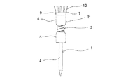
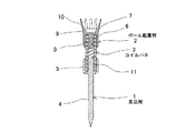
図1及び図2に示すように、本発明のゴルフティは、差込部1とボール載置部2とをコイルバネ3で連結して成る。
差込部1は、合成樹脂、金属等を素材とし、下端が先鋭状のピン体4と、ピン体4の上端に一体に形成された筒状頭部5とを備える。筒状頭部5は、ピン体4より径大で、上端面が開口した円筒体より成り、ピン体4と中心軸を共有するよう形成されている。
また、筒状頭部5の上面(開口底面)中心から上方に向かって、中心軸に沿う下部突起11が一体に突設されている。
Hereinafter, embodiments of the present invention will be described in detail with reference to the drawings.
As shown in FIGS. 1 and 2, the golf tee of the present invention is formed by connecting an
The
Further, a
ボール載置部2は、合成樹脂、金属等を素材とし、筒状支持部6と、ボール支持台7とを備える。
筒状支持部6は、筒状頭部5と同径で下端面が開口した円筒体より成り、その下面(開口天面)中心から下方に向かって、中心軸に沿う上部突起8が一体に形成されている。
ボール支持台7は、ボール載置部2と一体に形成され、環状部9の上端縁に多数の支持片10を設けて成る。
支持片10は、上部が径方向外方へ傾斜しており、上部が下部よりやや細く形成され、環状部9の周方向に等間隔で立設されている。即ち、環状に配置された支持片10によって、上方へラッパ状に開いたボール受け部分が形成される。
The
The
The
The upper part of the
コイルバネ3は、合成樹脂製で断面角形のコードを螺旋状に巻いたものであり、その外径は筒状頭部5及び筒状支持部6の内径よりもやや小さく形成されている。
また、コイルバネ3は角形断面を有するので、コイルバネ3の上下に積み重なった各段どうしは、広い面積で面接触している。従って、コイルバネ3の外面は、円形断面のコードを巻いたコイルバネに比べて平滑になり、外観がすっきりする。
さらに、コイルバネ3の両端部は、それぞれ筒状頭部5及び筒状支持部6内へ挿入されて、下部突起11及び上部突起8の外周に嵌合されて固定されている。
The
Further, since the
Further, both end portions of the
このゴルフティを使用する際は、筒状頭部5を持って差込部1を地面へ差し込み、ボール載置部2の上にゴルフボールを載せる。ボール載置部2上に支持されたゴルフボールをゴルフクラブで打つと、ゴルフクラブが当たった衝撃でコイルバネ3が撓み、ボール載置部2が移動する。
しかし、外力が消失すると、コイルバネ3の復元力によってボール載置部2は、自動的に差込部1の直上である元の位置に復帰する。
また、ゴルフティを引き抜く際も、筒状頭部5を持てば、コイルバネ3に外力が加わることはない。
When using this golf tee, the
However, when the external force disappears, the
Also, when pulling out the golf tee, if the
1 差込部
2 ボール載置部
3 コイルバネ
4 ピン体
5 筒状頭部
6 筒状支持部
7 ボール支持台
8 上部突起
9 環状部
10 支持片
11 下部突起
DESCRIPTION OF
Claims (2)
A cylindrical head portion having an open upper end surface is formed at the upper end portion of the insertion portion, and a cylindrical support portion having an open lower end surface is formed at the lower end portion of the ball mounting portion, and both end portions of the coil spring are formed. The golf tee according to claim 1, wherein each of the golf tees is inserted and fixed in the cylindrical head and the cylindrical support.
Priority Applications (1)
| Application Number | Priority Date | Filing Date | Title |
|---|---|---|---|
| JP2004116889A JP4382563B2 (en) | 2004-04-12 | 2004-04-12 | Golf tee |
Applications Claiming Priority (1)
| Application Number | Priority Date | Filing Date | Title |
|---|---|---|---|
| JP2004116889A JP4382563B2 (en) | 2004-04-12 | 2004-04-12 | Golf tee |
Publications (2)
| Publication Number | Publication Date |
|---|---|
| JP2005296330A true JP2005296330A (en) | 2005-10-27 |
| JP4382563B2 JP4382563B2 (en) | 2009-12-16 |
Family
ID=35328591
Family Applications (1)
| Application Number | Title | Priority Date | Filing Date |
|---|---|---|---|
| JP2004116889A Expired - Lifetime JP4382563B2 (en) | 2004-04-12 | 2004-04-12 | Golf tee |
Country Status (1)
| Country | Link |
|---|---|
| JP (1) | JP4382563B2 (en) |
Cited By (11)
| Publication number | Priority date | Publication date | Assignee | Title |
|---|---|---|---|---|
| USD543597S1 (en) * | 2006-03-15 | 2007-05-29 | Sung-Eun Lee | Golf tee |
| USD555218S1 (en) * | 2007-01-22 | 2007-11-13 | Hyung Choon Lee | Golf tee |
| USD566802S1 (en) * | 2007-01-23 | 2008-04-15 | Francis Carroll | Golf tee |
| JP2010516391A (en) * | 2007-01-23 | 2010-05-20 | グリーンキーパーズ・オブ・デラウェア・エルエルシー | Golf tee with rigid pile and flexible head |
| USD696365S1 (en) * | 2012-06-20 | 2013-12-24 | Koviss Sports Co., Ltd. | Golf tee |
| USD715877S1 (en) | 2014-03-04 | 2014-10-21 | Greenkeepers, Inc. | Golf tee |
| USD724685S1 (en) | 2013-12-27 | 2015-03-17 | Greenkeepers, Inc. | Counterweight for golf club |
| US9216337B2 (en) | 2014-01-31 | 2015-12-22 | Green Keepers, Inc. | Overmolded golf tee and method of making it |
| USD774606S1 (en) * | 2013-03-13 | 2016-12-20 | Green Keepers, Inc. | Golf tee |
| USD782587S1 (en) | 2015-12-04 | 2017-03-28 | Green Keepers, Inc. | Golf tee |
| US9849360B2 (en) | 2015-12-04 | 2017-12-26 | Greenkeepers, Inc. | Golf tee with ball support |
-
2004
- 2004-04-12 JP JP2004116889A patent/JP4382563B2/en not_active Expired - Lifetime
Cited By (12)
| Publication number | Priority date | Publication date | Assignee | Title |
|---|---|---|---|---|
| USD543597S1 (en) * | 2006-03-15 | 2007-05-29 | Sung-Eun Lee | Golf tee |
| USD555218S1 (en) * | 2007-01-22 | 2007-11-13 | Hyung Choon Lee | Golf tee |
| USD566802S1 (en) * | 2007-01-23 | 2008-04-15 | Francis Carroll | Golf tee |
| JP2010516391A (en) * | 2007-01-23 | 2010-05-20 | グリーンキーパーズ・オブ・デラウェア・エルエルシー | Golf tee with rigid pile and flexible head |
| US9381413B2 (en) | 2007-01-23 | 2016-07-05 | Greenkeepers Of Delaware, Llc | Golf tee with rigid stake and flexible crown |
| USD696365S1 (en) * | 2012-06-20 | 2013-12-24 | Koviss Sports Co., Ltd. | Golf tee |
| USD774606S1 (en) * | 2013-03-13 | 2016-12-20 | Green Keepers, Inc. | Golf tee |
| USD724685S1 (en) | 2013-12-27 | 2015-03-17 | Greenkeepers, Inc. | Counterweight for golf club |
| US9216337B2 (en) | 2014-01-31 | 2015-12-22 | Green Keepers, Inc. | Overmolded golf tee and method of making it |
| USD715877S1 (en) | 2014-03-04 | 2014-10-21 | Greenkeepers, Inc. | Golf tee |
| USD782587S1 (en) | 2015-12-04 | 2017-03-28 | Green Keepers, Inc. | Golf tee |
| US9849360B2 (en) | 2015-12-04 | 2017-12-26 | Greenkeepers, Inc. | Golf tee with ball support |
Also Published As
| Publication number | Publication date |
|---|---|
| JP4382563B2 (en) | 2009-12-16 |
Similar Documents
| Publication | Publication Date | Title |
|---|---|---|
| JP4382563B2 (en) | Golf tee | |
| US7815529B2 (en) | Adjustable golf tee assembly | |
| JP4216207B2 (en) | Golf tee attachment | |
| JP2003275356A (en) | Golf tee | |
| US8092321B2 (en) | Golf tee with a connecting wire and manufacturing method thereof | |
| JP2007330774A (en) | Golf tee | |
| KR100632769B1 (en) | Golf tees | |
| KR100730023B1 (en) | Golf tees and manufacturing method thereof | |
| KR200339017Y1 (en) | Golf tee of magnetic | |
| US20090176606A1 (en) | Tennis ball retriever | |
| US20070219022A1 (en) | Combined golf tee | |
| KR200440402Y1 (en) | Golf tee | |
| US20070010345A1 (en) | Golf ball retrieval device | |
| WO2005075029A1 (en) | Tee | |
| US6666339B2 (en) | Ball display assembly | |
| KR100538741B1 (en) | Damage and loss prevention golf tee | |
| JP3967686B2 (en) | Golf tee | |
| KR200458691Y1 (en) | Apparatus for supporting a batting ball | |
| JP3249876U (en) | Golf Tee | |
| GB2366210A (en) | Resilient tee device | |
| JP3113265U (en) | tea | |
| JP4502935B2 (en) | Golf tee | |
| KR200365547Y1 (en) | Golf tee | |
| JP3164074U (en) | Golf tee | |
| KR102734710B1 (en) | Clip for ball marker |
Legal Events
| Date | Code | Title | Description |
|---|---|---|---|
| A621 | Written request for application examination |
Free format text: JAPANESE INTERMEDIATE CODE: A621 Effective date: 20070223 |
|
| TRDD | Decision of grant or rejection written | ||
| A01 | Written decision to grant a patent or to grant a registration (utility model) |
Free format text: JAPANESE INTERMEDIATE CODE: A01 Effective date: 20090915 |
|
| A01 | Written decision to grant a patent or to grant a registration (utility model) |
Free format text: JAPANESE INTERMEDIATE CODE: A01 |
|
| A61 | First payment of annual fees (during grant procedure) |
Free format text: JAPANESE INTERMEDIATE CODE: A61 Effective date: 20090917 |
|
| FPAY | Renewal fee payment (event date is renewal date of database) |
Free format text: PAYMENT UNTIL: 20121002 Year of fee payment: 3 |
|
| R150 | Certificate of patent or registration of utility model |
Ref document number: 4382563 Country of ref document: JP Free format text: JAPANESE INTERMEDIATE CODE: R150 Free format text: JAPANESE INTERMEDIATE CODE: R150 |
|
| FPAY | Renewal fee payment (event date is renewal date of database) |
Free format text: PAYMENT UNTIL: 20121002 Year of fee payment: 3 |
|
| FPAY | Renewal fee payment (event date is renewal date of database) |
Free format text: PAYMENT UNTIL: 20151002 Year of fee payment: 6 |
|
| R250 | Receipt of annual fees |
Free format text: JAPANESE INTERMEDIATE CODE: R250 |
|
| R250 | Receipt of annual fees |
Free format text: JAPANESE INTERMEDIATE CODE: R250 |
|
| R250 | Receipt of annual fees |
Free format text: JAPANESE INTERMEDIATE CODE: R250 |
|
| R250 | Receipt of annual fees |
Free format text: JAPANESE INTERMEDIATE CODE: R250 |
|
| R250 | Receipt of annual fees |
Free format text: JAPANESE INTERMEDIATE CODE: R250 |
|
| R250 | Receipt of annual fees |
Free format text: JAPANESE INTERMEDIATE CODE: R250 |
|
| R250 | Receipt of annual fees |
Free format text: JAPANESE INTERMEDIATE CODE: R250 |
|
| R250 | Receipt of annual fees |
Free format text: JAPANESE INTERMEDIATE CODE: R250 |
|
| EXPY | Cancellation because of completion of term |