JP2010142291A - Game machine - Google Patents
Game machine Download PDFInfo
- Publication number
- JP2010142291A JP2010142291A JP2008320021A JP2008320021A JP2010142291A JP 2010142291 A JP2010142291 A JP 2010142291A JP 2008320021 A JP2008320021 A JP 2008320021A JP 2008320021 A JP2008320021 A JP 2008320021A JP 2010142291 A JP2010142291 A JP 2010142291A
- Authority
- JP
- Japan
- Prior art keywords
- push button
- button
- supported
- game
- supporting
- Prior art date
- Legal status (The legal status is an assumption and is not a legal conclusion. Google has not performed a legal analysis and makes no representation as to the accuracy of the status listed.)
- Granted
Links
- 238000003825 pressing Methods 0.000 claims abstract description 21
- 230000002093 peripheral effect Effects 0.000 claims description 21
- 230000002950 deficient Effects 0.000 abstract 2
- 230000007257 malfunction Effects 0.000 abstract 2
- 230000000694 effects Effects 0.000 description 10
- 238000010079 rubber tapping Methods 0.000 description 6
- 239000007858 starting material Substances 0.000 description 6
- 239000011521 glass Substances 0.000 description 5
- 238000009987 spinning Methods 0.000 description 4
- 238000001514 detection method Methods 0.000 description 3
- NJPPVKZQTLUDBO-UHFFFAOYSA-N novaluron Chemical compound C1=C(Cl)C(OC(F)(F)C(OC(F)(F)F)F)=CC=C1NC(=O)NC(=O)C1=C(F)C=CC=C1F NJPPVKZQTLUDBO-UHFFFAOYSA-N 0.000 description 3
- 239000000758 substrate Substances 0.000 description 3
- 238000005034 decoration Methods 0.000 description 2
- 238000005286 illumination Methods 0.000 description 2
- 238000004519 manufacturing process Methods 0.000 description 2
- 230000000149 penetrating effect Effects 0.000 description 2
- 230000000007 visual effect Effects 0.000 description 2
- 125000002066 L-histidyl group Chemical group [H]N1C([H])=NC(C([H])([H])[C@](C(=O)[*])([H])N([H])[H])=C1[H] 0.000 description 1
- 238000007599 discharging Methods 0.000 description 1
- 238000000605 extraction Methods 0.000 description 1
- 230000001788 irregular Effects 0.000 description 1
- 239000004973 liquid crystal related substance Substances 0.000 description 1
- 238000000034 method Methods 0.000 description 1
- 238000000465 moulding Methods 0.000 description 1
- 230000002265 prevention Effects 0.000 description 1
- 239000011347 resin Substances 0.000 description 1
- 229920005989 resin Polymers 0.000 description 1
- 238000005096 rolling process Methods 0.000 description 1
Images
Landscapes
- Pinball Game Machines (AREA)
- Slot Machines And Peripheral Devices (AREA)
Abstract
Description
本発明は、パチンコ機やスロットマシン等の遊技機に係り、詳しくは、遊技に応じて押圧操作される押しボタン装置の動作性能を改善した遊技機に関する。 The present invention relates to a gaming machine such as a pachinko machine or a slot machine, and more particularly to a gaming machine with improved operational performance of a push button device that is pressed according to a game.
一般に、遊技機、例えばパチンコ機として、球受け皿に滞留している遊技球が、発射ハンドルの操作に応じて遊技盤の遊技領域に打ち出された後、遊技領域の障害釘や風車等に導かれつつ盤面を流下して、各種入賞口に入球し、或いは入球せずに遊技領域下部のアウト口に流入するように構成されたものが知られている(特許文献1参照)。 Generally, as a game machine, for example, a pachinko machine, a game ball staying in a ball tray is launched into the game area of the game board according to the operation of the launch handle, and then led to obstacle nails or windmills in the game area. However, it is known that the player is configured to flow down the board surface to enter various winning holes or to flow into the outlets at the lower part of the game area without entering (see Patent Document 1).
このようなパチンコ機では、一般入賞口に入球した際にはそれに対応した個数の遊技球が払い出され、また始動チャッカーに入球した際にはこれに基づいて当たり/外れや演出パターンの抽選が行われると共に所定数の遊技球が払い出される。この抽選結果に基づき選定された演出パターンに応じて、例えば遊技盤の中央部分に設けられた液晶表示画面や各種の照明装置を介した視覚的表現、スピーカを介した聴覚的表現などを用い、様々な演出が行われる。なお、当たり(以下、「大当たり」ともいう)の発生時には、アタッカーと呼ばれる大入賞口が開放し、入球に対応して多量の遊技球が払い出される遊技者に有利な遊技状態となる。 In such a pachinko machine, when entering the general winning opening, a corresponding number of game balls are paid out, and when entering the starting chucker, the hit / miss or performance pattern is based on this. A lottery is performed and a predetermined number of game balls are paid out. Depending on the production pattern selected based on this lottery result, for example, using a liquid crystal display screen provided in the center part of the game board, visual expression through various illumination devices, auditory expression through a speaker, etc. Various productions are performed. When a win (hereinafter also referred to as “big hit”) occurs, a big winning opening called an attacker is opened, and a gaming state advantageous to a player to which a large amount of gaming balls are paid out in response to the winning is brought about.
また、遊技機、例えばスロットマシンとして、複数種の絵柄からなるシンボルマークを円周方向に多数(通常は21個)備えた横3列の回胴リールを、スタートレバー操作に基づいて回転させた後、3個のストップボタンを夫々押圧操作することで、各ボタンに対応する回胴リールを順次停止させて、各回胴リールに備えたシンボルマークのうちの所定の絵柄同士が一致したときに当たりとなり、ボーナス取得として多数の遊技メダルがメダル受け皿に放出される構造のものが知られている(特許文献2参照)。当該スロットマシンでは、主基板に装着されたROMの抽選機能により役抽選を行い、該対応役の結果に応じて回胴リールを停止制御させてシンボルマークを揃える際等に視覚的な演出を行っている。 Further, as a gaming machine, for example, a slot machine, a horizontal three-row spinning reel provided with a large number (usually 21) of symbol marks composed of a plurality of kinds of patterns in the circumferential direction was rotated based on a start lever operation. After that, by pressing each of the three stop buttons, the spinning reels corresponding to each button are sequentially stopped, and it is a hit when predetermined symbols of the symbol marks provided on the spinning reels match each other. As a bonus acquisition, a structure in which a large number of game medals are released to a medal tray is known (see Patent Document 2). In the slot machine, a lottery function is performed by the lottery function of the ROM mounted on the main board, and a visual presentation is performed when the reel reels are controlled to stop according to the result of the corresponding role to align the symbol marks. ing.
上述したようなパチンコ機やスロットマシンは、それぞれ遊技場(所謂ホール)内の遊技島と呼ばれる区域において、一方向に延在するランプ板や幕板に沿って列状に順次隣接した形で複数が配置されている。このように、多数の遊技機が整列した遊技島を多数備えた遊技場内の遊技島設備において、遊技者は、好みの遊技機に対面して着座し、パチンコ機或いはスロットマシン固有の遊技手法に沿って遊技を進める。 A plurality of pachinko machines and slot machines as described above are sequentially adjacent to each other in a row along ramp plates and curtain plates extending in one direction in an area called a game island in a game hall (so-called hall). Is arranged. In this way, in the game island equipment in the game hall having a large number of game islands in which a large number of game machines are arranged, the player sits facing the favorite game machine and uses a game technique unique to a pachinko machine or slot machine. Proceed along the game.
ところで、上述したようなスロットマシンでは、ストップボタンやベットボタン等の押しボタン装置において、押しボタンが操作時にボタン穴の内部に押し込まれたままの状態となり元の位置に復帰できなくなるといった不具合を生じることがあった。当該不具合は、遊技機本体側のボタンベースの樹脂成型時に上記ボタン穴の開口径が小さく成型されて、該ボタン穴と押しボタンとの間の間隙が小さくなることが一因である。そして、ボタン穴の内周面と押しボタンの外周面との間の間隙が小さくなった場合に、押しボタンが回転してねじ込まれてボタン穴に押し込まれ、押しボタンの中心に関して点対称の二位置にてボタン穴と押しボタンとが広い幅で面状に接触し、この際に各部品が面状に接触することで部品相互間の接触摩擦抵抗が増加し、押しボタンがボタン穴に挿入されたままの状態となる。 By the way, in the slot machine as described above, in a push button device such as a stop button or a bet button, there is a problem that the push button remains pushed into the button hole during operation and cannot be returned to the original position. There was a thing. The problem is partly because the opening diameter of the button hole is formed small during resin molding of the button base on the gaming machine main body side, and the gap between the button hole and the push button is reduced. Then, when the gap between the inner peripheral surface of the button hole and the outer peripheral surface of the push button becomes small, the push button rotates and is screwed into the button hole, and is point-symmetric with respect to the center of the push button. At the position, the button hole and the push button come into contact with each other with a wide width. At this time, each part comes into contact with the surface to increase the contact friction resistance between the parts, and the push button is inserted into the button hole. It will be in the state that has been done.
そこで従来、押しボタンがボタン穴にねじ込まれても、ボタン穴の内周面と押しボタンの外周面とを突起を介して接触させることで、ボタン穴と押しボタンとを少ない面積で接触させるように構成して各部品間の接触摩擦抵抗を減少させ、押しボタンの復帰不良の発生を軽減し得るようにした遊技機の操作スイッチが提案されている(特許文献3参照)。 Therefore, conventionally, even if the push button is screwed into the button hole, the button hole and the push button are brought into contact with each other with a small area by contacting the inner peripheral surface of the button hole and the outer peripheral surface of the push button through the protrusion. There has been proposed an operation switch for a gaming machine that is configured to reduce contact frictional resistance between components and reduce occurrence of push button return failure (see Patent Document 3).
上記特許文献3記載の遊技機の操作スイッチでは、押圧操作されて一定方向に摺動する押しボタンを収容するボタン穴が、その内周面に該押しボタンの外周面を当接させ且つ該押しボタンの摺動方向を案内するように構成され、該押しボタンの外周面には、ボタン穴と押しボタンとの間の間隙に突出する4個のリブが形成されている。このような構成により、押しボタンがボタン穴にねじ込まれた場合であっても、ボタン穴の内周面と押しボタンの外周面とがリブを介して接触することで、ボタン穴と押しボタンとを少ない面積で接触させ、ボタン穴を形成するボタンベースと押しボタンとの間の接触摩擦抵抗を減少して、押しボタンの復帰不良の発生を軽減し得る。 In the operation switch of the gaming machine described in Patent Document 3, a button hole that accommodates a push button that is pressed and slides in a certain direction has the outer peripheral surface of the push button in contact with the inner peripheral surface and the push button is pressed. The rib is configured to guide the sliding direction of the button, and four ribs are formed on the outer peripheral surface of the push button so as to protrude into the gap between the button hole and the push button. With such a configuration, even when the push button is screwed into the button hole, the inner surface of the button hole and the outer surface of the push button are in contact with each other through the rib, so that the button hole and the push button Can be contacted in a small area, and the contact frictional resistance between the button base forming the button hole and the push button can be reduced, thereby reducing the occurrence of a return failure of the push button.
しかしながら、上述した特許文献3記載の操作スイッチによると、押しボタンがボタン穴にねじ込まれた場合に、間隙に突出する4個のリブがボタン穴の内周面に接触することで接触摩擦抵抗の低減を可能にするものの、押しボタンが斜めに強く押し込まれた際には、4個のリブがボタン穴の内周面で食い込み、押しボタンの復帰不良を生じる等、動作が安定しない虞がある。 However, according to the operation switch described in Patent Document 3 described above, when the push button is screwed into the button hole, the four ribs protruding into the gap come into contact with the inner peripheral surface of the button hole, thereby reducing the contact friction resistance. Although it can be reduced, when the push button is pushed strongly diagonally, the four ribs bite in the inner peripheral surface of the button hole, and the push button may not return properly. .
そこで本発明は、接触摩擦抵抗を減少させて押しボタンの復帰不良の発生を大幅に軽減できるものでありながら、従来のように4個のリブがボタン穴の内周面で食い込むような不具合を無くして、動作性能を向上させ得るように構成した遊技機を提供することを目的とする。 Therefore, the present invention can greatly reduce the occurrence of push button reset failure by reducing the contact frictional resistance, but has a problem that the four ribs bite in the inner peripheral surface of the button hole as in the prior art. An object of the present invention is to provide a gaming machine that is configured so that the operation performance can be improved without it.
請求項1に係る本発明は(例えば図1ないし図9参照)、遊技に応じて押圧操作される押しボタン装置(50)を備える遊技機(1)において、
前記押しボタン装置(50)は、押圧操作される押しボタン部(54)と、該押しボタン部(54)をその押圧方向(例えば図4の上下方向)にて摺動自在に支持する摺動支持部(64a,65e)と、前記押しボタン部(54)を前記押圧方向と逆の方向に付勢する付勢手段(58)と、を有し、
前記摺動支持部は、前記押圧方向にて互いに離間した二箇所に設けられた支持面(64a,65e)を有し、かつ該二箇所の支持面により前記押しボタン部(54)を摺動自在に案内支持してなる、
ことを特徴とする遊技機(1)にある。
The present invention according to claim 1 (see, for example, FIG. 1 to FIG. 9) is a gaming machine (1) including a push button device (50) that is pressed according to a game.
The push button device (50) includes a push button portion (54) to be pressed, and a slide that slidably supports the push button portion (54) in the pressing direction (eg, the vertical direction in FIG. 4). A support portion (64a, 65e), and a biasing means (58) for biasing the push button portion (54) in a direction opposite to the pressing direction,
The sliding support portion has support surfaces (64a, 65e) provided at two locations separated from each other in the pressing direction, and the push button portion (54) is slid by the two support surfaces. Freely guide and support,
The gaming machine (1) is characterized by this.
請求項2に係る本発明は(例えば図4、図7及び図8参照)、前記押しボタン部(54)は、前記二箇所の支持面(64a,65e)にてそれぞれ摺動支持される二箇所の被支持面(55b,57f)を有し、かつ、
前記二箇所の支持面(64a,65e)を合わせた長さ(d5+d6)は、前記二箇所の被支持面(55b,57f)を合わせた長さ(d3+d4)に比して短い寸法に設定されてなる、
請求項1記載の遊技機(1)にある。
According to the second aspect of the present invention (see, for example, FIGS. 4, 7, and 8), the push button portion (54) is slidably supported by the two support surfaces (64a, 65e). Having a supported surface (55b, 57f) at a location, and
The combined length (d 5 + d 6 ) of the two supporting surfaces (64a, 65e) is compared with the combined length (d 3 + d 4 ) of the two supported surfaces (55b, 57f). Is set to a short dimension,
A gaming machine (1) according to
請求項3に係る本発明は(例えば図4、図7及び図8参照)、前記摺動支持部(64a,65e)は、前記押しボタン部(54)の外周面をその全域に亘って取り囲むように形成されてなる、
請求項1又は2記載の遊技機(1)にある。
According to the third aspect of the present invention (see, for example, FIGS. 4, 7, and 8), the sliding support portion (64a, 65e) surrounds the entire outer peripheral surface of the push button portion (54). Formed as
A gaming machine (1) according to
なお、上記カッコ内の符号は、図面と対照するためのものであるが、これは、発明の理解を容易にするための便宜的なものであり、特許請求の範囲の記載に何等影響を及ぼすものではない。 Note that the reference numerals in the parentheses are for comparison with the drawings, but this is for convenience to facilitate understanding of the invention and has no influence on the description of the claims. It is not a thing.
請求項1に係る本発明によると、押しボタン装置における押しボタン部をその押圧方向にて摺動自在に支持する摺動支持部が、押圧方向にて互いに離間した二箇所に設けられた支持面を有し、かつ該二箇所の支持面により押しボタン部を摺動自在に案内支持するので、互いに離れた二箇所の支持面にて押しボタン部を面接触支持することで、押しボタン部の外周面全体を摺動支持する場合に比して摩擦抵抗を大幅に低減しながら、安定に支持して耐久性を高めることができる。また、斜め押しされた場合であっても、傾いた押しボタン部を、押圧方向で離れた位置の2つの支持面により安定して案内支持できるので、押しボタン部が食い込んで復帰不良を生じるような不具合の発生を可及的に減少させることができる。 According to the first aspect of the present invention, the support surfaces provided at two locations where the sliding support portions for supporting the push button portion in the push button device so as to be slidable in the pressing direction are separated from each other in the pressing direction. Since the push button portion is slidably guided and supported by the two support surfaces, the push button portion is supported by surface contact with the two support surfaces separated from each other. Compared to the case where the entire outer peripheral surface is slidably supported, the frictional resistance is greatly reduced, and the durability can be enhanced by stably supporting. In addition, even when the button is pushed obliquely, the tilted push button part can be stably guided and supported by the two support surfaces separated in the pressing direction, so that the push button part bites in and causes a return failure. The occurrence of troubles can be reduced as much as possible.
請求項2に係る本発明によると、押しボタン部が、二箇所の支持面にてそれぞれ摺動支持される二箇所の被支持面を有し、二箇所の支持面を合わせた長さが、二箇所の被支持面を合わせた長さに比して短い寸法に設定されるので、比較的短い二箇所の支持面によって押しボタン部の二箇所の被支持面をそれぞれ安定に摺動支持できることで、面接触しながらも接触摩擦抵抗を大幅に低減して押しボタン部の復帰不良の減少効果を一層高めることができる。 According to the second aspect of the present invention, the push button portion has two supported surfaces that are slidably supported by the two support surfaces, respectively, and the combined length of the two support surfaces is: Since the length is set to be shorter than the combined length of the two supported surfaces, the two supported surfaces of the push button can be stably slidably supported by the two relatively short supporting surfaces. Thus, it is possible to greatly reduce the contact frictional resistance while making surface contact, and to further enhance the effect of reducing the return failure of the push button portion.
請求項3に係る本発明によると、摺動支持部が、押しボタン部の外周面をその全域に亘って取り囲むように形成されるので、押しボタン部をより安定した状態で摺動自在に支持することができる。 According to the third aspect of the present invention, since the sliding support portion is formed so as to surround the entire outer peripheral surface of the push button portion, the push button portion is slidably supported in a more stable state. can do.
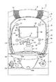
以下、本発明に係る遊技機の実施形態として、遊技場等に設置されるパチンコ機を図面に沿って説明する。図1は本発明の実施形態におけるパチンコ機の外部構造を示す正面図である。なお、本発明に係る遊技機の押しボタン部54を、回胴リール装置を有するスロットマシンにも同様に適用することが可能であり、その場合は、スロットマシンに備えたストップボタンやベットボタン等に適用される。
Hereinafter, as an embodiment of a gaming machine according to the present invention, a pachinko machine installed in a game hall or the like will be described with reference to the drawings. FIG. 1 is a front view showing an external structure of a pachinko machine according to an embodiment of the present invention. Note that the
パチンコ機1は、図1に示すように、発射ハンドル2の操作による発射装置(図示せず)の作動で遊技球(所謂パチンコ玉)を遊技盤3の遊技領域3aに向かって打ち出しつつ遊技を行うもので、所謂確率変動等の大当たりが発生した状態でアタッカー5に入球した遊技球に対応する数の遊技球を払い出すように構成されている。上記確率変動当たり(「確変当たり」とも言う)とは、抽選の結果、確変モードの大当たりが当選したとき、少なくとも当該確変モードによる遊技状態において次なる大当たりを引くまでの間、遊技者に有利な付加価値を付与し得る特殊状態を意味する。これに対し、当該特殊状態にならない大当たりとして「通常当たり」がある。
As shown in FIG. 1, the
本パチンコ機1は、開口を有する枠体状の筐体6と、遊技盤3を支持した形で筐体6に開閉可能に支持された前扉7とを有しており、前扉7の前面には、透明ガラス9を有するガラス枠10が開閉可能に取り付けられている。透明ガラス9の奥側には、遊技盤3が配設されている。前扉7における遊技盤3の左右には演出用照明装置11が配設されており、前扉7における上部左右、及び下部の皿ユニット16の左右には、スピーカ(図示せず)を有する放音装置12が夫々に配設されている。そして、前扉7の上部における両放音装置12,12の間には、演出用照明装置8が配設されている。なお、筐体6及び前扉7等により遊技機本体が構成されている。
The
また、ガラス枠10における中央部右方には、前扉7を筐体6側に施錠又は解放し、或いは、ガラス枠10を前扉7側に施錠又は解放するための施錠装置13が配設されている。なお、図1中の符号14は、不図示の発射装置によって打ち出された遊技球を遊技盤3側に案内するガイドレールを示している。本パチンコ機1には、遊技中に遊技領域3aにて入賞することなく落下してアウト口(図示せず)に進入した遊技球をパチンコ機背面側に導くアウト球通路(図示せず)が設けられている。
Further, a
そして、前扉7における下部中央には皿ユニット16が設けられており、皿ユニット16における右上部には、賞球及び貸球を含む遊技球が供給される球供給口17が設けられ、皿ユニット16における右上部壁面には、球貸ボタン19a及び返却ボタン19bが設けられている。皿ユニット16の中央部左方には、該皿ユニット16上の遊技球を球発射装置(図示せず)付近から皿ユニット下部の球排出口(図示せず)を通して下方に排出するための第1球抜きボタン20aが配設されており、皿ユニット16の中央部下方には、皿ユニット16上の遊技球を球供給口17付近から上記球排出口を通して下方に排出するための第2球抜きボタン20bが配設されている。
A
また、前扉7における皿ユニット16の右側下方には、上記球発射装置を操作して遊技球を遊技盤3に向けて打ち出すための発射ハンドル2が設けられている。更に、皿ユニット16の下部左方には、台座部15と灰皿21とが配設されており、該台座部15の中央部には、遊技参加ボタンとして機能する押しボタン装置50が配設されている。
A launch handle 2 for operating the ball launching device to launch the game ball toward the game board 3 is provided below the right side of the
遊技領域3aの中央部分には、ステージSを有するセンター飾り23が配設されている。センター飾り23の下部左右には、大当たり抽選に寄与しない一般の入賞が行われる入賞口25,26が配設されており、センター飾り23の下方には、始動チャッカー27と、アタッカー5とが順次配設されている。
A center ornament 23 having a stage S is disposed at the center of the
始動チャッカー27は、大当たり抽選実行の契機となり得る入賞が行われるものであり、開放位置と閉止位置とに開閉動作するように始動チャッカー開閉ソレノイド(図示せず)によって作動させられる。始動チャッカー27の直上方には、所謂命釘としての一対の障害釘30が打ち込まれている。
The
アタッカー5は、大当たり発生時に開放され、遊技盤3の遊技領域3aに打ち出されて転動落下する遊技球を入賞させるものであり、大当たり発生中、例えば、1回の開放で9個の入球を完了した時点で閉じ、当該開閉動作を15回(つまり、15ラウンド)繰り返すように構成される。なお、これらの入球数並びに開閉動作の回数は、9個や15回に限定されることはなく、必要に応じて適宜設定され得るものである。
The attacker 5 is released when a big hit occurs, and wins a game ball that is launched into the
遊技領域3aには、センター飾り23の四方に風車31が夫々配設されており、ステージSの下方における始動チャッカー27の左側には、スルーゲート32が配設されている。このスルーゲート32は、始動チャッカー27を開閉動作させるための普通図柄抽選の契機となる遊技球通過が行われる役物である。
In the
遊技領域3aにおけるスルーゲート32、入賞口25,26及び始動チャッカー27等の周囲には、センター飾り23のステージSから零れた遊技球や、発射されてからステージSに関与せずに落下してくる遊技球を適宜散らし、或いは入球に導くようにするための障害釘33を含む多数の障害釘が打ち込まれている。
A game ball spilled from the stage S of the center ornament 23 or a ball that has fallen without being involved in the stage S after being fired around the through
上記センター飾り23は、その中央部に、遊技盤3側に固定された画像表示装置35を露出する開口36を有し、左上部にワープ導入口37を有し、開口36の下側に上記ステージSを有し、該ステージSの下側に、ステージS上で転動して該ステージSの所定位置の落下孔(図示せず)に落下した遊技球を始動チャッカー27に向け放出する放出口49を有している。ワープ導入口37に対向するように、一対の障害釘39が打ち込まれている。ワープ導入口37の周囲や上方側にも、遊技球を適宜散らし、或いは入球に導くようにするための多数の障害釘(図示せず)が打ち込まれている。このような本パチンコ機1では、遊技領域3aに打ち出された遊技球Baを始動チャッカー27等に、ステージSを介して入球させ又はステージSを介さず直接入球させ得るように遊技が進められる。
The center decoration 23 has an
なお、上記「ワープ導入」という語句は、遊技領域3aに打ち出された遊技球を、当該遊技領域3aの比較的下側に位置する不図示の道釘等を経ることなく、始動チャッカー27の上に導くことを意味する概念である。また、上記「道釘」とは、遊技領域3aにおいて始動チャッカー27左右に打ち込まれた複数本の障害釘(図示せず)の列を意味するもので、上方から転動落下してきた遊技球を始動チャッカー27方向に導く役割を担っている。
Note that the phrase “introducing warp” means that the game ball launched into the
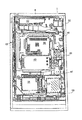
ついで、本パチンコ機1の背面構造について図2を参照して説明する。同図は、本パチンコ機1の背面構造を示す背面図である。
Next, the back structure of the
すなわち、図2に示すように、パチンコ機1の前扉背面における上部左方には、賞球タンク43が取り付けられており、この賞球タンク43の下方に、副制御基板38、主制御基板40、及び払出し制御基板51がこの順に配設されている。また、前扉背面における上部右方には、外部端子板52が取り付けられており、この外部端子板52の下方に、整列待機通路45、賞球装置46、賞球排出通路47、電源ユニット41、及び発射装置(図示せず)用の発射制御基板53がこの順に配設されている。パチンコ機1の前扉背面における左側部には、施錠装置13が配設されている。
That is, as shown in FIG. 2, a prize ball tank 43 is attached to the upper left side of the back of the front door of the
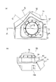
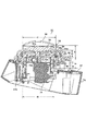
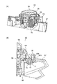
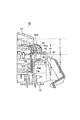
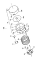
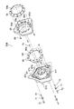
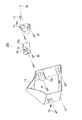
次に、本実施の形態における押しボタン装置50を図面に沿って説明する。なお、図3は押しボタン装置50の外観を示す図であり、同図(a)は押しボタン装置50を上方から見下ろした状態で示す平面図、同図(b)は押しボタン装置50を側方から見た状態で示す側面図である。図4は図3のC−C線で切断した状態で示す断面図である。図5(a)は図3のA−A線で切断した状態で示す断面図であり、図5(b)は振動防止ゴム等の配置を示す側面断面図である。図6は押しボタン部に対する押圧操作を検出するフォトセンサの部位周辺を示す図3のB−B線に沿った側面断面図である。図7は押しボタン装置50における第1の部位50Aを分解した状態で示す分解斜視図、図8は押しボタン装置50における第2の部位50Bを分解した状態で示す分解斜視図、図9は押しボタン装置50における第3の部位50Cを分解した状態で示す分解斜視図である。
Next, the
すなわち、図7に示すように、押しボタン装置50における第1の部位50Aは、ボタンベース部57と、該ボタンベース部57に装着される略円筒状のボタン操作カバー55、円板状の回転部材56、ボタン動作バネ(付勢手段)58、及びLED基板59とを有している。
That is, as shown in FIG. 7, the
ボタンベース部57は、全体的に略円筒状に形成されており、回転部材56の外径よりやや小さい内径を有する円形開口57aと、筒状の嵌込み部57hと、該嵌込み部57hの外周面に90゜間隔で突出形成された突起部57cと、嵌込み部57hの下方側に形成された被支持面57fと、該被支持面57fと嵌込み部57hとの間から外方に突出するように形成されて押しボタン部54の移動時の下限位置を規定する規定壁部57gと、被支持面57fにおける点対称の位置に2つ形成された鈎状で弾性を有する係止突起57bとを備えて構成される。
The
更に、被支持面57fにおける2つの係止突起57bの間には、振動モータ60を装着するための装着部57dが形成され、該装着部57dの両側には2つの係止鈎部57eが突出形成されており、振動モータ60が、装着部57dに位置した状態で左右の係止鈎部57eに振動モータホルダ61が係止された状態で固定される。なお、これらボタン操作カバー55、回転部材56及びボタンベース部57により押しボタン部54が構成されている。
Further, a mounting
回転部材56は、中心部から裏面側に突出するボス部56aを有している。ボタン操作カバー55は、円筒状の被支持面55bに90゜間隔で形成された係合穴部55aを有しており、被支持面55bを嵌込み部57hに被嵌して突起部57cに係合穴部55aを係合させた状態で、ボス部56aを円形開口57aに挿通した状態の回転部材56を内方に収容する。更に、ボタンベース部57の内周には、内方にLED基板59が嵌挿された状態のボタン動作バネ58が図7の下側から嵌挿される。該LED基板59は、中心部に円孔59aを有し、かつ該円孔59aを中心に複数のLED62が実装されており、タッピングビス63を介してボタンフレーム67の装着部67a(図8参照)に固定される。
The rotating
また、図8に示すように、押しボタン装置50における第2の部位50Bは、ボタンフレーム67と、該ボタンフレーム67に固定されるLED演出基板66、該LED演出基板66を覆う状態でボタンフレーム67に固定されるボタン外装カバー65と、該ボタン外装カバー65の中央部に装着される発光透明カバー64とを備えて構成されている。
Further, as shown in FIG. 8, the
ボタンフレーム67は、中央部に、上方に突出するように形成された円筒状の突出部67fを有しており、該突出部67fの内周部には、一段下がった状態で段差状に形成されて中心部に円孔67cを有する装着部67aが設けられている。ボタンフレーム67は、突出部67fの外周面との間に円形の空隙をあけた状態で形成された円筒状内壁面67bと、該円筒状内壁面67bの外方側に形成されたボス開口部67dと、裏面側に突出するボス部67eとを備えて構成される。
The
LED演出基板66は、中央開口66aを有する環状に構成されその外縁部に沿って複数のLED69が実装されており、ボス開口部67d等に対し位置決めした状態でボタンフレーム67側に装着されて、タッピングビス70により該ボタンフレーム67に固定される。
The
ボタン外装カバー65は、円筒状の中央開口65aを有し、かつ該中央開口65aの下部から段差部65dを介して続くように形成された、該中央開口65aより内径が小さい円筒状の支持面65eを有している。更に、ボタン外装カバー65は、中央開口65aを中心として複数形成された開口部65bを有しており、裏面側から貫通されるタッピングビス68を介して、中央部に円形開口及び該円形開口内周面である支持面64aを有する発光透明カバー64を固定した状態で、各開口部65bをLED演出基板66のLED69に対向させた状態でボタンフレーム67に装着される。
The
また、ボタンフレーム67のボス開口部67dには、その裏面側(図8の左側)から、中心部に振動防止カラー73が嵌挿された状態の振動防止ゴム71が嵌合されて、タッピングビス72を介して固定される。
Further, the
更に、押しボタン装置50における第3の部位50Cは、図9に示すように、本体ケース74と、ボタンフレーム67にタッピングビス80を介して固定される、フォトセンサ79を実装した操作スイッチ基板75と、ボタンフレーム67の円孔67cから回転軸76aを突出した状態で装着部67aの裏面にタッピングビス81を介して固定されるステッピングモータ76とを備えて構成される。上記フォトセンサ79は、発光素子と受光素子間の間隙79aに進退する被支持面57f(図6参照)が該発光素子と受光素子間を開放したり遮光したりすることで押しボタン部54に対する押圧操作を検出するフォトインタラプタを構成している。
Further, as shown in FIG. 9, the
また、円孔67cから突出する回転軸76aの先端部には、モータブッシュ77が、被嵌した状態でセットビス82によって固定される。本体ケース74には、外側から内側に膨出するように形成されたボス部74bが複数形成されており、これらボス部74bには、タッピングビス78を介してボタンフレーム67が固定される。
In addition, a
押しボタン装置50は、図3(a),(b)に示すように、下方から上方に向かって、本体ケース74、ボタンフレーム67、ボタン外装カバー65、発光透明カバー64、及びボタン操作カバー55が配設されている。台座部15に装着される押しボタン装置50は、ボタン操作カバー55を上方に突出させて斜め前方にやや傾斜した状態で配置される。
As shown in FIGS. 3A and 3B, the
更に、押しボタン装置50は、図4に示すように、ボタンフレーム67の突出部67fの外周面に対しやや隙間をあけた状態で被嵌したボタン動作バネ58により、ボタンベース部57、回転部材56及びボタン操作カバー55からなる押しボタン部54が上方に向けて付勢されており、係止突起57b(図7参照)がボタン外装カバー65の係止部(図示せず)に係止されることで、ボタンベース部57がボタンフレーム67側から外れないように支持される。
Further, as shown in FIG. 4, the
この状態で、押しボタン部54は、図4の上方に位置するボタン操作カバー55の被支持面55bが、発光透明カバー64の円形開口内周面である支持面64aにより摺動自在に案内支持され、かつ下方に位置するボタンベース部57の被支持面57fがボタン外装カバー65の支持面65eにより摺動自在に支持されて、図の上下方向(押圧方向)において極めて安定した状態で動作し得る。
In this state, the
また、押しボタン部54では、押圧方向にて互いに離間した二箇所に設けられた上記支持面64a,65eにより摺動支持部が構成されており、これら支持面64a,65eにより押しボタン部54が摺動自在に支持される。そして、支持面64aの長さd5は被支持面55bの長さd3より短く形成され、支持面65eの長さd6は被支持面57fの長さd4と同程度に形成されており、支持面64a,65eを合わせた長さ(d5+d6)が、二箇所の被支持面55b,57fを合わせた長さ(d3+d4)に比して短い寸法となるように設定される。
Moreover, in the
更に、支持面64a,65eからなる摺動支持部は、押しボタン部54の外周面をその全域に亘って取り囲むように形成されている。また、被支持面55bと支持面64aとの間の間隙のサイズ(直径)d1よりも、被支持面57fと支持面65eとの間の間隙のサイズ(直径)d2が小さくなるように構成されて、押しボタン部54の全体が大型化することが回避されている。
Furthermore, the sliding support part which consists of
また、図5(a)に示すように、ボタンベース部57の被支持面57fに設けられた装着部57dには、上記振動モータ60が装着されている。該振動モータ60は、ステッピングモータ76に比して極めて小型に構成されており、該振動モータ60の回転駆動により、その偏心した回転軸によって発生する振動が押しボタン部54の全体を振動させる。これにより、押しボタン部54を押圧操作した遊技者が当該振動を手に感じることで、大当たりの期待感を味わうことができる。
Further, as shown in FIG. 5A, the
ここで、上記振動モータ60の回転駆動により押しボタン部54だけを振動させ得るようにした振動防止構造について説明する。
Here, a vibration preventing structure in which only the
すなわち、図5(b)に示すように、ボタン外装カバー65からボタンフレーム67側に突出するように形成されたボス部65cは、ボタンフレーム67に形成されたボス開口部67dの内径に比して小径に形成され、ボス部65cの外周部とボス開口部67dの内周部との間には充分な空隙が設けられている。従って、中心部に振動防止カラー73が嵌挿された状態で該振動防止カラー73に貫通したタッピングビス72がボス部65cに螺合されることで、ボタンフレーム67とボタン外装カバー65との間に振動防止ゴム71が介在されることになり、振動モータ60の回転駆動による振動をボタンフレーム67側に伝えることなく、押しボタン部54だけを振動させることができる。
That is, as shown in FIG. 5B, the
次に、本パチンコ機1による作用について説明する。すなわち、本パチンコ機1に対面して着座した遊技者が発射ハンドル2を握り、適宜の角度に回動操作すると、発射装置の作動で遊技球が所定の時間間隔で遊技領域3aに向けて連続的に発射される。すると、遊技領域3aに打ち出されて転動落下する多数の遊技球は、始動チャッカー27や入賞口25,26に適時入賞し、或いは、これらに関与せずに転動落下して、遊技領域3a最下部のアウト口(図示せず)から遊技盤3背面側に排出される。
Next, the operation of the
遊技領域3aに打ち出された遊技球の一部がワープ導入口37に入球すると、その遊技球はステージS上に放出された後、該ステージSの傾斜に沿って転動し、或るものはそのまま遊技領域3aに落下し、或るものは放出口49から始動チャッカー27に向けて放出され、高い入賞確率(略100%)で該チャッカー27に入賞する。
When a part of the game ball launched into the
ところで、始動チャッカー27に入賞した場合、その時点での保留球数が所定数未満であれば、乱数カウンタを用いた大当たり抽選が行われるが、該抽選で当選した場合、更に、大当たりの種別に対応する変動パターンが決定される。これにより、画像表示装置35に表示される当たり図柄がセットされる。一方、大当たり抽選で外れた場合には、変動の結果、外れに対応する図柄が最終的に揃う旨の変動パターンが決定され、画像表示装置35に表示される外れ図柄がセットされる。
By the way, when winning the starting
そして、画像表示装置35に表示すべき演出内容に関する信号に基づき、該画像表示装置35が駆動され、大当たり抽選結果に関する内容等が演出表示される。画像表示装置35の画面上に表れた抽選結果が大当たり決定である場合、アタッカー5が開放され、所定数入賞が終了する(又は所定時間が経過する)毎に閉塞する動作を所定ラウンド数だけ繰り返される。これにより、アタッカー5に入賞した遊技球に対応する多量の遊技球が、球供給口17から皿ユニット16に払い出されることとなる。
The
上述した遊技中、画像表示装置35の画面に、遊技者を遊技に参加させるための「今だボタンを叩け!」等のメッセージが表示された場合に、遊技者が押しボタン部54のボタン操作カバー55を叩く(押圧操作する)と、図4において、被支持面55bが発光透明カバー64の支持面64aにより摺動自在に案内支持され、かつ下方の被支持面57fがボタン外装カバー65の支持面65eにより摺動自在に案内支持される。これにより、押しボタン部54は、上下方向において或る距離だけ(該距離が大きいほど、安定支持効果が高くなる)離間した状態で配設された支持面64a,65eによって荷重を分散され、壁面同士の摩擦抵抗を低減しつつ安定に支持される。
During the above-described game, when a message such as “Tap the button now!” For causing the player to participate in the game is displayed on the screen of the
つまり、押しボタン装置50では、押しボタン部54をその押圧方向にて摺動自在に支持する摺動支持部が、該押圧方向にて互いに離間した二箇所に設けられた支持面64a,65eにより押しボタン部54を摺動自在に案内支持するように構成されるので、互いに離れた二箇所の支持面64a,65eにて押しボタン部54を面接触支持することで、押しボタン部54の外周面全体を摺動支持する場合に比して摩擦抵抗を大幅に低減しながら、安定に支持して耐久性を高めることができる。また、たとえ斜め押しされたとしても、傾いた押しボタン部54を、押圧方向で離れた位置の2つの支持面64a,65eにより安定して案内支持できるので、押しボタン部54が食い込んで復帰不良を生じるような不具合の発生を可及的に減少させることができる。
That is, in the
また、押しボタン部54が、二箇所の支持面64a,65eにてそれぞれ摺動支持される二箇所の被支持面55b,57fを有し、該支持面64a,65eを合わせた長さが、被支持面55b,57fを合わせた長さより短く設定されているので、比較的短い二箇所の支持面64a,65eによって押しボタン部54の二箇所の被支持面55b,57fをそれぞれ安定に摺動支持できることにより、面接触しながらも接触摩擦抵抗を大幅に低減して押しボタン部54の復帰不良の減少効果を一層高めることができる。上記押しボタン部54に対する押圧操作は、該押圧操作で上下方向に進退動作する被支持面57fの下部がフォトセンサ79(図6参照)で検出され、該検出信号が制御部(図示せず)に送られることに基づいて認識される。更に、本押しボタン装置50では、上記摺動支持部が、押しボタン部54の外周面をその全域に亘って取り囲むように形成されるので、押しボタン部54がより安定した状態で摺動自在に支持される。
The
例えば、遊技中に画像表示装置35の画面に表示された上記メッセージが、回転部材56を点灯させつつ回転させる所謂一発告知である場合に、指示に従って遊技者がボタン操作カバー55をボタン動作バネ58の付勢力に抗して叩くと(押し込むと)、該操作が上記フォトセンサ79で検出され、該検出信号を受けた制御部の制御により、ステッピングモータ76が所定回転数だけ回転させられる。これにより、透明なボタン操作カバー55側から視認している遊技者は、該ボタン操作カバー55の内方で急激に回転する回転部材56を見ることで、大当たりの期待度が極めて高いことを突然知ることで喜悦感を味わうことになる。これは、回転部材56の回転時の発光色の違い(発光色が「赤」など暖色系の方がチャンスが大きい)、或いは、回転時間の違い(回転時間が長い方がチャンスが大きい)によって、大当たり発生の期待度が異なるように設定される。
For example, when the message displayed on the screen of the
また、画面に表示された上記メッセージが、押しボタン部54の振動でチャンスの大きさを示す予告である場合に、遊技者がボタン操作カバー55をボタン動作バネ58に抗して叩くと(押し込むと)、該操作がフォトセンサ79により検出され、該検出信号を受けた上記制御部の制御により、振動モータ60が回転駆動されて押しボタン部54が振動し、振動するボタン操作カバー55から遊技者の手に振動が伝えられる。これにより、押しボタン部54を押した遊技者は、急激に振動する押しボタン部54から振動を受けることで、大当たりに発展するチャンスが大きいことを知り、喜悦感を味わうことになる。これは、振動の大きさ、長さによって、大当たり発生までの期待度が異なるように設定される。
Further, when the message displayed on the screen is a warning indicating the magnitude of the chance by the vibration of the
なお、本実施の形態では、押しボタン部54、及び該押しボタン部54を案内支持する支持面64a,65eも円筒形状に構成されたが、この形状に限らず、三角形状、四角形状等の多角形状、或いはこれら以外の不規則な形状に構成されても良いことは勿論である。
In this embodiment, the
以上、本発明をその好適な実施の形態に基づいて説明したが、本発明の遊技機は、上記実施形態の構成にのみ限定されるものではなく、上記実施形態の構成から種々の修正及び変更を施した遊技機も、本発明の範囲に含まれる。 As mentioned above, although this invention was demonstrated based on the suitable embodiment, the game machine of this invention is not limited only to the structure of the said embodiment, A various correction and change from the structure of the said embodiment. The gaming machine which has been subjected to is also included in the scope of the present invention.
1 遊技機(パチンコ機)
50 押しボタン装置
54 押しボタン部
55b,57f 被支持面
58 付勢手段(ボタン動作バネ)
64a,65e 摺動支持部(支持面)
d3,d4 被支持面の長さ
d5,d6 支持面の長さ
1 Pachislot machines (pachinko machines)
50 Push-
64a, 65e Sliding support part (support surface)
d 3 , d 4 supported surface length d 5 , d 6 supported surface length
Claims (3)
前記押しボタン装置は、押圧操作される押しボタン部と、該押しボタン部をその押圧方向にて摺動自在に支持する摺動支持部と、前記押しボタン部を前記押圧方向と逆の方向に付勢する付勢手段と、を有し、
前記摺動支持部は、前記押圧方向にて互いに離間した二箇所に設けられた支持面を有し、かつ該二箇所の支持面により前記押しボタン部を摺動自在に案内支持してなる、
ことを特徴とする遊技機。 In a gaming machine comprising a push button device that is pressed according to the game,
The push button device includes a push button portion to be pressed, a sliding support portion that slidably supports the push button portion in the pressing direction, and the push button portion in a direction opposite to the pressing direction. A biasing means for biasing,
The sliding support portion has support surfaces provided at two locations spaced apart from each other in the pressing direction, and the push button portion is slidably guided and supported by the two support surfaces.
A gaming machine characterized by that.
前記二箇所の支持面を合わせた長さは、前記二箇所の被支持面を合わせた長さに比して短い寸法に設定されてなる、
請求項1記載の遊技機。 The push button part has two supported surfaces that are slidably supported by the two supporting surfaces, and
The combined length of the two supporting surfaces is set to a shorter dimension than the combined length of the two supported surfaces.
The gaming machine according to claim 1.
請求項1又は2記載の遊技機。 The sliding support part is formed so as to surround the entire outer peripheral surface of the push button part.
The gaming machine according to claim 1 or 2.
Priority Applications (1)
| Application Number | Priority Date | Filing Date | Title |
|---|---|---|---|
| JP2008320021A JP5305512B2 (en) | 2008-12-16 | 2008-12-16 | Game machine |
Applications Claiming Priority (1)
| Application Number | Priority Date | Filing Date | Title |
|---|---|---|---|
| JP2008320021A JP5305512B2 (en) | 2008-12-16 | 2008-12-16 | Game machine |
Publications (2)
| Publication Number | Publication Date |
|---|---|
| JP2010142291A true JP2010142291A (en) | 2010-07-01 |
| JP5305512B2 JP5305512B2 (en) | 2013-10-02 |
Family
ID=42563353
Family Applications (1)
| Application Number | Title | Priority Date | Filing Date |
|---|---|---|---|
| JP2008320021A Expired - Fee Related JP5305512B2 (en) | 2008-12-16 | 2008-12-16 | Game machine |
Country Status (1)
| Country | Link |
|---|---|
| JP (1) | JP5305512B2 (en) |
Cited By (23)
| Publication number | Priority date | Publication date | Assignee | Title |
|---|---|---|---|---|
| DE102011076983A1 (en) | 2010-06-23 | 2012-10-04 | Mori Seiki Co., Ltd. | Displacement detecting device |
| JP2013022159A (en) * | 2011-07-19 | 2013-02-04 | Kyoraku Sangyo Kk | Game machine |
| JP2013169251A (en) * | 2012-02-17 | 2013-09-02 | Newgin Co Ltd | Game machine |
| JP2013183904A (en) * | 2012-03-08 | 2013-09-19 | Heiwa Corp | Game machine |
| JP2015192792A (en) * | 2014-03-31 | 2015-11-05 | 株式会社三共 | Game machine |
| JP2015202287A (en) * | 2014-04-15 | 2015-11-16 | 株式会社ニューギン | Game machine |
| JP2015202286A (en) * | 2014-04-15 | 2015-11-16 | 株式会社ニューギン | Game machine |
| JP2016032653A (en) * | 2015-09-29 | 2016-03-10 | 株式会社ニューギン | Game machine |
| JP2016087250A (en) * | 2014-11-07 | 2016-05-23 | 株式会社平和 | Game machine |
| JP2016097040A (en) * | 2014-11-21 | 2016-05-30 | 株式会社三共 | Game device |
| JP2016101529A (en) * | 2016-02-12 | 2016-06-02 | 株式会社藤商事 | Game machine |
| JP2016106864A (en) * | 2014-12-08 | 2016-06-20 | 株式会社サンセイアールアンドディ | Game machine |
| JP2017064267A (en) * | 2015-10-01 | 2017-04-06 | 株式会社サンセイアールアンドディ | Game machine |
| JP2017099661A (en) * | 2015-12-02 | 2017-06-08 | 株式会社三共 | Game device |
| JP2017136454A (en) * | 2017-05-17 | 2017-08-10 | 京楽産業.株式会社 | Game machine |
| JP2017136456A (en) * | 2017-05-17 | 2017-08-10 | 京楽産業.株式会社 | Game machine |
| JP2017189668A (en) * | 2017-07-27 | 2017-10-19 | 株式会社ユニバーサルエンターテインメント | Game machine |
| JP2017192660A (en) * | 2016-04-22 | 2017-10-26 | 株式会社三共 | Slot machine |
| JP2017192661A (en) * | 2016-04-22 | 2017-10-26 | 株式会社三共 | Slot machine |
| JP2018149153A (en) * | 2017-03-14 | 2018-09-27 | 株式会社ニューギン | Game machine |
| JP2018149154A (en) * | 2017-03-14 | 2018-09-27 | 株式会社ニューギン | Game machine |
| JP2018149156A (en) * | 2017-03-14 | 2018-09-27 | 株式会社ニューギン | Game machine |
| JP2018149155A (en) * | 2017-03-14 | 2018-09-27 | 株式会社ニューギン | Game machine |
Families Citing this family (4)
| Publication number | Priority date | Publication date | Assignee | Title |
|---|---|---|---|---|
| JP6215759B2 (en) * | 2014-04-15 | 2017-10-18 | 株式会社ニューギン | Game machine |
| JP6215760B2 (en) * | 2014-04-15 | 2017-10-18 | 株式会社ニューギン | Game machine |
| JP6180988B2 (en) * | 2014-04-15 | 2017-08-16 | 株式会社ニューギン | Game machine |
| JP6215761B2 (en) * | 2014-04-15 | 2017-10-18 | 株式会社ニューギン | Game machine |
Citations (3)
| Publication number | Priority date | Publication date | Assignee | Title |
|---|---|---|---|---|
| JPS6075929U (en) * | 1983-10-31 | 1985-05-28 | 株式会社ジエルコ | push button switch |
| JP2006107962A (en) * | 2004-10-06 | 2006-04-20 | Samii Kk | Switch device for game machine |
| JP2007167474A (en) * | 2005-11-25 | 2007-07-05 | Aruze Corp | Button unit for gaming machines |
-
2008
- 2008-12-16 JP JP2008320021A patent/JP5305512B2/en not_active Expired - Fee Related
Patent Citations (3)
| Publication number | Priority date | Publication date | Assignee | Title |
|---|---|---|---|---|
| JPS6075929U (en) * | 1983-10-31 | 1985-05-28 | 株式会社ジエルコ | push button switch |
| JP2006107962A (en) * | 2004-10-06 | 2006-04-20 | Samii Kk | Switch device for game machine |
| JP2007167474A (en) * | 2005-11-25 | 2007-07-05 | Aruze Corp | Button unit for gaming machines |
Cited By (23)
| Publication number | Priority date | Publication date | Assignee | Title |
|---|---|---|---|---|
| DE102011076983A1 (en) | 2010-06-23 | 2012-10-04 | Mori Seiki Co., Ltd. | Displacement detecting device |
| JP2013022159A (en) * | 2011-07-19 | 2013-02-04 | Kyoraku Sangyo Kk | Game machine |
| JP2013169251A (en) * | 2012-02-17 | 2013-09-02 | Newgin Co Ltd | Game machine |
| JP2013183904A (en) * | 2012-03-08 | 2013-09-19 | Heiwa Corp | Game machine |
| JP2015192792A (en) * | 2014-03-31 | 2015-11-05 | 株式会社三共 | Game machine |
| JP2015202286A (en) * | 2014-04-15 | 2015-11-16 | 株式会社ニューギン | Game machine |
| JP2015202287A (en) * | 2014-04-15 | 2015-11-16 | 株式会社ニューギン | Game machine |
| JP2016087250A (en) * | 2014-11-07 | 2016-05-23 | 株式会社平和 | Game machine |
| JP2016097040A (en) * | 2014-11-21 | 2016-05-30 | 株式会社三共 | Game device |
| JP2016106864A (en) * | 2014-12-08 | 2016-06-20 | 株式会社サンセイアールアンドディ | Game machine |
| JP2016032653A (en) * | 2015-09-29 | 2016-03-10 | 株式会社ニューギン | Game machine |
| JP2017064267A (en) * | 2015-10-01 | 2017-04-06 | 株式会社サンセイアールアンドディ | Game machine |
| JP2017099661A (en) * | 2015-12-02 | 2017-06-08 | 株式会社三共 | Game device |
| JP2016101529A (en) * | 2016-02-12 | 2016-06-02 | 株式会社藤商事 | Game machine |
| JP2017192660A (en) * | 2016-04-22 | 2017-10-26 | 株式会社三共 | Slot machine |
| JP2017192661A (en) * | 2016-04-22 | 2017-10-26 | 株式会社三共 | Slot machine |
| JP2018149153A (en) * | 2017-03-14 | 2018-09-27 | 株式会社ニューギン | Game machine |
| JP2018149154A (en) * | 2017-03-14 | 2018-09-27 | 株式会社ニューギン | Game machine |
| JP2018149156A (en) * | 2017-03-14 | 2018-09-27 | 株式会社ニューギン | Game machine |
| JP2018149155A (en) * | 2017-03-14 | 2018-09-27 | 株式会社ニューギン | Game machine |
| JP2017136454A (en) * | 2017-05-17 | 2017-08-10 | 京楽産業.株式会社 | Game machine |
| JP2017136456A (en) * | 2017-05-17 | 2017-08-10 | 京楽産業.株式会社 | Game machine |
| JP2017189668A (en) * | 2017-07-27 | 2017-10-19 | 株式会社ユニバーサルエンターテインメント | Game machine |
Also Published As
| Publication number | Publication date |
|---|---|
| JP5305512B2 (en) | 2013-10-02 |
Similar Documents
| Publication | Publication Date | Title |
|---|---|---|
| JP5305512B2 (en) | Game machine | |
| JP2010099334A (en) | Game machine | |
| JP2005052322A (en) | Game machine | |
| JP4954697B2 (en) | Game machine | |
| JP2005245609A (en) | Game machine | |
| JP5094287B2 (en) | Slot machine | |
| JP2007105278A (en) | Game machine | |
| JP2005328899A5 (en) | ||
| JP2005245605A (en) | Game machine | |
| JP2024152056A (en) | Game machine | |
| JP2008012100A (en) | Game machine and shooting handle device | |
| JP5229808B2 (en) | Game machine | |
| JP2009153707A (en) | Game machine | |
| JP4214136B2 (en) | Game machine | |
| JP2005245477A (en) | Game machine | |
| JP6050964B2 (en) | Game machine | |
| JP5486843B2 (en) | Game machine | |
| JP2006000510A (en) | Spin drum type game machine | |
| JP2006014842A (en) | Rotary-body-type game machine | |
| JP2007244499A (en) | Game machine | |
| JP2008126004A (en) | Game machine, and spacer holder for the same | |
| JP4895257B2 (en) | Hopper device for gaming machine | |
| JP2008079944A (en) | Game machine | |
| JP6501929B2 (en) | Gaming machine | |
| JP2024152054A (en) | Gaming Machines |
Legal Events
| Date | Code | Title | Description |
|---|---|---|---|
| A621 | Written request for application examination |
Free format text: JAPANESE INTERMEDIATE CODE: A621 Effective date: 20111004 |
|
| A977 | Report on retrieval |
Free format text: JAPANESE INTERMEDIATE CODE: A971007 Effective date: 20130110 |
|
| A131 | Notification of reasons for refusal |
Free format text: JAPANESE INTERMEDIATE CODE: A131 Effective date: 20130115 |
|
| A521 | Request for written amendment filed |
Free format text: JAPANESE INTERMEDIATE CODE: A523 Effective date: 20130228 |
|
| A131 | Notification of reasons for refusal |
Free format text: JAPANESE INTERMEDIATE CODE: A131 Effective date: 20130326 |
|
| A521 | Request for written amendment filed |
Free format text: JAPANESE INTERMEDIATE CODE: A523 Effective date: 20130523 |
|
| TRDD | Decision of grant or rejection written | ||
| A01 | Written decision to grant a patent or to grant a registration (utility model) |
Free format text: JAPANESE INTERMEDIATE CODE: A01 Effective date: 20130611 |
|
| A61 | First payment of annual fees (during grant procedure) |
Free format text: JAPANESE INTERMEDIATE CODE: A61 Effective date: 20130624 |
|
| R150 | Certificate of patent or registration of utility model |
Free format text: JAPANESE INTERMEDIATE CODE: R150 Ref document number: 5305512 Country of ref document: JP Free format text: JAPANESE INTERMEDIATE CODE: R150 |
|
| R250 | Receipt of annual fees |
Free format text: JAPANESE INTERMEDIATE CODE: R250 |
|
| R250 | Receipt of annual fees |
Free format text: JAPANESE INTERMEDIATE CODE: R250 |
|
| R250 | Receipt of annual fees |
Free format text: JAPANESE INTERMEDIATE CODE: R250 |
|
| S531 | Written request for registration of change of domicile |
Free format text: JAPANESE INTERMEDIATE CODE: R313531 |
|
| R350 | Written notification of registration of transfer |
Free format text: JAPANESE INTERMEDIATE CODE: R350 |
|
| R250 | Receipt of annual fees |
Free format text: JAPANESE INTERMEDIATE CODE: R250 |
|
| R250 | Receipt of annual fees |
Free format text: JAPANESE INTERMEDIATE CODE: R250 |
|
| LAPS | Cancellation because of no payment of annual fees |