JP2010142220A - Fish line fastener of fishing reel and the assembly thereof - Google Patents
Fish line fastener of fishing reel and the assembly thereof Download PDFInfo
- Publication number
- JP2010142220A JP2010142220A JP2009024437A JP2009024437A JP2010142220A JP 2010142220 A JP2010142220 A JP 2010142220A JP 2009024437 A JP2009024437 A JP 2009024437A JP 2009024437 A JP2009024437 A JP 2009024437A JP 2010142220 A JP2010142220 A JP 2010142220A
- Authority
- JP
- Japan
- Prior art keywords
- reel
- fishing
- fishing line
- shaft portion
- thread stopper
- Prior art date
- Legal status (The legal status is an assumption and is not a legal conclusion. Google has not performed a legal analysis and makes no representation as to the accuracy of the status listed.)
- Pending
Links
Images

Classifications
-
- A—HUMAN NECESSITIES
- A01—AGRICULTURE; FORESTRY; ANIMAL HUSBANDRY; HUNTING; TRAPPING; FISHING
- A01K—ANIMAL HUSBANDRY; AVICULTURE; APICULTURE; PISCICULTURE; FISHING; REARING OR BREEDING ANIMALS, NOT OTHERWISE PROVIDED FOR; NEW BREEDS OF ANIMALS
- A01K89/00—Reels
- A01K89/01—Reels with pick-up, i.e. with the guiding member rotating and the spool not rotating during normal retrieval of the line
- A01K89/0111—Spool details
-
- A—HUMAN NECESSITIES
- A01—AGRICULTURE; FORESTRY; ANIMAL HUSBANDRY; HUNTING; TRAPPING; FISHING
- A01K—ANIMAL HUSBANDRY; AVICULTURE; APICULTURE; PISCICULTURE; FISHING; REARING OR BREEDING ANIMALS, NOT OTHERWISE PROVIDED FOR; NEW BREEDS OF ANIMALS
- A01K89/00—Reels
- A01K89/01—Reels with pick-up, i.e. with the guiding member rotating and the spool not rotating during normal retrieval of the line
Landscapes
- Life Sciences & Earth Sciences (AREA)
- Environmental Sciences (AREA)
- Animal Husbandry (AREA)
- Biodiversity & Conservation Biology (AREA)
Abstract
【課題】釣り用リールの糸止めにおいて、糸止めがばね部材により付勢されても釣り糸が切断及び損傷されにくくする
【解決手段】糸止め20は、釣り糸を釣り用リールに固定するために備えられている。リンクリップ20は、軸部21と、頭部22とを有する。頭部22は、軸部21に装着され、軸部21は釣り用リールに接続されている。糸止め20は、軸部21に対向する、頭部22の面22bに形成された環状溝22aを備える。環状溝22aは、軸部21と同心円状に配置されている。糸止め20は、コイルばね24と、ばね保持部25とを軸部21に装着することにより釣り用リールに接続されている。コイルばね24とばね保持部25は、軸部21に装着されたスナップリング23によって所定の位置に保持される。
【選択図】図5The fishing line is secured to a fishing reel by securing the fishing line to the fishing reel. It has been. The link clip 20 includes a shaft portion 21 and a head portion 22. The head portion 22 is attached to the shaft portion 21, and the shaft portion 21 is connected to a fishing reel. The thread stopper 20 includes an annular groove 22 a that is formed on the surface 22 b of the head portion 22 and faces the shaft portion 21. The annular groove 22 a is disposed concentrically with the shaft portion 21. The thread stopper 20 is connected to the fishing reel by attaching a coil spring 24 and a spring holding portion 25 to the shaft portion 21. The coil spring 24 and the spring holding portion 25 are held at predetermined positions by a snap ring 23 attached to the shaft portion 21.
[Selection] Figure 5
Description
本発明は、糸止め、特に、釣り用リールに釣り糸を止めるための糸止め及び糸止め組立体に関する。 The present invention relates to a thread clamp, and more particularly to a thread clamp and a thread clamp assembly for securing a fishing line to a fishing reel.
一般に、スピニングリール等の釣り用リールは、リール本体と、ハンドルと、ロータと、スプールと、スプールに装着された糸止めとを有する。リール本体は釣り竿に取り付けられる。ハンドルは、リール本体に回転自在に装着される。ロータは、リール本体に回転自在に装着される。スプールは、ロータの前部においてリール本体に装着され、前後移動自在である。釣り糸は、ロータによってガイドされ、スプールの外周面に巻き付けられる。 In general, a fishing reel such as a spinning reel includes a reel body, a handle, a rotor, a spool, and a thread stopper attached to the spool. The reel body is attached to a fishing rod. The handle is rotatably mounted on the reel body. The rotor is rotatably mounted on the reel body. The spool is mounted on the reel body at the front portion of the rotor and is movable back and forth. The fishing line is guided by the rotor and wound around the outer peripheral surface of the spool.
釣り糸を使用しない場合、通常、釣り糸の端部は、釣り糸がスプールから開放されないように糸止めに固定される。 When the fishing line is not used, the end portion of the fishing line is usually fixed to the thread stopper so that the fishing line is not released from the spool.
釣り糸を使用する場合、糸止めは、例えば、魚に撒き餌を与えるために「スポッド」または「スポッドロケット」等の撒き餌カゴをキャスティング毎に確実に略同一領域に着水させる。しかし、実際には、従来の糸止めは、その使用方法に関わらず、時間経過に伴って釣り糸の破損や切断を発生させることが知られている。 When using a fishing line, for example, the thread stopper ensures that a sowing bait such as a “spod” or “spod rocket” is landed in substantially the same region for each casting in order to feed the fish. However, in practice, it is known that the conventional thread stoppers cause breakage or cutting of the fishing line over time, regardless of how it is used.
例えば、従来の糸止めは面に沿って釣り糸を付勢することが知られている(例えば、特許文献1参照)。これにより、強力な保持力が加えられない限り、釣り糸は係止されない。しかし、保持力が強くなれば、釣り糸を糸止めの頭部の下で付勢しなければならないので、特にナイロン製の釣り糸を係止することはさらに困難になる。結果として、釣り糸がひどく損傷を受ける。 For example, it is known that a conventional thread stopper urges a fishing line along a surface (see, for example, Patent Document 1). As a result, the fishing line is not locked unless a strong holding force is applied. However, if the holding force is increased, the fishing line has to be urged under the head of the hook, so that it is more difficult to lock the fishing line made of nylon in particular. As a result, the fishing line is severely damaged.
上記問題を克服するために、受け面に段差部が備え、これにより釣り糸が容易に滑り落ちないようになっているものが知られている(例えば、特許文献2参照)。 In order to overcome the above problem, there is known a step provided on the receiving surface so that the fishing line does not easily slip off (for example, see Patent Document 2).
しかし、段差部の鋭い縁部が、釣り糸をひどく損傷または切断する場合がある。例えば、釣り用リールの表面に対して糸止めの頭部を保持するために、糸止めを付勢する保持ばねが使用されている。 However, the sharp edge of the step may severely damage or cut the fishing line. For example, in order to hold the head of the thread stopper against the surface of the fishing reel, a holding spring that biases the thread stopper is used.
釣り糸は、糸止めの頭部と、釣り用リール表面の段差部との間に保持される。時間経過に伴って、釣り糸は、クリップの頭部と、段差部の鋭い縁部との間に釣り糸を保持するための保持ばねからの力によって磨耗する。この結果、釣り糸の損傷または切断が発生する。 The fishing line is held between the head of the thread stopper and the stepped portion on the surface of the fishing reel. As time passes, the fishing line is worn by the force from the holding spring for holding the fishing line between the head of the clip and the sharp edge of the step. As a result, the fishing line is damaged or cut.
以上を鑑みると、この開示により、釣り用リール用の改良された糸止めの必要性は、当業者にとって明白である。また、この開示により、本発明が上記技術分野における当該必要性及び他の必要性を主張するものであることは、当業者にとって明白である。 In view of the foregoing, with this disclosure, the need for an improved thread clamp for fishing reels is apparent to those skilled in the art. Also, it will be apparent to those skilled in the art from this disclosure that the present invention claims this and other needs in the art.
本発明の各態様は、従来技術で発生している上記問題を解決する目的で創出されたものであり、本発明の課題は、釣り用リールの糸止めにおいて、糸止めがばね部材により付勢されても釣り糸が切断及び損傷されにくくすることにある。 Each aspect of the present invention has been created for the purpose of solving the above-mentioned problems occurring in the prior art, and the problem of the present invention is that the thread stopper is biased by a spring member in the thread stopper of a fishing reel. This is to prevent the fishing line from being cut and damaged.
本発明の一態様によれば、釣り用リール用糸止めが、釣り用リールに釣り糸を止めるために備えられる。糸止めは、軸部と、頭部とを有する。軸部は、釣り用リールに装着される。頭部は、軸部に設けられ、軸部よりも大きい外径を有する。また、頭部は環状溝を有し、環状溝は頭部の軸部に対向する面に形成されている。 According to one aspect of the present invention, a fishing reel thread clamp is provided for securing the fishing line to the fishing reel. The thread stopper has a shaft portion and a head portion. The shaft is mounted on a fishing reel. The head is provided on the shaft and has a larger outer diameter than the shaft. The head portion has an annular groove, and the annular groove is formed on a surface facing the shaft portion of the head portion.
この糸止めでは、釣り用リールに軸部が装着されると、頭部と釣り用リールとの間に釣り糸が保持される。このとき、頭部の軸部と対向する面に形成された環状溝に釣り糸が配置される。このため、例えば、釣り糸を糸止めから外すとき及びキャスティング時に釣り糸の糸止めに止められた途中に張力が作用するとき、糸止めが釣り用リールの表面から離反する方向に移動する。したがって、釣り糸が損傷及び切断されにくくなり、頭部と、釣り用リールの表面との間に釣り糸が確実に保持される。 In this thread stopper, when the shaft portion is attached to the fishing reel, the fishing line is held between the head and the fishing reel. At this time, the fishing line is arranged in an annular groove formed on a surface facing the shaft portion of the head. For this reason, for example, when the fishing line is removed from the hook and when tension is applied in the middle of being caught by the hook of the fishing line during casting, the hook stops moving away from the surface of the fishing reel. Therefore, the fishing line is not easily damaged or cut, and the fishing line is reliably held between the head and the surface of the fishing reel.
本発明の他の態様によれば、環状溝は軸部と同心円状に配置される。この場合には、頭部が軸部と同芯に配置されているので、環状溝を軸部と同芯に配置できる。 According to another aspect of the present invention, the annular groove is disposed concentrically with the shaft portion. In this case, since the head portion is disposed concentrically with the shaft portion, the annular groove can be disposed concentrically with the shaft portion.
本発明のさらに他の態様によれば、釣り用リールは、スプールに円筒形スカート部を備えたスピニングリールであり、頭部は、スカート部との間で釣り糸を保持する。この場合には、スピニングリールのスプールのスカート部と頭部との間に、損傷及び切断されることなく釣り糸が保持される。 According to still another aspect of the present invention, the fishing reel is a spinning reel having a cylindrical skirt portion on the spool, and the head portion holds the fishing line with the skirt portion. In this case, the fishing line is held between the skirt portion and the head portion of the spinning reel spool without being damaged or cut.
本発明のさらに他の態様によれば、スカート部は、外周面に形成された底が平坦で浅い凹部と、凹部に形成された貫通孔とを有し、軸部は、貫通孔に装着される。この場合には、頭部、環状溝及び凹部との間に、損傷及び切断されることなく釣り糸が保持される。ここでは、凹部で糸止めに係止された釣り糸が損傷しにくくなる。また、凹部を頭部の厚み分だけ凹ますことにより、頭部がスカートの外周面から突出しなくなる。 According to still another aspect of the present invention, the skirt portion has a recess having a flat bottom formed on the outer peripheral surface and a shallow recess, and a through hole formed in the recess, and the shaft portion is attached to the through hole. The In this case, the fishing line is held between the head, the annular groove and the recess without being damaged or cut. Here, the fishing line locked to the thread stopper by the recess is less likely to be damaged. Further, by denting the recess by the thickness of the head, the head does not protrude from the outer peripheral surface of the skirt.
本発明のさらに他の態様によれば、糸止め組立体は、スピニングリールのスプールに釣り糸を止めるための組立体であって、上記の糸止めと、ばね受け部材と、ばね部材と、を備えている。ばね受け部材は、スカート部の内周面より内周側で軸部に抜け止めされた部材である。ばね部材は、ばね受け部材とスカート部の内周部の貫通孔の周囲との間で配置され、糸止めをスプール中心に向かって付勢する。 According to still another aspect of the present invention, a thread stopper assembly is an assembly for stopping a fishing line on a spinning reel spool, and includes the above-described thread stopper, a spring receiving member, and a spring member. ing. The spring receiving member is a member that is secured to the shaft portion on the inner peripheral side from the inner peripheral surface of the skirt portion. The spring member is disposed between the spring receiving member and the periphery of the through hole in the inner peripheral portion of the skirt portion, and biases the thread stopper toward the center of the spool.
この糸止め組立体では、糸止めの軸部が貫通孔に配置され、頭部が凹部に配置される。そして、糸止めはばね部材によりスカート部の内周側に付勢される。この状態で釣り糸を凹部と頭部の間に挟むと、糸止めは、凹部からいったん離れて釣り糸が環状溝に配置されると、ばね部材により付勢されて凹部に向けて移動する。このとき、釣り糸が凹部と環状溝との間で保持されるので、糸止めがばね部材により付勢されても釣り糸が切断及び損傷されにくくすることになる。 In this thread clamp assembly, the thread clamp shaft is disposed in the through hole and the head is disposed in the recess. The thread stopper is biased toward the inner peripheral side of the skirt portion by the spring member. When the fishing line is sandwiched between the recess and the head in this state, the fishing line is urged by the spring member to move toward the recess once the fishing line is disposed in the annular groove once separated from the recess. At this time, since the fishing line is held between the recess and the annular groove, the fishing line is less likely to be cut and damaged even if the thread stopper is biased by the spring member.
釣り糸は、釣り用リールの表面の糸止めに装着されると、損傷及び切断されることなく、頭部と、釣り用リールの表面との間に確実に保持される。 The fishing line is securely held between the head and the surface of the fishing reel without being damaged or cut when the fishing line is attached to the thread stopper on the surface of the fishing reel.
以下、本発明の一実施形態について、図面参照して説明する。この開示により、本発明の一実施形態に関する下記の記載は、例証目的で提供されたものに過ぎず、特許請求の範囲及びそれらの均等物によって定義されるように、本発明を制限するものではないことは、当業者にとって明白である。 Hereinafter, an embodiment of the present invention will be described with reference to the drawings. With this disclosure, the following description of one embodiment of the invention is provided for purposes of illustration only and is not intended to limit the invention as defined by the claims and their equivalents. It is clear to those skilled in the art that there is no.
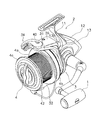
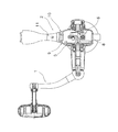
図1から図3において、本発明の一実施形態が採用されたスピニングリールが図示されている。スピニングリールは、主に、リール本体2と、ロータ3と、スプール4とを備えている。リール本体2はハンドル1を有し、釣竿に装着される。ロータ3は、リール本体2の前部に回転自在に装着されている。スプール4は、ロータ3の前部に前後移動自在に装着されている。また、スピニングリールは、ロータ駆動機構5と、オシレーティング機構6とを備える。ロータ駆動機構5は、ハンドル1の回転に連動してロータ3を回転駆動させる。オシレーティング機構6は、ロータ3の回転に連動してスプール4を前後に移動させる。
1 to 3 show a spinning reel in which an embodiment of the present invention is employed. The spinning reel mainly includes a
リール本体2は、ロータ駆動機構5と、オシレーティング機構6とを内部に収容する。図1から図3に示すように、リール本体2は、リールボディ8と、第1蓋部材9と、第2蓋部材10と、T字型の竿取付脚11と、第1カバー部材12と、第2カバー部材13とを備えている。リールボディ8は両側に開口を有するフレーム部材である。第1蓋部材9と第2蓋部材10は、リールボディ8の両側を塞ぐために使用される。第1蓋部材9と第2蓋部材10は、アルミニウム合金製であるが、同様の特徴を有する他の材料を同様に使用してもよい。竿取付脚11は、リールボディ8と一体形成されている。第1カバー部材12と第2カバー部材13は、リールボディ8と、第1蓋部材9と、第2蓋部材10とを後方から覆う。
The
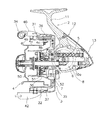
図2に示すように、リールボディ8は、例えばアルミニウム合金製であるが、同様の特徴を有する他の材料を同様に使用してもよい。リールボディ8は、ロータ駆動機構5と、オシレーティング機構6とを収容及び支持するための内部空間8aを有する。図2に示すように、リールボディ8の前面には、円板状の機構支持部8bが形成されている。機構支持部8bには、逆転防止機構50のワンウェイクラッチ51やピニオンギア7等の構成要素が装着されている。
As shown in FIG. 2, the
図2に示すように、ロータ3は、ロータボディ35と、ベールアーム34とを有する。ロータボディ35は、ピニオンギア7を介してリール本体2に回転自在に装着されている。ベールアーム34は、揺動自在にロータボディ35に装着されている。ロータボディ35は、アルミニウム合金製であるが、同様の特徴を有する他の材料を同様に使用してもよい。ロータボディ35は、筒状支持部30と、第1ロータアーム31と、第2ロータアーム32とを有する。筒状支持部30は、ピニオンギア7に固定される。第1ロータアーム31と第2ロータアーム32は、支持部30と所定の間隔を隔てて、支持部30の後端の外周面における対向する位置から前方に延びる。支持部30と、第1ロータアーム31と、第2ロータアーム32とが、ロータボディ35を構成する。例えば、支持部30と、第1ロータアーム31と、第2ロータアーム32とは、アルミニウム合金製であるが、同様の特徴を有する他の材料を同様に使用してもよい。支持部30と、第1ロータアーム31と、第2ロータアーム32とは、ダイカスト成形で形成されているが、同様の結果を実現する他の方法を同様に使用してもよい。図1及び2に示すように、第1ロータアーム31の径方向外周側は、第1カバー部材36で覆われており、第2ロータアーム32の径方向外周は第2カバー部材37で覆われている。また、第1ベール支持部材40と第2ベール支持部材42が、ベールアーム34を構成する。第1ベール支持部材40は、第1ロータアーム31の先端部の外周側に揺動自在に装着されており、第2ベール支持部材42は、第2ロータアーム32の先端部の外周側に揺動自在に装着されている。ベールアーム34は、釣り糸をスプール4にガイドし、巻き付けるために備えられている。ベールアーム34は、糸巻取姿勢と、糸巻取姿勢から反転した糸開放姿勢に揺動自在である。
As shown in FIG. 2, the
図2に示すように、ロータ3は、逆転防止機構50によって糸開放方向への回転を許可・禁止することが可能である。逆転防止機構50は、リールボディ8の機構支持部8bに装着されたローラ型のワンウェイクラッチ51を有する。ワンウェイクラッチ51は、逆転禁止状態と、逆転許可状態とに切り換え可能である。さらに、逆転防止機構50は、ワンウェイクラッチ51の逆転禁止状態と逆転許可状態とを切り換えるための切換操作部52を有する。切換操作部52は、リールボディ8の機構支持部8bの底部において、揺動自在に支持されている。
As shown in FIG. 2, the
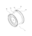
図2に示すように、スプール4は浅底溝を有するように形成されており、糸巻胴部4aと、前フランジ部4bと、筒状スカート部4cとを備える。釣り糸は、糸巻胴部4aの外周に巻き付けられる。前フランジ部4bは、糸巻胴部4aの前端に形成されており、糸巻胴部4aよりも僅かに大径である。筒状スカート部4cは、糸巻胴部4aの後端に形成されており、糸巻胴部4aよりも大径である。
As shown in FIG. 2, the
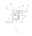
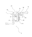
ここで、図4から図7を参照すると、筒状スカート部4cは、貫通孔4eが形成された浅底凹部4dを有する。釣り糸L(図7)をリール本体2に固定するための糸止め20が貫通孔4eに挿入される。糸止め20は黄銅製であるが、同様の特徴を有する他の材料を同様に使用してもよい。図5に示すように、糸止め20は、軸部21と、頭部22とを有する。頭部22は、軸部21の端部と一体形成されているが、軸部21の端部に装着されてもよい。頭部22の外径は、軸部21の直径よりも大径である。頭部22は、軸部21に対向する面22bに形成された環状溝22aを有する。環状溝22aは軸部21と同心円状に配置されている。環状溝22aの外縁部及び頭部22の環状溝22aが形成された面の外縁部は、それぞれフィレット加工(アール面取り加工)されている。
Here, referring to FIGS. 4 to 7, the
図5及び6に示すように、軸部21は、筒状スカート部4cに接続されており、外周面にスナップリング23を装着するための凹部21aを有する。糸止め20を筒状スカート部4cに接続するために、コイルばね24が軸部21に装着され、リング保持部25と、スナップリング23とによって、所定の位置に保持される。コイルばね24は、糸止め20をスプール4の中心に向かって径方向に付勢するために使用される。糸止め20は、スプール4の中心に向かって径方向に付勢されているので、釣り糸は損傷または切断されることなく、頭部22と、環状溝22aと、筒状スカート部4cの凹部4dとの間に保持される。
As shown in FIGS. 5 and 6, the
以上、本発明の一実施形態について説明したが、本発明は上記実施形態に限定されるものではなく、発明の要旨を逸脱しない範囲で種々の変更が可能である。 As mentioned above, although one Embodiment of this invention was described, this invention is not limited to the said embodiment, A various change is possible in the range which does not deviate from the summary of invention.
<他の実施形態>
前記実施形態では、スピニングリールのスプールのスカート部に設けられた糸止めを例示したが、本発明はこれに限定されない。例えば、スピニングリールのスプールの糸巻き胴部や両軸受リールのスプールの糸巻き胴部やフランジ部に設けられる糸止めにも本発明を適用できる。
<Other embodiments>
In the above embodiment, the thread stopper provided in the skirt portion of the spool of the spinning reel is exemplified, but the present invention is not limited to this. For example, the present invention can also be applied to a thread clamp provided on a spool body of a spool of a spinning reel or a spool body or flange of a spool of a dual-bearing reel.
ここで使用された方向を示す用語、即ち、「前方」、「後方」、「上方」、「下方」、「垂直」、「水平」、「径方向」、「横方向」は、他の同様の方向を示す表現とともに、本発明に備えられた装置の方向について言及するものである。 The terminology used here, ie “front”, “back”, “upward”, “downward”, “vertical”, “horizontal”, “radial”, “lateral”, is the same as other The direction of the apparatus provided in the present invention is referred to together with the expression indicating the direction of the apparatus.
したがって、上記用語は、本発明の各態様を記載するために利用されるように、本発明に備えられた装置に関連して解釈すべきである。 Accordingly, the above terms should be construed in connection with the apparatus provided with the present invention, as utilized to describe each aspect of the invention.
本発明を説明するために、特定の実施形態のみが選択されているが、この開示により、特許請求の範囲において定義されるように、本発明の範囲を逸脱しない限りにおいて、様々な変更及び修正を行うことが可能であることは、当業者にとって明白である。さらに、本発明に係る実施形態に関する上記の記載は、例証目的で提供されたものに過ぎず、特許請求の範囲及びそれらの均等物によって定義されるように、本発明を制限するものではない。このように、本発明の範囲は開示された実施例に制限されるものではない。 While only specific embodiments have been selected to describe the present invention, various changes and modifications may be made without departing from the scope of the invention as defined in the claims. It will be apparent to those skilled in the art that Furthermore, the foregoing descriptions of the embodiments according to the present invention are provided for illustrative purposes only, and are not intended to limit the present invention as defined by the claims and their equivalents. Thus, the scope of the invention is not limited to the disclosed embodiments.
4 スプール
4c 筒状スカート部
4d 浅底凹部
4e 貫通孔
20 糸止め
21 軸部
22 頭部
22a 環状溝
24 コイルばね(ばね部材の一例)
25 リング保持部(抜け止め部材の一例)
L 釣り糸
4
25 Ring holder (an example of a retaining member)
L fishing line
Claims (5)
前記釣り用リールに装着される軸部と、
前記頭部における軸部と対向する面に形成され、前記釣り糸係止用の環状溝を有し、前記軸部に設けられ、前記軸部より大きい外径を有する頭部と、
を備えた釣り用リールの糸止め。 A fishing reel thread stopper for stopping a fishing line on a fishing reel,
A shaft portion mounted on the fishing reel;
Formed on a surface of the head facing the shaft portion, having an annular groove for fishing line locking, provided on the shaft portion, and having a larger outer diameter than the shaft portion;
A fishing reel with a thread stopper.
前記頭部は、前記スカート部との間で前記釣り糸を保持する、請求項2に記載のスピニングリールの糸止め。 The fishing reel is a spinning reel having a cylindrical skirt portion on a spool;
3. The spinning reel thread stopper according to claim 2, wherein the head holds the fishing line between the head part and the skirt part.
前記軸部は、前記貫通孔に装着される、請求項3に記載の釣り用リールの糸止め。 The skirt portion has a concave portion with a flat bottom formed on the outer peripheral surface, and a through hole formed in the concave portion,
The fishing reel thread stopper according to claim 3, wherein the shaft portion is attached to the through hole.
請求項4に記載の糸止めと、
前記スカート部の内周面より内周側で前記軸部に抜け止めされたばね受け部材と、
前記ばね受け部材と前記スカート部の内周部の前記貫通孔の周囲との間で配置され、前記糸止めを前記スプールの中心に向かって付勢するばね部材と、
を備えたスピニングリールの糸止め組立体。 A spinning reel thread stopper assembly for securing a fishing line to a spinning reel spool,
A thread stopper according to claim 4;
A spring receiving member that is secured to the shaft portion on the inner peripheral side of the inner peripheral surface of the skirt portion;
A spring member that is disposed between the spring receiving member and the periphery of the through hole in the inner peripheral portion of the skirt portion, and biases the thread stopper toward the center of the spool;
Spinning reel thread clamp assembly with
Applications Claiming Priority (1)
| Application Number | Priority Date | Filing Date | Title |
|---|---|---|---|
| MYPI20085224 | 2008-12-22 |
Publications (1)
| Publication Number | Publication Date |
|---|---|
| JP2010142220A true JP2010142220A (en) | 2010-07-01 |
Family
ID=42078827
Family Applications (1)
| Application Number | Title | Priority Date | Filing Date |
|---|---|---|---|
| JP2009024437A Pending JP2010142220A (en) | 2008-12-22 | 2009-02-05 | Fish line fastener of fishing reel and the assembly thereof |
Country Status (6)
| Country | Link |
|---|---|
| EP (1) | EP2198706A1 (en) |
| JP (1) | JP2010142220A (en) |
| KR (1) | KR20100073994A (en) |
| CN (1) | CN101755717A (en) |
| SG (1) | SG162663A1 (en) |
| TW (1) | TW201032708A (en) |
Cited By (2)
| Publication number | Priority date | Publication date | Assignee | Title |
|---|---|---|---|---|
| EP2767162A1 (en) | 2013-02-18 | 2014-08-20 | Shimano Components (Malaysia) SDN BHD | Spinning reel line clip and spinning reel spool using the same |
| KR20190080727A (en) * | 2017-12-28 | 2019-07-08 | 가부시키가이샤 시마노 | Line clip for spinning reel, and spool for spinning reel having the line clip |
Families Citing this family (4)
| Publication number | Priority date | Publication date | Assignee | Title |
|---|---|---|---|---|
| AT514425B1 (en) * | 2014-02-18 | 2015-01-15 | Hannes Sommer | Coil for use in fishing |
| JP6994310B2 (en) * | 2017-06-07 | 2022-01-14 | 株式会社シマノ | Fishing reel |
| CN112262828B (en) * | 2020-11-19 | 2024-11-22 | 许一帆 | A positioning and clamping device capable of realizing buffering |
| KR102779494B1 (en) * | 2024-05-31 | 2025-03-12 | 주식회사 모넥스코리아 | Fishing line clip device for fishing reel |
Family Cites Families (5)
| Publication number | Priority date | Publication date | Assignee | Title |
|---|---|---|---|---|
| JPS51104964U (en) | 1975-02-21 | 1976-08-23 | ||
| FR2565067B1 (en) * | 1984-06-01 | 1987-03-20 | Mitchell Sports | WIRE HANGING DEVICE FOR FISHING REEL |
| JPS61110766U (en) | 1984-12-26 | 1986-07-14 | ||
| US4883238A (en) * | 1988-12-23 | 1989-11-28 | The Orvis Company, Inc. | Fly fishing reel with a line retainer |
| JP4926823B2 (en) * | 2007-05-24 | 2012-05-09 | グローブライド株式会社 | Fishing reel |
-
2009
- 2009-02-05 JP JP2009024437A patent/JP2010142220A/en active Pending
- 2009-11-26 SG SG200907906-2A patent/SG162663A1/en unknown
- 2009-11-30 TW TW098140821A patent/TW201032708A/en unknown
- 2009-12-10 KR KR1020090122226A patent/KR20100073994A/en not_active Withdrawn
- 2009-12-18 CN CN200910261612A patent/CN101755717A/en active Pending
- 2009-12-21 EP EP09180242A patent/EP2198706A1/en not_active Withdrawn
Cited By (6)
| Publication number | Priority date | Publication date | Assignee | Title |
|---|---|---|---|---|
| EP2767162A1 (en) | 2013-02-18 | 2014-08-20 | Shimano Components (Malaysia) SDN BHD | Spinning reel line clip and spinning reel spool using the same |
| KR20140103819A (en) | 2013-02-18 | 2014-08-27 | 시마노 컴포넌츠 (말레이지아) 에스디엔. 비에이치디. | Line clip for spinning reel and spool using the same for the spinning reel |
| JP2014155469A (en) * | 2013-02-18 | 2014-08-28 | Shimano Components Malaysia Sdn Bhd | Spinning reel line clip and spinning reel spool using the same |
| KR20190080727A (en) * | 2017-12-28 | 2019-07-08 | 가부시키가이샤 시마노 | Line clip for spinning reel, and spool for spinning reel having the line clip |
| JP2019118270A (en) * | 2017-12-28 | 2019-07-22 | 株式会社シマノ | Line locking tool of spinning reel, and spool for spinning reel having ine locking tool |
| KR102662297B1 (en) | 2017-12-28 | 2024-05-02 | 가부시키가이샤 시마노 | Line clip for spinning reel, and spool for spinning reel having the line clip |
Also Published As
| Publication number | Publication date |
|---|---|
| EP2198706A1 (en) | 2010-06-23 |
| TW201032708A (en) | 2010-09-16 |
| KR20100073994A (en) | 2010-07-01 |
| SG162663A1 (en) | 2010-07-29 |
| CN101755717A (en) | 2010-06-30 |
Similar Documents
| Publication | Publication Date | Title |
|---|---|---|
| JP2010142220A (en) | Fish line fastener of fishing reel and the assembly thereof | |
| JP4926823B2 (en) | Fishing reel | |
| KR102219552B1 (en) | Line clip and spool for a spinning reel using the line clip | |
| KR100485273B1 (en) | Double Bearing Reel | |
| CN103988818B (en) | The reel of the spinning wheel type reel of the line engagement device and use of spinning wheel type reel the line engagement device | |
| KR101048724B1 (en) | Spinning Reel Rotor | |
| JP2014155469A5 (en) | ||
| JP2007006710A (en) | Double bearing reel | |
| JP2010172298A (en) | Spinning reel for fishing | |
| JP2959662B2 (en) | Spinning reel for fishing | |
| TWI731021B (en) | Dual-bearing reel | |
| CN110731318A (en) | Hook holder and fishing reel | |
| JP2019118270A (en) | Line locking tool of spinning reel, and spool for spinning reel having ine locking tool | |
| JP6966900B2 (en) | Double bearing reel spool | |
| US7350729B2 (en) | Rotor assembly for fishing reels | |
| KR102766002B1 (en) | Dual-bearing reel | |
| JP3651743B2 (en) | Spinning reel rotor | |
| JP2003125678A (en) | Rotor for spinning reel | |
| JP2019041699A5 (en) | ||
| JP2018186758A (en) | Double bearing fishing reel | |
| JP2022135299A (en) | Spinning reel for fishing | |
| JP2003289770A (en) | Fishline guide mechanism in spinning reel | |
| JP6227273B2 (en) | Single bearing reel | |
| JP4045001B2 (en) | Fishing reel guide mechanism for spinning reel | |
| JP2004222668A (en) | Spool of spinning reel |