JP2010101231A - Output control device for internal combustion engine - Google Patents
Output control device for internal combustion engine Download PDFInfo
- Publication number
- JP2010101231A JP2010101231A JP2008272725A JP2008272725A JP2010101231A JP 2010101231 A JP2010101231 A JP 2010101231A JP 2008272725 A JP2008272725 A JP 2008272725A JP 2008272725 A JP2008272725 A JP 2008272725A JP 2010101231 A JP2010101231 A JP 2010101231A
- Authority
- JP
- Japan
- Prior art keywords
- acceleration
- upper limit
- limit value
- internal combustion
- combustion engine
- Prior art date
- Legal status (The legal status is an assumption and is not a legal conclusion. Google has not performed a legal analysis and makes no representation as to the accuracy of the status listed.)
- Granted
Links
Images


Abstract
Description
本発明は、変速機を有する内燃機関の出力制御装置に関し、特に内燃機関の加速時における出力を制御するための出力制御装置に関する。 The present invention relates to an output control device for an internal combustion engine having a transmission, and more particularly to an output control device for controlling output during acceleration of the internal combustion engine.
従来のこの種の内燃機関の出力制御装置として、例えば特許文献1に開示されたものが知られている。この出力制御装置では、検出されたアクセル開度とエンジン回転数に応じて、要求トルクを算出する。この要求トルクを制限するために、エンジン回転数に応じて、定常状態トルクリミットを算出する。また、検出された変速機のギヤ段および内燃機関の加速度に応じて、トルク増加量を算出する。そして、内燃機関が加速状態のときに、算出された定常状態トルクリミットおよびトルク増加量に応じて、定常状態トルクリミットを一時的に増加させる。その結果、加速時にトルクの制限が一時的に緩和され、加速に要する時間が短縮される。
As a conventional output control device for this type of internal combustion engine, for example, one disclosed in
以上のように、この内燃機関の出力制御装置では、内燃機関の加速度に依存するトルク増加量によって定常状態トルクリミットを増加させる。しかし、通常、ギヤ段が異なると、得られるトルクが異なるため、加速に要する時間も異なる。例えば、高ギヤ段では、得られるトルクは小さいので、加速に要する時間は長くなる。上述した従来の出力制御装置では、ギヤ段に応じて、トルク増加量の大きさを設定しているにすぎないので、ギヤ段に応じた適切な加速時間を確保できない。このため、例えば、より長い加速時間を要する高ギヤ段では、加速が完了しないうちに、トルクの制限の緩和状態が終了することで、良好な加速感が得られず、ドライバビリティが損なわれるおそれがある。 As described above, in this output control device for an internal combustion engine, the steady state torque limit is increased by the amount of torque increase that depends on the acceleration of the internal combustion engine. However, usually, different gear stages have different torques, so the time required for acceleration also differs. For example, at a high gear stage, the torque obtained is small, so the time required for acceleration is long. In the conventional output control apparatus described above, the magnitude of the torque increase amount is only set according to the gear stage, so that an appropriate acceleration time according to the gear stage cannot be ensured. For this reason, for example, in a high gear stage that requires a longer acceleration time, the acceleration restriction is completed before the acceleration is completed, so that a good acceleration feeling may not be obtained and drivability may be impaired. There is.
本発明は、以上のような課題を解決するためになされたものであり、ギヤ段に応じた適切な加速時間を確保でき、それにより、良好な加速感が得られ、ドライバビリティを向上させることができる内燃機関の出力制御装置を提供することを目的とする。 The present invention has been made to solve the above-described problems, and can ensure an appropriate acceleration time according to the gear stage, thereby obtaining a good acceleration feeling and improving drivability. An object of the present invention is to provide an output control device for an internal combustion engine capable of performing
上記目的を達成するため、請求項1に係る発明は、有段の変速機4に接続され、要求トルクTRQ_REQに基づいて内燃機関3の出力を制御する内燃機関3の出力制御装置であって、内燃機関3の運転状態(実施形態における(以下、本項において同じ)エンジン回転数NE、アクセル開度AP)を検出する運転状態検出手段(ECU2、クランク角センサ6、アクセル開度センサ8)と、検出された内燃機関3の運転状態に応じて、要求トルクTRQ_REQを算出する要求トルク算出手段(ECU2、図3のステップ4、5)と、算出された要求トルクTRQ_REQを制限するための上限値TRQ_LMTBASEを設定する上限値設定手段(ECU2、図4のステップ10)と、変速機4の変速比(ギヤ段NGR)を検出する変速比検出手段(ECU2、クランク角センサ6、出力軸回転数センサ11)と、内燃機関3が加速状態にあるか否かを判定する加速判定手段(ECU2、図5、図6)と、加速判定手段により、内燃機関3が加速状態にあると判定されたときに、検出された変速比に応じて、上限値TRQ_LMTBASEの増大期間(増大時間T_CHG)を設定する増大期間設定手段(ECU2、図5のステップ38、図7)と、設定された増大期間において、上限値TRQ_LMTBASEをより大きな加速時上限値TRQ_LMTに設定する加速時上限値設定手段(ECU2、図4)とを備えることを特徴とする。
In order to achieve the above object, the invention according to
この出力制御装置によれば、検出された内燃機関の運転状態に応じて、要求トルクが算出されるとともに、算出された要求トルクを制限するために、上限値が設定される。また、内燃機関が加速状態にあると判定されたときに、検出された変速機の変速比に応じ、増大期間設定手段によって、上限値の増大期間が設定されるとともに、設定された増大期間において、加速時上限値設定手段により、上限値がより大きな加速時上限値に設定される。これにより、より大きな加速時上限値が上限値として用いられることで、要求トルクの制限が緩和される。また、要求トルクの制限を緩和する増大期間が、変速比に応じて設定されるので、変速比に応じた適切な加速時間を確保でき、それにより、良好な加速感が得られ、ドライバビリティを向上させることができる。 According to this output control device, the required torque is calculated according to the detected operating state of the internal combustion engine, and the upper limit value is set to limit the calculated required torque. Further, when it is determined that the internal combustion engine is in an acceleration state, an increase period of the upper limit value is set by the increase period setting means according to the detected gear ratio of the transmission, and in the set increase period The acceleration upper limit value setting means sets the acceleration upper limit value to a larger acceleration upper limit value. Thereby, the restriction | limiting of request | requirement torque is relieve | moderated by using a larger upper limit at the time of acceleration as an upper limit. In addition, since an increase period that relaxes the restriction on the required torque is set according to the gear ratio, an appropriate acceleration time according to the gear ratio can be secured, thereby providing a good acceleration feeling and drivability. Can be improved.
請求項2に係る発明は、請求項1に記載の内燃機関3の出力制御装置において、増大期間設定手段は、変速比が小さいほど、増大期間をより大きな値に設定することを特徴とする。
The invention according to
前述したように、変速機の変速比が小さいほど、トルクは小さくなり、加速に要する時間は長くなる。本発明によれば、変速比が小さいほど、増大期間をより大きな値に設定することによって、加速時上限値がより長く維持され、要求トルクの制限を緩和する期間が長くなるので、変速比が小さい場合でも、十分な加速時間を確保でき、良好な加速感を得ることができる。 As described above, the smaller the transmission gear ratio, the smaller the torque and the longer the time required for acceleration. According to the present invention, the smaller the gear ratio, the longer the acceleration upper limit value is maintained by setting the increase period to a larger value, and the period during which the restriction on the required torque is relaxed. Even if it is small, a sufficient acceleration time can be secured and a good acceleration feeling can be obtained.
請求項3に係る発明は、請求項1に記載の内燃機関3の出力制御装置において、加速時上限値設定手段は、増大期間の経過後、加速時上限値TRQ_LMTを上限値TRQ_LMTBASEに復帰させるときに、加速時上限値TRQ_LMTを変速比に応じた速度で徐々に減少させることを特徴とする。
According to a third aspect of the present invention, in the output control device for the
この構成によれば、増大期間の終了後、加速時上限値は、徐々に減少し、上限値に復帰する。これにより、加速時上限値を上限値に急激に減少させた場合のトルクの急激な減少によるトルクショックを回避し、良好なドライバビリティを確保することができる。また、加速時上限値の減少速度を、変速比に応じた速度に設定するので、加速時上限値を増大期間に応じた適切な速度で、復帰させることができる。 According to this configuration, after the end of the increase period, the acceleration upper limit value gradually decreases and returns to the upper limit value. As a result, it is possible to avoid a torque shock due to a sudden decrease in torque when the acceleration upper limit value is rapidly reduced to the upper limit value, and to ensure good drivability. In addition, since the reduction speed of the acceleration upper limit value is set to a speed corresponding to the gear ratio, the acceleration upper limit value can be returned at an appropriate speed corresponding to the increase period.
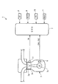
以下、図面を参照しながら、本発明の好ましい実施形態について説明する。図1は、本実施形態による出力制御装置を適用した内燃機関を概略的に示している。この内燃機関(以下「エンジン」という)3は、車両Vに搭載された、例えば直列4気筒タイプのディーゼルエンジンである。 Hereinafter, preferred embodiments of the present invention will be described with reference to the drawings. FIG. 1 schematically shows an internal combustion engine to which the output control apparatus according to the present embodiment is applied. The internal combustion engine (hereinafter referred to as “engine”) 3 is, for example, an in-line four-cylinder type diesel engine mounted on a vehicle V.
図2に示すように、エンジン3は、変速機4を介して、駆動輪である前輪W、Wに接続されている。この変速機4は、前進第1段〜第5段と後進1段の変速段を有する自動変速機である。
As shown in FIG. 2, the
エンジン3には、クランク角センサ6が設けられている(図1参照)。クランク角センサ6は、マグネットロータおよびMREピックアップ(いずれも図示せず)で構成されており、クランクシャフト3cの回転に伴い、パルス信号であるCRK信号およびTDC信号を、ECU2(図1参照)に出力する。
The
このCRK信号は、所定のクランク角(例えば30°)ごとに出力される。ECU2は、CRK信号に基づき、エンジン3の回転数(以下「エンジン回転数」という)NEを算出する。また、TDC信号は、気筒3aのピストン3bが吸気行程開始時のTDC(上死点)付近の所定のクランク角度位置にあることを表す信号であり、本実施形態のような4気筒タイプの場合には、クランク角180°ごとに出力される。
The CRK signal is output every predetermined crank angle (for example, 30 °). The ECU 2 calculates the engine speed (hereinafter referred to as “engine speed”) NE of the
変速機4の出力軸5には、その回転数(以下「出力軸回転数」という)NOUTを検出する出力軸回転数センサ11が設けられている。ECU2は、この出力軸回転数NOUTとエンジン回転数NEに基づいて、変速機4で設定されているギヤ段NGRを算出する。このようにギヤ段NGRが算出されると、変速比も一義的に定まり、ギヤ段NGRが高いほど、変速比はより小さい関係にある。
The
エンジン3のシリンダブロックには、エンジン水温センサ7が設けられている。エンジン水温センサ7は、シリンダブロック内を循環する冷却水の温度であるエンジン水温TWを検出し、それを表す検出信号をECU2に出力する。
An engine
また、ECU2には、アクセル開度センサ8、外気温センサ9および大気圧センサ10が接続されている。アクセル開度センサ8は、図示しないアクセルペダルの操作量(以下「アクセル開度」という)APを検出し、外気温センサ9は外気温TAIRを検出し、大気圧センサ10は大気圧PAを検出し、それらの検出信号はECU2に出力される。
Further, an accelerator opening sensor 8, an outside air temperature sensor 9 and an
ECU2は、CPU、RAM、ROMおよびI/Oインターフェース(いずれも図示せず)などからなるマイクロコンピュータで構成されており、前述した各種のセンサ6〜11の検出信号などに応じて、エンジン3の運転状態を判別するとともに、各種の制御処理を実行する。
The
なお、本実施形態では、ECU2は、運転状態検出手段、要求トルク算出手段、上限値設定手段、変速比検出手段、加速判定手段、増大期間設定手段および加速時上限値設定手段に相当する。
In the present embodiment, the
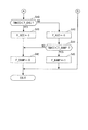
図3は、ECU2で実行される、エンジン3の出力制御処理のメインフローを示す。この出力制御処理は、燃料噴射量を決定するためにエンジン回転数NEとともに用いられる要求トルクTRQ_REQを算出するものである。本処理は、所定の周期Tで実行される。
FIG. 3 shows a main flow of the output control process of the
本処理では、まず、ステップ1(「S1」と図示。以下同じ)において、検出されたエンジン回転数NEおよびアクセル開度APに応じ、所定のマップ(図示せず)を検索することによって、基本要求トルクTRQ_REQBASEを算出する。 In this process, first, in step 1 (illustrated as “S1”, the same applies hereinafter), a basic map is searched by searching a predetermined map (not shown) according to the detected engine speed NE and accelerator pedal opening AP. The required torque TRQ_REQBASE is calculated.
次に、要求トルクTRQ_REQの上限値TRQ_LMTを算出する(ステップ2)。図4は、そのサブルーチンを示す。まず、ステップ10において、エンジン回転数NEに応じて、基本上限値TRQ_LMTBASEを算出する。
Next, an upper limit value TRQ_LMT of the required torque TRQ_REQ is calculated (step 2). FIG. 4 shows the subroutine. First, in
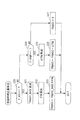
次に、加速判定を行う(ステップ11)。図5および6は、そのサブルーチンを示す。まず、ステップ30〜32において、検出されたエンジン水温TWが、第1および第2所定温度T1、T2で規定される所定の範囲内にあるか否か、検出された外気温TAIRが第3および第4所定温度T3、T4で規定される所定の範囲内にあるか否か、および、検出された大気圧PAが第1および第2所定圧力P1、P2で規定される所定の範囲内にあるか否かを、それぞれ判別する。
Next, acceleration determination is performed (step 11). 5 and 6 show the subroutine. First, in
これらの判別結果のいずれかがNOのときには、エンジン水温TW、外気温TAIRまたは大気圧PAが、加速時において上限値TRQ_LMTを増大させるのに適した条件にないとして、加速判定フラグF_ACCONを「0」にセットし(ステップ50)、アップカウント式の加速タイマのタイマ値(以下「加速タイマ値」という)TMACCを0にリセットし(ステップ51)、本処理を終了する。 When any of these determination results is NO, it is assumed that the engine water temperature TW, the outside air temperature TAIR, or the atmospheric pressure PA is not in a condition suitable for increasing the upper limit value TRQ_LMT during acceleration, and the acceleration determination flag F_ACCON is set to “0”. ”(Step 50), the timer value of the up-counting type acceleration timer (hereinafter referred to as“ acceleration timer value ”) TMMAC is reset to 0 (step 51), and this process ends.
ステップ30〜32の判別結果がいずれもYESで、エンジン水温TW、外気温TAIRおよび大気圧PAが所定の範囲内にあるときには、加速禁止フラグF_FAILが「1」であるか否かを判別する(ステップ33)。
When the determination results in
この加速禁止フラグF_FAILは、アクセル開度センサ8などのセンサ類などが故障していると判定されたときに、加速を禁止すべきとして、「1」にセットされるものである。 This acceleration prohibition flag F_FAIL is set to “1”, indicating that acceleration should be prohibited when it is determined that sensors such as the accelerator opening sensor 8 are malfunctioning.
したがって、ステップ33の判別結果がYESで、故障により加速が禁止されているときには、前記ステップ50および51を実行することにより、加速判定フラグF_ACCONを「0」にセットするとともに、加速タイマ値TMACCを0にリセットし、本処理を終了する。
Therefore, if the determination result in
一方、ステップ33の判別結果がNOのときには、エンジン回転数NEが、第1および第2所定回転数N1、N2で規定される範囲内にあるか否かを判別する(ステップ34)。この判別結果がNOで、エンジン回転数NEが所定の範囲にないときには、エンジン3が加速状態にないとして、前記ステップ50および51を実行した後、本処理を終了する。
On the other hand, when the determination result in
ステップ34の判別結果がYESのときには、アクセル開度APが、所定開度AP_REF以上であるか否かを判別する(ステップ35)。この判別結果がNOで、アクセル開度APが所定開度AP_REFよりも小さいときには、エンジン3が加速状態にないとして、前記ステップ50および51を実行し、本処理を終了する。
If the determination result in the step 34 is YES, it is determined whether or not the accelerator opening AP is a predetermined opening AP_REF or more (step 35). If the determination result is NO and the accelerator opening AP is smaller than the predetermined opening AP_REF, it is determined that the
ステップ35の判別結果がYESで、アクセル開度APが所定開度AP_REF以上であるときには、加速時において上限値TRQ_LMTを増大させる条件が成立しているとして、加速判定フラグF_ACCONが「0」であるか否かを判別する(ステップ36)。 If the determination result in step 35 is YES and the accelerator opening AP is equal to or greater than the predetermined opening AP_REF, it is determined that the condition for increasing the upper limit value TRQ_LMT during acceleration is satisfied, and the acceleration determination flag F_ACCON is “0”. Whether or not (step 36).
この判別結果がYESのとき、すなわち、エンジン3が非加速状態から加速状態に移行した直後であるときには、加速判定フラグF_ACCONを「1」にセットする(ステップ37)。
When the determination result is YES, that is, immediately after the
次に、変速機4のギヤ段NGRに応じ、図7のテーブルを検索することによって、基本上限値TRQ_LMTBASEの増大時間T_CHGを設定する(ステップ38)。 Next, an increase time T_CHG of the basic upper limit value TRQ_LMTBASE is set by searching the table of FIG. 7 according to the gear stage NGR of the transmission 4 (step 38).
このテーブルでは、増大時間T_CHG(TC1〜TC5)は、ギヤ段NGRが高いほど、すなわち変速比が小さいほど、より大きな値に設定されている。これは、変速比が小さいほど、トルクが小さくなり、加速に要する時間が長くなるためである。 In this table, the increase time T_CHG (TC1 to TC5) is set to a larger value as the gear stage NGR is higher, that is, as the gear ratio is smaller. This is because the smaller the gear ratio, the smaller the torque and the longer the time required for acceleration.
次に、ステップ39において、増大させた上限値TRQ_LMTを徐々に減少させ、基本上限値TRQ_LMTBASEに復帰させるための復帰時間T_RAMPを設定する。この復帰時間T_RAMPの設定は、ギヤ段NGRに応じ、図8のテーブルを検索することによって、行われる。このテーブルでは、復帰時間T_RAMP(TR1〜TR5)は、ギヤ段NGRが高いほど、すなわち変速比が小さいほど、より大きな値に設定されている。これは、変速比が小さいほど、加速に要する時間が長くなるため、増大時間T_CHGがより長く設定されるのに対応して、上限値TRQ_LMTをより長い時間をかけて適切に復帰させるためである。
Next, in
上記ステップ39の後にはステップ40に進む。また、前記ステップ36の判別結果がNOのときには、ステップ37〜39をスキップし、直接、ステップ40に進む。
After
このステップ40では、加速タイマ値TMACCが、ステップ38で設定された増大時間T_CHGよりも小さいか否かを判別する。この判別結果がYESのときには、加速時における増大期間中であるため、上限値TRQ_LMTを増大すべきとして、加速時増大フラグF_ACCを「1」にセットする(ステップ41)とともに、復帰フラグF_RAMPを「0」にセットし(ステップ42)、本処理を終了する。
In
一方、ステップ40の判別結果がNOで、加速タイマ値TMACCが増大時間T_CHG以上になったときには、増大期間が終了したとして、加速時増大フラグF_ACCを「0」にセットする(ステップ43)。
On the other hand, if the determination result in
次に、加速タイマ値TMACCが、ステップ39で設定された復帰時間T_RAMPよりも小さいか否かを判別する(ステップ44)。この判別結果がYESのときには、加速時における、復帰期間中であるため、復帰フラグF_RAMPを「1」にセットし(ステップ45)、本処理を終了する。 Next, it is determined whether or not the acceleration timer value TMACC is smaller than the return time T_RAMP set in step 39 (step 44). If the determination result is YES, the return flag F_RAMP is set to “1” because the return period is during acceleration (step 45), and this process ends.
一方、ステップ44の判別結果がNOで、加速タイマ値TMACCが復帰時間T_RAMP以上になったときには、復帰期間が終了したとして、前記ステップ42に進み、復帰フラグF_RAMPを「0」にセットし、本処理を終了する。 On the other hand, if the determination result in step 44 is NO and the acceleration timer value TMMAC is equal to or longer than the return time T_RAMP, it is determined that the return period has ended, the process proceeds to step 42, and the return flag F_RAMP is set to “0”. The process ends.
図4に戻り、前記ステップ11に続くステップ12では、加速時補正量TRQACCを算出する。図9は、そのサブルーチンを示す。まず、ステップ20において、加速時増大フラグF_ACCが「1」であるか否かを判別する。この判別結果がYESで、増大期間中のときには、エンジン回転数NEおよびギヤ段NGRに応じ、所定のマップ(図示せず)を検索することによって、加速時補正量の基本値TRQACC_BASEを算出する(ステップ21)。
Returning to FIG. 4, in step 12 following
次に、ステップ22において、エンジン水温TWに応じ、所定のマップ(図示せず)を検索することによって、水温補正係数KTWを算出する。このマップでは、水温補正係数KTWは、エンジン水温TWが低いほど、エンジン3における摩擦が大きく、より大きな要求トルクTRQ_REQが必要になるため、より大きな値に設定されている。
Next, in step 22, a water temperature correction coefficient KTW is calculated by searching a predetermined map (not shown) according to the engine water temperature TW. In this map, the water temperature correction coefficient KTW is set to a larger value because the lower the engine water temperature TW, the greater the friction in the
次に、ステップ21で算出された基本値TRQACC_BASEに水温補正係数KTWを乗算することによって、加速時補正量TRQACCを算出し(ステップ23)、本処理を終了する。
Next, the acceleration correction amount TRQACC is calculated by multiplying the basic value TRQACC_BASE calculated in
一方、ステップ20の判別結果がNOで、増大期間中でないときには、復帰フラグF_RAMPが「1」であるか否かを判別する(ステップ24)。
On the other hand, when the determination result of
この判別結果がYESのときには、増大期間が終了し、復帰期間に移行しているため、増大した上限値TRQ_LMTを基本上限値TRQ_LMTBASEに復帰させるためのトルク減少量ΔTRQを、次式(1)によって算出する(ステップ25)。

次に、算出されたトルク減少量ΔTRQをステップ23で算出された加速時補正量TRQACCから減算した値を、新たな加速時補正量TRQACCとして設定し(ステップ26)、本処理を終了する。このようなトルク減少量ΔTRQを用いた減算を繰り返し、行うことにより、上限値TRQ_LMTは、徐々に減少し、復帰期間の終了時に基本上限値TRQ_LMTBASEに復帰する。 Next, a value obtained by subtracting the calculated torque reduction amount ΔTRQ from the acceleration correction amount TRQACC calculated in step 23 is set as a new acceleration correction amount TRQACC (step 26), and this process is terminated. By repeatedly performing such subtraction using the torque decrease amount ΔTRQ, the upper limit value TRQ_LMT gradually decreases and returns to the basic upper limit value TRQ_LMTBASE at the end of the return period.
前記ステップ24の判別結果がNOのときには、増大期間中および復帰期間中のいずれでもないため、加速時補正量TRQACCを0に設定し(ステップ27)、本処理を終了する。
When the determination result in
図4に戻り、ステップ13では、ステップ10で算出された基本上限値TRQ_LMTBASEに、前記ステップ12で算出された加速時補正量TRQACCを加算することによって、上限値TRQ_LMTを算出し、本処理を終了する。
Returning to FIG. 4, in step 13, the upper limit value TRQ_LMT is calculated by adding the acceleration correction amount TRQACC calculated in step 12 to the basic upper limit value TRQ_LMTBASE calculated in
図3に戻り、ステップ3〜5では、前記ステップ2で算出された上限値TRQ_LMTを用いて、基本要求トルクTRQ_REQBASEのリミット処理を行う。まず、ステップ3では、基本要求トルクTRQ_REQBASEが上限値TRQ_LMTよりも大きいか否かを判別する。この判別結果がNOで、TRQ_REQBASE≦TRQ_LMTのときには、基本要求トルクTRQ_REQBASEを要求トルクTRQ_REQとして設定し(ステップ4)、本処理を終了する。
Returning to FIG. 3, in
一方、ステップ3の判別結果がYESで、TRQ_REQBASE>TRQ_LMTのときには、上限値TRQ_LMTを要求トルクTRQ_REQとして設定し(ステップ5)、本処理を終了する。
On the other hand, if the determination result in
以上のように算出された要求トルクTRQ_REQは、エンジン回転数NEとともにエンジン3に噴射される燃料噴射量を決定するために用いられ、それによりエンジン3の出力が制御される。
The required torque TRQ_REQ calculated as described above is used to determine the fuel injection amount injected into the
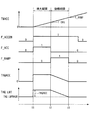
図10は、これまでに説明した出力制御処理によって得られる動作例を示す。この例では、時点t1以前においては、エンジン3の加速判定条件が成立しておらず、このため、加速時補正量TRQACCは0であり、要求トルクTRQ_REQは基本上限値TRQ_LMTBASEに設定されている。
FIG. 10 shows an operation example obtained by the output control processing described so far. In this example, the acceleration determination condition of the
この状態から、加速判定条件が成立すると(t1)、加速判定フラグF_ACCONが「1」にセットされ、加速タイマの計時が開始されるとともに、ギヤ段NGRに応じ、増大時間T_CHGおよび復帰時間T_RAMPが設定される(ステップ38、39)。また、加速時増大フラグF_ACCが「1」にセットされ(ステップ41)、増大期間に移行する。
From this state, when the acceleration determination condition is satisfied (t1), the acceleration determination flag F_ACCON is set to “1”, the acceleration timer starts counting, and the increase time T_CHG and the return time T_RAMP are set according to the gear stage NGR. It is set (
この増大期間では、加速時補正量TRQACCが、基本値TRQACC_BASEおよび水温補正係数KTWに応じて設定され(ステップ23)、基本上限値TRQ_LMTBASEに加算されることによって、上限値TRQ_LMTが算出される(ステップ13)。これにより、増大期間では、要求トルクTRQ_REQの上限値TRQ_LMTは、より大きな値に設定される。 In this increase period, the acceleration correction amount TRQACC is set according to the basic value TRQACC_BASE and the water temperature correction coefficient KTW (step 23), and is added to the basic upper limit value TRQ_LMTBASE, thereby calculating the upper limit value TRQ_LMT (step). 13). Thereby, in the increase period, upper limit value TRQ_LMT of required torque TRQ_REQ is set to a larger value.
その後、加速タイマ値TMACCが増大時間T_CHGに達したとき(ステップ40:NO)に(t2)、加速時増大フラグF_ACCが「0」にセットされ(ステップ43)、増大期間が終了するとともに、復帰フラグF_RAMPが「1」にセットされ(ステップ45)、復帰期間に移行する。 Thereafter, when the acceleration timer value TMACC reaches the increase time T_CHG (step 40: NO) (t2), the acceleration increase flag F_ACC is set to “0” (step 43), the increase period ends and the return is made. The flag F_RAMP is set to “1” (step 45), and the process proceeds to the return period.
この復帰期間では、制御処理ごとに、その開始時の加速時補正量TRQACCからトルク減少量ΔTRQが減算されることによって、加速時補正量TRQACCが徐々に減少する。それに伴い、上限値TRQ_LMTも徐々に減少する。 In this return period, the acceleration correction amount TRQACC gradually decreases by subtracting the torque reduction amount ΔTRQ from the acceleration correction amount TRQACC at the start of each control process. Along with this, the upper limit value TRQ_LMT gradually decreases.
その後、加速タイマ値TMACCが復帰時間T_RAMPに達したとき(ステップ44:NO)に(t3)、復帰フラグF_RAMPが「0」にセットされ(ステップ42)、復帰期間が終了する。その時点では、加速時補正量TRQACCが0になっていることで、上限値TRQ_LMTは基本上限値TRQ_LMTBASEに復帰している。 Thereafter, when the acceleration timer value TMACC reaches the return time T_RAMP (step 44: NO) (t3), the return flag F_RAMP is set to “0” (step 42), and the return period ends. At that time, since the acceleration correction amount TRQACC is 0, the upper limit value TRQ_LMT has returned to the basic upper limit value TRQ_LMTBASE.
以上のように、本実施形態によれば、エンジン3の運転状態に応じて基本要求トルクTRQ_REQBASEが算出されるとともに、算出された基本要求トルクTRQ_REQBASEを制限するために、基本上限値TRQ_LMTBASEが設定される。また、エンジン3が加速状態にあると判定されたときに、変速機4のギヤ段NGRに応じ、基本上限値TRQ_LMTBASEの増大時間T_CHGが設定される。そして、そのように設定された増大期間では、加速時補正量TRQACCがより大きな値に設定されることで、上限値TRQ_LMTがより大きな値に設定される。このように、より大きな上限値TRQ_LMTが用いられることで、要求トルクTRQ_REQの制限が緩和される。また、要求トルクTRQ_REQの制限を緩和する増大時間T_CHGが、ギヤ段NGRに応じて設定されるので、ギヤ段NGRに応じた適切な加速時間を確保でき、それにより、良好な加速感が得られ、ドライバビリティを向上させることができる。
As described above, according to the present embodiment, the basic required torque TRQ_REQBASE is calculated according to the operating state of the
また、増大期間の終了後の復帰期間では、上限値TRQ_LMTが、トルク減少量ΔTRQによって徐々に減少し、復帰期間の終了時に、基本上限値TRQ_LMTBASEに復帰する。これにより、トルクの急激な減少によるトルクショックを回避し、良好なドライバビリティを確保することができる。また、ギヤ段NGRが高いほど、すなわち変速比が小さいほど、復帰時間T_CHGを長く設定するので、増大時間T_CHGがより長く設定されるのに対応して、上限値TRQ_LMTをより長い時間をかけて適切に復帰させることができる。 In the return period after the end of the increase period, the upper limit value TRQ_LMT is gradually decreased by the torque decrease amount ΔTRQ, and returns to the basic upper limit value TRQ_LMTBASE at the end of the return period. As a result, it is possible to avoid a torque shock due to a rapid decrease in torque and to ensure good drivability. Further, the higher the gear stage NGR, that is, the smaller the gear ratio, the longer the return time T_CHG is set. Accordingly, the upper limit value TRQ_LMT is set to take a longer time corresponding to the increase time T_CHG being set longer. It can be restored properly.
なお、本発明は、説明した実施形態に限定されることなく、種々の態様で実施することができる。例えば、実施形態では、基本上限値TRQ_LMTBASEに加速時補正量TRQACCを加算することによって、上限値TRQ_LMTを算出したが、これに代えて、加速時補正量TRQACCを含む上限値TRQ_LMTを直接、算出してもよい。 In addition, this invention can be implemented in various aspects, without being limited to the described embodiment. For example, in the embodiment, the upper limit value TRQ_LMT is calculated by adding the acceleration correction amount TRQACC to the basic upper limit value TRQ_LMTBASE, but instead, the upper limit value TRQ_LMT including the acceleration correction amount TRQACC is directly calculated. May be.
また、実施形態では、復帰時間T_RAMPを設定し、復帰期間の終了時に加速時補正量TRQACCが0になるようにトルク減少量ΔTRQを逆算しているが、先に、ギヤ段NGRに応じてトルク減少量ΔTRQを決定し、上限値TRQ_LMTが基本上限値TRQ_LMTBASEに等しくなったときに、復帰期間が終了するようにしてもよい。また、トルク減少量ΔTRQを、ギヤ段NGRとは無関係に、所定値に設定してもよい。 Further, in the embodiment, the return time T_RAMP is set, and the torque decrease amount ΔTRQ is calculated backward so that the acceleration correction amount TRQACC becomes 0 at the end of the return period. However, first, the torque is reduced according to the gear stage NGR. The decrease amount ΔTRQ may be determined, and the return period may end when the upper limit value TRQ_LMT becomes equal to the basic upper limit value TRQ_LMTBASE. Further, the torque reduction amount ΔTRQ may be set to a predetermined value regardless of the gear stage NGR.
さらに、実施形態では、変速機4のギヤ段NGRを、出力軸回転数NOUTおよびエンジン回転数NEに基づいて算出したが、その検出手法は任意であり、例えば、センサを用い、ギヤ段NGRを直接、検出してもよい。 Further, in the embodiment, the gear stage NGR of the transmission 4 is calculated based on the output shaft rotational speed NOUT and the engine rotational speed NE. However, the detection method is arbitrary, for example, a sensor is used to calculate the gear stage NGR. It may be detected directly.
また、実施形態では、エンジン3に接続された変速機が、有段の変速機4であるが、無段の変速機でもよい。この場合にも、例えば、エンジン回転数NEと出力軸回転数NOUTに応じて変速比を算出するとともに、算出された変速比に応じ、増大時間T_CHGおよび復帰時間T_RAMPが、それぞれの所定のテーブルを検索することによって設定される。このような構成により、前述した実施形態による効果を同様に得ることができる。
In the embodiment, the transmission connected to the
また、実施形態は、本発明を車両に搭載されたディーゼルエンジンに適用した例であるが、本発明は、これに限らず、ディーゼルエンジン以外のガソリンエンジンなどの各種エンジンに適用してもよく、また、車両用以外のエンジン、例えば、クランク軸を鉛直に配置した船外機などのような船舶推進機用エンジンにも適用可能である。その他、本発明の趣旨の範囲内で、細部の構成を適宜、変更することが可能である。 Moreover, although embodiment is an example which applied this invention to the diesel engine mounted in the vehicle, this invention is not restricted to this, You may apply to various engines, such as gasoline engines other than a diesel engine, Further, the present invention can also be applied to engines other than those for vehicles, for example, marine vessel propulsion engines such as outboard motors having a crankshaft arranged vertically. In addition, it is possible to appropriately change the detailed configuration within the scope of the gist of the present invention.
1 出力制御装置
2 ECU(運転状態検出手段、要求トルク算出手段、上限値設定手段、変速比検出手段、加速判定手段、増大期間設定手段、加速時上限値設定手段)
3 エンジン(内燃機関)
6 クランク角センサ(運転状態検出手段、変速比検出手段)
8 アクセル開度センサ(運転状態検出手段)
11 出力軸回転数センサ(変速比検出手段)
TRQ_REQ 要求トルク
NE エンジン回転数
AP アクセル開度
TRQ_LMTBASE 基本上限値(上限値)
NGR ギヤ段(変速比)
T_CHG 増大時間
TRQ_LMT 上限値(加速時上限値)
DESCRIPTION OF
3 Engine (Internal combustion engine)
6 Crank angle sensor (driving condition detecting means, gear ratio detecting means)
8 Accelerator opening sensor (operating state detection means)
11 Output shaft rotational speed sensor (speed ratio detecting means)
TRQ_REQ Required torque
NE engine speed
AP accelerator opening TRQ_LMTBASE Basic upper limit (upper limit)
NGR gear stage (speed ratio)
T_CHG increase time TRQ_LMT upper limit (acceleration upper limit)
Claims (3)
前記内燃機関の運転状態を検出する運転状態検出手段と、
当該検出された内燃機関の運転状態に応じて、前記要求トルクを算出する要求トルク算出手段と、
当該算出された要求トルクを制限するための上限値を設定する上限値設定手段と、
前記変速機の変速比を検出する変速比検出手段と、
前記内燃機関が加速状態にあるか否かを判定する加速判定手段と、
当該加速判定手段により、前記内燃機関が加速状態にあると判定されたときに、前記検出された変速比に応じて、前記上限値の増大期間を設定する増大期間設定手段と、
当該設定された増大期間において、前記上限値をより大きな加速時上限値に設定する加速時上限値設定手段と、
を備えることを特徴とする内燃機関の出力制御装置。 An output control device for an internal combustion engine that is connected to a transmission and controls the output of the internal combustion engine based on a required torque,
An operating state detecting means for detecting an operating state of the internal combustion engine;
Requested torque calculating means for calculating the required torque according to the detected operating state of the internal combustion engine;
An upper limit setting means for setting an upper limit for limiting the calculated required torque;
Gear ratio detecting means for detecting a gear ratio of the transmission;
Acceleration determining means for determining whether or not the internal combustion engine is in an acceleration state;
An increase period setting means for setting an increase period of the upper limit value according to the detected gear ratio when the acceleration determination means determines that the internal combustion engine is in an acceleration state;
An acceleration upper limit value setting means for setting the upper limit value to a larger acceleration upper limit value in the set increase period;
An output control device for an internal combustion engine, comprising:
Priority Applications (1)
| Application Number | Priority Date | Filing Date | Title |
|---|---|---|---|
| JP2008272725A JP5058124B2 (en) | 2008-10-23 | 2008-10-23 | Output control device for internal combustion engine |
Applications Claiming Priority (1)
| Application Number | Priority Date | Filing Date | Title |
|---|---|---|---|
| JP2008272725A JP5058124B2 (en) | 2008-10-23 | 2008-10-23 | Output control device for internal combustion engine |
Publications (2)
| Publication Number | Publication Date |
|---|---|
| JP2010101231A true JP2010101231A (en) | 2010-05-06 |
| JP5058124B2 JP5058124B2 (en) | 2012-10-24 |
Family
ID=42292091
Family Applications (1)
| Application Number | Title | Priority Date | Filing Date |
|---|---|---|---|
| JP2008272725A Expired - Fee Related JP5058124B2 (en) | 2008-10-23 | 2008-10-23 | Output control device for internal combustion engine |
Country Status (1)
| Country | Link |
|---|---|
| JP (1) | JP5058124B2 (en) |
Citations (8)
| Publication number | Priority date | Publication date | Assignee | Title |
|---|---|---|---|---|
| JPH1089129A (en) * | 1996-09-18 | 1998-04-07 | Toyota Motor Corp | Fuel injection device |
| JPH10339177A (en) * | 1997-06-11 | 1998-12-22 | Honda Motor Co Ltd | Controller for vehicle engine |
| JPH11101142A (en) * | 1997-09-26 | 1999-04-13 | Mitsubishi Motors Corp | Output torque control device for vehicle |
| JP2000027684A (en) * | 1998-07-09 | 2000-01-25 | Mitsubishi Motors Corp | Fuel injection control device for engine |
| JP2000303893A (en) * | 1999-04-26 | 2000-10-31 | Mitsubishi Motors Corp | Torque control device for internal combustion engine |
| JP2005083373A (en) * | 2003-09-09 | 2005-03-31 | Hyundai Motor Co Ltd | Torque control method of internal combustion engine |
| JP2006170116A (en) * | 2004-12-17 | 2006-06-29 | Nissan Motor Co Ltd | Prime mover torque control device |
| JP2007263093A (en) * | 2006-03-30 | 2007-10-11 | Toyota Motor Corp | Torque control device of internal combustion engine |
-
2008
- 2008-10-23 JP JP2008272725A patent/JP5058124B2/en not_active Expired - Fee Related
Patent Citations (8)
| Publication number | Priority date | Publication date | Assignee | Title |
|---|---|---|---|---|
| JPH1089129A (en) * | 1996-09-18 | 1998-04-07 | Toyota Motor Corp | Fuel injection device |
| JPH10339177A (en) * | 1997-06-11 | 1998-12-22 | Honda Motor Co Ltd | Controller for vehicle engine |
| JPH11101142A (en) * | 1997-09-26 | 1999-04-13 | Mitsubishi Motors Corp | Output torque control device for vehicle |
| JP2000027684A (en) * | 1998-07-09 | 2000-01-25 | Mitsubishi Motors Corp | Fuel injection control device for engine |
| JP2000303893A (en) * | 1999-04-26 | 2000-10-31 | Mitsubishi Motors Corp | Torque control device for internal combustion engine |
| JP2005083373A (en) * | 2003-09-09 | 2005-03-31 | Hyundai Motor Co Ltd | Torque control method of internal combustion engine |
| JP2006170116A (en) * | 2004-12-17 | 2006-06-29 | Nissan Motor Co Ltd | Prime mover torque control device |
| JP2007263093A (en) * | 2006-03-30 | 2007-10-11 | Toyota Motor Corp | Torque control device of internal combustion engine |
Also Published As
| Publication number | Publication date |
|---|---|
| JP5058124B2 (en) | 2012-10-24 |
Similar Documents
| Publication | Publication Date | Title |
|---|---|---|
| JP2007224727A (en) | Control device of internal combustion engine | |
| JP2002276447A (en) | Control device for internal combustion engine | |
| JP2004150424A (en) | Controlling device of internal combustion engine | |
| JP2007192082A (en) | Estimated torque calculation device for internal combustion engine mounted on vehicle | |
| EP2096285A2 (en) | Torque calculation method for engine | |
| JP4799654B2 (en) | Power generation control device for internal combustion engine | |
| JP2010185433A (en) | Catalyst warming-up control device for internal combustion engine | |
| JP2009167889A (en) | Control method of internal combustion engine | |
| JP5058124B2 (en) | Output control device for internal combustion engine | |
| JP2010185425A (en) | Control device of internal combustion engine | |
| US20030094157A1 (en) | Power output control system for internal combustion engine | |
| JP5071349B2 (en) | Control device for vehicle with clutch mechanism | |
| JP4120614B2 (en) | Start control device for internal combustion engine | |
| JP5141673B2 (en) | Idle stop control device for internal combustion engine | |
| JP2010264817A (en) | Control device of hybrid vehicle | |
| JP2004183615A (en) | Controlling device of internal combustion engine | |
| JP2011157948A (en) | Fuel injection control device | |
| JP4788277B2 (en) | Control device for internal combustion engine for automobile | |
| JP4738473B2 (en) | Torque control device for internal combustion engine | |
| JP6153342B2 (en) | Control device for internal combustion engine | |
| JP2018189023A (en) | Control device of vehicle | |
| JP5400672B2 (en) | Control device for hybrid vehicle | |
| JP4216309B2 (en) | Control device for internal combustion engine | |
| JP2009216037A (en) | Fuel injection control device of internal combustion engine | |
| JP5047012B2 (en) | Fuel injection control device for internal combustion engine |
Legal Events
| Date | Code | Title | Description |
|---|---|---|---|
| A621 | Written request for application examination |
Free format text: JAPANESE INTERMEDIATE CODE: A621 Effective date: 20101125 |
|
| A131 | Notification of reasons for refusal |
Free format text: JAPANESE INTERMEDIATE CODE: A131 Effective date: 20120131 |
|
| A977 | Report on retrieval |
Free format text: JAPANESE INTERMEDIATE CODE: A971007 Effective date: 20120131 |
|
| A521 | Written amendment |
Free format text: JAPANESE INTERMEDIATE CODE: A523 Effective date: 20120328 |
|
| TRDD | Decision of grant or rejection written | ||
| A01 | Written decision to grant a patent or to grant a registration (utility model) |
Free format text: JAPANESE INTERMEDIATE CODE: A01 Effective date: 20120703 |
|
| A01 | Written decision to grant a patent or to grant a registration (utility model) |
Free format text: JAPANESE INTERMEDIATE CODE: A01 |
|
| A61 | First payment of annual fees (during grant procedure) |
Free format text: JAPANESE INTERMEDIATE CODE: A61 Effective date: 20120731 |
|
| FPAY | Renewal fee payment (event date is renewal date of database) |
Free format text: PAYMENT UNTIL: 20150810 Year of fee payment: 3 |
|
| R150 | Certificate of patent or registration of utility model |
Ref document number: 5058124 Country of ref document: JP Free format text: JAPANESE INTERMEDIATE CODE: R150 Free format text: JAPANESE INTERMEDIATE CODE: R150 |
|
| LAPS | Cancellation because of no payment of annual fees |