JP2010100397A - Interleaf separator - Google Patents
Interleaf separator Download PDFInfo
- Publication number
- JP2010100397A JP2010100397A JP2008273247A JP2008273247A JP2010100397A JP 2010100397 A JP2010100397 A JP 2010100397A JP 2008273247 A JP2008273247 A JP 2008273247A JP 2008273247 A JP2008273247 A JP 2008273247A JP 2010100397 A JP2010100397 A JP 2010100397A
- Authority
- JP
- Japan
- Prior art keywords
- slip sheet
- interleaf
- glass panel
- sandwiching
- plate material
- Prior art date
- Legal status (The legal status is an assumption and is not a legal conclusion. Google has not performed a legal analysis and makes no representation as to the accuracy of the status listed.)
- Granted
Links
Images


Abstract
Description
本発明は、合紙梱包されたガラス基板等の板材の表面から合紙を分離するための合紙分離装置に関する。 The present invention relates to a slip sheet separating device for separating slip sheets from the surface of a plate material such as a glass substrate packed with slip sheets.
ガラス基板等の板材を運搬する際、一度に大量に運搬でき、且つ、ガラス基板同士の接触による傷を防止できる梱包方法として、ガラス基板の間に合紙を挟んで梱包する、いわゆる合紙梱包が知られている。合紙梱包されたガラス基板を解荷するときには、合紙をガラス基板から分離する必要がある。 When transporting plate materials such as glass substrates, so-called interleaf packaging is possible as a packaging method that can transport a large amount at a time and prevent scratches due to contact between the glass substrates by sandwiching interleaf sheets between glass substrates. It has been known. When unloading a glass substrate packed with slip paper, it is necessary to separate the slip paper from the glass substrate.
例えば、特許文献1に示されている合紙分離装置は、回動可能に設けられた一対の保持片と、保持片を進退自在に支持する支持部材とを有し、以下のような手順で合紙をガラス基板から分離している。
(1)支持部材を伸長させて保持片をガラス基板に近づけ、ガラス基板表面の合紙と当接する手前で停止させる。
(2)保持片を回動させて合紙を掴む。
(3)支持部材を退避させ、合紙を基板から剥離する。
For example, the slip sheet separating device disclosed in
(1) The supporting member is extended to bring the holding piece closer to the glass substrate and stopped just before contacting the slip sheet on the surface of the glass substrate.
(2) The holding piece is rotated to grip the slip sheet.
(3) The support member is retracted, and the slip sheet is peeled from the substrate.
しかし、上記特許文献1の合紙分離装置では、斜めに立設配置したガラス基板に対して、水平方向から保持片を近づけているため、一対の保持片を同時にガラス基板に当接させることができず、ガラス基板に付着した合紙を確実に掴むことができない恐れがある。
However, in the slip sheet separating apparatus disclosed in
また、保持片をガラス基板表面の合紙と接触する手前で停止させた状態で、保持片を回動させて合紙を挟持するため、保持片で合紙を掴むことのできる領域(掴み代)が小さくなり、合紙を掴み損ねる恐れがある。 In addition, since the holding piece is stopped before it comes into contact with the slip sheet on the surface of the glass substrate, the holding piece is rotated to pinch the slip sheet. ) Will be small, and there is a risk of failing to grasp the slip.
さらに、支持部材を停止させた状態で保持片を回動させるため、保持片の先端部が板材に当接することにより保持片の回動が妨げられる。そのまま保持片の回動を続けると、保持片の先端部が合紙に強く押し付けられることとなり、板材を傷つける恐れがある。 Furthermore, since the holding piece is rotated while the support member is stopped, the tip of the holding piece comes into contact with the plate member, thereby preventing the holding piece from rotating. If the rotation of the holding piece is continued as it is, the tip of the holding piece will be strongly pressed against the interleaf and the plate material may be damaged.
本発明の課題は、板材を傷つけることなく、板材の表面から合紙を確実に分離することのできる合紙分離装置を提供することにある。 An object of the present invention is to provide an interleaving paper separation device that can reliably separate interleaving paper from the surface of the plate material without damaging the plate material.
前記課題を解決するために、本発明は、合紙梱包された板材の表面から合紙を分離する合紙分離装置であって、回動可能な一対の挟持片からなり、先端部を開閉可能な挟持部材と、挟持部材を板材と直交する方向にスライドさせるスライド機構とを有し、挟持部材の先端部を開いた状態で各挟持片の先端部を板材の表面に付着した合紙に当接させ、挟持部材を板材から離反させながら挟持部材の先端部を閉じて合紙を掴むようにしたものである。 In order to solve the above-mentioned problems, the present invention is a slip sheet separating device that separates slip sheets from the surface of a sheet material packed with slip sheets, and is composed of a pair of pivotable clamping pieces that can be opened and closed. A sandwiching member and a slide mechanism that slides the sandwiching member in a direction perpendicular to the plate member, and with the leading end portion of the sandwiching member open, the leading end portion of each sandwiching piece is applied to the slip sheet attached to the surface of the plate member. The front end of the holding member is closed while the holding member is moved away from the plate material, and the slip sheet is gripped.
このように、本発明では、挟持部材を板材と直交する方向でスライドさせるため、一対の挟持片を同時に合紙に当接させることができる。また、挟持部材の先端部を開いた状態で各挟持片を合紙に当接させることにより、挟持部材による合紙の掴み代を大きく取ることができ、合紙を確実に掴むことができる。さらに、挟持部材の先端部を板材表面の合紙に当接させ、挟持部材を板材から離反する方向にスライドさせながら挟持部材の先端部を閉じることにより、各挟持片の先端部が板材に強く押し付けられることがないため、板材を傷つける恐れを回避できる。 As described above, in the present invention, since the sandwiching member is slid in the direction orthogonal to the plate material, the pair of sandwiching pieces can be simultaneously brought into contact with the slip sheet. Further, by bringing the holding pieces into contact with the interleaving paper in a state where the leading end portion of the interposing member is opened, a large margin for gripping the interleaving paper by the interposing member can be obtained, and the interleaving paper can be securely grasped. Furthermore, the front end of each clamping piece is made strong against the plate by closing the front end of the clamping member while bringing the front end of the clamping member into contact with the slip sheet on the surface of the plate and sliding the clamping member away from the plate. Since it is not pressed, the risk of damaging the plate material can be avoided.
各挟持片に、挟持部材を開いた状態で板材の表面の合紙に面接触する第1平面部を形成すれば、挟持片と合紙との接触面積を拡大して両者の摩擦力を増大することができるため、挟持部材で合紙をより確実に掴むことができる。また、各挟持片に、挟持部材を閉じた状態で互いに面接触する第2平面部を形成すれば、各挟持片の第2平面部同士で合紙を挟持することができるため、挟持部材で合紙を確実に保持することができる。 If each holding piece is formed with a first flat portion that comes into surface contact with the slip sheet on the surface of the plate with the holding member opened, the contact area between the sandwich piece and the slip sheet is increased to increase the frictional force between them. Therefore, the interleaving paper can be more reliably grasped by the sandwiching member. In addition, if the second flat portions that are in surface contact with each other in a state in which the holding member is closed are formed on each holding piece, the slip sheet can be held between the second flat portions of each holding piece. Interleaving paper can be securely held.
ところで、合紙梱包された板材の積層体から板材を一枚ずつ次工程に移送する場合、移送される板材に連れられて合紙が積層体から分離することがある。挟持部材で合紙を掴む前に積層体から合紙が分離すると、挟持部材で合紙を掴めなくなったり、分離した合紙が他の装置に干渉する恐れがある。かかる不具合を防止するため、板材から合紙が分離することを防止する分離防止手段を設ける場合がある。一方、挟持部材で合紙を掴んで分離する際は、分離防止手段を解除して積層体から合紙を分離できる状態とする必要がある。従って、上記の合紙分離装置では、挟持部材の先端部が合紙に当接するまでは分離防止手段で合紙を板材に付着させた状態とし、挟持部材を合紙に当接させた後に分離防止手段を解除すればよい。 By the way, when a board | plate material is transferred to the following process one sheet at a time from the laminated body of the board | plate material packaged in the interleaf paper, the interleaf paper may be separated from the laminated body along with the transferred board material. If the interleaving paper is separated from the laminated body before the interleaving paper is grasped by the sandwiching member, the interleaving paper may not be grasped by the interposing member, or the separated interleaving paper may interfere with other devices. In order to prevent such a problem, a separation preventing means for preventing separation of the slip sheet from the plate material may be provided. On the other hand, when gripping and separating the slip sheet with the sandwiching member, it is necessary to release the separation preventing means so that the slip sheet can be separated from the laminate. Therefore, in the above-described slip sheet separating device, the slip sheet is adhered to the plate material by the separation preventing means until the leading end of the sandwiching member comes into contact with the slip sheet, and is separated after the sandwich member is brought into contact with the slip sheet. The prevention means may be canceled.
以上のように、本発明の合紙分離装置によれば、板材を傷つけることなく、板材から合紙を確実に分離することができる。 As described above, according to the slip sheet separating apparatus of the present invention, the slip sheet can be reliably separated from the plate material without damaging the plate material.
以下、本発明の実施形態を図面に基づいて説明する。 Hereinafter, embodiments of the present invention will be described with reference to the drawings.
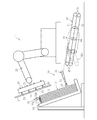
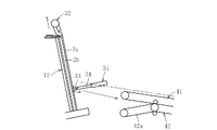
図1に、合紙梱包された板材(本実施形態ではガラスパネル2)を解荷するための解荷装置1を示す。ガラスパネル2は合紙3を間に挟んで積層され、この積層体12がパレット10の上に傾斜した状態で立設される。解荷装置1は、積層体12からガラスパネル2を一枚ずつ取り上げて次工程へ移送するパネル移送装置20と、ガラスパネル2から合紙3を分離する合紙分離装置30と、分離した合紙3を排紙パレット(図示省略)へ搬送する搬送装置40とを備える。尚、以下では、説明の便宜上、積層体12の積層方向において、移送される順番の早い側(すなわちパネル移送装置20側)を表側と言う。
FIG. 1 shows an
パネル移送装置20は、ガラスパネル2の表面に吸着する複数の吸着部21と、各吸着部21を支持する支持部22と、支持部22を移動させるアーム部23とを有する。各吸着部21は、支持部22に対して、ガラスパネル2と直交する方向にスライド可能に設けられる。
The
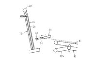
合紙分離装置30は、合紙3をガラスパネル2から剥離する合紙剥離機構31と、積層体12の上方に設けられた分離防止手段としての押さえ機構32とを有する。合紙剥離機構31は、合紙3を挟持するための挟持部材33と、挟持部材33を開閉させる開閉機構(図示省略)と、各挟持部材33をガラスパネル2と直交する方向にスライドさせる第1スライド機構としての駆動シリンダ34と、挟持部材33をガラスパネル2と搬送装置40との間でスライドさせる第2スライド機構(図示省略)とで構成される。合紙剥離機構31には、開閉機構、駆動シリンダ34、及び第2スライド機構を制御する制御部が設けられ、この制御部の指令に従って挟持部材33の開閉及びスライドが制御される。挟持部材33は、ガラスパネル2の幅方向(図1の紙面と直交する方向)等間隔位置の複数箇所(例えば6箇所)に設けられ、幅方向に延びた連結軸(図示省略)で一体化されている。第2スライド機構は、複数の挟持部材33の連結軸を、搬送装置40の合紙搬送方向と平行な方向(図1に一点鎖線で示す)でスライドさせるものであり、これにより複数の挟持部材33が一体にスライドする。
The interleaving
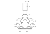
挟持部材33は、図2に示すように、一対の挟持片330からなる。各挟持片330は、駆動シリンダ34の先端に設けられた支持部35に回動可能に取り付けられ、ガラスパネル2と直交する方向(図2(a)にMで示す)に関して対称に配される。挟持片330は、支持部35に枢着された基部331と、基部331に固定されたツメ部332とを有する。ツメ部332は、摩擦係数が高く、且つ優れた強度を有する材料で形成することが好ましく、例えばウレタンで形成される。ツメ部332の先端部には第1平面部332aが形成されると共に、相手側のツメ部332と対向する面には第2平面部332bが形成される。第1平面部332aの外側(挟持部材33の対称中心Mから離隔する側)には切り欠き面332cが設けられ、第1平面部332aと切り欠き面332cとの間に鈍角な角部332dが形成される。図2(a)は、挟持部材33の先端部を最も開いた状態を示し、このとき、各挟持片330の第1平面部332aはガラスパネル2と平行な同一平面上に配される。図2(d)は、挟持部材33を閉じた状態を示し、このとき、各挟持片330の第2平面部332b同士が面接触する。
As shown in FIG. 2, the
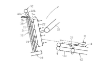
押さえ機構32は、例えば図1に示すように、ゴム等の弾性材料からなる押さえ部32aと、金属材料等の剛性体からなり、押さえ部32aを支持する押さえ支持部32bとを有する。押さえ機構32は、上下方向にスライド可能に設けられ、下端位置で、押さえ部32aにより合紙3の上端部を押さえるようになっている。
As shown in FIG. 1, for example, the
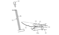
搬送装置40は、上下一対の無端状のベルト41・42と、各ベルトの内側に配された駆動ローラ43及び従動ローラ44とを有し、パネル移送装置20の下部に配される。一対のベルト41・42は平行に配され、その間に合紙3が引き込まれるようになっている。図示例では、一対のベルト41・42は、積層体12から離隔する方向へ向けて徐々に低くなるように傾斜して配されている。下側のベルト42は、積層体12側の一部を回動させることができ、この回動可能部42aを上側のベルト41から離隔する方向に回動させることにより、一対のベルト41、42の積層体12側が開口するようになっている(図1の点線参照)。各ベルト41、42の駆動ローラを駆動すると、ベルト41、42が回転し、ベルト41、42の間に挟まれた合紙3が後方(積層体12から離隔する方向)に搬送される。搬送装置40の後端まで達した合紙3は、図示しない排紙トレーに収容される。
The
ベルト41・42の一方又は双方には、ベルト間の隙間を調整する隙間調整機構が設けられる(図示省略)。この隙間調整機構は、例えば、上側のベルトの従動ローラ44を下側に付勢するスプリング等の付勢手段を設けることにより構成される。この付勢手段により、上側のベルト41を常時は下側のベルト42に押し付け、ベルト間の合紙が捩れたり折り重なったりしたら、上側のベルト41の従動ローラ44が上方に移動してベルト間の隙間が広げられ、これにより合紙3の搬送を滞らせることなく行うことができる。
One or both of the
以下、解荷装置1によるガラスパネル2の解荷の手順を、合紙3をガラスパネル2から分離する工程を中心に、図2及び図3に基づいて説明する。尚、以下の説明において、積層体12の表側から順にガラスパネル2a・2b・2cと称し、ガラスパネル2aと2bとの間の合紙を合紙3a、ガラスパネル2bと2cとの間の合紙を合紙3bと称す。
Hereinafter, the procedure for unloading the
まず、図3(a)に示すように、パレット10上に載置された積層体12の一番表側のガラスパネル2aをパネル移送装置20で次工程へ移送する。具体的には、パネル移送装置20の各吸着部21をガラスパネル2aの表面に吸着固定した後、吸着部21をガラスパネル2aと直交する方向にスライドさせて、ガラスパネル2aを積層体12から離隔させる。このとき、上側の吸着部21を下側の吸着部21よりも若干早期にスライドさせることで、ガラスパネル2aと合紙3aとの間に空気が入り、ガラスパネル2aを積層体12から剥離しやすくなる。その後、アーム部23を動かしてガラスパネル2aを次工程に移送する。こうしてガラスパネル2aを積層体12から分離する際、合紙3の上端部を押さえ機構32の押さえ部32aで押さえているため、分離されるガラスパネル2aにつられて合紙3aが積層体12側のガラスパネル2bから剥離する事態を防止できる。尚、押さえ部32aは合紙3と共にガラスパネル2bの上端部を押さえているが、ガラスパネル2aの上端部は押さえていない。そのため、ガラスパネル2aの移送時に、押さえ部32aとガラスパネル2aとが干渉しないようになっている。これにより、ガラスパネル2aは押さえ部32aによって汚されることがない。
First, as shown in FIG. 3A, the
ガラスパネル2aをパネル移送装置20で移送している間に、図示しない第2駆動手段により挟持部材33をスライドさせて、積層体12に接近させる。これと共に、下側のベルト42の回動可能部42aを下方に回動させて、両ベルト41・42の先端部(積層体12側端部)を開く(図3(b)参照)。
While the
次に、合紙剥離機構31の第1駆動手段としての駆動シリンダ34を伸長し、挟持部材33をガラスパネル2と直交する方向にスライドさせて、各挟持片330の先端部をガラスパネル2に当接させる(図3(c)参照)。このとき、ツメ部332の第1平面部332aと合紙3aとが面接触する(図2(b)参照)。挟持部材33の先端部がガラスパネル2bの表面に付着した合紙3aに当接したら、駆動シリンダ34を停止させると共に、押さえ機構32を上昇させて合紙3aの押さえを解除する。そして、各挟持片330を回動して挟持部材33の先端部を閉じると共に、駆動シリンダ34を退入させて挟持部材33を合紙3aから離反する方向に後退させる。こうして、各挟持片330の先端部を合紙3aに当接させた状態を維持しながら挟持部材33を閉じることにより、合紙3aが各挟持片330の間に引き寄せられる(図2(c)参照)。挟持部材33が完全に閉じたら、各挟持片330の第2平面部332bの間に合紙3aが挟持される(図2(d)参照)。
Next, the driving
このように、挟持部材33を開いた状態で、各挟持片330の先端部を同時に合紙3aに当接させることで、挟持部材33で合紙3aを掴む領域(つかみ代、図2(b)にLで示す)を比較的大きく取る事ができるため、合紙3aを確実に掴むことができる。また、各挟持片330の第1平面部332aを合紙3aにぴったりと面接触させて接触面積を増やすことにより、両者の摩擦力を大きくすることができる。図2(b)に示す状態、すなわち挟持部材33を閉じ始めるときは、合紙3aとガラスパネル2bとの付着力が大きいため、上記のように挟持部材33と合紙3aとを面接触させて両者の摩擦力を大きくすることで、合紙3aをガラスパネル2bから確実に剥離することができる。合紙3aがガラスパネル2bに対して動き始めたら、各挟持片330の第2平面部332aと切り欠き面332cとの間の角部332dにより、合紙3aが折りたたまれるようにして引き寄せられる。
In this way, with the clamping
また、挟持部材33を後退させながら先端部を閉じることで、各挟持片330の先端部をガラスパネル2bに過度に強く押し付けることがないため、ガラスパネル2bを傷つける恐れを回避できる。特に、本実施形態では、挟持片330の第1平面部332aをガラスパネル2に当接させ、且つ、鈍角な角部332dで合紙3aを引き寄せるため、ガラスパネル2を傷つける恐れをより確実に回避できる。
Further, by closing the distal end portion while retracting the clamping
その後、挟持部材33で合紙3aを掴んだ状態で駆動シリンダ34を退入させ、挟持部材33をガラスパネル2bから離隔する方向にスライドさせる(図2(e)参照)。このとき、挟持部材33の第2平面部332b同士で合紙3aを挟持しているため、合紙3aを確実に保持してガラスパネル2bから剥離することができる。そして、第2駆動手段で挟持部材33をベルト41・42側にスライドさせ(図3(c)参照)、挟持部材33で掴んだ合紙3aの一部をベルト41・42間の開口部に配する(図3(d)参照)。その後、挟持部材33を開いて合紙3aを離し、第1移動手段で挟持部材33を後退させ、挟持部材33が合紙3aと干渉しない位置まで退避させる。この状態で、下側のベルト42の回動可能部42aを回動させて上側のベルト41との開口部を閉じ、両ベルトで合紙3aを挟持する。そして、駆動ローラ43を駆動して合紙3aを搬送し、図示しない排紙トレーに収容する。
Thereafter, the
以上により、1番目のガラスパネル2aの移送、及び1番目の合紙3aの分離が完了する。その後、上記と同様にして、2番目以降のガラスパネルの移送及び合紙の分離を行う。
Thus, the transfer of the
1 解荷装置
2 ガラスパネル
3 合紙
10 パレット
12 積層体
20 パネル移送装置
30 合紙分離装置
31 合紙剥離機構
32 押さえ機構(分離防止手段)
33 挟持部材
330 挟持片
332a 第1平面部
332b 第2平面部
34 駆動シリンダ(第1スライド機構)
40 搬送装置
41・42 ベルト
42a 回動可能部
DESCRIPTION OF
33 Clamping
40 Conveying
Claims (4)
回動可能な一対の挟持片からなり、先端部を開閉可能な挟持部材と、挟持部材を板材と直交する方向にスライドさせるスライド機構とを有し、挟持部材を開いた状態で各挟持片の先端部を板材の表面に付着した合紙に当接させ、挟持部材を板材から離反する方向にスライドさせながら挟持部材の先端部を閉じて合紙を掴むようにした合紙分離装置。 An interleaving paper separating device for separating interleaving paper from the surface of a board material packed with interleaving paper,
It has a pair of pivotable clamping pieces, and has a clamping member that can open and close the tip, and a slide mechanism that slides the clamping member in a direction perpendicular to the plate material. An interleaving paper separating apparatus in which a leading end is brought into contact with a slip sheet attached to a surface of a plate material, and the gripping sheet is gripped by closing the leading end portion of the sandwiching member while sliding the sandwiching member in a direction away from the plate material.
Priority Applications (1)
| Application Number | Priority Date | Filing Date | Title |
|---|---|---|---|
| JP2008273247A JP5212636B2 (en) | 2008-10-23 | 2008-10-23 | Slip paper separator |
Applications Claiming Priority (1)
| Application Number | Priority Date | Filing Date | Title |
|---|---|---|---|
| JP2008273247A JP5212636B2 (en) | 2008-10-23 | 2008-10-23 | Slip paper separator |
Publications (2)
| Publication Number | Publication Date |
|---|---|
| JP2010100397A true JP2010100397A (en) | 2010-05-06 |
| JP5212636B2 JP5212636B2 (en) | 2013-06-19 |
Family
ID=42291405
Family Applications (1)
| Application Number | Title | Priority Date | Filing Date |
|---|---|---|---|
| JP2008273247A Expired - Fee Related JP5212636B2 (en) | 2008-10-23 | 2008-10-23 | Slip paper separator |
Country Status (1)
| Country | Link |
|---|---|
| JP (1) | JP5212636B2 (en) |
Cited By (1)
| Publication number | Priority date | Publication date | Assignee | Title |
|---|---|---|---|---|
| EP2716584A1 (en) * | 2011-05-30 | 2014-04-09 | Kawasaki Jukogyo Kabushiki Kaisha | System for transferring plate-shaped member having slip sheet, and method for transferring same |
Citations (6)
| Publication number | Priority date | Publication date | Assignee | Title |
|---|---|---|---|---|
| JPH09142679A (en) * | 1995-11-22 | 1997-06-03 | Murata Mach Ltd | Protecting paper sheet removal device |
| JP2000351449A (en) * | 1999-06-11 | 2000-12-19 | Mishima Kosan Co Ltd | Glass substrate conveying device |
| JP2003012165A (en) * | 2001-07-04 | 2003-01-15 | Fuji Photo Film Co Ltd | Slip sheet removing mechanism for printing plate sheet conveying device |
| JP2006298507A (en) * | 2005-04-15 | 2006-11-02 | Tanabe Kogyo Kk | Transfer equipment for glass substrate and transferring method |
| JP2007106569A (en) * | 2005-10-14 | 2007-04-26 | Tateyama Machine Kk | Interleaf peeling-off device |
| JP2009126609A (en) * | 2007-11-20 | 2009-06-11 | Asahi Glass Co Ltd | Slip sheet removing device |
-
2008
- 2008-10-23 JP JP2008273247A patent/JP5212636B2/en not_active Expired - Fee Related
Patent Citations (6)
| Publication number | Priority date | Publication date | Assignee | Title |
|---|---|---|---|---|
| JPH09142679A (en) * | 1995-11-22 | 1997-06-03 | Murata Mach Ltd | Protecting paper sheet removal device |
| JP2000351449A (en) * | 1999-06-11 | 2000-12-19 | Mishima Kosan Co Ltd | Glass substrate conveying device |
| JP2003012165A (en) * | 2001-07-04 | 2003-01-15 | Fuji Photo Film Co Ltd | Slip sheet removing mechanism for printing plate sheet conveying device |
| JP2006298507A (en) * | 2005-04-15 | 2006-11-02 | Tanabe Kogyo Kk | Transfer equipment for glass substrate and transferring method |
| JP2007106569A (en) * | 2005-10-14 | 2007-04-26 | Tateyama Machine Kk | Interleaf peeling-off device |
| JP2009126609A (en) * | 2007-11-20 | 2009-06-11 | Asahi Glass Co Ltd | Slip sheet removing device |
Cited By (3)
| Publication number | Priority date | Publication date | Assignee | Title |
|---|---|---|---|---|
| EP2716584A1 (en) * | 2011-05-30 | 2014-04-09 | Kawasaki Jukogyo Kabushiki Kaisha | System for transferring plate-shaped member having slip sheet, and method for transferring same |
| EP2716584A4 (en) * | 2011-05-30 | 2015-04-22 | Kawasaki Heavy Ind Ltd | System for transferring plate-shaped member having slip sheet, and method for transferring same |
| US9242818B2 (en) | 2011-05-30 | 2016-01-26 | Kawasaki Jukogyo Kabushiki Kaisha | System for and method of transferring plate-shaped member with interleaving paper thereon |
Also Published As
| Publication number | Publication date |
|---|---|
| JP5212636B2 (en) | 2013-06-19 |
Similar Documents
| Publication | Publication Date | Title |
|---|---|---|
| TWI500558B (en) | Protection sheet supply device | |
| TWI336657B (en) | Single sheet joining method and apparatus using the same | |
| TWI690476B (en) | Film peeling device | |
| TWI541134B (en) | Sheet peeling apparatus and peeling method, and sheet bonding apparatus and sticking method | |
| KR101440414B1 (en) | Apparatus and method for the separating and transporting of substrate | |
| TW201014772A (en) | Baling device for glass substrate and baling method thereof | |
| JP5146903B2 (en) | Glass substrate packing equipment | |
| JP5212636B2 (en) | Slip paper separator | |
| KR101724093B1 (en) | double-sided tape laminating apparatus | |
| CN107636821B (en) | Sheet peeling device and peeling method | |
| JP4304673B2 (en) | Interleaf gripping device and conveying device | |
| JP2010076875A (en) | Film peeling device and film peeling method | |
| JP4490345B2 (en) | Protective sheet peeling device | |
| JP2005321582A (en) | Film pasting method and film pasting device | |
| JP2007223645A (en) | Sealing device for taped envelope | |
| JP4393272B2 (en) | Unpacking the plate stack | |
| JPH05116831A (en) | Sheet stacker | |
| JP2014024616A (en) | Interleaf taking-out method and device thereof | |
| JPH1135225A (en) | Method and device for peeling film | |
| JP6577813B2 (en) | Processing equipment | |
| JP7415395B2 (en) | Protective sheet peeling device and protective sheet peeling method | |
| JP4083140B2 (en) | Coated film removing apparatus for articles and method therefor | |
| JP4983214B2 (en) | Film peeling device | |
| JP4522481B2 (en) | Method and apparatus for unpacking plate stack | |
| JP2012017112A (en) | Sealing apparatus |
Legal Events
| Date | Code | Title | Description |
|---|---|---|---|
| A621 | Written request for application examination |
Free format text: JAPANESE INTERMEDIATE CODE: A621 Effective date: 20110607 |
|
| A977 | Report on retrieval |
Free format text: JAPANESE INTERMEDIATE CODE: A971007 Effective date: 20120905 |
|
| A131 | Notification of reasons for refusal |
Free format text: JAPANESE INTERMEDIATE CODE: A131 Effective date: 20120910 |
|
| A521 | Written amendment |
Free format text: JAPANESE INTERMEDIATE CODE: A523 Effective date: 20121025 |
|
| TRDD | Decision of grant or rejection written | ||
| A01 | Written decision to grant a patent or to grant a registration (utility model) |
Free format text: JAPANESE INTERMEDIATE CODE: A01 Effective date: 20130130 |
|
| A61 | First payment of annual fees (during grant procedure) |
Free format text: JAPANESE INTERMEDIATE CODE: A61 Effective date: 20130212 |
|
| R150 | Certificate of patent or registration of utility model |
Free format text: JAPANESE INTERMEDIATE CODE: R150 |
|
| FPAY | Renewal fee payment (event date is renewal date of database) |
Free format text: PAYMENT UNTIL: 20160308 Year of fee payment: 3 |
|
| LAPS | Cancellation because of no payment of annual fees |