JP2010099565A - Cleaning system - Google Patents
Cleaning system Download PDFInfo
- Publication number
- JP2010099565A JP2010099565A JP2008271797A JP2008271797A JP2010099565A JP 2010099565 A JP2010099565 A JP 2010099565A JP 2008271797 A JP2008271797 A JP 2008271797A JP 2008271797 A JP2008271797 A JP 2008271797A JP 2010099565 A JP2010099565 A JP 2010099565A
- Authority
- JP
- Japan
- Prior art keywords
- layer portion
- roller
- cleaning
- outer layer
- cleaned
- Prior art date
- Legal status (The legal status is an assumption and is not a legal conclusion. Google has not performed a legal analysis and makes no representation as to the accuracy of the status listed.)
- Granted
Links
- 238000004140 cleaning Methods 0.000 title claims abstract description 107
- 239000000463 material Substances 0.000 claims abstract description 82
- 230000005611 electricity Effects 0.000 claims abstract description 21
- 230000003068 static effect Effects 0.000 claims abstract description 21
- 239000000428 dust Substances 0.000 claims abstract description 13
- 230000002093 peripheral effect Effects 0.000 claims description 25
- JOYRKODLDBILNP-UHFFFAOYSA-N Ethyl urethane Chemical compound CCOC(N)=O JOYRKODLDBILNP-UHFFFAOYSA-N 0.000 claims description 16
- 239000011538 cleaning material Substances 0.000 claims description 14
- NIXOWILDQLNWCW-UHFFFAOYSA-N acrylic acid group Chemical group C(C=C)(=O)O NIXOWILDQLNWCW-UHFFFAOYSA-N 0.000 claims description 8
- 229910052731 fluorine Inorganic materials 0.000 claims description 7
- 239000011737 fluorine Substances 0.000 claims description 7
- YCKRFDGAMUMZLT-UHFFFAOYSA-N Fluorine atom Chemical compound [F] YCKRFDGAMUMZLT-UHFFFAOYSA-N 0.000 claims description 5
- 238000009413 insulation Methods 0.000 claims description 4
- 239000013013 elastic material Substances 0.000 claims description 3
- 239000000945 filler Substances 0.000 claims description 3
- 229910052751 metal Inorganic materials 0.000 abstract description 8
- 239000002184 metal Substances 0.000 abstract description 8
- 239000010410 layer Substances 0.000 description 116
- 238000012546 transfer Methods 0.000 description 17
- LFQSCWFLJHTTHZ-UHFFFAOYSA-N Ethanol Chemical compound CCO LFQSCWFLJHTTHZ-UHFFFAOYSA-N 0.000 description 11
- 238000012360 testing method Methods 0.000 description 11
- 239000000853 adhesive Substances 0.000 description 9
- 230000001070 adhesive effect Effects 0.000 description 9
- 229920002799 BoPET Polymers 0.000 description 8
- OKTJSMMVPCPJKN-UHFFFAOYSA-N Carbon Chemical compound [C] OKTJSMMVPCPJKN-UHFFFAOYSA-N 0.000 description 7
- 229910052799 carbon Inorganic materials 0.000 description 7
- 239000004020 conductor Substances 0.000 description 7
- 239000000126 substance Substances 0.000 description 7
- XLYOFNOQVPJJNP-UHFFFAOYSA-N water Substances O XLYOFNOQVPJJNP-UHFFFAOYSA-N 0.000 description 7
- 239000000654 additive Substances 0.000 description 5
- 230000000052 comparative effect Effects 0.000 description 5
- 229920001577 copolymer Polymers 0.000 description 5
- 229920000728 polyester Polymers 0.000 description 5
- 229920002803 thermoplastic polyurethane Polymers 0.000 description 5
- 229920000178 Acrylic resin Polymers 0.000 description 4
- 239000004925 Acrylic resin Substances 0.000 description 4
- PPBRXRYQALVLMV-UHFFFAOYSA-N Styrene Chemical compound C=CC1=CC=CC=C1 PPBRXRYQALVLMV-UHFFFAOYSA-N 0.000 description 4
- 230000005684 electric field Effects 0.000 description 4
- 238000011056 performance test Methods 0.000 description 4
- 229920002635 polyurethane Polymers 0.000 description 4
- 239000004814 polyurethane Substances 0.000 description 4
- 238000005406 washing Methods 0.000 description 4
- 239000004433 Thermoplastic polyurethane Substances 0.000 description 3
- 230000000996 additive effect Effects 0.000 description 3
- 229920000058 polyacrylate Polymers 0.000 description 3
- 239000011347 resin Substances 0.000 description 3
- 229920005989 resin Polymers 0.000 description 3
- 239000002356 single layer Substances 0.000 description 3
- 238000011144 upstream manufacturing Methods 0.000 description 3
- 239000004809 Teflon Substances 0.000 description 2
- 229920006362 Teflon® Polymers 0.000 description 2
- 230000000740 bleeding effect Effects 0.000 description 2
- 229920005549 butyl rubber Polymers 0.000 description 2
- 230000007423 decrease Effects 0.000 description 2
- 238000010586 diagram Methods 0.000 description 2
- 239000011521 glass Substances 0.000 description 2
- 238000005259 measurement Methods 0.000 description 2
- 229920000642 polymer Polymers 0.000 description 2
- 229910052710 silicon Inorganic materials 0.000 description 2
- 239000010703 silicon Substances 0.000 description 2
- 229920003002 synthetic resin Polymers 0.000 description 2
- 239000000057 synthetic resin Substances 0.000 description 2
- 239000002699 waste material Substances 0.000 description 2
- 125000000022 2-aminoethyl group Chemical group [H]C([*])([H])C([H])([H])N([H])[H] 0.000 description 1
- XUIMIQQOPSSXEZ-UHFFFAOYSA-N Silicon Chemical compound [Si] XUIMIQQOPSSXEZ-UHFFFAOYSA-N 0.000 description 1
- 239000004902 Softening Agent Substances 0.000 description 1
- GWEVSGVZZGPLCZ-UHFFFAOYSA-N Titan oxide Chemical compound O=[Ti]=O GWEVSGVZZGPLCZ-UHFFFAOYSA-N 0.000 description 1
- 229920006243 acrylic copolymer Polymers 0.000 description 1
- 239000012790 adhesive layer Substances 0.000 description 1
- 239000002216 antistatic agent Substances 0.000 description 1
- JRPBQTZRNDNNOP-UHFFFAOYSA-N barium titanate Chemical compound [Ba+2].[Ba+2].[O-][Ti]([O-])([O-])[O-] JRPBQTZRNDNNOP-UHFFFAOYSA-N 0.000 description 1
- 229910002113 barium titanate Inorganic materials 0.000 description 1
- 239000003575 carbonaceous material Substances 0.000 description 1
- 239000002131 composite material Substances 0.000 description 1
- 150000001875 compounds Chemical class 0.000 description 1
- 238000013461 design Methods 0.000 description 1
- 239000003989 dielectric material Substances 0.000 description 1
- 238000005516 engineering process Methods 0.000 description 1
- 239000004744 fabric Substances 0.000 description 1
- 239000010419 fine particle Substances 0.000 description 1
- 125000001153 fluoro group Chemical group F* 0.000 description 1
- 238000011086 high cleaning Methods 0.000 description 1
- 230000006698 induction Effects 0.000 description 1
- 150000002500 ions Chemical class 0.000 description 1
- 239000012948 isocyanate Substances 0.000 description 1
- IQPQWNKOIGAROB-UHFFFAOYSA-N isocyanate group Chemical group [N-]=C=O IQPQWNKOIGAROB-UHFFFAOYSA-N 0.000 description 1
- 150000002513 isocyanates Chemical class 0.000 description 1
- 238000012423 maintenance Methods 0.000 description 1
- 239000000203 mixture Substances 0.000 description 1
- 239000003921 oil Substances 0.000 description 1
- 239000000843 powder Substances 0.000 description 1
- 238000001179 sorption measurement Methods 0.000 description 1
- 239000000758 substrate Substances 0.000 description 1
- OGIDPMRJRNCKJF-UHFFFAOYSA-N titanium oxide Inorganic materials [Ti]=O OGIDPMRJRNCKJF-UHFFFAOYSA-N 0.000 description 1
- 238000004804 winding Methods 0.000 description 1
Images


Abstract
Description
本発明は、例えばフィルム、シートなどの薄い被クリーニング材の表面に付着する異物も除去することができるクリーニングシステムに関するものである。 The present invention relates to a cleaning system that can also remove foreign substances adhering to the surface of a thin material to be cleaned such as a film or sheet.
従来、フラットパネルディスプレイ(FPD)のガラス基板や、貼り合わせフィルムなどの薄い被クリーニング材の表面上に付着する塵埃などの異物を除去するクリーニングシステムとしては、粘着ローラを用い、それの粘着力を利用して前記異物を除去するようにしたものが知られている(例えば、特許文献1参照)。
このような粘着ローラでは、平均径1μm以下の異物を取り除くことができず、また粘着ローラの表面(粘着層)に一旦付着した塵埃などの異物を完全に除去するのが困難であり、メンテナンス性に劣る。また、被クリーニング材に粘着ローラをある程度圧力を加えて押し付け、異物を粘着除去するようにしているので、被クリーニング材が例えばフィルムであると、前記異物を除去するだけでなく、フィルムがローラ表面に張り付くおそれがある。 Such an adhesive roller cannot remove foreign matters having an average diameter of 1 μm or less, and it is difficult to completely remove foreign matters such as dust once adhering to the surface (adhesive layer) of the adhesive roller. Inferior to In addition, since the adhesive roller is pressed against the material to be cleaned to some extent to remove the foreign material, if the material to be cleaned is, for example, a film, the film is not only removed There is a risk of sticking to.
そこで、発明者は、電子写真技術を応用し、被クリーニング材から塵埃などの異物を除去する際に、接触帯電によりクリーニングローラの外周面に、前記異物を静電気により吸着する電荷を帯電させれば、前記被クリーニング材から前記クリーニングローラにより前記異物を除去することができることに着想し、本発明をなしたものである。 Therefore, the inventor applies electrophotographic technology and removes foreign matters such as dust from the material to be cleaned by charging the outer peripheral surface of the cleaning roller with static electricity by contact charging. The present invention has been made with the idea that the foreign matter can be removed from the material to be cleaned by the cleaning roller.
この発明は、メンテナンス性に優れ、フィルム、シートなどの薄い被クリーニング材上の異物(塵埃など)を除去するような場合でも、被クリーニング材がローラ表面に張り付くのを回避して前記異物を除去できるクリーニングシステムを提供することを目的とする。 This invention is excellent in maintainability, and even when removing foreign matters (dust etc.) on thin materials to be cleaned such as films and sheets, the foreign materials are removed by avoiding the material to be cleaned sticking to the roller surface. An object of the present invention is to provide a cleaning system that can be used.
請求項1の発明は、被クリーニング材の表面に接触しつつ回転しながら前記被クリーニング材に対し相対移動するクリーニングローラを備え、前記被クリーニング材の表面上に付着する塵埃などの異物を前記クリーニングローラによって静電気を利用して取り除くクリーニングシステムであって、前記クリーニングローラは、導電性を有する芯棒と、この芯棒の外側に設けられる円筒状の内層部と、その内層部の外側に設けられる円筒状の外層部とを備え、前記外層部は50°以上の硬度(JIS−A)を有しかつ前記内層部よりも高抵抗であり、前記クリーニングローラの外層部を形成する材料は、前記被クリーニング材の表面上に付着する異物を吸着する電荷を帯電し得るものであることを特徴とする。ここで、外層部の硬度を50°以上とするのは、50°未満であれば、被クリーニング材がフィルムなどの薄いものである場合には、それをクリーニングローラが巻き込むんでしまうおそれがあるからである。また、内層部および外層部を形成する材料は、金属を除く材料(例えば高分子材料)から選択される。前記外層部の硬度は60°以上がより好ましい。
The invention of
なお、 本明細書において、「高抵抗」とは、電気抵抗が高いことを意味する。また、前記外層部の硬度は、外層部を形成する材料で成形された厚さ2mmの平板を用いて測定されるものである。 In the present specification, “high resistance” means high electrical resistance. Further, the hardness of the outer layer portion is measured using a flat plate having a thickness of 2 mm formed from a material forming the outer layer portion.
このようにすれば、クリーニングローラの外層部が、内層部よりも高抵抗で、前記被クリーニング材の表面上に付着する異物を吸着し得る電荷を帯電し得る材料からなるので、ローラ表面(外層部)の誘電率を高めて、被クリーニング材に付着する異物を、前記ローラ表面に静電気を利用して吸着させ、被クリーニング材の表面から除去することができる。 In this way, the outer layer portion of the cleaning roller has a higher resistance than the inner layer portion, and is made of a material that can charge a charge that can adsorb foreign matter adhering to the surface of the material to be cleaned. And the foreign matter adhering to the material to be cleaned can be adsorbed to the roller surface by utilizing static electricity and removed from the surface of the material to be cleaned.
このように、ローラ表面に異物を静電気により吸着しているだけであるので、クリーニングローラの外周面を水やアルコールで拭くことにより残存異物を前記ローラ表面から容易に取り除くことができ、粘着ローラをクリーニングローラとして利用したクリーニングシステムに比べて、メンテナンス性が優れる。 In this way, since the foreign matter is merely adsorbed to the roller surface by static electricity, residual foreign matter can be easily removed from the roller surface by wiping the outer peripheral surface of the cleaning roller with water or alcohol. Compared with the cleaning system used as a cleaning roller, the maintainability is excellent.
しかも、前記クリーニングローラは外層部を50°以上の高硬度とし、ローラ表面硬度を高めているので、ローラ表面の粘着性を低下させることができる。よって、被クリーニング材がフィルム、シートなどの薄物であっても、薄物である被クリーニング材のローラへの巻き付きを防止して、被クリーニング材表面のクリーニングを実施することができる。 Moreover, since the cleaning roller has a high hardness of 50 ° or more in the outer layer portion and the roller surface hardness is increased, the adhesiveness of the roller surface can be reduced. Therefore, even if the material to be cleaned is a thin material such as a film or a sheet, the surface of the material to be cleaned can be cleaned by preventing the material to be cleaned from being wound around the roller.
さらに、従来の粘着ローラは低硬度にするために軟化剤、オイルなどを添加する必要があるため、粘着ローラ表面にそれら添加剤のブリードが生じるという問題があるが、前記クリーニングローラは外層部を50°以上の高硬度とし、低硬度にする必要がないので、前記粘着ローラに生じるブリードの問題を改善する上で有利である。 Furthermore, since the conventional adhesive roller requires the addition of a softening agent, oil, etc. in order to reduce the hardness, there is a problem that bleeding of these additives occurs on the surface of the adhesive roller. However, the cleaning roller has an outer layer portion. Since the hardness is 50 ° or higher and it is not necessary to reduce the hardness, it is advantageous in improving the problem of bleeding that occurs in the adhesive roller.
この場合、請求項2に記載のように、前記内層部は前記外層部よりも低硬度であることが望ましい。
In this case, as described in
このようにすれば、内層部を外層部よりも低硬度とすることができるので、外層部が50°以上の硬度を有していても、ローラ全体としての硬度を従来のローラと同様の低硬度に維持して、ニップ幅を確保することができ、また、異物を噛み込んで被クリーニング材が損傷するという事態の発生を回避することができる。 In this way, the inner layer portion can be made to have a lower hardness than the outer layer portion. Therefore, even if the outer layer portion has a hardness of 50 ° or more, the hardness of the entire roller is as low as that of the conventional roller. The hardness can be maintained to ensure the nip width, and the occurrence of a situation in which foreign matter is caught and the cleaning material is damaged can be avoided.
この場合、請求項3に記載のように、前記内層部は導電性を有する弾性材料で形成され、前記外層部はアクリル混合ウレタンあるいはフッ素混合ウレタンで形成されている構成とすればよい。
In this case, as described in
このようにすれば、誘電性の高いウレタンをローラ外周面に用いる場合において誘電極性を調整することができ、アクリル混合ウレタンであればマイナスに帯電しやすい異物が、フッ素混合ウレタンであればプラスに帯電しやすい異物が、被クリーニング材から除去されやすくなる。 In this way, the dielectric polarity can be adjusted when urethane with high dielectric properties is used on the outer peripheral surface of the roller. Foreign matter that is easily charged is easily removed from the material to be cleaned.
請求項4に記載のように、前記外層部を形成する材料には、誘電フィラーが混合されていることが望ましい。 According to a fourth aspect of the present invention, it is desirable that a dielectric filler is mixed in the material forming the outer layer portion.
このようにすれば、誘電フィラーが混合されていることで、ローラ表面の静電容量が高められ、クリーニングローラに対し相対移動する被クリーニング材との接触ないし摩擦帯電などによりローラ表面に必要とする電荷が保持されやすくなり、前記ローラ表面に異物を吸着させ、被クリーニング材上から除去する上で有利となる。 In this case, the dielectric filler is mixed, so that the electrostatic capacity of the roller surface is increased, and the roller surface is required due to contact with the cleaning material moving relative to the cleaning roller or frictional charging. Charges are easily held, which is advantageous for adsorbing foreign matter on the roller surface and removing it from the material to be cleaned.
請求項5に記載のように、前記クリーニングローラの芯棒に、ローラ外周面に前記異物を静電気により吸着する電荷を帯電させ得る電圧が印加されていることが望ましい。 According to a fifth aspect of the present invention, it is desirable that a voltage capable of charging a charge that attracts the foreign matter by static electricity to the outer peripheral surface of the roller is applied to the core of the cleaning roller.
このようにすれば、ローラ外周面に異物を吸着する電荷を帯電させる電圧が印加されていることで、ローラ表面に前記異物を吸着するのに必要とされる高い電位が保持されやすくなる。よって、前記ローラ表面に異物を静電気により吸着させ、被クリーニング材上から除去する上で有利となる。 In this way, since a voltage for charging a charge for attracting foreign matter is applied to the outer peripheral surface of the roller, a high potential required to attract the foreign matter to the roller surface is easily maintained. Therefore, it is advantageous in adhering foreign matter to the roller surface by static electricity and removing it from the material to be cleaned.
請求項6に記載のように、前記クリーニングローラは、前記内層部が導電性を有する一方、前記外層部が絶縁性を有し、前記被クリーニング材を挟んで、前記クリーニングローラとは反対側にガイドローラが配置され、前記ガイドローラは、導電性を有する芯棒と、前記芯棒の外側に導電性を有する内層部と、前記内層部の外側に絶縁性を有する外層部とを備え、前記ガイドローラの芯棒および前記クリーニングローラの芯棒に対し、前記両芯棒のいずれか一方が他方よりも電位が高くなるように電圧を印加することを特徴とする。 According to a sixth aspect of the present invention, in the cleaning roller, the inner layer portion is electrically conductive, while the outer layer portion is insulative, and the cleaning roller is disposed on the opposite side of the cleaning material. A guide roller is disposed, and the guide roller includes a conductive core rod, an inner layer portion having conductivity on the outside of the core rod, and an outer layer portion having insulation on the outer side of the inner layer portion, A voltage is applied to the core rod of the guide roller and the core rod of the cleaning roller such that one of the both core rods has a higher potential than the other.
このようにすれば、2本のローラが被クリーニング材を挟んで対向しており、被クリーニング材がクリーニングローラ及びガイドローラが接触する位置において電界強度が最も高くなる。そして、与えられた電界に応じて被クリーニング材上の帯電異物がクリーニングローラに吸着され、除去される。 In this way, the two rollers are opposed to each other with the material to be cleaned interposed therebetween, and the electric field strength is highest at the position where the material to be cleaned contacts the cleaning roller and the guide roller. Then, charged foreign matter on the material to be cleaned is attracted to the cleaning roller and removed in accordance with the applied electric field.
本発明は、クリーニングローラの外層部が、内層部よりも高抵抗で、前記被クリーニング材の表面上に付着する異物を静電気により吸着し得る電荷を帯電し得る材料からなるので、前記ローラ表面に、塵埃などの異物を静電気にて吸着させ、被クリーニング材の表面から除去することができる。 In the present invention, the outer layer portion of the cleaning roller has a higher resistance than the inner layer portion and is made of a material capable of charging a charge that can adsorb foreign matter adhering to the surface of the material to be cleaned by static electricity. In addition, foreign matters such as dust can be adsorbed by static electricity and removed from the surface of the material to be cleaned.
しかも、前記クリーニングローラは外層部を50°以上の高硬度とし、ローラ表面硬度を高めているので、ローラ表面の粘着性を低下させ、被クリーニング材がフィルム、シートなどの薄物であっても、薄物である被クリーニング材のローラへの巻き付きを防止し、クリーニングを実施することができる。 In addition, since the cleaning roller has a high hardness of 50 ° or more in the outer layer portion and the roller surface hardness is increased, the adhesiveness of the roller surface is lowered, and even if the material to be cleaned is a thin object such as a film or sheet, It is possible to prevent the thin material to be cleaned from being wound around the roller and perform cleaning.
以下、本発明の実施の形態を図面に沿って説明する。 Hereinafter, embodiments of the present invention will be described with reference to the drawings.
図1は本発明に係るクリーニングシステムの一例による、塵埃などの異物を静電気を利用して除去する原理の説明図である。 FIG. 1 is an explanatory diagram of the principle of removing foreign matters such as dust using static electricity according to an example of a cleaning system according to the present invention.
図1に示すように、クリーニングシステム1は、被クリーニング材Sの表面S1に接触しつつ回転しながら前記被クリーニング材に対し相対移動するクリーニングローラ11(帯電体)を備え、このクリーニングローラ11によって被クリーニング材Sの表面S1上に付着する塵埃などの異物T(導体あるいは誘電体)を静電気を利用して取り除くものである。このクリーニングシステム1においては、具体的には図示していないが、クリーニングローラ11が配置されている部位までは、クリーニング前の被クリーニング材Sが第1の搬送手段(図示せず)によって搬入され、クリーニング後の被クリーニング材Sが第2の搬送手段(図示せず)によって搬出されるようになっている。なお、このように被クリーニング材Sが搬送される場合だけでなく、逆に、静止状態に支持されている被クリーニング材Sに対しクリーニングローラ11が移動して、表面S1がクリーニングされるようにすることもできるのはもちろんである。
As shown in FIG. 1, the
クリーニングローラ11は、導電性を有する芯金11a(芯棒)と、芯金11aの外側に設けられる円筒状の内層部11bと、その内層部11bの外側に設けられ内層部11bよりも高抵抗の材料からなる薄い円筒状の外層部11c(例えば、厚さ30μm程度)とを備え、二層構造となっている。ここで、外層部11cの厚さとしては、2〜500μm(より好ましくは、5〜50μm)が好ましい。これは、外層部11cの厚さが2μm未満ではローラ表面(外層部表面)に電荷が帯電しにくい傾向にある一方、500μmを超える厚さにするのは工業的に効率的でないからである。なお、芯金11aに代えて、導電性を有するカーボン材や合成樹脂複合材等からなる芯棒を用いることもできる。芯棒の体積抵抗としては、107Ωcm以下が望ましい。
The
内層部11bに用いている材料は、外層部11cよりも低硬度あるいは略同一の硬度とされる。内層部11bに用いている材料の電気特性としては、外層部11cよりも低抵抗であれば特に限定されるものではなく、誘電性を有するものであっても導電性を有するものであってもかまわないが、表面抵抗が1010〜1012Ω/□程度であることが好ましい。ただし、芯棒11aよりは高抵抗であることが好ましい。具体的には、導電性を有する弾性材料である、例えばカーボン(導電材)を含むポリエステル系ウレタン等を内部層11bに用いることができる。 The material used for the inner layer portion 11b has a lower hardness or substantially the same hardness as the outer layer portion 11c. The electrical characteristics of the material used for the inner layer portion 11b are not particularly limited as long as the resistance is lower than that of the outer layer portion 11c, and it may be dielectric or conductive. The surface resistance is preferably about 10 10 to 10 12 Ω / □. However, the resistance is preferably higher than that of the core rod 11a. Specifically, for example, polyester urethane containing carbon (conductive material), which is an elastic material having conductivity, can be used for the inner layer 11b.
外層部11cに用いている材料は、50°以上(望ましくは50°以上100°以下、より望ましくは55°以上100°以下、さらに望ましくは65°以上100°以下)の硬度を有する。また、外層部11cは内層部11bよりも高抵抗である。外層部11cは望ましくは108Ω/□以上の表面抵抗、より望ましくは1010Ω/□以上の表面抵抗、さらに望ましくは1011Ω/□以上の表面抵抗を有し、絶縁性を有する。 The material used for the outer layer portion 11c has a hardness of 50 ° or more (desirably 50 ° or more and 100 ° or less, more desirably 55 ° or more and 100 ° or less, and further desirably 65 ° or more and 100 ° or less). The outer layer portion 11c has a higher resistance than the inner layer portion 11b. The outer layer portion 11c preferably has a surface resistance of 10 8 Ω / □ or more, more preferably a surface resistance of 10 10 Ω / □ or more, and even more preferably a surface resistance of 10 11 Ω / □ or more.
このようなクリーニングローラ11の外層部11bを形成する材料は、被クリーニング材Sの表面S1上に付着する塵埃などの異物Tを静電気により吸着する電荷を帯電し得るものが選択される。つまり、異物Tに帯電される電荷に対し電位差が生じるようなものであればよく、異物Tに対して、帯電序列がプラス側あるいはマイナス側になるものが選択される。
As the material forming the outer layer portion 11b of the cleaning
なお、被クリーニング材S上に付着している異物に、どのような電荷が帯電するかは、通常、被クリーニング材の種類によっても変わり得るが、被クリーニング材の種類に応じて、外層部11bに用いる材料を選択することができる。 In addition, although what kind of electric charge is charged to the foreign matter adhering to the cleaning material S can usually vary depending on the type of the cleaning material, the outer layer portion 11b depends on the type of the cleaning material. The material used for can be selected.
本発明におけるクリーニングローラ11の外層部11cを形成する材料の好ましい例としては、ウレタン樹脂が挙げられ、さらにはアクリル混合ウレタンあるいはフッ素混合ウレタンが挙げられる。ここで、「アクリル混合ウレタン」とは、アクリル樹脂(例えば、メタクリル酸ーメタクリル酸メチル共重合体からなる主鎖にアミノエチル基がグラフトされてなるグラフト化合物)とウレタン樹脂(例えば、ポリエステルポリウレタンまたはポリエーテルポリウレタン)との混合物からなるものであり、「フッ素混合ウレタン」とは、ポリウレタンを主成分とし、フッ素基(例えば、炭素を主体とする重合体に担持され、ポリウレタンと共重合体を構成するもの、炭素を主体とする重合体に担持され、かつイソシアネート基(例えば、多官能のブロックイソシアネート)を含有する共重合体)を有する合成樹脂である。
Preferable examples of the material forming the outer layer portion 11c of the cleaning
前記したクリーニングローラ11によれば、クリーニングローラ11が、クリーニングの対象とする被クリーニング材Sに付着する異物Tに接触することで、静電誘導により異物Tにクリーニングローラ11の外周面とは異なる電荷が帯電され、塵埃などの異物との間に引力が発生し、前記異物が外層部11bの表面に静電気により吸着され、被クリーニング材の表面から異物が除去される。
According to the cleaning
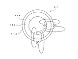
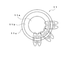
また、外層部11cおよび内層部11bをともに誘電体とする場合には、図2に示すように、外層部11cにおける表面電荷密度は比較的小となり、外層部11cを誘電体、内層部11bを導電体とする場合には、図3に示すように、外層部11cにおける表面電荷密度は比較的大となる。 Further, when both the outer layer portion 11c and the inner layer portion 11b are made of a dielectric, as shown in FIG. 2, the surface charge density in the outer layer portion 11c becomes relatively small, the outer layer portion 11c is made a dielectric, and the inner layer portion 11b is made a dielectric. In the case of a conductor, as shown in FIG. 3, the surface charge density in the outer layer portion 11c is relatively large.
続いて、クリーニングローラの性能についての試験結果について説明する。ここで、実施例1〜9は内層部がカーボン(導電材)を40vol%含むポリエステル系ウレタンで構成され、実施例10,11は内層部がカーボンを含まないポリエステル系ウレタンで構成される。実施例1〜11は外層部が熱可塑性ポリウレタンで構成され、実施例2〜実施例11はそれぞれ外層部が表1,2に記載の添加剤を含む。実施例13は内層部がブチルゴム外層部が熱可塑性ポリウレタンで構成されるものであり、実施例14は外層部が導電材を含まないものである。ただし、「フッ素」はウレタン・フッ素共重合体を、「アクリル」はアミノエチル化アクリルポリマーを、シリコンアクリルはシリコン・アクリル共重合体樹脂を意味する。尚、実施例3の外層部は、熱可塑性ポリウレタンとアクリル樹脂(アミノエチル化アクリルポリマー)とを60:40の割合で混合したものである。 Next, test results regarding the performance of the cleaning roller will be described. Here, in Examples 1 to 9, the inner layer portion is composed of polyester-based urethane containing 40 vol% of carbon (conductive material), and in Examples 10 and 11, the inner layer portion is composed of polyester-based urethane not containing carbon. In Examples 1 to 11, the outer layer portion is made of thermoplastic polyurethane, and in Examples 2 to 11, the outer layer portion includes the additives described in Tables 1 and 2, respectively. In Example 13, the inner layer portion is made of butyl rubber and the outer layer portion is made of thermoplastic polyurethane, and in Example 14, the outer layer portion does not contain a conductive material. However, “fluorine” means a urethane / fluorine copolymer, “acryl” means an aminoethylated acrylic polymer, and silicon acrylic means a silicon / acrylic copolymer resin. The outer layer portion of Example 3 is a mixture of thermoplastic polyurethane and acrylic resin (aminoethylated acrylic polymer) in a ratio of 60:40.
比較例1は外層部がないもので便宜的に内層部として記載したカーボンを含むポリエステル系ウレタンのみの単層構造のローラであり、比較例2は同様にブチルゴムのみの単層構造のローラ、比較例3は外層部導電材として、カーボン40phrおよびイオン導電性の機能性帯電防止剤(例えば三光化学工業株式会社製サンコノールMEK−10R)1phrを添加したものである。比較例4〜6は外層部がないもので硬度を変化させたものである。なお、前記実施例および前記比較例のローラの寸法としては、全て外径40mmφ、芯金を除いた部分の長さを250mmとした。
(ローラ硬度ー粘着性試験)
PICMAタックテスター(株式会社東洋精機製作所製)を用いて、PETフィルムに対する付着力を測定した。ここで、テスト条件は、幅15mm、加圧力500g、圧着時間10s、引き剥がし速度100cm/minとした。ここで、各硬度はJIS−A硬度で、内層硬度および外層硬度は厚さ2mmのシートを作製して、ローラ硬度は所定構造のローラを作製して、それぞれ測定した。
Comparative Example 1 has no outer layer portion, and is a roller having a single layer structure made only of polyester-based urethane containing carbon, which is conveniently described as the inner layer portion, and Comparative Example 2 is also a roller having a single layer structure only made of butyl rubber. In Example 3, 40 phr of carbon and 1 phr of an ion conductive functional antistatic agent (for example, Sanconol MEK-10R manufactured by Sanko Chemical Co., Ltd.) were added as the outer layer conductive material. In Comparative Examples 4 to 6, there is no outer layer portion, and the hardness is changed. In addition, as a dimension of the roller of the said Example and the said comparative example, all the outer diameters were 40 mm diameter, and the length of the part except a metal core was 250 mm.
(Roller hardness-adhesion test)
The adhesion to the PET film was measured using a PICMA tack tester (manufactured by Toyo Seiki Seisakusho Co., Ltd.). Here, the test conditions were a width of 15 mm, a pressing force of 500 g, a pressure bonding time of 10 s, and a peeling speed of 100 cm / min. Here, each hardness was JIS-A hardness, inner layer hardness and outer layer hardness were 2 mm thick sheets, and roller hardness was measured with a roller having a predetermined structure.
この表1に示す結果より、内層部硬度よりも外層部硬度を高硬度とし、ローラ全体としてのローラ硬度は低硬度(つまり内層硬度と同程度)に維持したまま、ローラの表面硬度(外層部硬度)を高めることで、ローラ表面の付着力(タック力)が低下することが分かる。
(ウエス拭き取り洗浄試験)
水あるいはアルコール(エタノール)を含ませた布ウエスを、異物が付着したローラ表面に対し一往復させ、水あるいはアルコール(エタノール)で拭いた、水洗浄後、アルコール洗浄後の残留異物を比較した。
From the results shown in Table 1, the outer layer hardness is higher than the inner layer hardness, and the roller hardness of the entire roller is maintained at a low hardness (that is, approximately the same as the inner layer hardness). It can be seen that by increasing the (hardness), the adhesion force (tack force) on the roller surface decreases.
(Waste wipe cleaning test)
A cloth waste containing water or alcohol (ethanol) was reciprocated once against the roller surface to which foreign matter had adhered, and was wiped with water or alcohol (ethanol). After washing with water, residual foreign matter after alcohol washing was compared.
この表2に示す結果より、実施例1〜9および13については、水やアルコールでローラ表面を拭いて洗浄した場合に、水の場合でもアルコールの場合でも、異物が確実に除去されることが分かる。よって、水洗浄後もアルコール洗浄後も、残留異物がなく、メンテナンス性に優れる。これは、ローラ表面の付着力が、粘着力ではなく、静電気的な吸着力であることから、簡単に除去できるものと考えられる。
(フィルム張り付き試験)
平板上に静電したPETフィルム(厚さ100μm,50μm)の上を、ローラに1kgの荷重をかけて転がし、フィルムの巻き付きの有無を調べた。
From the results shown in Table 2, in Examples 1 to 9 and 13, when the roller surface is wiped and washed with water or alcohol, foreign matter can be reliably removed in both cases of water and alcohol. I understand. Therefore, there is no residual foreign matter after water washing and alcohol washing, and the maintenance is excellent. This can be easily removed because the adhesion force on the roller surface is not an adhesive force but an electrostatic adsorption force.
(Film sticking test)
The film was rolled on a PET film (thickness 100 μm, 50 μm) electrostatically applied on a flat plate by applying a load of 1 kg to the roller, and the presence or absence of winding of the film was examined.
この表3に示す結果より、表面硬度が小さくなると(表2参照)、フィルムの、ローラへの巻き付きがあることが分かる。
(異物除去性能試験1−ローラ表面電位測定試験)
PETフィルム上に異物(平均径10μm、1μm、0.5μmの微粒子)を散布し、1kgの荷重をかけたローラを転がし、異物除去試験を行った。また、このときのローラ外周面の表面電位を測定した。
From the results shown in Table 3, it can be seen that when the surface hardness decreases (see Table 2), the film is wound around the roller.
(Foreign substance removal performance test 1-roller surface potential measurement test)
A foreign matter (fine particles having an average diameter of 10 μm, 1 μm, and 0.5 μm) was sprayed on the PET film, and a roller with a load of 1 kg was rolled to perform a foreign matter removal test. Further, the surface potential of the roller outer peripheral surface at this time was measured.
この表4の結果より、外層部の抵抗値が変化すると、異物除去性能が変化することが分かる。つまり、内層部の抵抗値に対して外層部の抵抗値が小さいと、径が0.5μm、1μmの異物の除去ができず、径が10μmの異物の除去が困難になる。 From the results in Table 4, it can be seen that the foreign matter removal performance changes when the resistance value of the outer layer portion changes. That is, if the resistance value of the outer layer portion is smaller than the resistance value of the inner layer portion, foreign matters having diameters of 0.5 μm and 1 μm cannot be removed, and it is difficult to remove foreign matters having a diameter of 10 μm.
高誘電率の添加剤(例えばチタン酸バリウムεs=1200、酸化チタンεs=83〜183など)を混合することにより(表1,2参照)、外層部の誘電性が高められる。
(イオン化ポテンシャルーローラ表面電位測定試験)
光電子分光装置AC-1(理研計器株式会社)を用いて、ローラ外周面のイオン化ポテンシャルを測定した。また、1kgの荷重をかけたローラをPETフィルム上に転がしたときのローラ外周面の表面電位を測定した。ここで、フッ素はウレタン・フッ素共重合体を、アクリルはアミノエチル化アクリルポリマーである。
By mixing a high dielectric constant additive (for example, barium titanate ε s = 1200, titanium oxide ε s = 83 to 183, etc.) (see Tables 1 and 2), the dielectric property of the outer layer portion is enhanced.
(Ionization potential roller surface potential measurement test)
The ionization potential of the roller outer peripheral surface was measured using a photoelectron spectrometer AC-1 (Riken Keiki Co., Ltd.). Further, the surface potential of the roller outer peripheral surface when a roller loaded with 1 kg was rolled onto a PET film was measured. Here, fluorine is a urethane / fluorine copolymer, and acrylic is an aminoethylated acrylic polymer.
この表5の結果より、ローラ外周面の帯電性を、添加剤の添加により制御できることが分かる。
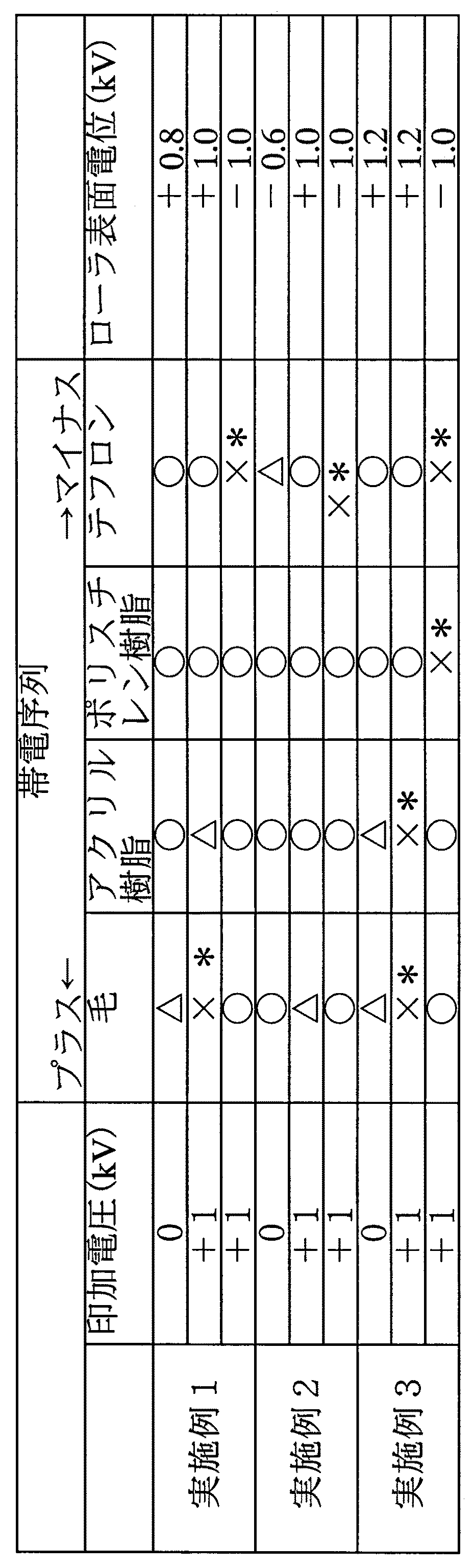
(異物除去性能試験2)
PETフィルム上に異物としての毛(人間の髪の毛:長さ300μm)、アクリル樹脂(100μm大)、スチレン樹脂(100μm大)、テフロン(100μm大)を散布し、1kgの荷重をかけたローラを転がし、異物除去試験を行った。
From the results in Table 5, it can be seen that the charging property of the roller outer peripheral surface can be controlled by the addition of an additive.
(Foreign substance removal performance test 2)
Sprinkle hair as a foreign object (human hair: 300 μm long), acrylic resin (100 μm large), styrene resin (100 μm large), Teflon (100 μm large) on a PET film and roll a roller with a load of 1 kg. A foreign matter removal test was conducted.
物質の帯電極性により電位差が生じやすい物質と生じにくい物資が存在し、クリーニング性が異なることが分かる。
(異物除去性能試験3)
PETフィルム上に異物としての毛(人間の髪の毛:300μm)、アクリル樹脂(100μm大)、スチレン樹脂(100μm大)、テフロン(100μm大)を散布し、1kgの荷重をかけたローラを転がし、異物除去試験を行った。ただし、このとき、ローラ芯金に外部電源を用い、+1kV、−1kVの電圧を印加しつつ行った。また、ローラ帯電性を測定した。結果を前記異物除去性能試験2の結果と対比して、次の表7に示す。
It can be seen that there are substances that tend to cause a potential difference depending on the charge polarity of the substance, and materials that are difficult to generate, and the cleaning properties are different.
(Foreign substance removal performance test 3)
Sprinkle hair (human hair: 300 μm), acrylic resin (100 μm size), styrene resin (100 μm size), Teflon (100 μm size) as a foreign material on a PET film, roll a roller under a 1 kg load, A removal test was performed. However, at this time, an external power source was used for the roller metal core, and a voltage of +1 kV and −1 kV was applied. Also, the roller chargeability was measured. The results are shown in the following Table 7 in comparison with the results of the foreign matter
外部からの電圧の印加を行うことにより、異物との間に安定した電位差を生じ、高いクリーニング性を有するシステム設計が可能となる。 By applying a voltage from the outside, a stable potential difference is generated between the foreign matter and a system design having a high cleaning property becomes possible.
また、外部からの印加する電圧の符号が摩擦帯電により生じる符号と逆極性である場合に、吸着した異物を放出できることが分かる(表7の*参照)。
(損傷試験)
PETフィルム上にガラス粉を散布し、5kgの荷重をかけたローラを転がし、PETフィルムについた傷を確認した。
It can also be seen that the adsorbed foreign matter can be released when the sign of the voltage applied from the outside is opposite in polarity to the sign generated by frictional charging (see * in Table 7).
(Damage test)
Glass powder was sprayed on the PET film, and a roller with a 5 kg load was rolled to check the scratches on the PET film.
表8より、比較例4〜6のウレタン単層のローラにおいて硬度を高くすると傷が生じるが、実施例1では、低硬度の内層部の外側にそれよりも高硬度の外層部を設けていても、ローラ全体としては低硬度を維持することができ、傷の発生を防止できることが分かる。 From Table 8, scratches occur when the hardness of the urethane single layer rollers of Comparative Examples 4 to 6 is increased, but in Example 1, an outer layer portion having higher hardness is provided outside the inner layer portion having low hardness. However, it can be seen that the entire roller can maintain a low hardness and can prevent the occurrence of scratches.
前記実施の形態では、クリーニングローラ11を被クリーニング材Sの表面S1に接触させ、表面S1側をクリーニングするようにしているだけであるが、裏面S2側だけのクリーニングするようにしてもよいし、また表面S1側だけのクリーニングだけでよい場合には、図4に示すように、被クリーニング材Sを挟んで、クリーニングローラ11とは反対側にガイドローラ21を配置することも可能である。この場合、ガイドローラ21は、芯金21aと、この芯金21aの外側に導電性を有する内層部21bと、この内層部21bの外側に絶縁性を有する外層部21cとを備える。ガイドローラ21の芯金21a、内層部21bおよび外層部21cは、例えばクリーニングローラの芯金11a、内層部11bおよび外層部11cと実質的に同一の材料を用いてそれぞれ形成することができ、内外層部ガイドローラ21の芯金21aの電位が、クリーニングローラ11の芯金11aの電位より低くなるように、あるいはその逆になるように、各芯金21a,11aに電圧が印加されている。
In the above embodiment, the cleaning
この場合には、2本のローラ11,21が被クリーニング材Sを挟んで対向しており、被クリーニング材Sがクリーニングローラ11及びガイドローラ21が接触する位置において電界強度が最も高くなり、与えられた電界に応じて被クリーニング材S上の帯電異物がクリーニングローラ11の外周面に静電気により吸着され、被クリーニング材S上から効果的に除去される。
In this case, the two
また、図5に示すように、クリーニングローラ11の、被クリーニング材Sとは反対側に転写ローラ31を設け、クリーニングローラ11に付着した異物を、転写ローラ31に転写させるようにすることも可能である。なお、転写ローラ31は、芯金41aと、この芯金41aの外側に導電性を有する内層部41bと、この内層部41bの外側に絶縁性を有する外層部41cとを備える。この転写ローラ31の芯金31a、内層部31bおよび外層部31cも、例えば、クリーニングローラの芯金11a、内層部11bおよび外層部11cと実質的に同一の材料を用いてそれぞれ形成することができ、外層部31cへの添加剤の添加などにより、外層部31cの外周面が、クリーニングローラ11の外周面に付着する異物を静電気により吸着する電荷を帯電し得るようになっている。つまり、転写ローラ31の外周面と、クリーニングローラ11の外周面との間には、クリーニングローラ11の外周面に付着している異物を転写ローラ31の外周面に転写(移動)させ得る程度の電位差が生じるようになっている。よって、クリーニングローラ11の外周面に付着する異物が、クリーニングローラ11の回転により転写ローラ31付近に到達すると、クリーニングローラ11から転写ローラ31に転写(移動)することになり、クリーニングローラ11の外周面から異物が除去され、クリーニングローラ11は外周面に異物を吸着していないことが維持されることになる。
In addition, as shown in FIG. 5, a
この場合、図5において鎖線で示すように、被クリーニング材Sの裏面S2側に、表面S1側のクリーニングローラ11や転写ローラ31に対応して、裏面S2側をクリーニングするためのクリーニングローラ11や転写ローラ31を設け、被クリーニング材Sの表裏面S1,S2を同時にクリーニングすることも可能である。尚、裏面側にクリーニングローラ11や転写ローラ31を設けない場合には、前述したガイドローラを設けるようにすることも可能である。
In this case, as indicated by a chain line in FIG. 5, the cleaning
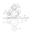
図5に示すクリーニングシステムは、具体的には、例えば図6に、クリーニングローラと転写ローラとを有する場合の一例を示す構造とすることができる。つまり、クリーニングローラ11と転写ローラ21とによって構成されるクリーニング部Wの上流側に、複数本の丸ベルト25a、駆動ローラ25bおよび従動ローラ25cによってクリーニング前の被クリーニング材S(例えば帯状のフィルム)を搬送する上流側ベルトコンベヤ25が配置され、下流側に、複数本の丸ベルト26a、駆動ローラ26bおよび従動ローラ26cによってクリーニング後の被クリーニング材Sを搬送する下流側ベルトコンベヤ26が配置されている。なお、丸ベルト26aを用いるのは、被クリーニング材Sとの接触部分を少なくして、異物の付着を回避するためである。クリーニング部Wおよびコンベヤ25,26の駆動系の具体的な構成は図示を省略している。
Specifically, the cleaning system shown in FIG. 5 may have a structure shown in FIG. 6 as an example in the case of having a cleaning roller and a transfer roller. That is, on the upstream side of the cleaning portion W constituted by the cleaning
さらに、図7に示すように、クリーニングローラ11の上流側には、帯電ローラ41を設け、異物Tに帯電される電荷に対して一定の電位差を有する電荷(つまり、異物を静電気により吸着し得る電荷)を、クリーニングローラ11の外周面(外層部)に予め帯電させ、クリーニングローラ11の外周面が所定の電荷を帯電するのをアシストするように構成することも可能である。なお、帯電ローラ41は、電圧が印加される芯金41aと、この芯金41aの外側に導電性を有する内層部41bと、この内層部41bの外側に絶縁性を有する外層部41cとを備える。この帯電ローラ41の芯金41a、内層部41bおよび外層部41cも、例えばクリーニングローラの芯金11a、内層部11bおよび外層部11cと実質的に同一の材料を用いてそれぞれ形成することができ、芯金11aに所定の電圧を印加することで、外層部41cの外周面にクリーニングローラ11の外周面を接触させることで、クリーニングローラ11の外周面に対し、異物を静電気により吸着し得る電荷を帯電させるようになっている。この場合も、被クリーニング材Sの裏面S2側に、表面S1側のクリーニングローラ11、転写ローラ31および帯電ローラ41に対応して、裏面S2側をクリーニングするためのクリーニングローラ11、転写ローラ31および帯電ローラ41を設け、被クリーニング材Sの表裏面S1,S2を同時にクリーニングすることも可能であるし、前述したガイドローラを設けるようにすることも可能である。
Further, as shown in FIG. 7, a charging
S 被クリーニング材
T 異物
1 クリーニングシステム
11 クリーニングローラ
11a 芯金
11b 内層部
11c 外層部
21 ガイドローラ
21a 芯金
21b 内層部
21c 外層部
S Cleaning Material
Claims (6)
前記クリーニングローラは、導電性を有する芯棒と、この芯棒の外側に設けられる円筒状の内層部と、その内層部の外側に設けられる円筒状の外層部とを備え、前記外層部は50°以上の硬度(JIS−A)を有しかつ前記内層部よりも高抵抗であり、
前記クリーニングローラの外層部を形成する材料は、前記被クリーニング材の表面上に付着する異物を静電気により吸着する電荷を帯電し得るものであることを特徴とするクリーニングシステム。
A cleaning roller that moves relative to the material to be cleaned while rotating while contacting the surface of the material to be cleaned is provided, and foreign matter such as dust adhering to the surface of the material to be cleaned is electrostatically utilized by the cleaning roller. A cleaning system to remove,
The cleaning roller includes a conductive core rod, a cylindrical inner layer portion provided outside the core rod, and a cylindrical outer layer portion provided outside the inner layer portion, and the outer layer portion includes 50 Having a hardness of more than ° (JIS-A) and higher resistance than the inner layer part,
The cleaning system is characterized in that the material forming the outer layer portion of the cleaning roller is capable of charging a charge that adsorbs foreign matter adhering to the surface of the cleaning material by static electricity.
The cleaning system according to claim 1, wherein the inner layer portion has a lower hardness than the outer layer portion.
The cleaning system according to claim 1 or 2, wherein the inner layer portion is formed of an elastic material having conductivity, and the outer layer portion is formed of acrylic mixed urethane or fluorine mixed urethane.
The cleaning system according to claim 1, wherein a dielectric filler is mixed in the material forming the outer layer portion.
5. The cleaning system according to claim 1, wherein a voltage capable of charging the outer peripheral surface of the cleaning roller with a charge that adsorbs the foreign matter due to static electricity is applied to the core of the cleaning roller.
前記被クリーニング材を挟んで、前記クリーニングローラとは反対側にガイドローラが配置され、
前記ガイドローラは、導電性を有する芯棒と、前記芯棒の外側に導電性を有する内層部と、前記内層部の外側に絶縁性を有する外層部とを備え、
前記ガイドローラの芯棒および前記クリーニングローラの芯棒に対し、前記両芯棒のいずれか一方が他方よりも電位が高くなるように電圧を印加することを特徴とする請求項1〜4のいずれかに記載のクリーニングシステム。 In the cleaning roller, the inner layer portion has conductivity, while the outer layer portion has insulation.
A guide roller is disposed on the opposite side of the cleaning roller across the material to be cleaned,
The guide roller includes a core rod having conductivity, an inner layer portion having conductivity on the outside of the core rod, and an outer layer portion having insulation on the outside of the inner layer portion,
The voltage is applied to the core rod of the guide roller and the core rod of the cleaning roller so that one of the both core rods has a higher potential than the other. A cleaning system according to the above.
Priority Applications (1)
| Application Number | Priority Date | Filing Date | Title |
|---|---|---|---|
| JP2008271797A JP5491017B2 (en) | 2008-10-22 | 2008-10-22 | Cleaning system |
Applications Claiming Priority (1)
| Application Number | Priority Date | Filing Date | Title |
|---|---|---|---|
| JP2008271797A JP5491017B2 (en) | 2008-10-22 | 2008-10-22 | Cleaning system |
Publications (3)
| Publication Number | Publication Date |
|---|---|
| JP2010099565A true JP2010099565A (en) | 2010-05-06 |
| JP2010099565A5 JP2010099565A5 (en) | 2011-08-18 |
| JP5491017B2 JP5491017B2 (en) | 2014-05-14 |
Family
ID=42290685
Family Applications (1)
| Application Number | Title | Priority Date | Filing Date |
|---|---|---|---|
| JP2008271797A Active JP5491017B2 (en) | 2008-10-22 | 2008-10-22 | Cleaning system |
Country Status (1)
| Country | Link |
|---|---|
| JP (1) | JP5491017B2 (en) |
Cited By (10)
| Publication number | Priority date | Publication date | Assignee | Title |
|---|---|---|---|---|
| WO2011158504A1 (en) * | 2010-06-17 | 2011-12-22 | バンドー化学株式会社 | Cleaning system |
| WO2012111302A1 (en) * | 2011-02-15 | 2012-08-23 | バンドー化学株式会社 | Cleaning device |
| JP2012210778A (en) * | 2011-03-31 | 2012-11-01 | Du Pont-Toray Co Ltd | Method of manufacturing polyimide film |
| JP2014025985A (en) * | 2012-07-24 | 2014-02-06 | Fuji Xerox Co Ltd | Powder particle recovering device and image forming apparatus |
| JP2014073444A (en) * | 2012-10-03 | 2014-04-24 | Bando Chem Ind Ltd | Cleaning tool and cleaning device |
| KR20150013303A (en) | 2012-06-06 | 2015-02-04 | 반도 카가쿠 가부시키가이샤 | Cleaning device |
| JP2015044094A (en) * | 2011-12-02 | 2015-03-12 | 花王株式会社 | Cleaning tool |
| JP2015178091A (en) * | 2014-02-25 | 2015-10-08 | バンドー化学株式会社 | Cleaning device, adhesion roller unit, and adhesion roller |
| JP2017104868A (en) * | 2017-03-14 | 2017-06-15 | バンドー化学株式会社 | Cleaning device |
| JP2019159030A (en) * | 2018-03-09 | 2019-09-19 | キヤノン株式会社 | Recovery device and image forming apparatus |
Citations (11)
| Publication number | Priority date | Publication date | Assignee | Title |
|---|---|---|---|---|
| JPH05188733A (en) * | 1992-01-13 | 1993-07-30 | Canon Inc | Contact electrifier |
| JPH07100448A (en) * | 1993-10-05 | 1995-04-18 | Sekisui Chem Co Ltd | Decorating method for flooring material |
| JPH08203851A (en) * | 1995-01-27 | 1996-08-09 | Sony Corp | Cleaning device |
| JPH10260596A (en) * | 1997-01-17 | 1998-09-29 | Mita Ind Co Ltd | Image forming device and method |
| JPH11295967A (en) * | 1998-04-14 | 1999-10-29 | Bridgestone Corp | Electrifying member and electrifying device |
| JP2000274425A (en) * | 1999-03-26 | 2000-10-03 | Shin Etsu Polymer Co Ltd | Composite roll |
| JP2003225625A (en) * | 2002-02-05 | 2003-08-12 | Reyoon Kogyo:Kk | Dust proofing method of substrate, sheet or the like and dust-proofing apparatus for substrate, sheet or the like using the method |
| JP2005316263A (en) * | 2004-04-30 | 2005-11-10 | Canon Inc | Charging roller for electrophotography |
| JP2006259628A (en) * | 2005-03-18 | 2006-09-28 | Ricoh Co Ltd | Cleaning device and image forming apparatus |
| JP2007316200A (en) * | 2006-05-24 | 2007-12-06 | Bando Chem Ind Ltd | Conductive roller |
| JP2008168188A (en) * | 2007-01-10 | 2008-07-24 | Mitsuma Giken Kk | Cleaning device |
-
2008
- 2008-10-22 JP JP2008271797A patent/JP5491017B2/en active Active
Patent Citations (11)
| Publication number | Priority date | Publication date | Assignee | Title |
|---|---|---|---|---|
| JPH05188733A (en) * | 1992-01-13 | 1993-07-30 | Canon Inc | Contact electrifier |
| JPH07100448A (en) * | 1993-10-05 | 1995-04-18 | Sekisui Chem Co Ltd | Decorating method for flooring material |
| JPH08203851A (en) * | 1995-01-27 | 1996-08-09 | Sony Corp | Cleaning device |
| JPH10260596A (en) * | 1997-01-17 | 1998-09-29 | Mita Ind Co Ltd | Image forming device and method |
| JPH11295967A (en) * | 1998-04-14 | 1999-10-29 | Bridgestone Corp | Electrifying member and electrifying device |
| JP2000274425A (en) * | 1999-03-26 | 2000-10-03 | Shin Etsu Polymer Co Ltd | Composite roll |
| JP2003225625A (en) * | 2002-02-05 | 2003-08-12 | Reyoon Kogyo:Kk | Dust proofing method of substrate, sheet or the like and dust-proofing apparatus for substrate, sheet or the like using the method |
| JP2005316263A (en) * | 2004-04-30 | 2005-11-10 | Canon Inc | Charging roller for electrophotography |
| JP2006259628A (en) * | 2005-03-18 | 2006-09-28 | Ricoh Co Ltd | Cleaning device and image forming apparatus |
| JP2007316200A (en) * | 2006-05-24 | 2007-12-06 | Bando Chem Ind Ltd | Conductive roller |
| JP2008168188A (en) * | 2007-01-10 | 2008-07-24 | Mitsuma Giken Kk | Cleaning device |
Cited By (17)
| Publication number | Priority date | Publication date | Assignee | Title |
|---|---|---|---|---|
| JP5015365B2 (en) * | 2010-06-17 | 2012-08-29 | バンドー化学株式会社 | Cleaning system |
| CN102933323A (en) * | 2010-06-17 | 2013-02-13 | 阪东化学株式会社 | Cleaning system |
| KR101271040B1 (en) | 2010-06-17 | 2013-06-04 | 반도 카가쿠 가부시키가이샤 | Cleaning system |
| WO2011158504A1 (en) * | 2010-06-17 | 2011-12-22 | バンドー化学株式会社 | Cleaning system |
| CN102933323B (en) * | 2010-06-17 | 2014-07-02 | 阪东化学株式会社 | Cleaning system |
| WO2012111302A1 (en) * | 2011-02-15 | 2012-08-23 | バンドー化学株式会社 | Cleaning device |
| JP5044061B1 (en) * | 2011-02-15 | 2012-10-10 | バンドー化学株式会社 | Cleaning device |
| JP2012210778A (en) * | 2011-03-31 | 2012-11-01 | Du Pont-Toray Co Ltd | Method of manufacturing polyimide film |
| US9468350B2 (en) | 2011-12-02 | 2016-10-18 | Kao Corporation | Cleaning tool |
| JP2015044094A (en) * | 2011-12-02 | 2015-03-12 | 花王株式会社 | Cleaning tool |
| KR20150013303A (en) | 2012-06-06 | 2015-02-04 | 반도 카가쿠 가부시키가이샤 | Cleaning device |
| JP2014025985A (en) * | 2012-07-24 | 2014-02-06 | Fuji Xerox Co Ltd | Powder particle recovering device and image forming apparatus |
| JP2014073444A (en) * | 2012-10-03 | 2014-04-24 | Bando Chem Ind Ltd | Cleaning tool and cleaning device |
| JP2015178091A (en) * | 2014-02-25 | 2015-10-08 | バンドー化学株式会社 | Cleaning device, adhesion roller unit, and adhesion roller |
| JP2018187634A (en) * | 2014-02-25 | 2018-11-29 | バンドー化学株式会社 | Cleaning device |
| JP2017104868A (en) * | 2017-03-14 | 2017-06-15 | バンドー化学株式会社 | Cleaning device |
| JP2019159030A (en) * | 2018-03-09 | 2019-09-19 | キヤノン株式会社 | Recovery device and image forming apparatus |
Also Published As
| Publication number | Publication date |
|---|---|
| JP5491017B2 (en) | 2014-05-14 |
Similar Documents
| Publication | Publication Date | Title |
|---|---|---|
| JP5491017B2 (en) | Cleaning system | |
| TWI719983B (en) | Cleaning device | |
| JP5605813B2 (en) | Cleaning system | |
| EP2583761B1 (en) | Cleaning system | |
| TWI762481B (en) | Cleaning device and cleaning method | |
| TW201832834A (en) | Cleaning device which is excellent in maintainability and capable of more reliably removing fine foreign matters | |
| JP2019051517A (en) | Cleaning device | |
| JP6979448B2 (en) | Cleaning equipment | |
| TW201832836A (en) | Cleaning device capable of efficiently removing relatively large foreign matters as well as relatively fine foreign matters from the surface of an object | |
| WO2011135765A1 (en) | Cleaning device | |
| JP4535656B2 (en) | Static elimination member and processing apparatus | |
| JP2017104868A (en) | Cleaning device | |
| JPH08160766A (en) | Transfer carrying belt | |
| JP3679211B2 (en) | Image forming apparatus | |
| CN114340806A (en) | Cleaning device | |
| JPH07125865A (en) | Electrostatic attraction belt conveyor | |
| JP2005284320A (en) | Transfer material carrier, transfer device, and image forming apparatus | |
| JP2007212840A (en) | Cleaning device and fixing device | |
| JP2003243198A (en) | Static charge eliminator | |
| JP2667158B2 (en) | Transfer / transport equipment | |
| JP2014073444A (en) | Cleaning tool and cleaning device | |
| JPH01256437A (en) | Transcription conveying belt | |
| JPS6383777A (en) | Transferring-conveying device | |
| JPH04125238A (en) | Electrostatic device | |
| JPH0764408A (en) | Transfer device |
Legal Events
| Date | Code | Title | Description |
|---|---|---|---|
| A521 | Request for written amendment filed |
Free format text: JAPANESE INTERMEDIATE CODE: A523 Effective date: 20110701 |
|
| A621 | Written request for application examination |
Free format text: JAPANESE INTERMEDIATE CODE: A621 Effective date: 20110802 |
|
| A977 | Report on retrieval |
Free format text: JAPANESE INTERMEDIATE CODE: A971007 Effective date: 20121116 |
|
| A131 | Notification of reasons for refusal |
Free format text: JAPANESE INTERMEDIATE CODE: A131 Effective date: 20121204 |
|
| A521 | Request for written amendment filed |
Free format text: JAPANESE INTERMEDIATE CODE: A523 Effective date: 20130204 |
|
| A131 | Notification of reasons for refusal |
Free format text: JAPANESE INTERMEDIATE CODE: A131 Effective date: 20130723 |
|
| A521 | Request for written amendment filed |
Free format text: JAPANESE INTERMEDIATE CODE: A523 Effective date: 20130822 |
|
| TRDD | Decision of grant or rejection written | ||
| A01 | Written decision to grant a patent or to grant a registration (utility model) |
Free format text: JAPANESE INTERMEDIATE CODE: A01 Effective date: 20140225 |
|
| A61 | First payment of annual fees (during grant procedure) |
Free format text: JAPANESE INTERMEDIATE CODE: A61 Effective date: 20140227 |
|
| R150 | Certificate of patent or registration of utility model |
Ref document number: 5491017 Country of ref document: JP Free format text: JAPANESE INTERMEDIATE CODE: R150 |