JP2010099166A - Game machine tester - Google Patents
Game machine tester Download PDFInfo
- Publication number
- JP2010099166A JP2010099166A JP2008271745A JP2008271745A JP2010099166A JP 2010099166 A JP2010099166 A JP 2010099166A JP 2008271745 A JP2008271745 A JP 2008271745A JP 2008271745 A JP2008271745 A JP 2008271745A JP 2010099166 A JP2010099166 A JP 2010099166A
- Authority
- JP
- Japan
- Prior art keywords
- gaming machine
- unit
- game
- medal
- medals
- Prior art date
- Legal status (The legal status is an assumption and is not a legal conclusion. Google has not performed a legal analysis and makes no representation as to the accuracy of the status listed.)
- Granted
Links
- 238000012360 testing method Methods 0.000 claims abstract description 57
- 238000003860 storage Methods 0.000 claims description 23
- 238000003780 insertion Methods 0.000 description 32
- 230000037431 insertion Effects 0.000 description 32
- 238000000034 method Methods 0.000 description 26
- 238000001514 detection method Methods 0.000 description 15
- 238000012544 monitoring process Methods 0.000 description 3
- 238000012545 processing Methods 0.000 description 3
- 238000010586 diagram Methods 0.000 description 2
- 238000011084 recovery Methods 0.000 description 2
- XAGFODPZIPBFFR-UHFFFAOYSA-N aluminium Chemical compound [Al] XAGFODPZIPBFFR-UHFFFAOYSA-N 0.000 description 1
- 229910052782 aluminium Inorganic materials 0.000 description 1
- 230000005540 biological transmission Effects 0.000 description 1
- 238000012790 confirmation Methods 0.000 description 1
- 230000001186 cumulative effect Effects 0.000 description 1
- 238000007599 discharging Methods 0.000 description 1
- 238000005516 engineering process Methods 0.000 description 1
- 238000002347 injection Methods 0.000 description 1
- 239000007924 injection Substances 0.000 description 1
- 239000004973 liquid crystal related substance Substances 0.000 description 1
- 230000014759 maintenance of location Effects 0.000 description 1
- 239000000463 material Substances 0.000 description 1
- 238000012986 modification Methods 0.000 description 1
- 230000004048 modification Effects 0.000 description 1
- 230000002093 peripheral effect Effects 0.000 description 1
- 238000003825 pressing Methods 0.000 description 1
- 230000007704 transition Effects 0.000 description 1
- 230000000007 visual effect Effects 0.000 description 1
Images


Landscapes
- Slot Machines And Peripheral Devices (AREA)
Abstract
Description
本発明は、スロットマシン等の遊技機を試験する遊技機試験装置に関し、特に、実際の遊技媒体を用いて、遊技機を無人状態で稼動可能な遊技機試験装置に関する。 The present invention relates to a gaming machine testing apparatus for testing a gaming machine such as a slot machine, and more particularly to a gaming machine testing apparatus capable of operating a gaming machine in an unattended state using an actual gaming medium.
遊技機であるスロットマシンは、遊技者が遊技媒体となる遊技用のメダルをメダル投入口から投入してスタートレバーを押下することにより、外周面に所定の絵柄や数字,文字等の図柄を表示した複数のリール(通常3個のリール)が回転を開始する。そして、定速回転後、任意のタイミングで停止ボタンが押下されることでリールが停止し、停止表示されたリール上の図柄の組合せに応じて所定数のメダルがメダル払出口より払い出されるように構成されている。 A slot machine, which is a gaming machine, displays a pattern such as a predetermined pattern, number, or character on the outer peripheral surface when a player inserts a game medal that becomes a game medium from the medal slot and presses the start lever. The plurality of reels (usually three reels) start to rotate. Then, after the constant speed rotation, the reel is stopped by pressing the stop button at an arbitrary timing, and a predetermined number of medals are paid out from the medal payout opening according to the combination of symbols on the reels displayed as stopped. It is configured.
このようなスロットマシンに対して、上記のスタートレバーや停止ボタンなどの遊技操作に係る操作部の耐久性や、出玉率等の機械特性を試験するために、実際の遊技と同様な手順で遊技操作を行う遊技機試験装置が提案されている(例えば、特許文献1)。 For such a slot machine, in order to test the durability of the operation unit related to the game operation such as the start lever and the stop button, and the mechanical characteristics such as the payout rate, the same procedure as in the actual game is used. A gaming machine testing device that performs gaming operations has been proposed (for example, Patent Document 1).
しかしながら、提案されている遊技機試験装置は、単に遊技操作に係る操作部の自動試験機にとどまり、メダル投入口へのメダル投入や、払出しにより不足したメダルの遊技機への補給など、遊技媒体を無人で循環させる構成にはなっていなかった。
このため、遊技媒体の払出装置や、投入された遊技媒体を検出する装置など、遊技媒体が通過する装置の耐久性や動作確認の試験ができなかった。
However, the proposed gaming machine testing device is merely an automatic testing machine of the operation unit related to gaming operations, such as the insertion of medals into the medal slot and the supply of gaming medals that are insufficient due to the payout to gaming machines. Was not configured to circulate unattended.
For this reason, it has been impossible to test durability and operation of devices through which game media pass, such as game media payout devices and devices that detect inserted game media.
本発明は、上述した関連する技術が有する問題を解決するために提案されたものであり、遊技操作に係る操作部の操作に加え、遊技媒体の投入から不足した遊技媒体の補給までを、必要最低数の遊技媒体を用いて、無人で行う遊技機試験装置の提供を目的とする。 The present invention has been proposed in order to solve the problems of the related technologies described above, and requires not only the operation of the operation unit related to the game operation but also the supply of the insufficient game media from the input of the game media. An object is to provide an unmanned gaming machine testing apparatus using a minimum number of gaming media.
上記目的を達成するため、本発明の遊技機試験装置は、遊技機を無人で稼動させる遊技機試験装置であって、遊技機の操作部を操作する操作手段と、遊技機に遊技媒体を補給する補給手段と、遊技に賭ける遊技媒体を当該遊技機に投入する投入手段と、を一体に備える構成としてある。 In order to achieve the above object, a gaming machine testing apparatus according to the present invention is a gaming machine testing apparatus for operating a gaming machine unattended, and operating means for operating an operating part of the gaming machine, and supplying gaming media to the gaming machine. And a supply means for inputting game media to bet on the game into the gaming machine.
本発明の遊技機試験装置によれば、必要最低数の遊技媒体を用いて、遊技機を完全な無人状態で稼動させて試験を行うことができる。 According to the gaming machine testing apparatus of the present invention, a gaming machine can be operated in a completely unattended state using the minimum number of gaming media required for testing.
以下、本発明に係る遊技機試験装置の好ましい実施形態について、図面を参照して説明する。
まず、本発明に係る遊技機試験装置の適用対象となる遊技機について、図1及び図2を参照しつつ説明する。
[スロットマシン]
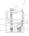
これらの図に示すように、本発明に係る遊技機試験装置に適用可能な遊技機は、複数のリール61a,61b,61cを回転させることによって遊技媒体であるメダルを獲得することができるスロットマシン50である。
スロットマシン50は、内部がマイクロコンピュータ等で構成された制御部及び必要な機械,装置等を収納可能な筐体状に構成されており、筐体1bの前面側が前扉1aによって開閉可能に覆われている。
前扉1aは、図1及び図2に示すように、スロットマシン1の筐体1bにヒンジ等を介して開閉自在に取り付けられる扉体で、この前扉1aに遊技操作に係る各装置等が備えられてスロットマシン50の正面部を構成している。
前扉1aのほぼ中央部分には、遊技者が操作するための操作部となる、メダル投入口2、スタートレバー3、BETボタン4、停止ボタン5等が備えられている。
Hereinafter, a preferred embodiment of a gaming machine testing apparatus according to the present invention will be described with reference to the drawings.
First, a gaming machine to which a gaming machine testing apparatus according to the present invention is applied will be described with reference to FIGS.
[Slot machine]
As shown in these drawings, the gaming machine applicable to the gaming machine testing apparatus according to the present invention is a slot machine that can acquire medals as gaming media by rotating a plurality of reels 61a, 61b, 61c. 50.
The
As shown in FIGS. 1 and 2, the front door 1a is a door body that can be freely opened and closed to a housing 1b of the slot machine 1 via a hinge or the like. The front portion of the
A
メダル投入口2は、遊技媒体となるメダルを投入する受入れ口である。
このメダル投入口2から投入されたメダルは、下流側に配置されたメダル検出装置(メダルセレクター)によって検出され、遊技に賭けるメダルとして制御部に記憶されるとともに、さらに誘導されて、後述のメダル払出装置7に設けられたホッパー7aに貯留される。
なお、制御部において記憶される(クレジット)メダル数は、最大50枚までとなっている。
The
The medal inserted from the
Note that the maximum number of (credit) medals stored in the control unit is 50.
メダルのBETボタン(投入ボタン)4は、制御部に記憶されているメダルがある場合に押下操作されると、そのメダルの中からゲームに賭けるメダルを投入(BET)するメダル投入用のスイッチである。
具体的には、一回の押下によって一ゲームに投入可能な最大数のメダル(通常3枚)を貯留メダルから投入する3枚賭け用のMAXBETボタン4aと、一回の押下で1枚のメダルを貯留メダルから投入する1枚賭け用の1BETボタン4bとが備えられている。
1BETボタン4bは一回押下するたびに1枚賭け、2枚賭け、3枚賭けとBET数が増加するようになっている。
BETボタン4が押下されると、各BETボタン4に対応したメダルが、制御部に記憶されたメダルから遊技に投入されることになる。
The medal BET button (insert button) 4 is a medal insertion switch that, when pressed down when there is a medal stored in the control unit, inserts (BET) a bet on the game from among the medals. is there.
Specifically, a
Each time the 1BET button 4b is pressed, one bet, two bets, three bets, and the number of BETs increase.
When the
スタートレバー3は、メダル投入口2から、又はBETボタン4の操作によって、遊技に賭けるメダルが投入されている場合に、上方又は下方に操作されることで、リール61a,61b,61cの回転を始動させるスイッチである。
このスタートレバー3が操作されると、制御部が、リール61a,61b,61cの回転を開始させるとともに、このタイミングで、小役やボーナスゲームなどを抽せんするための大当り乱数を取得する(内部抽せん)。
すなわち、スタートレバー3は、大当り乱数の取得に関与する操作部として機能するようになっている。
また、スタートレバー3の操作により、メダルの投入数に応じたパルス数を出力する、所謂スタート信号が外部情報端子板51から、スロットマシン50外部に出力される(図8参照)。
そして、この外部に出力されたスタート信号が遊技機試験装置10のコントローラ40に入力されることで、コントローラ40が、スロットマシン50の遊技状態を認識し、各操作端121〜123や投入装置20をスロットマシン遊技に同期させて駆動制御するようになっている。
The
When the
That is, the
Also, by operating the
Then, when the start signal output to the outside is input to the
停止ボタン5a,5b,5cは、各リール61を停止させるスイッチである。
各停止ボタン5は、各リール61に対応して設けられ、各リール61が回転しているときに押下操作されると、対応するリール61を停止させることができる。
The
Each stop button 5 is provided corresponding to each reel 61, and can be stopped when the corresponding reel 61 is pressed when the reel 61 is rotating.
前扉1aの下部には、メダルが排出されるメダル払出口8が設けられている。
このメダル払出口8からは、入賞時に払出されるメダルのみならず、制御部に記憶可能な最大メダル数が記憶されているときに投入されたメダルも排出されるようになっている。
A medal payout port 8 through which medals are discharged is provided at the lower part of the front door 1a.
From the medal payout port 8, not only medals paid out at the time of winning a prize, but also medals inserted when the maximum medal number that can be stored in the control unit is stored is discharged.
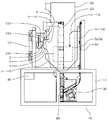
筐体1bの中央には、リール61a,61b,61cと、各リール61を回転させる図示しないステッピングモータ及び回転位置を検出するセンサなどを備えるドラムユニット6が設けられている。
ドラムユニット6は、制御部によって制御され、遊技に賭けるメダルが投入されているときに、スタートレバー3が操作されることで、各リール61を一斉に回転させ、また、停止ボタン5が操作されると、この操作タイミングと、制御部で行われた内部抽せん結果とに基づき、各リール61を停止させる。
In the center of the housing 1b, there is provided a drum unit 6 including
The drum unit 6 is controlled by the control unit, and when a medal to bet on a game is inserted, the
筐体1bの下部には、メダルを貯留・払出すメダル払出装置7が設けられている。各リール61に表された縦方向に連続する3つの図柄の組合せが所定の組合せで停止表示された場合に、このメダル払出装置7が作動して、所定数のメダルがメダル払出口8から払出される。
このとき、払出されたメダル数を示すメダル払出信号が外部に出力されるようになっている(図8参照)。
A
At this time, a medal payout signal indicating the number of medals paid out is output to the outside (see FIG. 8).
また、メダル払出装置7には、メダルを貯留するホッパー7aが設けられている。
ホッパー7aは、上方に開口した略矩形状の容器として形成されている。そして、メダル投入口2から投入され、メダル検出装置(メダルセレクター)で検出されたメダルが、このホッパー7aに貯留される。
また、筐体1bの裏面であって、ホッパー7aの近傍には、後述の補給装置30と連通する図示しない補給孔が穿設されており、この補給孔から、メダルがホッパー7aに補給されるようになっている。
The
The
Further, on the back surface of the housing 1b, in the vicinity of the
また、ホッパー7aには、貯留されたメダルの貯留数を検知する貯留数検出手段が設けられている。
この貯留数検出手段は、例えば、離間した二本の導電性のピンにより構成され、ホッパー7aがメダルで満杯になると、ピンがメダルによって短絡されることで、メダル満杯信号を外部に出力するように構成されている(図8参照)。
そして、この外部に出力されたメダル満杯信号が遊技機試験装置10のコントローラ40に入力されることで、コントローラ40が、分配装置34を制御し、補給装置30によってホッパー7aに補給されるメダルの一部を、投入装置20によって投入されるメダルに分配するようになっている。
The
This storage number detection means is constituted by, for example, two spaced apart conductive pins, and when the
Then, the medal full signal output to the outside is input to the
なお、貯留数検出手段が検出するメダルの貯留数は、ホッパー7aの満杯状態に限るものではなく、メダル払出装置7が、払出不能にならない程度の貯留数が検出できれば足りる。
また、貯留数検出手段は、一定量(数)のメダルが貯留されていることを検出できれば足り、上記の構成に限定されるものではない。例えば、貯留数検出手段を、メダルが一定量(数)の貯留されることで、メダルの重さや、貯留の高さによって作動するアクチュエータを有するマイクロスイッチとすることもできる。
また、コントローラ40が、後述する補給装置30が補給したメダル数から、投入装置20が投入したメダル数と、メダル払出信号に含まれるパルス数(払出数)とを減算して、スロットマシン50に貯留されているメダル数を算出してもよい。
Note that the number of stored medals detected by the stored number detection means is not limited to the
Further, the storage number detection unit is not limited to the above-described configuration as long as it can detect that a predetermined amount (number) of medals are stored. For example, the storage number detection means can be a micro switch having an actuator that operates according to the weight of the medal or the height of the storage when a predetermined amount (number) of medals are stored.
Further, the
また、ホッパー7aの近傍には、ホッパー7aと同様に上方に開口した略矩形状のオーバーフロータンク9が設けられている。
このオーバーフロータンク9は、満杯状態にあるホッパー7aから溢れたメダルが流入するように構成されるとともに、その底面は、溢れたメダルを回収可能なように外部と連通する図示しない回収孔が穿設されている。
Further, in the vicinity of the
The
[遊技機試験装置]
次に、上述のように構成されたスロットマシン50を、実際のメダルを用いて、無人で試験を行う本実施形態の遊技機試験装置10について、図3〜図11を参照して説明する。
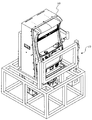
図3は、本実施形態に係る遊技機試験装置10の概略斜視図であり、図4は、正面図、図5は、平面図である。
図6は、スロットマシン50を設置した状態を示す右側面図であり、図7は、同じくスロットマシン50を設置した状態を示す概略斜視図である。
また、図8は、本実施形態に係る遊技機試験装置10とスロットマシン50の内部構成を示すブロック図である。
なお、図8の各矢印において、実線は、信号の流れ、一点鎖線は、メダルの流れ、破線は、動力の伝達方向を示している。
[Amusement machine testing equipment]
Next, the gaming
3 is a schematic perspective view of the gaming
6 is a right side view showing a state where the
FIG. 8 is a block diagram showing an internal configuration of the gaming
In each arrow in FIG. 8, the solid line indicates the signal flow, the alternate long and short dash line indicates the medal flow, and the broken line indicates the power transmission direction.
これらの図に示すように、本実施形態の遊技機試験装置10は、フレーム構造を有する枠11に、上述したスタートレバー3、BETボタン4、停止ボタン5などの各操作部に対応して設けられた操作端121〜123と、投入装置20と、補給装置30と、これらを制御するコントローラ40とを一体に取付けて構成されている。
As shown in these drawings, the gaming
枠11は、複数のアルミ製のL字材を、ネジ等を用いて螺着させたものであり、特に図示しないが底部に取付けられたキャスターによって、遊技機試験装置10を自在に移動することができるようになっている。
枠11の上部には、試験対象となるスロットマシン50を載置する載置部14が形成されている。
この載置部14は、スロットマシン50の底部両端が嵌合するL字状に形成され、スロットマシン50が揺動不能に載置される。
このように、フレーム構造を有する枠11に、各操作端121〜123、各装置20,30を取付けるとともに、スロットマシン50を載置することで、各々の動作状態を、視野を遮られることなく、観察できることから、スロットマシン50の動作を十分に確認できるとともに、メダル詰まり等のトラブル発生にいち早く対処できる。
The
On the upper part of the
The
As described above, the operation ends 121 to 123 and the
枠11の正面側には、支柱にヒンジ13を介して、開閉可能に取付けられた扉12が設けられている。
この扉12を開放することで、試験対象となるスロットマシン50を載置部14に設置し、又は、載置部14から取外すことができるようになっている。
On the front side of the
By opening the
扉12には、本発明の操作手段であるBET操作端121と、スタート操作端122と、停止操作端123a〜123cとが設けられている。
各操作端121〜123は、可動片と、この可動片を電磁力で駆動させるソレノイドなどで構成され、コントローラ40からのON/OFF信号によって、各ソレノイドが制御されることで、図6に示すように、各操作端121〜123に対応する操作部を操作することができるようになっている。
The
Each of the operation ends 121 to 123 includes a movable piece and a solenoid that drives the movable piece with electromagnetic force. The solenoids are controlled by an ON / OFF signal from the
具体的には、BET操作端121は、MAXBETボタン4aに対応して設けられ、コントローラ40からのON信号によって、可動片がMAXBETボタン4aを押下操作するように構成されている。
スタート操作端122は、スタートレバー3に対応して設けられ、コントローラ40からのON信号によって、可動片がスタートレバー3を押し上げ操作するように構成されている。
停止操作端123a〜123cは、停止ボタン5a〜5cに対応して設けられ、コントローラ40からのON信号によって、可動片が各停止ボタン5を押下操作するように構成されている。
Specifically, the
The
The stop operation ends 123a to 123c are provided corresponding to the
そして、各操作端121〜123は、各々扉12に独立して形成された図示しないガイド孔にネジ等で取付けられ、ガイド孔に沿って取付け位置を調整することがきるようになっている。このため、試験対象となるスロットマシンの操作部の位置に応じて、各操作端を独立して移動調整することができる。
Each
次に、投入装置20と補給装置30について説明する。
両装置20,30は、ほぼ同じ構成を有してなるため、最初に共通する構成について説明する。
両装置20,30には、メダルを貯留する貯留部21,31と、メダルを送出する送出部22,32と、メダルを上方に搬送する搬送部となるレール23,33とが共通に設けられている。
Next, the charging
Since both
Both
送出部22,32は、モータの回転力によってメダルを一枚ずつレール23,33に送出するとともに、レール23,33内に連なって滞在するメダルを上方に押し上げるように構成されている。
これにより、送出部22,32が、メダルを一枚送出する毎に、各レール23,33の先端に設けられた出口A〜Cから一枚のメダルが排出されるようになっている(図3参照)。
また、送出部22,32とレール23,33との間には、メダル検出部(不図示)が設けられ、送出するメダル数を計数することができるようになっている(本発明の計数手段)。
そして、このメダル検出部と送出部22,32は、コントローラ40に接続されている。これにより、コントローラ40は、メダル検出部からの検出信号を監視しつつ、送出部22,32を作動/停止制御することで、出口A〜Cから、メダルを一枚単位で排出することができる。
以下、補給装置30と投入装置20とを個別に説明する。
The sending
Thus, each time the sending
Further, a medal detection unit (not shown) is provided between the sending
The medal detection unit and the sending
Hereinafter, the replenishing
補給装置30は、本発明の補給手段であり、スロットマシン50のホッパー7aにメダルを補給する装置である。
補給装置30の貯留部31は、スロットマシン50のメダル払出口8と、オーバーフロータンク9の回収孔とに、ルートDを通るメダルが滑降可能なように構成されたメダル樋(不図示)によって連結されている。
このため、メダル払出装置7から払出されたメダルや、ホッパー7aが満杯となり、ホッパー7aから溢れたメダルは、貯留部31に漏れなく回収される。
The replenishing
The
For this reason, the medals paid out from the
貯留部31に回収されたメダルは、補給メダル送出部32の作動により、レール33を介して上方に搬送され、未作動状態となっている分配装置34を通過し、出口Aから排出される。
この出口Aから排出されたメダルは、ルートAを通るメダル樋(不図示)を滑降して、筐体1b裏面に穿設された補給孔からホッパー7aに補給されるようになっている。
そして、このような補給動作は、ホッパー7aの満杯状態を示すメダル満杯信号がコントローラ40に入力されるまで行われる。
このように、補給装置30は、スロットマシン50から払出されたメダルを再びスロットマシン50に補給するため、ホッパー7aが空になり、メダル払出装置7が払出し不能となることがない。
すなわち、メダル払出装置7を常時払出可能な状態とすることができるため、メダル払出装置7の耐久性や動作性能を十分試験することができるとともに、スロットマシン遊技を滞りなく進行させることができる。
The medals collected in the
The medals discharged from the exit A slide down a medal jar (not shown) passing through the route A, and are supplied to the
Such a replenishment operation is performed until a medal full signal indicating the full state of the
Thus, since the replenishing
That is, since the
また、補給装置30には、本発明の分配手段となる分配装置34が設けられている。
分配装置34は、レール33から出口Aに至る流路(経路)に設けられ、ソレノイド等を駆動源とし、未作動状態では、メダルを出口Aに誘導するとともに、作動によって、図示しないシャッターを開放させ、メダルを出口Bから排出する出口切替装置である。
分配装置34は、コントローラ40に接続され、メダル満杯信号がコントローラ40に入力されたときに作動し、メダルを出口Bから排出させる。
この出口Bから排出されたメダルは、ルートBを通るメダル樋(不図示)を滑降して、投入装置20の貯留部21に供給されるようになっている。
The replenishing
The
The
The medals discharged from the exit B slide down a medal basket (not shown) passing through the route B, and are supplied to the
このように、分配装置34が、ホッパー7aに貯留された貯留数に基づいて、補給装置30によってスロットマシン50に補給されるメダルの一部を、投入装置20によって投入されるメダルに分配するようになっている。
すなわち、メダル払出装置7が払出不能とならないメダル数をホッパー7aに確保しつつ、余ったメダルを投入装置20に分配している。そして、この余ったメダル数を遊技に賭けるために必要な最小限のメダル数とすれば、トータルで必要最低数のメダルを使用して、スロットマシン50の試験を滞りなく進行することができる。
Thus, the
In other words, the remaining medals are distributed to the
次に、投入装置20は、本発明の投入手段であり、コントローラ40によって制御されることで、遊技に賭ける必要数のメダルをメダル投入口2に投入する装置である。
投入装置20の貯留部21には、分配装置34によって分配され、出口BからルートBを経由したメダルが貯留される。
貯留部21に貯留されたメダルは、投入メダル送出部22の作動により、レール23を介して上方に搬送され、出口Cから排出される。
この出口Cから排出されたメダルは、ルートCを通り、図6に示すように、メダル投入口2に向けて投下される。
このとき投入されるメダル数は、コントローラ40にあらかじめ設定しておくことができる。
このように投入装置20を備えることで、メダル投入口2に、実際のメダルを投入することができるため、投入されたメダルを検出するメダル検出装置(メダルセレクター)の耐久性や動作性能を十分試験することができるとともに、スロットマシン遊技を滞りなく進行させることができる。
Next, the
In the
The medals stored in the
The medal discharged from the exit C passes through the route C and is dropped toward the
The number of medals inserted at this time can be set in the
By providing the
次に、コントローラ40は、図8に示すように、制御部45と、開始スイッチ42と、リセットスイッチ43と、スタート操作タイミング切替スイッチ44と、表示部41などを備え、制御部45の記憶手段に記憶されたプログラムに基づき、各操作端121〜123と投入装置20と補給装置30と分配装置34とを制御するコンピュータとして構成されている。
また、コントローラ40には、各操作端121〜123や各装置20,30,34に電源を供給する図示しない電源部も設けられている。
Next, as shown in FIG. 8, the
The
制御部45は、中央演算処理装置(CPU)や、プログラムやデータ、作業領域等の記憶手段(ROM、RAM)、各操作端121〜123や各装置20,30,34等と信号を送受するインターフェイス(I/Oポート)などを備えている。
開始スイッチ42は、遊技機試験装置50を起動させるスイッチであり、リセットスイッチ43は、トラブル発生時に遊技機試験装置50を初期化するスイッチである。
スタート操作タイミング切替スイッチ44は、スタート操作端122がスタートレバー3を操作するタイミングを選択するスイッチである。
The
The
The start operation
詳細には、スタート操作タイミング切替スイッチ44は、スタート操作端122の作動タイミングが一遊技毎一定となる固定時間モードと、一遊技毎に可変となる可変時間モードとのいずれかに切替えることができるスイッチである。
本実施形態では、可変時間モードを選択した場合、五種類の時間値が設定されており、一遊技毎に時間値を変更し、五ゲームで一巡するように制御している。
これにより、大当り乱数を取得するタイミングが幅を有することになり、取得される乱数値の均等(ランダム)性を確保することができる。
Specifically, the start operation
In this embodiment, when the variable time mode is selected, five types of time values are set, and the time value is changed for each game, and the game is controlled to make a round of five games.
Thereby, the timing for acquiring the big hit random number has a range, and the uniformity (randomness) of the acquired random number value can be ensured.
表示部41は、例えば、液晶表示器からなり、入力されたスタート信号とメダル払出信号との累積値を表示する。
すなわち、スタート信号の累積値から、遊技(ゲーム)回数を確認できるとともに、メダル払出信号の累積値から、スロットマシン50から払出されたメダルの総数を確認することができる。
The
That is, the number of games (games) can be confirmed from the accumulated value of the start signal, and the total number of medals paid out from the
次に、以上のように構成されたコントローラ40が、各操作端121〜123及び各装置20,30,34を制御する処理について、図9〜11を参照して説明する。
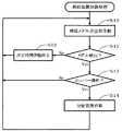
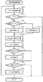
図9は、コントローラ40が補給装置30と分配装置34を制御する処理を示すフローチャートであり、図10及び11は、投入装置20と各操作端121〜123を制御する処理を示すフローチャートである。
Next, processing in which the
FIG. 9 is a flowchart illustrating a process in which the
最初に、補給装置30に関する補給装置制御処理について説明する。
補給装置制御処理では、開始スイッチ42がONされると、補給メダル送出部32を作動させる(S10)。これにより、貯留部31に貯留されているメダルがレール33に送出される。
次に、コントローラ40は、補給メダル送出部32とレール33との間に設けられたメダル検出部からの検出信号を監視し(S11)、メダルが検出されないときは(S11−NO)、所定時間補給メダル送出部32の作動を停止する(S12)。この場合には、所定時間後再び作動を開始する(S10)。これにより、貯留部31にメダルが貯留されていないときの空運転や、メダル詰まり等に起因するモータの焼付けを回避することができる。
一方、メダルが検出されたときは(S11−YES)、補給メダル送出部32を作動させつつ、メダル満杯信号の入力を監視する(S13)。
メダル満杯信号の入力がない場合は(S13−NO)、そのまま補給メダル送出部32を作動させる(S10)。これにより、ホッパー7aが満杯となるまでメダルを補給することができる。
メダル満杯信号の入力がある場合(S13−YES)、すなわち、ホッパー7aが満杯状態となると、分配装置34を作動させ(S14)、投入装置20の貯留部21にメダルを供給する。
First, the replenishing device control process related to the replenishing
In the replenishing device control process, when the
Next, the
On the other hand, when a medal is detected (S11-YES), the input of the medal full signal is monitored while the supply
If no medal full signal is input (S13-NO), the replenishment
When the medal full signal is input (S13-YES), that is, when the
このような制御処理により、メダル払出装置7が払出不能とならないメダル数をホッパー7aに確保しつつ、余ったメダルを投入装置20に分配することができる。
その結果、ホッパー7aが満杯状態となるメダル数と、投入装置20からメダル投入口2に投入される遊技に賭けるために必要なメダル数と、各レール23,33内に滞在するメダル数との合計が使用する総メダル数となり、必要最小限のメダルを循環させて、スロットマシン50の試験を進行させることができるようになっている。
With such a control process, the remaining medals can be distributed to the
As a result, the number of medals in which the
次に、投入装置20に関する投入装置制御処理について説明する。
投入装置制御処理では、開始スイッチ42がONされると、投入メダル送出部22を作動させる(S20)。これにより、貯留部21に貯留されているメダルがレール23に送出される。
そして、コントローラ40は、投入メダル送出部22とレール23との間に設けられたメダル検出部から入力された検出信号に基づき、送出したメダル数をカウントする。
メダル詰まり等により所定数(二回遊技分の賭け数:6枚)のメダルがカウントされないときは(S21−NO)、動作を停止させる(S22)。
所定数をカウントしたときには(S21−YES)、所定数のメダルがメダル投入口2に投入されたものとし、投入メダル送出部22の作動を停止する(S23)。
次に、各操作端121〜123を制御する操作端制御処理を行うことで、操作部を操作し、スロットマシン遊技を進行させる(S24)。
その後、停止していた投入メダル送出部22を再び作動させる(S20)。
Next, a charging device control process related to the charging
In the insertion device control process, when the
Then, the
When a predetermined number of medals is not counted due to clogged medals (6 bets for two games) (S21-NO), the operation is stopped (S22).
When the predetermined number is counted (S21-YES), it is assumed that a predetermined number of medals have been inserted into the
Next, by performing an operation end control process for controlling the operation ends 121 to 123, the operation unit is operated to advance the slot machine game (S24).
Thereafter, the inserted medal sending section 22 that has been stopped is operated again (S20).
次に、BET操作端121、スタート操作端122、停止操作端123a〜123cを制御する操作端制御処理について説明する。
操作端制御処理は、上記の投入装置制御処理が呼出元となる制御処理であり、スタート信号の入力に基づき、あらかじめ定められた時間の間隔をもって各ステップS30〜S40を順次行う。
あらかじめ定められた時間の間隔をもって各ステップを行うのは、スロットマシンの場合、メダル投入又はBET操作、スタートレバー3操作(スタート信号出力)、リール61の回転開始、停止ボタン5の操作有効、停止ボタン5操作によるリール61の停止、メダル払出に至るまで、あらかじめ定められた時間の推移に従って遊技を進行させることができるように構成されているためである。
そして、遊技が可能となるメダル数が投入されているときにスタートレバー3が操作されることで、スロットマシン50からスタート信号が入力されることから、コントローラ40は、このスタート信号の入力タイミングに基づき、スロットマシン50の遊技状態(リール61の回転開始)を認識することができる。
すなわち、コントローラ40は、スタート信号の入力タイミングを監視することで、BET操作端121、スタート操作端122、停止操作端123a〜123cと投入装置20を、スロットマシン50の遊技状態に同期させて駆動制御できる。
Next, an operation end control process for controlling the
The operation end control process is a control process in which the above-described input device control process is a caller, and steps S30 to S40 are sequentially performed at predetermined time intervals based on the input of the start signal.
In the case of a slot machine, each step is performed at predetermined time intervals. In the case of a slot machine, a medal insertion or BET operation, a
The start signal is input from the
That is, the
本実施形態の操作端制御処理では、スロットマシン遊技を二回分行うようになっている。
具体的には、既に、呼出元である投入装置制御処理において、二回遊技分の賭け数となる6枚のメダルが投入され、遊技可能な状態になっているとして、まず、スタート操作端122を作動させ、スタートレバー3を操作する(S30)。
そして、スタート信号の入力を監視し(S31)、スタート信号の入力がないときには(S31−NO)、遊技可能となる必要数のメダルが投入されていないものとし、呼出元である投入装置制御処理に戻り、投入装置制御処理において、投入メダル送出部22を作動させ、メダルを投入させる。これにより、必要数のメダルを確実に投入することができる。
In the operation end control process of the present embodiment, slot machine games are performed twice.
Specifically, in the insertion device control process that is the calling source, it is assumed that six medals that are the number of bets for two games have already been inserted and are ready for gaming. And the
Then, the input of the start signal is monitored (S31), and when there is no input of the start signal (S31-NO), it is assumed that the necessary number of medals that can be played are not inserted, and the insertion device control process that is the calling source Returning to FIG. 2, in the insertion device control process, the inserted medal sending unit 22 is operated to insert a medal. Thereby, a required number of medals can be inserted reliably.
一方、スタート信号の入力があるときには(S31−YES)、各リール61が回転を開始したものと判断できることから、以下の処理を順次行う。
まず、スタート操作タイミング切替スイッチ44の状態を監視する(S32)。
そして、スタート操作タイミング切替スイッチ44がオフ状態、すなわち固定時間モードが選択されている場合は(S32−NO)、設定された固定時間を計時する(S33)。一方、オン状態、すなわち、可変時間モードが選択されている場合は(S32−YES)、五ゲームで一巡する五種類の可変時間のうち、一の可変時間を計時する(S34)。これにより、可変時間モードが選択されている場合、以後の各ゲームにおけるスタートレバー3の操作タイミングにずれを生じさせることができ、取得する乱数値にバラツキをもたせることができる。
On the other hand, when there is an input of a start signal (S31-YES), it can be determined that each reel 61 has started rotating, so the following processing is performed in sequence.
First, the state of the start
When the start operation
その後、一定の間隔をおいて、停止操作端123a〜123cを、所定の順番で作動させて、各リール61を停止させるとともに(S35)、スタート信号を累積したスタート数を表示部41に表示させる(S36)。
次に、メダル払出信号の入力を監視し(S37)、入力があったときは(S37−YES)、メダル払出信号に包含されたパルス数を、前回の払出数に累積した今回の払出数を表示部41に表示させ(S38)、所定時間入力がないときは(S37−NO)、前回の払出数を表示部41に表示する。
Thereafter, the stop operation ends 123a to 123c are operated in a predetermined order at regular intervals to stop each reel 61 (S35), and the start number in which the start signals are accumulated is displayed on the
Next, the input of the medal payout signal is monitored (S37). When there is an input (S37-YES), the number of pulses currently included in the number of pulses included in the medal payout signal is accumulated to the previous payout number. Displayed on the display unit 41 (S38), and when there is no input for a predetermined time (S37-NO), the previous payout number is displayed on the
次に、今回の遊技が一回目の遊技か、二回目の遊技かを判定し(S39)、一回目の遊技の場合は(S39−NO)、BET操作端121を作動させ、MAXBETボタン4aを操作した後(S40)、再びスタート操作端122を作動させる(S30)。
このような処理は、上述したように、呼出元である投入装置制御処理において、二回遊技分の賭け数となる6枚のメダルが投入され、スロットマシン50の制御部に遊技に賭けるための必要数のメダルが記憶されている(クレジット)ことを前提として、MAXBETボタン4aを操作している。ところが、実際には投入されず、遊技に賭けるための必要数のメダルが記憶されていないこともあるため、この場合は、次のスタート信号の入力監視において(S31)、入力がないので(S31−NO)、再び呼出元である投入装置制御処理において、投入メダル送出部22を作動させ、メダルを投入させるようになっている。
一方、今回の遊技が二回目の遊技の場合は(S39−YES)、再び呼出元である投入装置制御処理に戻る。
Next, it is determined whether the current game is the first game or the second game (S39). If it is the first game (S39-NO), the
As described above, in such a process, in the insertion device control process that is a caller, six medals that are the number of bets for two games are inserted, and the control unit of the
On the other hand, if the current game is the second game (S39-YES), the process returns to the input device control process that is the calling source.
このように操作端制御処理では、BET操作端121、スタート操作端122、停止操作端123a〜123cを制御して、MAXBETボタン4a、スタートレバー3、停止ボタン5a〜5cを操作しているため、遊技操作に係る操作部の耐久性や動作確認を漏れなく行うことができる。
また、コントローラ40が、スタート信号の入力タイミングに基づき、スロットマシン50の遊技状態を認識しつつ、各操作端121〜123を操作するため、最小単位のサイクル時間でスロットマシン遊技を進行させることができ、試験時間の短縮を図ることができる。
さらに、スタート信号の入力を監視しつつ、投入装置20を制御することから、むやみにメダルを投入する事態が回避され、投入装置20の貯留部21に大量のメダルを確保する必要がない。つまり、必要最小数の投入メダル数があれば、滞りなく試験を進行させることができる。
また、コントローラ40は、メダル投入装置20が投入したメダル数とメダル払出信号とからスロットマシン50の制御部に記憶されているメダル数(クレジット数)を、判定できることから、記憶されているメダル数に応じて、メダル投入装置20を制御するとともに、MAXBETボタン4aを操作するBET操作端121を制御してもよい。これにより、本実施形態では、二回の遊技に一回の割合でメダルを投入しているが、メダルを投入する頻度を少なくすることができ、投入装置20の貯留部21に確保するメダル数をさらに少なくすることができる。
Thus, in the operation end control process, the
Further, since the
Furthermore, since the
Further, since the
以上述べたように、本実施形態の遊技機試験装置10は、スタートレバー3、BETボタン4、停止ボタン5などの各操作部に対応して設けられた操作端121〜123と、投入装置20と、補給装置30と、分配装置34と、これらを制御するコントローラ40とを一体に取付けて構成されていることから、各操作部の操作に加え、実際のメダルを使用し、メダルの投入から不足したメダルの補給までを、必要最低数のメダルを用いて、無人状態で行うことができる。
As described above, the gaming
以上、本発明のスロットマシンの好ましい実施形態について説明したが、本発明に係るスロットマシンは上述した実施形態にのみ限定されるものではなく、本発明の範囲で種々の変更実施が可能であることはいうまでもない。 The preferred embodiment of the slot machine of the present invention has been described above, but the slot machine according to the present invention is not limited to the above-described embodiment, and various modifications can be made within the scope of the present invention. Needless to say.
例えば、本実施形態では、各操作端や、分配装置の駆動源としてソレノイドを使用したが、モータを用いてよい。
また、本実施形態では、コントローラを遊技機試験装置に一体に取り付けたが、別体としてもよい。また、コントローラは、専用品でなく、例えば、汎用のパーソナルコンピュータを用いることもできる。
For example, in the present embodiment, a solenoid is used as each operation end and a drive source of the distributor, but a motor may be used.
In this embodiment, the controller is integrally attached to the gaming machine testing device, but may be a separate body. Further, the controller is not a dedicated product, and for example, a general-purpose personal computer can be used.
本発明は、メダルを使用して遊技が行われるスロットマシン(回胴式遊技機)の試験装置として好適に利用することができる。 INDUSTRIAL APPLICABILITY The present invention can be suitably used as a test apparatus for a slot machine (rotating game machine) in which a game is played using medals.
10 遊技機試験装置
20 投入装置
30 補給装置
34 分配装置
40 コントローラ
50 スロットマシン
DESCRIPTION OF
Claims (10)
遊技機の操作部を操作する操作手段と、
遊技機に遊技媒体を補給する補給手段と、
遊技に賭ける遊技媒体を当該遊技機に投入する投入手段と、を一体に備えることを特徴とする遊技機試験装置。 A gaming machine testing device that operates a gaming machine unattended,
Operating means for operating the operating unit of the gaming machine;
Replenishment means for replenishing gaming machines with game media;
A gaming machine testing device, comprising: a loading unit that loads gaming media to bet on a game into the gaming machine.
遊技媒体を貯留する貯留部と、
貯留した遊技媒体を送出する送出部と、
送出された遊技媒体を上方に搬送する搬送部と、を備える請求項1又は2記載の遊技機試験装置。 The replenishing means and the charging means are:
A storage unit for storing game media;
A sending unit for sending the stored game media;
The gaming machine testing device according to claim 1, further comprising: a transport unit configured to transport the sent game medium upward.
前記分配手段は、前記経路に設けられ、所定の駆動手段により駆動されて、前記出口をいずれかに切替える請求項5記載の遊技機試験装置。 A plurality of outlets through which game media are discharged in a path for supplying game media to the gaming machine;
The gaming machine testing device according to claim 5, wherein the distribution unit is provided in the path, and is driven by a predetermined driving unit to switch the outlet to any one of them.
前記分配手段が、前記貯留数に基づいて前記補給手段によって遊技機に補給される遊技媒体の一部を、前記投入手段によって投入される遊技媒体に分配する請求項5又は6記載の遊技機試験装置。 A storage number detecting means for detecting the number of stored game media stored in the gaming machine;
The gaming machine test according to claim 5 or 6, wherein the distribution means distributes a part of the game medium supplied to the gaming machine by the supply means to the game medium input by the input means based on the storage number. apparatus.
Priority Applications (1)
| Application Number | Priority Date | Filing Date | Title |
|---|---|---|---|
| JP2008271745A JP5282250B2 (en) | 2008-10-22 | 2008-10-22 | Game machine testing equipment |
Applications Claiming Priority (1)
| Application Number | Priority Date | Filing Date | Title |
|---|---|---|---|
| JP2008271745A JP5282250B2 (en) | 2008-10-22 | 2008-10-22 | Game machine testing equipment |
Publications (2)
| Publication Number | Publication Date |
|---|---|
| JP2010099166A true JP2010099166A (en) | 2010-05-06 |
| JP5282250B2 JP5282250B2 (en) | 2013-09-04 |
Family
ID=42290341
Family Applications (1)
| Application Number | Title | Priority Date | Filing Date |
|---|---|---|---|
| JP2008271745A Expired - Fee Related JP5282250B2 (en) | 2008-10-22 | 2008-10-22 | Game machine testing equipment |
Country Status (1)
| Country | Link |
|---|---|
| JP (1) | JP5282250B2 (en) |
Cited By (2)
| Publication number | Priority date | Publication date | Assignee | Title |
|---|---|---|---|---|
| JP2019188078A (en) * | 2018-04-28 | 2019-10-31 | 株式会社大都技研 | Game machine |
| JP2020168227A (en) * | 2019-04-04 | 2020-10-15 | 日本ノーベル株式会社 | Inspection system, inspection method and inspection program for reel type game machine |
Citations (1)
| Publication number | Priority date | Publication date | Assignee | Title |
|---|---|---|---|---|
| JP2006175171A (en) * | 2004-12-24 | 2006-07-06 | Eternal Fortune:Kk | Trial hitting device for pachinko game machine |
-
2008
- 2008-10-22 JP JP2008271745A patent/JP5282250B2/en not_active Expired - Fee Related
Patent Citations (1)
| Publication number | Priority date | Publication date | Assignee | Title |
|---|---|---|---|---|
| JP2006175171A (en) * | 2004-12-24 | 2006-07-06 | Eternal Fortune:Kk | Trial hitting device for pachinko game machine |
Cited By (4)
| Publication number | Priority date | Publication date | Assignee | Title |
|---|---|---|---|---|
| JP2019188078A (en) * | 2018-04-28 | 2019-10-31 | 株式会社大都技研 | Game machine |
| JP7125095B2 (en) | 2018-04-28 | 2022-08-24 | 株式会社大都技研 | Game stand durability tester |
| JP2020168227A (en) * | 2019-04-04 | 2020-10-15 | 日本ノーベル株式会社 | Inspection system, inspection method and inspection program for reel type game machine |
| JP7137217B2 (en) | 2019-04-04 | 2022-09-14 | 日本ノーベル株式会社 | Inspection system, inspection method and inspection program for reel-type game machines |
Also Published As
| Publication number | Publication date |
|---|---|
| JP5282250B2 (en) | 2013-09-04 |
Similar Documents
| Publication | Publication Date | Title |
|---|---|---|
| JP2008246061A (en) | System for processing fraudulent putout of token, method for processing fraudulent putout of token and game machine | |
| WO2006025476A1 (en) | Game machine | |
| JP2009219545A (en) | Game machine | |
| JP2012187387A (en) | Game machine | |
| JP2007037880A (en) | Game machine | |
| JP4860304B2 (en) | Game machine | |
| JP5282250B2 (en) | Game machine testing equipment | |
| JP2006346157A (en) | Game machine | |
| JP2003310835A (en) | Slot machine | |
| JP2008246059A (en) | System for error processing for fraudulent putout of token, method for error processing for fraudulent putout of token and game machine | |
| JP2007215625A (en) | Game machine | |
| JP3213073B2 (en) | Ball game machine | |
| JP2009045206A (en) | Pachinko game machine | |
| JP5030220B2 (en) | Gaming machine and payout control method | |
| JP2018175014A (en) | Token game machine | |
| JP5897193B1 (en) | Game machine | |
| JPH06277348A (en) | Pachinko game machine | |
| JP2579287B2 (en) | Ball game machine | |
| JP2004105280A (en) | Pachinko game machine | |
| JP2003190379A (en) | Game machine | |
| JP2003024594A (en) | Game machine | |
| JP2008246060A (en) | Token fraudulent putout error processing system, token fraudulent putout error processing method and game machine | |
| JPH1157155A (en) | Pachinko game machine | |
| JP2006116017A (en) | Game machine | |
| JP2579287C (en) |
Legal Events
| Date | Code | Title | Description |
|---|---|---|---|
| A621 | Written request for application examination |
Free format text: JAPANESE INTERMEDIATE CODE: A621 Effective date: 20111005 |
|
| A977 | Report on retrieval |
Free format text: JAPANESE INTERMEDIATE CODE: A971007 Effective date: 20130130 |
|
| A131 | Notification of reasons for refusal |
Free format text: JAPANESE INTERMEDIATE CODE: A131 Effective date: 20130205 |
|
| A521 | Request for written amendment filed |
Free format text: JAPANESE INTERMEDIATE CODE: A523 Effective date: 20130328 |
|
| TRDD | Decision of grant or rejection written | ||
| A01 | Written decision to grant a patent or to grant a registration (utility model) |
Free format text: JAPANESE INTERMEDIATE CODE: A01 Effective date: 20130416 |
|
| A61 | First payment of annual fees (during grant procedure) |
Free format text: JAPANESE INTERMEDIATE CODE: A61 Effective date: 20130423 |
|
| R150 | Certificate of patent or registration of utility model |
Ref document number: 5282250 Country of ref document: JP Free format text: JAPANESE INTERMEDIATE CODE: R150 |
|
| R250 | Receipt of annual fees |
Free format text: JAPANESE INTERMEDIATE CODE: R250 |
|
| LAPS | Cancellation because of no payment of annual fees |