JP2010089433A - Resin supply device - Google Patents
Resin supply device Download PDFInfo
- Publication number
- JP2010089433A JP2010089433A JP2008263208A JP2008263208A JP2010089433A JP 2010089433 A JP2010089433 A JP 2010089433A JP 2008263208 A JP2008263208 A JP 2008263208A JP 2008263208 A JP2008263208 A JP 2008263208A JP 2010089433 A JP2010089433 A JP 2010089433A
- Authority
- JP
- Japan
- Prior art keywords
- resin
- powdery
- conveyance path
- supply device
- sealing
- Prior art date
- Legal status (The legal status is an assumption and is not a legal conclusion. Google has not performed a legal analysis and makes no representation as to the accuracy of the status listed.)
- Granted
Links
Images


Abstract
Description
本発明は、被成形品を樹脂封止する樹脂封止装置に用いられる樹脂供給装置の技術分野に関する。 The present invention relates to a technical field of a resin supply device used in a resin sealing device for resin-sealing a molded product.
被成形品である半導体チップ等を配置した基板を樹脂にて封止する樹脂封止装置に対して、粉体状の樹脂を供給する場合がある。粉体状の樹脂を供給する装置として、図5に示す樹脂供給装置90が知られている(特許文献1参照)。
In some cases, a powdery resin is supplied to a resin sealing device that seals a substrate on which a semiconductor chip or the like, which is a molded product, is arranged with resin. As an apparatus for supplying powdery resin, a
樹脂供給装置90は、供給フィーダ本体91と平型ノズル94とを備える。供給フィーダ本体91は、電子天秤96の上に配置された支柱98に対して、粉体状の樹脂80が供給されるホッパ92と、粉体状の樹脂80の出口となる筒状の供給ノズル93と、を有する。支柱98には振動子95が設けられている。また、電子天秤96及び振動子95には、演算装置97が接続されている。供給ノズル93から供給された粉体状の樹脂80は、平型ノズル94により樹脂供給先であるキャビティ40に供給される。粉体状の樹脂80の供給は、演算装置97からの指令で、支柱98に設置された振動子95が振動することによって行われる。このとき、電子天秤96によって計量される計量値が減少する。この減少した量を演算装置97によって検知した上で、所定のタイミングで振動子95の振動を止めることで、供給を停止させている。このような構成及び作用によって、当該樹脂供給装置90は、粉体状の樹脂80を計量して供給することができる。
The
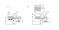
ここで、特許文献1に記載の供給フィーダ本体91を模式的に表すと、図6の如く示すことができる(図5では、供給ノズル93は、水平方向から傾きを有していたが、図6(A)、(B)では水平としている)。粉体状の樹脂80の計量・供給方法は、供給フィーダ本体91の動作中に粉体状の樹脂80を計量を行い(図6(A))、停止指令がかかった時点で振動子95を停止させるものである(図6(B))。しかし、振動子95の振動を止めても、粉体状の樹脂80の落下はすぐには止まらず、落下量に誤差(主に図6(B)の符合80Aの部分で構成され、落差量80Aと称する)を生じる。この落差量80Aの影響により、精密な計量は困難であった。
Here, the supply feeder
このため、落差量80Aの影響を低減するために、供給ノズル93中の流動量を少なくすることが考えられる。即ち、図6(A)、(B)に示す高さhを低くするものである。この場合には、落差量80Aが減少するが、流動量も少なくなってしまう。流動量が減ると、樹脂封止装置の生産性を下げるおそれがあり、更に悪くすれば、粉体状の樹脂80の量が適切に供給されずに樹脂封止の品質を悪化させるおそれもある。粉体状の樹脂80の計量精度を保つことは樹脂封止品質を保つことにつながるが、粉体状の樹脂80の計量速度を落とさずに計量精度を向上させることは困難であった。
For this reason, in order to reduce the influence of the
本発明は、このような観点から、粉体状の樹脂の計量速度を落とさずに計量精度を向上させて、樹脂封止装置の生産性を低下させることなく、歩留りの高い高品質な樹脂封止を可能とする樹脂供給装置を提供することをその目的としている。 From this point of view, the present invention improves the measurement accuracy without reducing the measurement speed of the powdered resin, and does not reduce the productivity of the resin sealing device. An object of the present invention is to provide a resin supply device that can be stopped.
本発明は、被成形品を樹脂封止する樹脂封止装置に対して、該樹脂封止のために粉体状の樹脂を供給する樹脂供給装置であって、前記粉体状の樹脂が投入される該粉体状の樹脂を自身の先端部分まで搬送し該先端部分より落下させる樹脂搬送路と、該樹脂搬送路を振動させる振動手段と、を備え、前記樹脂搬送路の先端部分が、水平方向に対して前記粉体状の樹脂の安息角で成形されていることで、上記課題を解決するものである。 The present invention relates to a resin supply device for supplying a powdery resin for resin sealing to a resin sealing device for resin-sealing a product to be molded. A resin transport path that transports the powdered resin to its tip portion and drops from the tip portion, and a vibration means that vibrates the resin transport path, the tip portion of the resin transport path, The above-mentioned problem is solved by molding at an angle of repose of the powdery resin with respect to the horizontal direction.
出願人は、精密な計量のために、供給フィーダ本体の従来の制御方法の改良に着目するのではなく、落差量の原因となる物理現象に着目し、その現象を積極的に活用しようとした。即ち、本発明は、落差量を生じた後の樹脂搬送路の先端部分での粉体状の樹脂の状態に着眼点を有するもので、樹脂搬送路に保持される粉体状の樹脂が自発的にくずれることなく安定を保って堆積した際の水平方向となす角度(安息角と称する)で、樹脂搬送路の先端部分を予め成形したものである。 The applicant did not pay attention to the improvement of the conventional control method of the supply feeder body for precise weighing, but focused on the physical phenomenon causing the head drop, and tried to use the phenomenon positively. . That is, the present invention focuses on the state of the powdery resin at the tip of the resin conveyance path after the drop amount is generated, and the powdery resin held in the resin conveyance path is spontaneous. The front end portion of the resin conveyance path is preliminarily molded at an angle (referred to as an angle of repose) formed in the horizontal direction when depositing while maintaining stability without breaking down.
このような構成を採用した結果、振動子の動作を停止した時点で、既に安息角以上の角度には粉体状の樹脂が樹脂搬送路上で残存しないので、落差量を低減することができる。即ち、粉体状の樹脂の流動量が多くても、落差量を少なくすることができるので、粉体状の樹脂の計量をする際には計量速度を落とさずに計量精度を向上させることができる。 As a result of adopting such a configuration, when the operation of the vibrator is stopped, since the powdery resin does not remain on the resin conveyance path at an angle equal to or greater than the repose angle, the drop amount can be reduced. That is, even if the amount of powdered resin flow is large, the amount of drop can be reduced, so that when measuring powdered resin, the measurement accuracy can be improved without reducing the measuring speed. it can.
又、前記粉体状の樹脂が投入された位置から前記先端部分の位置までの前記樹脂搬送路の区間に、前記粉体状の樹脂の流動量を制限するための絞り機構が設けられている場合には、樹脂封止に用いるのに最適な粉体状の樹脂の量の流動を実現することが可能となる。 In addition, a squeezing mechanism for restricting the flow amount of the powdery resin is provided in a section of the resin transport path from the position where the powdery resin is charged to the position of the tip portion. In this case, it is possible to realize the flow of the amount of powdery resin that is optimal for use in resin sealing.
又、前記樹脂搬送路の断面がV字形状である場合には、樹脂搬送路の断面がコの字形状である場合に比べて、流動量を制御しやすくなるので、安定して粉体状の樹脂を計量することが可能である。 In addition, when the cross section of the resin conveyance path is V-shaped, the flow amount can be controlled more easily than in the case where the cross section of the resin conveyance path is U-shaped. It is possible to weigh the resin.
本発明を適用することにより、粉体状の樹脂の計量をする際には計量速度を落とさずに計量精度を向上させて、樹脂封止装置の生産性を低下させることなく、樹脂封止装置の性能を向上させることができ、歩留りの高い高品質な樹脂封止が可能となる。 By applying the present invention, when measuring powdered resin, the resin sealing device can improve the measurement accuracy without reducing the measuring speed, and without reducing the productivity of the resin sealing device. Performance can be improved, and high-quality resin sealing with a high yield becomes possible.
以下、添付図面を参照しつつ、本発明の実施形態の一例について詳細に説明する。 Hereinafter, an example of an embodiment of the present invention will be described in detail with reference to the accompanying drawings.
図1は本発明の実施形態に係わる樹脂封止装置の一例を示す模式図((A)は上面図、(B)は正面図)、図2は同じく金型の一例を示す模式図、図3は同じく樹脂供給装置の一例を示す模式図、図4は同じく供給フィーダ本体の拡大模式図((A)は側面図、(B)は(A)の矢視図)、である。 FIG. 1 is a schematic view showing an example of a resin sealing device according to an embodiment of the present invention ((A) is a top view, (B) is a front view), and FIG. 2 is a schematic view showing an example of a mold. 3 is a schematic view showing an example of a resin supply device, and FIG. 4 is an enlarged schematic view of the supply feeder main body ((A) is a side view, and (B) is an arrow view of (A)).
最初に、本発明の実施形態に係わる樹脂供給装置の概略について以下に説明する。 First, an outline of a resin supply apparatus according to an embodiment of the present invention will be described below.
樹脂供給装置150は、被成形品である半導体チップ104が配置された基板102を樹脂封止する樹脂封止装置100に対して、樹脂封止のために粉体状の樹脂106を供給する。なお、複数の半導体チップ104を配置した一枚の基板102は、樹脂封止装置100によって一度に樹脂封止される。
The
そして、樹脂供給装置150は、供給フィーダ本体152において、図3に示す如く、粉体状の樹脂106が投入され粉体状の樹脂106を自身の先端部分156Aまで搬送し先端部分156Aより落下させる樹脂搬送路156と、樹脂搬送路156を振動させる振動手段である振動子160と、を備える。ここで、樹脂搬送路156の先端部分156Aは、水平方向に対して粉体状の樹脂106の安息角θで成形されている。
Then, as shown in FIG. 3, in the supply feeder main body 152, the
以下に、本発明の実施形態に係わる樹脂封止装置の各構成要素について説明する。 Below, each component of the resin sealing apparatus concerning embodiment of this invention is demonstrated.
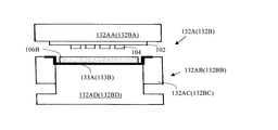
樹脂封止装置100は、図1に示す如く、マガジンユニット110と、基板予熱ユニット120と、プレスユニット130と、樹脂打錠ユニット140と、を有する。
As shown in FIG. 1, the resin sealing device 100 includes a
マガジンユニット110は、図1に示す如く、樹脂封止がされていない基板102を供給するための供給マガジン112Aと、樹脂封止された基板102を収納するための収納マガジン112Bと、を有して、互いに上下方向で位置を異ならせている(図1(B)参照)。基板102はマガジンエレベータ114を介して供給マガジン112Aから引き出される。そして、引き出された基板102は基板予熱ユニット120に送られる。なお、基板102が引き出された際に、図示せぬ認識手段であるカメラあるいはレーザセンサにより基板102上の半導体チップ104の数が認識される。
As shown in FIG. 1, the
基板予熱ユニット120は、複数の基板予熱レールから構成される。基板102が予熱された後に、その基板102が、樹脂封止装置100のX方向に敷設された移動ガイド136上のX方向に移動可能な基板ローダ/アンローダ124によってプレスユニット130に送られる。
The
プレスユニット130は、図1に示す如く、複数の金型(本実施形態においては、2つの金型130A、130B)から構成される。金型130A、130Bはそれぞれ、図2に示す如く、上型132AA、132BAと下型132AB、132BBとから構成される。下型132AB、132BBには可動プラテン(図示しない)が連結されており、所定のタイミングで下型132AB、132BBを上型132AA、132BAに対して接近、離反することが可能とされている。下型132AB、132BBは、貫通孔を備えた枠状金型132AC、132BCと当該貫通孔に嵌合して配置される圧縮金型132AD、132BDとを有している。下型132AB、132BBの表面には、下枠フィルム133A、133Bが図示せぬ供給機構によって案内され、所定のタイミングで順次送られて使用される。
As shown in FIG. 1, the
図2に示す如く、樹脂封止の際には、基板102は、上型132AA、132BAに備わる吸着機構(図示しない)によって吸着保持される。そして、樹脂打錠ユニット140から予備成形された樹脂106Bが、下型132AB、132BBの表面に形成されたキャビティに投入され樹脂封止される。樹脂封止される基板102上には複数の半導体チップ104が配置されており、これらの複数の半導体チップ104が一度に樹脂封止される。樹脂封止作業が終了すると、上型132AA、132BAと下型132AB、132BBとは可動プラテンによって離反(型開き)される。樹脂封止された基板102は、下枠フィルム133A、133Bの存在によって下型132AB、132BBから容易に取り外せるため、上型132AA、132BAに吸着保持された態様で取り出される。このように、金型132A、132Bを用いて樹脂封止することで、溶融した樹脂をキャビティの外部から圧力によって流し込む所謂「トランスファ方式」のものに比べて、樹脂流れを少なくできるので、ボンディングワイヤの断線、短絡が発生する可能性を低減することが可能である。特に近年の半導体チップ104等の薄肉化、小型化により、係る利点はより顕著となっている。
As shown in FIG. 2, at the time of resin sealing, the
樹脂打錠ユニット140は、図1に示す如く、粉体状の樹脂106を予備成形するためのフィルム搬送部142と、予備形成された樹脂106Bを計量して、樹脂投入ハンド134に樹脂106Bを搭載するための樹脂搬送部144と、を有する。
As shown in FIG. 1, the
フィルム搬送部142には、図1に示す如く、Y方向に移動可能なフィルム148が配置されている。フィルム148のY方向の位置毎に、粉体状の樹脂106の供給、加熱、冷却が行われ、粉体状の樹脂106が予備成形される。粉体状の樹脂106は、樹脂供給装置150で計量されてフィルム148に供給される。
As shown in FIG. 1, a
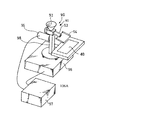
樹脂供給装置150は、図1で示すフィルム搬送部142の粉体状の樹脂106が供給される位置の真上に配置されている。樹脂供給装置150は、図3に示す如く、粉体状の樹脂106を樹脂封止のためにカメラあるいはレーザセンサの認識による半導体チップ104の数に基づいて計量して供給する供給フィーダ本体152と、計量された粉体状の樹脂106を一時的に収納するカップ166を複数備えるカップテーブル164と、カップ166が反転して落下する粉体状の樹脂106をフィルム148上に均一な厚みで拡散させるシュート168とを備える。
The
供給フィーダ本体152は、図3に示す如く、ホッパ154と樹脂搬送路156と振動子160と重量センサ162とを有する。ホッパ154は、下方にいくに従い狭まる形状の容器であり、粉体状の樹脂106が投入された後に、当該粉体状の樹脂106を保持する。樹脂搬送路156は、ホッパ154の側面に連結されると共に、水平方向(図4(A)中の矢印方向)に伸びるV字形状の断面(図4(B)参照)を有する樋であり、粉体状の樹脂106をホッパ154から自身の先端部分156Aに導く。樹脂搬送路156の先端部分156Aは、少なくとも樹脂搬送路156の下面から粉体状の樹脂106の流動する高さh1までの範囲が水平方向(図4(A)中の矢印方向)に対して粉体状の樹脂106の安息角θで成形されている。
As shown in FIG. 3, the supply feeder main body 152 includes a hopper 154, a
安息角θは、図4(A)に示す如く、実際に粉体状の樹脂106を落下させて堆積させたときに、自発的に崩れることなく、水平方向とその粉体状の樹脂106の堆積物106Aの斜面とがなす角度を観察することで、容易に求めることができる。このため、粉体状の樹脂106に対して、例えば作業現場で先端部分156Aを加工することもできる。また、加工する際にも、樹脂搬送路156の断面がV字形状なので、先端部分156Aを安息角θとして的確に切り出すことが容易である。同時に、落下する粉体状の樹脂106は、樹脂搬送路156の外壁の表面部分には付着しにくく、落差量をより少なくすることができる。なお、安息角θの加工精度は求められる安息角に対して±5度程度で許容することを目安とする。この程度の角度誤差であれば、計量精度に与える影響は少ないからである。粉体状の樹脂106の安息角θがばらつく際には、そのばらつきの平均をとって、安息角θを求めてもよい。本実施形態においては、粉体状の樹脂106の粒径0.01m〜2mmのものを使用し、安息角θとして45度を求めることができたので、その角度θで樹脂搬送路156の先端部分156Aを加工している。なお、粉体状の樹脂106の材質や粒径が異なれば、その物性値の変化に従い、別の安息角θを求めることとなる。
As shown in FIG. 4 (A), the angle of repose θ does not collapse spontaneously when the
図3に示す如く、粉体状の樹脂106が投入された位置である樹脂搬送路156のホッパ154の位置から、樹脂搬送路156の先端部分156Aの位置までの区間に、樹脂搬送路156の内壁との間で絞り機構を構成する絞り部材158を配置している。絞り部材158は、図4(B)に示す如く、樹脂搬送路156の内壁のV字形状に沿う形状(本実施形態ではV字形状のなす角度は60度〜70度であるが、これに限定されない)を備える多角形の板状部材であり、樹脂搬送路156の内壁のV字形状の底の部分から高さh1までは3角形形状に切り欠き158Aがなされている。このため、粉体状の樹脂106は、切り欠き158Aの高さh1で、粉体状の樹脂106の流動量を一定にできる。本実施形態では、高さh1は、樹脂封止装置100での樹脂供給のリアルタイム性を確保するために、数mm以上数十mm以下、好ましくは5mm以上10mm以下としている。切り欠きされた絞り部材158の端辺158Bは、水平方向(図4(B)の矢印方向)と一致しているので、樹脂搬送路156の幅方向(図4(B)の矢印方向と平行な方向)に粉体状の樹脂106が偏った状態で落下を防ぐことができ、安定した計量を可能としている。そして、振動子160の動作により樹脂搬送路156の先端部分156Aまで、ほぼその高さh1を保って粉体状の樹脂106を流動(搬送)させて落下させることができる。なお、絞り部材158に、切り欠き158Aがなされていても、絞り部材158を上方へ移動させることで、粉体状の樹脂106の流動量を増やすことは可能である。
As shown in FIG. 3, in the section from the position of the hopper 154 of the
振動子160は、図3に示す如く、ホッパ154及び樹脂搬送路156を振動させる振動手段であり、ホッパ154の下方に配置される。振動子160として、例えば、圧電素子や偏心モータ等を用いることができる。
As shown in FIG. 3, the vibrator 160 is a vibration unit that vibrates the hopper 154 and the
重量センサ162は、図3に示す如く、落下した粉体状の樹脂106の量を計量する計量手段であり、樹脂搬送路156の先端部分156Aから落下した粉体状の樹脂106の量を、ホッパ154に投入された粉体状の樹脂106の減少量として計量する。重量センサ162は、振動子160の下方に配置され、ホッパ154と樹脂搬送路156とを支持している。このため、振動子160が振動している際にも、安定して計量を行うことができる。重量センサ162として、例えば、電子天秤などを用いることができる。なお、計量される粉体状の樹脂106の量は、前述のカメラあるいはレーザセンサなどで認識された半導体チップ104の数に基づいて決定される。この決定を樹脂封止の度に行うので、リアルタイムで計量がすばやく行われる。このとき、計量は半導体チップ104の1つよりも十分に高精度に計量される(例えば、1つが数mm角の半導体チップ104ならば、0.01gオーダの計量精度を必要とする)。そして、計量される粉体状の樹脂106の量は複数の半導体チップ104の周囲を覆うので、最低でも数g以上が1回の計測時間(例えば数十秒以下、好ましくは十秒程度)に計量される。
As shown in FIG. 3, the weight sensor 162 is a measuring unit that measures the amount of the
カップ166が装着されたカップテーブル164は、図3に示す如く、円板形状で、その中心を軸Oとして回転可能な構成を有している。カップ166は、カップテーブル164が180度回転した後、シュート168の位置する場所でカップ166は反転する。シュート168は、筒形状であり、内部には粉体状の樹脂106を均等にするような機構が設けられている。シュート168のカップテーブル164側の先端には、先が広くなった漏斗部170が設けてあり、カップ166が反転した際に、粉体状の樹脂106がシュート168の外部へ落下しないようにしている。
As shown in FIG. 3, the cup table 164 to which the cup 166 is attached has a disk shape and is configured to be rotatable about the axis O as the center. After the cup table 164 rotates 180 degrees, the cup 166 is reversed at the place where the chute 168 is located. The chute 168 has a cylindrical shape, and a mechanism for equalizing the
計量された粉体状の樹脂106は、図1のフィルム148に投下され、予備成形される。予備成形された樹脂106Bは樹脂搬送部144で再計量され、樹脂投入ハンド134に搭載される。樹脂投入ハンド134に搭載された樹脂106Bはプレスユニット130に運ばれる。
The weighed
図1に示す如く、プレスユニット130で樹脂封止された基板102は再び基板ローダ/アンローダ124によって移動され、マガジンエレベータ114を介してマガジンユニット110の収納マガジン112Bに収納される。
As shown in FIG. 1, the
このように、基板ローダ/アンローダ124、及びマガジンエレベータ114は、基板102の供給及び収納時に兼用されるので、樹脂封止装置100をコンパクトにすることを可能としている。
As described above, since the substrate loader / unloader 124 and the
次に、供給フィーダ本体152の動作について図3、図4を用いて説明する。 Next, the operation of the supply feeder main body 152 will be described with reference to FIGS.
ホッパ154に粉体状の樹脂106が投入され、振動子160が振動すると、粉体状の樹脂106は、ホッパ154に連結された樹脂搬送路156に導かれる。そして、粉体状の樹脂106は、絞り部材158で樹脂搬送路156の先端部分156A側で流動量が高さh1以下に規制される。絞り部材158を通過した粉体状の樹脂106は、若干高さを低くしながらもほぼ一定の高さを保ち、樹脂搬送路156の先端部分156Aまで導かれ、落下する。落下量は、振動子160の動作中であっても振動子160の下方に配置された重量センサ162で求められる。落下量が半導体チップ104の数に基づく所定の量に達すると、振動子160の動作を停止させる。このとき、樹脂搬送路156の先端部分156Aは、粉体状の樹脂106の安息角θで成形されているので、振動子160の動作中に、樹脂搬送路156の先端部分156Aの安息角θ以上で流動していた粉体状の樹脂106は、既に落下して計量対象とされている。このため、落差量を最小限にできると共に、安息角θで成形された樹脂搬送路156の先端部分156Aから高さh1で規定される流動量(高さh1は、好ましくは5mmから10mmなので、例えば薬剤等の計量に比べてはるかに多量)なので、樹脂封止に適切な量を計量することが可能となる。
When the
このように、振動子160の動作を停止した時点で、既に安息角θ以上の角度には粉体状の樹脂106が樹脂搬送路156上で残存しないので、落差量を低減することができる。即ち、粉体状の樹脂106の流動量が多くても、落差量を少なくすることができるので、粉体状の樹脂106の計量速度を落とさずに計量精度を向上させることができる。
As described above, when the operation of the vibrator 160 is stopped, the
又、粉体状の樹脂106が投入された位置である樹脂搬送路156のホッパ154の位置から、樹脂搬送路156の先端部分156Aの位置までの区間に、粉体状の樹脂106の流動量を制限するための絞り部材158が配置されているので、樹脂封止に用いるのに最適な粉体状の樹脂106の量の流動を実現することが可能となる。
In addition, the flow amount of the
又、樹脂搬送路156の断面がV字形状であるので、樹脂搬送路156の断面がコの字形状である場合に比べて、樹脂搬送路156の幅方向での粉体状の樹脂106の偏りが発生しにくくなると共に流動量を制御しやすくなるので、安定して粉体状の樹脂106を計量することが可能である。
Further, since the cross section of the
即ち、本発明を適用することにより、粉体状の樹脂106の計量をする際は計量速度を落とさずに計量精度を向上させて、樹脂封止装置100の生産性を低下させることなく、樹脂封止装置100の性能を向上させることができ、歩留りの高い高品質な樹脂封止が可能となる。
That is, by applying the present invention, when measuring the
本発明について本実施形態を挙げて説明したが、本発明は本実施形態に限定されるものではない。即ち本発明の要旨を逸脱しない範囲においての改良並びに設計の変更が可能なことは言うまでも無い。 Although the present invention has been described with reference to the present embodiment, the present invention is not limited to the present embodiment. That is, it goes without saying that improvements and design changes can be made without departing from the scope of the present invention.
例えば、本実施形態においては、切り欠き158Aのある絞り部材158を用いたが、本発明はこれに限定されない。例えば、絞り部材を用いなくてもよいし、用いたとしても水平方向と一致させて切り欠く必要もなく、また切り欠く際に直線で切り欠くことも要件とするものではない。
For example, in the present embodiment, the
又、本実施形態においては、樹脂搬送路156の断面をV字形状としたが、本発明はこれに限定されない。例えば、底が平らなコの字形状としてもよい。その場合には、粉体状の樹脂の流動量を更に多くすることが容易となる。
Moreover, in this embodiment, although the cross section of the
80、106、106A、106B…樹脂
90、150…樹脂供給装置
91、152…供給フィーダ本体
92、154…ホッパ
93、156…(供給ノズル)、樹脂搬送路
95、160…振動子
96、162…(電子天秤)、重量センサ
100…樹脂封止装置
110…マガジンユニット
112A…供給マガジン
112B…収納マガジン
114…マガジンエレベータ
120…基板予熱ユニット
124…基板ローダ/アンローダ
130…プレスユニット
130A、130B…金型
132AA、132BA…上型
132AB、132BB…下型
134…樹脂投入ハンド
136…移動ガイド
140…樹脂打錠ユニット
142…フィルム搬送部
144…樹脂搬送部
148…フィルム
156A…樹脂搬送路の先端部分
158…絞り部材
158A…切り欠き
164…カップテーブル
166…カップ
168…シュート
170…漏斗部
80, 106, 106A, 106B ...
Claims (3)
前記粉体状の樹脂が投入され該粉体状の樹脂を自身の先端部分まで搬送し該先端部分より落下させる樹脂搬送路と、該樹脂搬送路を振動させる振動手段と、を備え、
前記樹脂搬送路の先端部分が、水平方向に対して前記粉体状の樹脂の安息角で成形されている
ことを特徴とする樹脂供給装置。 A resin supply device for supplying a resin in a powder form for resin sealing to a resin sealing device for resin-sealing a molded article,
A resin transport path that is charged with the powdered resin and transports the powdered resin to its tip portion and drops from the tip portion; and a vibration means that vibrates the resin transport path.
A resin supply device, wherein a tip portion of the resin conveyance path is formed at an angle of repose of the powdery resin with respect to a horizontal direction.
前記粉体状の樹脂が投入された位置から前記先端部分の位置までの前記樹脂搬送路の区間に、該粉体状の樹脂の流動量を制限するための絞り機構が設けられている
ことを特徴とする樹脂供給装置。 In claim 1,
A squeezing mechanism for restricting the flow amount of the powdery resin is provided in a section of the resin conveyance path from the position where the powdery resin is charged to the position of the tip portion. Characteristic resin supply device.
前記樹脂搬送路の断面がV字形状である
ことを特徴とする樹脂供給装置。 In either claim 1 or 2,
The resin supply device, wherein a cross section of the resin conveyance path is V-shaped.
Priority Applications (1)
| Application Number | Priority Date | Filing Date | Title |
|---|---|---|---|
| JP2008263208A JP5081784B2 (en) | 2008-10-09 | 2008-10-09 | Resin feeder |
Applications Claiming Priority (1)
| Application Number | Priority Date | Filing Date | Title |
|---|---|---|---|
| JP2008263208A JP5081784B2 (en) | 2008-10-09 | 2008-10-09 | Resin feeder |
Publications (2)
| Publication Number | Publication Date |
|---|---|
| JP2010089433A true JP2010089433A (en) | 2010-04-22 |
| JP5081784B2 JP5081784B2 (en) | 2012-11-28 |
Family
ID=42252618
Family Applications (1)
| Application Number | Title | Priority Date | Filing Date |
|---|---|---|---|
| JP2008263208A Active JP5081784B2 (en) | 2008-10-09 | 2008-10-09 | Resin feeder |
Country Status (1)
| Country | Link |
|---|---|
| JP (1) | JP5081784B2 (en) |
Cited By (2)
| Publication number | Priority date | Publication date | Assignee | Title |
|---|---|---|---|---|
| JP6279047B1 (en) * | 2016-10-11 | 2018-02-14 | Towa株式会社 | Resin material supply device, resin material supply method, resin molding device, and resin molded product manufacturing method |
| JP2021066117A (en) * | 2019-10-25 | 2021-04-30 | Towa株式会社 | Granular material supply device, resin molding device, and method for manufacturing resin molding |
Citations (4)
| Publication number | Priority date | Publication date | Assignee | Title |
|---|---|---|---|---|
| JPH01296124A (en) * | 1988-05-24 | 1989-11-29 | Ngk Insulators Ltd | Powder container |
| JPH05147042A (en) * | 1991-11-26 | 1993-06-15 | Toyoda Gosei Co Ltd | Material feed device |
| JP2001215147A (en) * | 2000-01-31 | 2001-08-10 | Shinko Electric Co Ltd | Powder feed device |
| JP2005335117A (en) * | 2004-05-25 | 2005-12-08 | Sainekkusu:Kk | Resin supply device and resin supply method |
-
2008
- 2008-10-09 JP JP2008263208A patent/JP5081784B2/en active Active
Patent Citations (4)
| Publication number | Priority date | Publication date | Assignee | Title |
|---|---|---|---|---|
| JPH01296124A (en) * | 1988-05-24 | 1989-11-29 | Ngk Insulators Ltd | Powder container |
| JPH05147042A (en) * | 1991-11-26 | 1993-06-15 | Toyoda Gosei Co Ltd | Material feed device |
| JP2001215147A (en) * | 2000-01-31 | 2001-08-10 | Shinko Electric Co Ltd | Powder feed device |
| JP2005335117A (en) * | 2004-05-25 | 2005-12-08 | Sainekkusu:Kk | Resin supply device and resin supply method |
Cited By (4)
| Publication number | Priority date | Publication date | Assignee | Title |
|---|---|---|---|---|
| JP6279047B1 (en) * | 2016-10-11 | 2018-02-14 | Towa株式会社 | Resin material supply device, resin material supply method, resin molding device, and resin molded product manufacturing method |
| JP2018062076A (en) * | 2016-10-11 | 2018-04-19 | Towa株式会社 | Resin material supply apparatus, resin material supply method, resin molding apparatus, and resin molded article manufacturing method |
| JP2021066117A (en) * | 2019-10-25 | 2021-04-30 | Towa株式会社 | Granular material supply device, resin molding device, and method for manufacturing resin molding |
| JP7240300B2 (en) | 2019-10-25 | 2023-03-15 | Towa株式会社 | Particle supply device, resin molding device, and method for manufacturing resin molded product |
Also Published As
| Publication number | Publication date |
|---|---|
| JP5081784B2 (en) | 2012-11-28 |
Similar Documents
| Publication | Publication Date | Title |
|---|---|---|
| KR101950894B1 (en) | Resin molding apparatus | |
| JP3986052B2 (en) | Resin sealing apparatus and method | |
| JP5081784B2 (en) | Resin feeder | |
| KR102074404B1 (en) | Apparatus and method for supplying resin material, resin molding apparatus and resin molded product manufacturing method | |
| JP6637301B2 (en) | Powder feeder | |
| KR102007566B1 (en) | Apparatus and method for supplying resin material, resin molding apparatus and resin molded product manufacturing method | |
| JP4431440B2 (en) | Resin supply device and resin supply method | |
| JP5074050B2 (en) | Resin supply mechanism | |
| JP3574645B2 (en) | Transfer device | |
| KR102053968B1 (en) | Resin molding apparatus and resin molding product manufacturing method | |
| CN112706347B (en) | Powder and granular material supply device, resin molding device, and method for manufacturing resin molded article | |
| JP4851948B2 (en) | Resin supply mechanism | |
| KR102467782B1 (en) | Resin material supply device, resin molding device, and method for manufacturing resin molded product | |
| WO2023228462A1 (en) | Resin molding device, and method for manufacturing resin molded article | |
| TWI841290B (en) | Resin molding apparatus and method for manufacturing a resin molded product | |
| JP4990830B2 (en) | Resin supply mechanism | |
| JP4975486B2 (en) | Resin metering device | |
| KR20170112524A (en) | Molding Powder Supplying Method | |
| TW201321266A (en) | Pellet dosing apparatus | |
| CN115990967A (en) | Powder resin supply device | |
| JP2014175500A (en) | Resin sealing device | |
| JP2004250236A (en) | Conveying device |
Legal Events
| Date | Code | Title | Description |
|---|---|---|---|
| A621 | Written request for application examination |
Free format text: JAPANESE INTERMEDIATE CODE: A621 Effective date: 20110214 |
|
| A977 | Report on retrieval |
Free format text: JAPANESE INTERMEDIATE CODE: A971007 Effective date: 20120607 |
|
| A131 | Notification of reasons for refusal |
Free format text: JAPANESE INTERMEDIATE CODE: A131 Effective date: 20120612 |
|
| A521 | Request for written amendment filed |
Free format text: JAPANESE INTERMEDIATE CODE: A523 Effective date: 20120806 |
|
| TRDD | Decision of grant or rejection written | ||
| A01 | Written decision to grant a patent or to grant a registration (utility model) |
Free format text: JAPANESE INTERMEDIATE CODE: A01 Effective date: 20120828 |
|
| A01 | Written decision to grant a patent or to grant a registration (utility model) |
Free format text: JAPANESE INTERMEDIATE CODE: A01 |
|
| A61 | First payment of annual fees (during grant procedure) |
Free format text: JAPANESE INTERMEDIATE CODE: A61 Effective date: 20120903 |
|
| FPAY | Renewal fee payment (event date is renewal date of database) |
Free format text: PAYMENT UNTIL: 20150907 Year of fee payment: 3 |
|
| R150 | Certificate of patent or registration of utility model |
Ref document number: 5081784 Country of ref document: JP Free format text: JAPANESE INTERMEDIATE CODE: R150 Free format text: JAPANESE INTERMEDIATE CODE: R150 |
|
| S111 | Request for change of ownership or part of ownership |
Free format text: JAPANESE INTERMEDIATE CODE: R313113 |
|
| R350 | Written notification of registration of transfer |
Free format text: JAPANESE INTERMEDIATE CODE: R350 |
|
| R250 | Receipt of annual fees |
Free format text: JAPANESE INTERMEDIATE CODE: R250 |
|
| R250 | Receipt of annual fees |
Free format text: JAPANESE INTERMEDIATE CODE: R250 |
|
| R250 | Receipt of annual fees |
Free format text: JAPANESE INTERMEDIATE CODE: R250 |
|
| R250 | Receipt of annual fees |
Free format text: JAPANESE INTERMEDIATE CODE: R250 |
|
| R250 | Receipt of annual fees |
Free format text: JAPANESE INTERMEDIATE CODE: R250 |
|
| R250 | Receipt of annual fees |
Free format text: JAPANESE INTERMEDIATE CODE: R250 |