JP2010089177A - Superabrasive grain tool - Google Patents
Superabrasive grain tool Download PDFInfo
- Publication number
- JP2010089177A JP2010089177A JP2008259226A JP2008259226A JP2010089177A JP 2010089177 A JP2010089177 A JP 2010089177A JP 2008259226 A JP2008259226 A JP 2008259226A JP 2008259226 A JP2008259226 A JP 2008259226A JP 2010089177 A JP2010089177 A JP 2010089177A
- Authority
- JP
- Japan
- Prior art keywords
- layer
- superabrasive tool
- protective layer
- bond layer
- bond
- Prior art date
- Legal status (The legal status is an assumption and is not a legal conclusion. Google has not performed a legal analysis and makes no representation as to the accuracy of the status listed.)
- Granted
Links
Images

Abstract
Description
本発明は、めっき法により超硬質砥粒をNi系のボンド層で固着した超砥粒工具に関する。 The present invention relates to a superabrasive tool in which superhard abrasive grains are fixed with a Ni-based bond layer by a plating method.
研削加工等に使用される超砥粒工具は、例えば、電気Niめっきや無電解Ni−Pめっきや無電解Ni−Bめっき等のようなめっき法によって、S45CやS25C等の炭素鋼等からなる基材にボンド層(めっき層)を形成してダイヤモンドやcBN等からなる超硬質砥粒を固着することにより、製造されている。 Superabrasive tools used for grinding and the like are made of carbon steel such as S45C and S25C by plating methods such as electric Ni plating, electroless Ni-P plating, and electroless Ni-B plating. It is manufactured by forming a bond layer (plating layer) on a substrate and fixing super hard abrasive grains made of diamond, cBN, or the like.
前述したようなNi系のボンド層で超硬質砥粒を固着した超砥粒工具においては、当該ボンド層の硬度が低いことから(Hv約150〜550)、研削加工等の際に発生した切屑が当該ボンド層と接触することにより、当該ボンド層が摩耗して、当該ボンド層から超硬質砥粒が脱落してしまい、寿命が短くなってしまうという問題があった。 In the superabrasive tool in which superhard abrasive grains are fixed with the Ni-based bond layer as described above, the hardness of the bond layer is low (Hv of about 150 to 550), and thus chips generated during grinding or the like are generated. However, contact with the bond layer causes wear of the bond layer, and the super hard abrasive grains fall off from the bond layer, resulting in a problem that the life is shortened.
さらに、研削加工等のときにS45C等のような炭素鋼からなる被研削体と上記ボンド層とが接触すると、当該被研削体に焼き付きを生じて、当該被研削体の表面粗さが粗くなってしまい、品質低下を引き起こす場合があった。 Further, when the object to be ground made of carbon steel such as S45C and the bond layer come into contact with each other during grinding, the object to be ground is seized, and the surface roughness of the object to be ground becomes rough. In some cases, the quality deteriorates.
このようなことから、本発明は、めっき法により超硬質砥粒をNi系のボンド層で固着したものであっても、長寿命化を図ることができると共に被研削体の品質低下を防止することができる超砥粒工具を提供することを目的とする。 For this reason, the present invention can extend the life and prevent the quality of the object to be ground from being deteriorated even if the super hard abrasive grains are fixed by the Ni-based bond layer by a plating method. An object of the present invention is to provide a superabrasive tool that can be used.
前述した課題を解決するための、第一番目の発明に係る超砥粒工具は、めっき法により超硬質砥粒をNi系のボンド層で固着した超砥粒工具において、少なくとも前記ボンド層の表面を覆うように設けられて当該ボンド層よりも高い硬度を有する保護層を備えていることを特徴とする。 The superabrasive tool according to the first invention for solving the above-described problem is a superabrasive tool in which superhard abrasive grains are fixed by a Ni-based bond layer by a plating method, and at least the surface of the bond layer. And a protective layer having a hardness higher than that of the bond layer.
第二番目の発明に係る超砥粒工具は、第一番目の発明において、前記保護層が、前記超硬質砥粒も覆うように設けられていることを特徴とする。 A superabrasive tool according to a second aspect is characterized in that, in the first aspect, the protective layer is provided so as to cover the superhard abrasive grains.
第三番目の発明に係る超砥粒工具は、第一番目又は第二番目の発明において、前記保護層が、ダイヤモンドライクカーボンであることを特徴とする。 A superabrasive tool according to a third aspect is characterized in that, in the first or second aspect, the protective layer is diamond-like carbon.
第四番目の発明に係る超砥粒工具は、第一番目から第三番目の発明のいずれかにおいて、少なくとも前記ボンド層と前記保護層との間に設けられて当該ボンド層よりも高い硬度を有すると共に当該保護層よりも高い靱性を有する中間層を備えていることを特徴とする。 A superabrasive tool according to a fourth aspect of the invention is any one of the first to third aspects, wherein the superabrasive tool is provided at least between the bond layer and the protective layer and has a higher hardness than the bond layer. And an intermediate layer having higher toughness than the protective layer.
第五番目の発明に係る超砥粒工具は、第四番目の発明において、前記中間層が、前記超硬質砥粒を覆うように設けられた前記保護層と当該超硬質砥粒との間にも設けられていることを特徴とする。 A superabrasive tool according to a fifth invention is the superabrasive tool according to the fourth invention, wherein the intermediate layer is provided between the protective layer provided so as to cover the superhard abrasive and the superhard abrasive. Is also provided.
第六番目の発明に係る超砥粒工具は、第四番目又は第五番目の発明において、前記中間層が、Cr及びTiの少なくとも一方の金属、又は、当該金属の窒化物、炭化物、炭窒化物のうちの少なくとも一つの化合物からなることを特徴とする。 The superabrasive tool according to a sixth aspect of the present invention is the fourth or fifth aspect, wherein the intermediate layer is made of at least one metal of Cr and Ti, or a nitride, carbide, or carbonitride of the metal. It is characterized by comprising at least one of the compounds.
第七番目の発明に係る超砥粒工具は、第一番目から第六番目の発明のいずれかにおいて、前記ボンド層の下方に下地層を備えていることを特徴とする。 A superabrasive tool according to a seventh invention is characterized in that, in any one of the first to sixth inventions, an underlayer is provided below the bond layer.
本発明に係る超砥粒工具によれば、ボンド層よりも高い硬度を有する保護層を当該ボンド層の表面を覆うように設けたことから、研削加工等の際に発生した切屑と保護層とが接触しても、当該保護層が高耐摩耗性を有して非常に摩耗しにくいので、ボンド層から超硬質砥粒が脱落してしまうことを大幅に抑制できると共に、研削加工等のときに炭素鋼からなる被研削体と保護層とが接触しても、当該被研削体に焼き付きを生じることがないので、当該被研削体の表面粗さが粗くなってしまうことを防止できる。その結果、長寿命化を図ることができると共に被研削体の品質低下を防止することができる。 According to the superabrasive tool according to the present invention, since a protective layer having a hardness higher than that of the bond layer is provided so as to cover the surface of the bond layer, chips generated during grinding and the like, the protective layer, Even if they come into contact with each other, the protective layer has high wear resistance and is very difficult to wear. Even if the object to be ground made of carbon steel and the protective layer come into contact with each other, seizure does not occur in the object to be ground, so that it is possible to prevent the surface roughness of the object to be ground from becoming rough. As a result, the service life can be extended and the quality of the object to be ground can be prevented from deteriorating.
本発明に係る超砥粒工具の実施形態を図面に基づいて説明するが、本発明は図面に基づいて説明する以下の実施形態のみに限定されるものではない。 Embodiments of a superabrasive tool according to the present invention will be described with reference to the drawings. However, the present invention is not limited only to the following embodiments described with reference to the drawings.
[主な実施形態]
本発明に係る超砥粒工具の主な実施形態を図1に基づいて説明する。図1は、超砥粒工具の要部の概略構成図である。
[Main embodiments]
A main embodiment of a superabrasive tool according to the present invention will be described with reference to FIG. FIG. 1 is a schematic configuration diagram of a main part of a superabrasive tool.
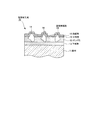
図1に示すように、S45CやS25C等の炭素鋼等からなる基材11上には、Niめっきからなる下地層12(厚さ:約0.5〜5μm)が設けられている。この下地層12上には、Ni系めっきからなるボンド層13が設けられている。このボンド層13には、ダイヤモンドやcBN等からなる超硬質砥粒14(平均粒径:約50〜300μm)が先端側を露出(約30〜40%)させるように植設されている。そして、上記ボンド層13及び上記超硬質砥粒14上には、当該ボンド層13及び当該超硬質砥粒14を覆うようにして中間層15(約0.1〜0.5μm)が設けられている。この中間層15上には、保護層16(約0.1〜2.0μm)が設けられている。
As shown in FIG. 1, a base layer 12 (thickness: about 0.5 to 5 μm) made of Ni plating is provided on a
前記ボンド層13(Hv150〜550程度)は、前記超硬質砥粒14を前記基材11に対して固定するために設けられるものであって、電気Niめっきや無電解Ni−Pめっきや無電解Ni−Bめっき等のようなめっき法によって形成されるNi系めっき層であるが、「ワット浴」(硫酸ニッケルと塩化ニッケルとホウ酸との水溶液)や「スルファミン酸ニッケル浴」(スルファミン酸ニッケルとホウ酸との水溶液)を用いた電気めっきによって形成されるめっき層であると、厚い厚さでも比較的短時間で効率よく形成できると共に、内部に加わる応力を小さくすることができるため、非常に好ましい。
The bond layer 13 (about Hv 150 to 550) is provided to fix the superhard
前記下地層12は、前記基材11と前記ボンド層13との密着性を高めるために設けられるものであって、当該密着性を高める材質であれば特に限定されるものではないが、「ウッド浴」(塩化ニッケルと塩酸との水溶液)を用いた電気めっきによって形成されるNiめっき層であると、電解の際に基材11の表面に多量に発生する水素ガスにより当該基材11の表面が還元雰囲気となって、当該基材11の表面の酸化物が還元されながら当該基材11の表面に形成されることから、当該基材11の表面との密着性が高くなって、非常に好ましい。
The
前記保護層16は、前記ボンド層13よりも高い硬度(Hv1000以上)を有するものであって、ダイヤモンドライクカーボン(Diamond Like Carbon:DLC)等の硬質炭素材料からなり、ダイヤモンド構造(立方晶)とグラファイト構造(六方晶)との中間的な結晶構造を有する、すなわち、炭素を主成分として水素を若干含みながらダイヤモンド結合(SP3結合)とグラファイト結合(SP2結合)との両結合を有するアモルファス構造を有している。このような保護層16は、スパッタリング法、プラズマCVD法、イオン化蒸着法等によって容易に形成することができる。このとき、内部の水素濃度をできるだけ低くすると(少なくとも20原子%以下)、硬度をさらに高くすることができ、SiやCrやTi等の金属成分を含有させると(約1〜5原子%)、内部の応力を緩和して、剥離性を大きく低下させることができるので、非常に好ましい。
The
前記中間層15は、前記ボンド層13よりも高い硬度(Hv700以上)を有すると共に前記保護層よりも高い靱性を有するものであって、Cr及びTiの少なくとも一方の金属、又は、当該金属の窒化物、炭化物、炭窒化物のうちの少なくとも一つの化合物からなり、スパッタリング法、プラズマCVD法、イオン化蒸着法等によって、CrやTiの金属の蒸着層(Hv約700)や、これら金属の窒化物や炭化物や炭窒化物の蒸着層(Hv1500以上)として設けることができる。
The
つまり、本実施形態に係る超砥粒工具10は、めっき法により超硬質砥粒12をNi系のボンド層13で固着した超砥粒工具10において、前記ボンド層13及び前記超硬質砥粒12の表面を覆うように設けられて当該ボンド層13よりも高い硬度を有する保護層16と、前記ボンド層13及び前記超硬質砥粒12と前記保護層16との間に設けられて当該ボンド層13よりも高い硬度を有すると共に当該保護層16よりも高い靱性を有する中間層15と、前記ボンド層13の下方に設けられた下地層12とを備えているのである。
That is, the
このような本実施形態に係る超砥粒工具10の製造方法を次に説明する。
Next, a method for manufacturing the
まず、前処理工程として、基材11において超硬質砥粒14を設ける必要のない箇所にマスキング剤を塗布して乾燥させたら、アルカリ水溶液中に浸漬して脱脂処理した後に水洗し、塩酸水溶液中に浸漬処理して活性化処理した後に水洗する。
First, as a pretreatment step, when a masking agent is applied to a portion of the
次に、上記基材11を「ウッド浴」(塩化ニッケルと塩酸との水溶液)中(pH1.5以下)で電気めっきしてNiめっき層の下地層12を形成した後に水洗したら、当該基材11を「ワット浴」(硫酸ニッケルと塩化ニッケルとホウ酸との水溶液)中(pH4.5)で超硬質砥粒14と共に電気めっきしてNi系めっき層のボンド層13を介して超硬質砥粒14の先端側を露出させるように当該超硬質砥粒14を基材11の所定箇所に固着させた後に水洗し、乾燥させる。
Next, the
続いて、上記基材11に対してスパッタリング法等によりCr等をターゲットにしてCrN等の中間層15を前記ボンド層13及び前記超硬質砥粒12の表面に形成した後、当該基材11に対してスパッタリング法等によりグラファイト等をターゲットにしてダイヤモンドライクカーボン等の保護層16を上記中間層15の表面に形成することにより、超砥粒工具10を得ることができる。
Subsequently, an
このような本実施形態に係る超砥粒工具10においては、ボンド層13よりも高い硬度(Hv1000以上)を有する保護層16を当該ボンド層13の表面を覆うように設けたことから、研削加工等の際に発生した切屑と保護層16とが接触しても、当該保護層16が高耐摩耗性を有して非常に摩耗しにくいので、ボンド層13から超硬質砥粒12が脱落してしまうことを大幅に抑制できると共に、研削加工等のときに炭素鋼からなる被研削体と保護層16とが接触しても、当該被研削体に焼き付きを生じることがないので、当該被研削体の表面粗さが粗くなってしまうことを防止できる。
In the
したがって、本実施形態に係る超砥粒工具10によれば、長寿命化を図ることができると共に被研削体の品質低下を防止することができる。
Therefore, according to the
また、ボンド層13よりも高い硬度(Hv700以上)を有すると共に保護層16よりも高い靱性を有する中間層15を当該ボンド層13と当該保護層16との間に設けたことから、当該保護層16の割れや剥離を大幅に防止することができる。
Further, since the
なぜなら、ダイヤモンドライクカーボンからなる保護層16は、硬度が高くて脆く、Ni系めっき層からなるボンド層13は、硬度が低くて軟らかいことから、研削加工等の際に応力が加わって、ボンド層13に歪を生じてしまうと、当該歪に保護層16が追従できずに割れや剥離を生じてしまう可能性があるものの、上記中間層15を設けることにより、研削加工等の際に応力が加わっても、当該中間層15がバッファとなって、上記保護層16の割れや剥離が防止されるようになるからである。
This is because the
[他の実施形態]
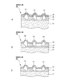
なお、前述した実施形態においては、スパッタリング法等により前記中間層15をボンド層13と保護層16との間及び保護層16と超硬質砥粒14との間に設けた超砥粒工具10の場合について説明したが、他の実施形態として、例えば、図2に示すように、めっき法を適用して、Crめっき層の中間層25を、保護層16と超硬質砥粒14との間に設けることなく、ボンド層13と保護層16との間のみに設けた超砥粒工具20であっても、前述した実施形態の場合と同様な作用効果を得ることができる。
[Other Embodiments]
In the above-described embodiment, the
また、前述した実施形態においては、下地層12及び中間層15,25を設けた超砥粒工具10,20の場合について説明したが、他の実施形態として、例えば、研削条件等の各種条件によっては、図3に示すように、下地層12を省略した超砥粒工具30(図3A参照)や、中間層15,25を省略した超砥粒工具40(図3B参照)や、下地層12及び中間層15,25を省略した超砥粒工具50(図3C参照)を適用することも可能である。
In the above-described embodiment, the case of the
また、前述した実施形態においては、超硬質砥粒14の先端側の表面にも保護層16が設けられている場合について説明したが、本発明はこれに限らず、少なくともボンド層の表面を覆うように保護層が設けられていれば、前述した実施形態の場合と同様な作用効果を得ることができる。
In the embodiment described above, the case where the
本発明に係る超砥粒工具は、長寿命化を図ることができると共に被研削体の品質低下を防止することができるので、金属加工産業等において、極めて有益に利用することができる。 Since the superabrasive tool according to the present invention can extend the life and prevent the quality of the object to be ground from being deteriorated, it can be used extremely beneficially in the metalworking industry and the like.
10,20,30,40,50 超砥粒工具
11 基材
12 下地層
13 ボンド層
14 超硬質砥粒
15,25 中間層
16 保護層
10, 20, 30, 40, 50
Claims (7)
少なくとも前記ボンド層の表面を覆うように設けられて当該ボンド層よりも高い硬度を有する保護層を備えている
ことを特徴とする超砥粒工具。 In superabrasive tools in which super hard abrasive grains are fixed with a Ni-based bond layer by plating,
A superabrasive tool comprising a protective layer provided to cover at least the surface of the bond layer and having a hardness higher than that of the bond layer.
前記保護層が、前記超硬質砥粒も覆うように設けられている
ことを特徴とする超砥粒工具。 The superabrasive tool according to claim 1,
The superabrasive tool, wherein the protective layer is provided so as to cover the superhard abrasive grains.
前記保護層が、ダイヤモンドライクカーボンである
ことを特徴とする超砥粒工具。 In the superabrasive tool according to claim 1 or 2,
The superabrasive tool, wherein the protective layer is diamond-like carbon.
少なくとも前記ボンド層と前記保護層との間に設けられて当該ボンド層よりも高い硬度を有すると共に当該保護層よりも高い靱性を有する中間層を備えている
ことを特徴とする超砥粒工具。 In the superabrasive tool according to any one of claims 1 to 3,
A superabrasive tool comprising an intermediate layer provided between at least the bond layer and the protective layer and having a hardness higher than that of the bond layer and higher toughness than the protective layer.
前記中間層が、前記超硬質砥粒を覆うように設けられた前記保護層と当該超硬質砥粒との間にも設けられている
ことを特徴とする超砥粒工具。 In the superabrasive tool according to claim 4,
A superabrasive tool, wherein the intermediate layer is also provided between the protective layer provided to cover the superhard abrasive grains and the superhard abrasive grains.
前記中間層が、Cr及びTiの少なくとも一方の金属、又は、当該金属の窒化物、炭化物、炭窒化物のうちの少なくとも一つの化合物からなる
ことを特徴とする超砥粒工具。 In the superabrasive tool according to claim 4 or 5,
The intermediate layer is made of at least one of Cr and Ti, or at least one compound of nitride, carbide and carbonitride of the metal.
前記ボンド層の下方に下地層を備えている
ことを特徴とする超砥粒工具。 In the superabrasive tool according to any one of claims 1 to 6,
A superabrasive tool comprising a base layer below the bond layer.
Priority Applications (1)
| Application Number | Priority Date | Filing Date | Title |
|---|---|---|---|
| JP2008259226A JP5285381B2 (en) | 2008-10-06 | 2008-10-06 | Super abrasive tool |
Applications Claiming Priority (1)
| Application Number | Priority Date | Filing Date | Title |
|---|---|---|---|
| JP2008259226A JP5285381B2 (en) | 2008-10-06 | 2008-10-06 | Super abrasive tool |
Publications (2)
| Publication Number | Publication Date |
|---|---|
| JP2010089177A true JP2010089177A (en) | 2010-04-22 |
| JP5285381B2 JP5285381B2 (en) | 2013-09-11 |
Family
ID=42252396
Family Applications (1)
| Application Number | Title | Priority Date | Filing Date |
|---|---|---|---|
| JP2008259226A Expired - Fee Related JP5285381B2 (en) | 2008-10-06 | 2008-10-06 | Super abrasive tool |
Country Status (1)
| Country | Link |
|---|---|
| JP (1) | JP5285381B2 (en) |
Cited By (3)
| Publication number | Priority date | Publication date | Assignee | Title |
|---|---|---|---|---|
| KR101920564B1 (en) | 2017-07-03 | 2018-11-20 | 김성규 | Method of manufacturing a cutting tool |
| CN113001418A (en) * | 2021-01-28 | 2021-06-22 | 广东朗旗新材料科技有限公司 | Ceramic bond of superhard abrasive tool, superhard abrasive tool and preparation method thereof |
| CN114905419A (en) * | 2022-03-24 | 2022-08-16 | 长沙中海瑞超硬材料技术有限公司 | Cutting blade with protective layer, preparation method thereof and excircle cutting machine |
Families Citing this family (1)
| Publication number | Priority date | Publication date | Assignee | Title |
|---|---|---|---|---|
| TWI772171B (en) * | 2021-09-08 | 2022-07-21 | 明志科技大學 | Protective film and protective film stack for chemical mechanical polishing pad dressers |
Citations (6)
| Publication number | Priority date | Publication date | Assignee | Title |
|---|---|---|---|---|
| JP2001210613A (en) * | 2000-01-27 | 2001-08-03 | Allied Material Corp | Pad conditioner for cmp |
| JP2006305661A (en) * | 2005-04-27 | 2006-11-09 | Nagaoka Univ Of Technology | Ultrasonic vibration processing device, and method for manufacturing electrodeposition tool used for ultrasonic vibration processing device |
| JP2007044823A (en) * | 2005-08-10 | 2007-02-22 | Soken:Kk | Cmp pad conditioner in semiconductor planarization cmp process (chemical-mechanical polishing) |
| JP2008515238A (en) * | 2004-09-29 | 2008-05-08 | チエン−ミン・ソン | Molded CMP pad dresser and related methods |
| JP2008155301A (en) * | 2006-12-21 | 2008-07-10 | Ihi Corp | Grinding wheel |
| JP2008155362A (en) * | 2006-12-01 | 2008-07-10 | Shinshu Univ | Electrodeposited diamond tool and manufacturing method for the same |
-
2008
- 2008-10-06 JP JP2008259226A patent/JP5285381B2/en not_active Expired - Fee Related
Patent Citations (6)
| Publication number | Priority date | Publication date | Assignee | Title |
|---|---|---|---|---|
| JP2001210613A (en) * | 2000-01-27 | 2001-08-03 | Allied Material Corp | Pad conditioner for cmp |
| JP2008515238A (en) * | 2004-09-29 | 2008-05-08 | チエン−ミン・ソン | Molded CMP pad dresser and related methods |
| JP2006305661A (en) * | 2005-04-27 | 2006-11-09 | Nagaoka Univ Of Technology | Ultrasonic vibration processing device, and method for manufacturing electrodeposition tool used for ultrasonic vibration processing device |
| JP2007044823A (en) * | 2005-08-10 | 2007-02-22 | Soken:Kk | Cmp pad conditioner in semiconductor planarization cmp process (chemical-mechanical polishing) |
| JP2008155362A (en) * | 2006-12-01 | 2008-07-10 | Shinshu Univ | Electrodeposited diamond tool and manufacturing method for the same |
| JP2008155301A (en) * | 2006-12-21 | 2008-07-10 | Ihi Corp | Grinding wheel |
Cited By (5)
| Publication number | Priority date | Publication date | Assignee | Title |
|---|---|---|---|---|
| KR101920564B1 (en) | 2017-07-03 | 2018-11-20 | 김성규 | Method of manufacturing a cutting tool |
| CN113001418A (en) * | 2021-01-28 | 2021-06-22 | 广东朗旗新材料科技有限公司 | Ceramic bond of superhard abrasive tool, superhard abrasive tool and preparation method thereof |
| CN113001418B (en) * | 2021-01-28 | 2024-01-26 | 广东朗旗新材料科技有限公司 | Ceramic bond of superhard abrasive tool, superhard abrasive tool and preparation method of superhard abrasive tool |
| CN114905419A (en) * | 2022-03-24 | 2022-08-16 | 长沙中海瑞超硬材料技术有限公司 | Cutting blade with protective layer, preparation method thereof and excircle cutting machine |
| CN114905419B (en) * | 2022-03-24 | 2024-03-19 | 长沙中海瑞超硬材料技术有限公司 | Cutting sheet with protective layer and preparation method thereof |
Also Published As
| Publication number | Publication date |
|---|---|
| JP5285381B2 (en) | 2013-09-11 |
Similar Documents
| Publication | Publication Date | Title |
|---|---|---|
| JP4139810B2 (en) | Electrodeposition wire tool | |
| US9371576B2 (en) | Coated tool and methods of making and using the coated tool | |
| JP5999362B2 (en) | Surface coated cutting tool | |
| JPH06114739A (en) | Electrodeposition grinding wheel | |
| JP4293370B2 (en) | Valve lifter | |
| KR20000017533A (en) | Saw wire | |
| TW201136688A (en) | Wire saw and method for fabricating the same | |
| JP2009066689A (en) | Fixed abrasive grain wire saw | |
| JP5285381B2 (en) | Super abrasive tool | |
| JPWO2008026700A1 (en) | Cutting tool, manufacturing method thereof and cutting method | |
| JP2016519002A (en) | Grinding sawing wire and its manufacturing method and use | |
| JP4400677B2 (en) | Thin blade whetstone | |
| JP5839289B2 (en) | Surface coated cutting tool | |
| US20130164557A1 (en) | Coated body and a process for coating a body | |
| US20090226715A1 (en) | Coated article and method of making the same | |
| JPH11226805A (en) | Cutting tool made of coated cemented carbide | |
| JP2009196057A (en) | Thin-bladed whetstone and its manufacturing method | |
| JP5123628B2 (en) | Electrodeposition tool manufacturing method | |
| JPH0760521A (en) | Diamond-coated drill and manufacture thereof | |
| JP3643639B2 (en) | Cemented carbide structure, manufacturing method thereof and cutting tool using the same | |
| JP2009196043A (en) | Electro-deposition tool | |
| JP7169495B2 (en) | Cutting tool coated with electrodeposited abrasive grain layer and method for recycling said cutting tool | |
| KR20120003197A (en) | Diamond tool having strong corrosion- resistance for cmp | |
| CN117359514A (en) | Composite coating diamond abrasive particle cutter and preparation method and application thereof | |
| JP5104394B2 (en) | Thin blade grinding wheel manufacturing method |
Legal Events
| Date | Code | Title | Description |
|---|---|---|---|
| A621 | Written request for application examination |
Free format text: JAPANESE INTERMEDIATE CODE: A621 Effective date: 20110810 |
|
| A131 | Notification of reasons for refusal |
Free format text: JAPANESE INTERMEDIATE CODE: A131 Effective date: 20130305 |
|
| A521 | Written amendment |
Free format text: JAPANESE INTERMEDIATE CODE: A523 Effective date: 20130412 |
|
| TRDD | Decision of grant or rejection written | ||
| A01 | Written decision to grant a patent or to grant a registration (utility model) |
Free format text: JAPANESE INTERMEDIATE CODE: A01 Effective date: 20130507 |
|
| A61 | First payment of annual fees (during grant procedure) |
Free format text: JAPANESE INTERMEDIATE CODE: A61 Effective date: 20130531 |
|
| LAPS | Cancellation because of no payment of annual fees |