JP2010088436A - Site-specific cell perforation technique - Google Patents
Site-specific cell perforation technique Download PDFInfo
- Publication number
- JP2010088436A JP2010088436A JP2009262566A JP2009262566A JP2010088436A JP 2010088436 A JP2010088436 A JP 2010088436A JP 2009262566 A JP2009262566 A JP 2009262566A JP 2009262566 A JP2009262566 A JP 2009262566A JP 2010088436 A JP2010088436 A JP 2010088436A
- Authority
- JP
- Japan
- Prior art keywords
- membrane
- cell
- cells
- reaction
- injection
- Prior art date
- Legal status (The legal status is an assumption and is not a legal conclusion. Google has not performed a legal analysis and makes no representation as to the accuracy of the status listed.)
- Granted
Links
Images


Classifications
-
- C—CHEMISTRY; METALLURGY
- C12—BIOCHEMISTRY; BEER; SPIRITS; WINE; VINEGAR; MICROBIOLOGY; ENZYMOLOGY; MUTATION OR GENETIC ENGINEERING
- C12N—MICROORGANISMS OR ENZYMES; COMPOSITIONS THEREOF; PROPAGATING, PRESERVING, OR MAINTAINING MICROORGANISMS; MUTATION OR GENETIC ENGINEERING; CULTURE MEDIA
- C12N15/00—Mutation or genetic engineering; DNA or RNA concerning genetic engineering, vectors, e.g. plasmids, or their isolation, preparation or purification; Use of hosts therefor
- C12N15/09—Recombinant DNA-technology
- C12N15/87—Introduction of foreign genetic material using processes not otherwise provided for, e.g. co-transformation
- C12N15/89—Introduction of foreign genetic material using processes not otherwise provided for, e.g. co-transformation using microinjection
-
- C—CHEMISTRY; METALLURGY
- C12—BIOCHEMISTRY; BEER; SPIRITS; WINE; VINEGAR; MICROBIOLOGY; ENZYMOLOGY; MUTATION OR GENETIC ENGINEERING
- C12M—APPARATUS FOR ENZYMOLOGY OR MICROBIOLOGY; APPARATUS FOR CULTURING MICROORGANISMS FOR PRODUCING BIOMASS, FOR GROWING CELLS OR FOR OBTAINING FERMENTATION OR METABOLIC PRODUCTS, i.e. BIOREACTORS OR FERMENTERS
- C12M35/00—Means for application of stress for stimulating the growth of microorganisms or the generation of fermentation or metabolic products; Means for electroporation or cell fusion
-
- C—CHEMISTRY; METALLURGY
- C12—BIOCHEMISTRY; BEER; SPIRITS; WINE; VINEGAR; MICROBIOLOGY; ENZYMOLOGY; MUTATION OR GENETIC ENGINEERING
- C12N—MICROORGANISMS OR ENZYMES; COMPOSITIONS THEREOF; PROPAGATING, PRESERVING, OR MAINTAINING MICROORGANISMS; MUTATION OR GENETIC ENGINEERING; CULTURE MEDIA
- C12N13/00—Treatment of microorganisms or enzymes with electrical or wave energy, e.g. magnetism, sonic waves
Abstract
Description
本発明は、膜変性剤等を用いて細胞膜等の膜を部分的に処理することにより膜を穿孔する方法に関する。また、この方法を用いて作出した孔を持つ細胞等の膜構造体に関する。さらには膜変性効果を有する膜破壊部材に関する。 The present invention relates to a method for perforating a membrane by partially treating a membrane such as a cell membrane with a membrane denaturant or the like. The present invention also relates to a membrane structure such as a cell having pores created by using this method. Furthermore, the present invention relates to a membrane breaking member having a membrane modification effect.
遺伝子治療や、生物を利用した人工的な物質生産系等において、細胞内に核酸や蛋白質等の物質を導入する手法はきわめて重要である。逆に、細胞内から核等の組織を取り出す技術も近年重要視されており、クローン動物の作出等に利用されている。言い換えれば、生物を構成する基本単位である細胞に対して物質を注入したり取り出したりすることは生物工学の基本技術であると言える。
しかしながら、このような物質導入や取り出しの技法として効率的なものは限られている。
In gene therapy and artificial substance production systems using living organisms, techniques for introducing substances such as nucleic acids and proteins into cells are extremely important. On the other hand, techniques for extracting tissues such as nuclei from the inside of cells have also been emphasized in recent years, and are used for the production of cloned animals. In other words, it can be said that injecting and taking out substances from cells, which are basic units constituting a living organism, is a basic technology of biotechnology.
However, there are limited effective techniques for introducing and removing such substances.
従来の物質導入技法を大別すると、
a)不特定の細胞群を対象にした導入手法
b)特定の細胞を対象とした導入手法
の2者に分けられる。
Broadly speaking, conventional substance introduction techniques
a) Introduction method targeting an unspecified cell group b) Introduction method targeting a specific cell can be divided into two groups.
a)の技法としては、ウイルスベクター(レトロウイルスベクター等)を用いた導入法、非ウイルスベクター(リポフェクチン等)を用いた導入法、電気穿孔法、りん酸カルシウム法、パーティクルガン法等を例示することができる。またb)の技法としては、マイクロインジェクション法を例示することが出来る。[ 「遺伝子治療の基礎技術」,羊土社(1995): 非特許文献1] Examples of the technique a) include an introduction method using a viral vector (retroviral vector or the like), an introduction method using a non-viral vector (lipofectin or the like), an electroporation method, a calcium phosphate method, a particle gun method, or the like. be able to. Moreover, as a technique of b), the microinjection method can be illustrated. ["Basic technology of gene therapy", Yodosha (1995): Non-patent document 1]
一般的にb)の技法は、卵細胞のような大型の細胞に対して用いられる場合が多い。この理由のひとつは、マイクロインジェクション法が微細ガラス管の剪断力を用いた細胞膜破壊を利用しているためで、細胞の大きさにより技術的限界が生じてくるものと考えられる。また、本技法は施術者の熟練を要する技法でもあり、自動化は困難である。また卵細胞以外の一般の細胞には細胞膜の柔軟性故にピペットが刺入できない場合も多い。 In general, the technique b) is often used for large cells such as egg cells. One of the reasons is that the microinjection method uses cell membrane destruction using the shearing force of a fine glass tube, and it is considered that a technical limit arises depending on the size of the cell. Also, this technique is a technique that requires the skill of the practitioner and is difficult to automate. In addition, general cells other than egg cells often cannot be inserted due to the flexibility of the cell membrane.
a)の技法は、不特定の細胞群に対して確率的に処理を加え、細胞群の一部が目的となる物質導入が導入されることを期待するものである。したがって、すべての細胞内に目的物質が導入されることは希である。また、目的物質が導入された細胞のみを分離する作業は、一般に困難であることが多い。
また、細胞内の組織を無傷のまま取り出すためには、精巧なマイクロマニピュレータが必要であり、上記のマイクロインジェクション法と同様の問題が存在していた。
The technique of a) expects that the introduction of a substance intended for a part of the cell group will be introduced by randomly processing an unspecified cell group. Therefore, the target substance is rarely introduced into all cells. In general, it is often difficult to separate only cells into which a target substance has been introduced.
Moreover, in order to take out the tissue in the cell intact, an elaborate micromanipulator is required, and the same problem as the above microinjection method exists.
このように、細胞処理が医学・工学において日常的な技術となっている現在、細胞処理の再現性・精度の向上は非常に重要な課題である。例えば、生殖細胞の処理に際しては、卵細胞が体細胞に比較して各個体から非常に少数しか得られない貴重な遺伝資源であることを考慮すると、その処理の成功率が施術者の技量に左右されるという状況は工学的見地から大きな問題である。 As described above, the improvement of reproducibility and accuracy of cell processing is a very important issue now that cell processing has become a routine technique in medicine and engineering. For example, in the treatment of germ cells, considering that egg cells are a valuable genetic resource that can be obtained in very small numbers from each individual compared to somatic cells, the success rate of the treatment depends on the skill of the practitioner. This situation is a big problem from an engineering point of view.
また、上記の処理はいずれも、単細胞、遊走性細胞あるいはガン細胞のような生体からの単離・生体への再導入が可能な細胞に限られていた。したがって、神経細胞のように生体と不可分の細胞への改変処理は極めて困難なものであった。 In addition, all of the above treatments are limited to cells that can be isolated from a living body and reintroduced into the living body, such as single cells, migratory cells, or cancer cells. Therefore, it has been extremely difficult to modify cells that are inseparable from living organisms such as nerve cells.
上記に例示したもの以外にも、細胞の改変による技術発展の可能性はますます大きくなっている。以下に典型的な例を数例示す。
1)クローン生物の作成には卵細胞の膜を介して核または染色体遺伝子を注入する作業が必須であるが、成功率は非常に低い。
2)特定の細胞に磁性体を組み込んだ細胞を作製することができれば、細胞の位置を磁気的に制御することが可能となる。一般的には、磁性細菌由来の磁性体生成遺伝子を導入する手段が用いられており、成功例があるが、医療用途の細胞等においては人工的な磁性体を挿入した方が適する場合も多い。
3)マイクロマシン、例えば細胞レベルの微小手術機械を作製するためには、単なる物理的手段では細胞膜を切開するに足る切削出力が得られないことは容易に想像される。また、単なる化学反応による膜破壊では破壊制御の上で問題がある。
4)神経細胞の活動電位計測・電気刺激において、基礎研究用の電極を除く実用電極はいずれも細胞外での計測・刺激を行っていた。これは本来の神経活動に関わる電位閾値に比較して検出信号の微弱化/刺激入力の増大という、精度の向上を妨げる問題の原因となっていた。神経細胞内に電極を設置可能となれば、神経の本来の電位閾値に同等の計測・刺激が可能となることに加え、電極と神経の情報交換が一対一の精度で行うことが可能となる。
5)エネルギー変換工学分野において、人工光合成を目指し光起電力を持つ微小な光電変換素子の人工膜への配置の研究が行われている。これは光電変換素子による起電力を膜間電位発生に利用するものである。このような微小光電変換素子を細胞膜中/ミトコンドリア膜中に配置可能となれば、細胞代謝に必要なエネルギーを光で供給することが可能になる。すなわち、様々な細胞に植物のような光エネルギー利用能力を付加することが可能になるものと考えられる。
In addition to those exemplified above, the possibility of technological development by cell modification is increasing. Some typical examples are shown below.
1) Although the work of injecting a nuclear or chromosomal gene through the membrane of an egg cell is essential for the creation of a cloned organism, the success rate is very low.
2) If a cell in which a magnetic substance is incorporated into a specific cell can be produced, the position of the cell can be magnetically controlled. In general, means for introducing a magnetic substance-producing gene derived from a magnetic bacterium has been used, and there are successful examples, but it is often appropriate to insert an artificial magnetic substance in cells for medical use etc. .
3) In order to fabricate a micromachine, for example, a micro-surgical machine at the cellular level, it is easily imagined that cutting power sufficient to cut a cell membrane cannot be obtained by simple physical means. In addition, film destruction by simple chemical reaction has a problem in terms of destruction control.
4) In the measurement of the action potential of nerve cells and electrical stimulation, all the practical electrodes except the electrodes for basic research were measured and stimulated outside the cell. This has caused a problem that hinders improvement in accuracy, that is, the detection signal is weakened / stimulation input is increased as compared with the potential threshold value related to the original neural activity. If an electrode can be placed in a nerve cell, measurement and stimulation equivalent to the original potential threshold of the nerve can be performed, and information exchange between the electrode and the nerve can be performed with one-to-one accuracy. .
5) In the field of energy conversion engineering, research is being conducted on the placement of small photoelectric conversion elements with photovoltaic power on artificial membranes for artificial photosynthesis. This utilizes an electromotive force generated by a photoelectric conversion element for generating a transmembrane potential. If such a micro photoelectric conversion element can be arranged in the cell membrane / mitochondrion membrane, it becomes possible to supply energy necessary for cell metabolism with light. That is, it is considered that light energy utilization ability like plants can be added to various cells.
これら細胞処理の根本的な問題点は細胞膜の破壊を制御する技術の不備にある。単に細胞を破壊する用途であれば、種々の毒物が長期にわたって検討されている。しかしながら、細胞死を引き起こすことなく、部分的かつ一時的に細胞膜を破壊するという細胞工学上の要求に応えるものではなかった。また、微細ガラス管等を用いる物理的な剪断力利用した方法には限界があった。すなわち、本発明が解決しようとする課題は物理的剪断力以外の方法で生体膜の破壊を制御しながら穿孔する技術、すなわち膜の破壊制御技術を開発することである。 The fundamental problem with these cell treatments is the lack of technology to control the destruction of the cell membrane. If the application is simply to destroy cells, various poisons have been studied for a long time. However, it did not meet the cell engineering requirement of partially and temporarily destroying the cell membrane without causing cell death. In addition, there is a limit to the method using physical shearing force using a fine glass tube or the like. That is, the problem to be solved by the present invention is to develop a technique for perforating while controlling the destruction of the biological membrane by a method other than the physical shearing force, that is, a technique for controlling the destruction of the membrane.
膜破壊技術は前述の通り様々なものがあるが、部位特異的に破壊させる技術は限られていた。マイクロインジェクション装置やマイクロマニピュレーターは部位特異的な膜破壊を伴う装置であるが、膜破壊や穿孔は、物理的剪断力に依存していた。すなわち、本発明が解決しようとするもうひとつの課題は物理的剪断力以外の方法で生体膜の破壊を制御しながら穿孔するための部材を作出することである。 There are various film destruction techniques as described above, but the techniques for site-specific destruction have been limited. Microinjection devices and micromanipulators are devices with site-specific membrane breakage, but membrane breakage and perforation depended on physical shearing force. That is, another problem to be solved by the present invention is to create a member for perforating while controlling the destruction of the biological membrane by a method other than physical shearing force.
生体膜の破壊を制御しながら穿孔するために必要なのは、破壊場所と破壊量の制御である。そこで本発明者らは、膜を対象に、いかなる手法を用いれば膜破壊の活性を制御しつつ膜の変性や穿孔が可能となるかに関して鋭意検討を加えた。 What is necessary for perforating while controlling the destruction of the biological membrane is the control of the location and amount of destruction. Therefore, the present inventors have intensively studied on what kind of technique can be used for the membrane to control the membrane breaking activity and enable the membrane to be modified or perforated.
膜を一時的かつ部分的に変成/破壊する方法としては、リパーゼやプロテアーゼ等を用いる酵素的な破壊、ベータ線やレーザー光を用いる方法等も考えうるが、本発明者らは、物理的剪断以外の方法で細胞膜を破壊するための方法の一例として、リン脂質ラジカル連鎖過酸化反応に着目した。 As a method for temporarily transforming / destructing the membrane temporarily, an enzymatic disruption using lipase or protease, a method using beta rays or laser light, etc. can be considered. As an example of a method for destroying a cell membrane by a method other than the above, attention was paid to a phospholipid radical chain peroxidation reaction.
一重項酸素やスーパーオキシドラジカルといった活性酸素は細胞膜の不飽和リン脂質を連鎖反応で過酸化する。それに対し細胞は膜中のラジカル捕獲剤であるα-tocopherol(ビタミンE)や、水溶性の抗酸化剤であるL-ascorbic acid(ビタミンC)、superoxide dismutase(SOD)等の酸化防衛機構を持ち、酸化に抵 抗する。["Free Radicals in Biology and Medicine", Oxford university Press (1985)]。 Active oxygen, such as singlet oxygen and superoxide radical, peroxidizes unsaturated phospholipids in cell membranes by a chain reaction. On the other hand, cells have oxidation defense mechanisms such as α-tocopherol (vitamin E), a radical scavenger in the membrane, and L-ascorbic acid (vitamin C), superoxide dismutase (SOD), which are water-soluble antioxidants. Resists oxidation. ["Free Radicals in Biology and Medicine", Oxford University Press (1985)].
このような連鎖酸化作用が酸化防衛能を越えると、リン脂質膜破壊は指数関数的に急速に進行し、細胞膜がイオン透過阻止能を失うため、細胞は代謝維持が不可能となる。この連鎖膜破壊が進行すると最終的に細胞は死滅する。 When such a chain oxidation action exceeds the ability to defend against oxidation, phospholipid membrane destruction proceeds exponentially rapidly, and the cell membrane loses the ability to inhibit ion permeation, so that the cells cannot maintain metabolism. When this chain membrane breaks down, the cells eventually die.
光により活性酸素を生成し、このような脂質連鎖過酸化反応のトリガーとなる分子は光増感剤(Photosensitizer,PS)と呼ばれる。一般的な光増感剤としては、ローズベンガル、ポルフィリン等が挙げられる。 Molecules that generate active oxygen by light and trigger such lipid chain peroxidation are called photosensitizers (PS). Common photosensitizers include rose bengal and porphyrin.
このような光増感剤を膜変成剤として使用することで、膜の変成に際しては、目標となる最小限の細胞表面に部分的に短時間連鎖過酸化反応を起こすだけでよいことになり、しかも膜穿孔作業の際に過酸化反応により障害を受けた膜は、穿孔後に膜自身の流動性、また上記の抗酸化系により修復されることが期待される。 By using such a photosensitizer as a membrane modifying agent, it is only necessary to cause a partial chain peroxidation reaction for a short period of time on the target minimum cell surface when modifying the membrane, Moreover, it is expected that a membrane damaged by a peroxidation reaction during membrane perforation work will be repaired by the fluidity of the membrane itself and the above antioxidant system after perforation.
本発明者らは、神経系の培養細胞PC12の表面膜に光増感剤の一種であるターチオフェン(5'5"-bis(aminomethyl)-2,2':5',2"-terthiophene dihydrochloride)を塗布した。光増感剤は光照射により制御可能な膜変成剤である。膜抵抗 の測定により、細胞全体へのレーザー光照射により活性化された光増感剤の作用で、膜抵抗、すなわち膜のイオン透過性が上昇することを解明した。また光量及び光増感剤の量を制御することで、光照射により引き起こされる膜抵抗変化は少なくとも
1) 影響なし
2) 抵抗減少後回復
3) 抵抗消失
の3段階に制御可能であることを明らかにした。
The present inventors have used terthiophene (5'5 "-bis (aminomethyl) -2,2 ': 5', 2" -terthiophene dihydrochloride, a kind of photosensitizer, on the surface membrane of cultured cells PC12 of the nervous system. ) Was applied. The photosensitizer is a film modifier that can be controlled by light irradiation. By measuring the membrane resistance, it was clarified that the membrane resistance, that is, the ion permeability of the membrane, was increased by the action of the photosensitizer activated by laser light irradiation to the whole cell. In addition, by controlling the amount of light and the amount of photosensitizer, the change in film resistance caused by light irradiation is at least 1) No effect 2) Recovery after resistance decrease 3) It is clear that it can be controlled in 3 stages of resistance disappearance I made it.
さらに本発明者らは、特記すべき点として、膜のイオン透過性が破壊前の状態に回復する時間が好適条件下では30秒程度であることを見出した。 Furthermore, the present inventors have found that as a special point, the time required for the ion permeability of the membrane to recover to the state before destruction is about 30 seconds under suitable conditions.
また、レーザー光により細胞の軸索部のみに光照射を行った場合も同様の膜抵抗変化が観測された。 Similar changes in membrane resistance were also observed when only the axon portion of the cell was irradiated with laser light.
さらに本発明者らは光増感剤を利用した細胞膜変成を、細胞への物質導入に応用可能であるか検討を行うため、マイクロインジェクション処理への適用を試みた。マイクロインジェクション処理に際しては水溶性蛍光染色試薬Lucifer Yellow CH(LY)を含むインジェクション液を調整し、LYをPC12細胞に注入可能であることをインジェクション成功の判定指標とした。また電動マニピュレーターによりインジェクション処理を自動化し、成功確率評価に及ぼす人為的な影響を極力排除した。 Furthermore, the present inventors tried to apply to microinjection treatment in order to investigate whether cell membrane modification using a photosensitizer can be applied to substance introduction into cells. In the microinjection treatment, an injection solution containing a water-soluble fluorescent staining reagent Lucifer Yellow CH (LY) was prepared, and the ability to inject LY into PC12 cells was used as a determination index for successful injection. In addition, the injection process was automated by an electric manipulator to eliminate as much as possible the artificial influence on the success probability evaluation.
このようなインジェクション処理系において、インジェクション液中の光増感剤ターチオフェン(5'5"-bis(aminomethyl)-2,2':5',2"-terthiophene dihydrochloride)100 μMの有無、および100W水銀ランプによる2分間の光照射処理の有無により、インジェクション成功確率がどのように変化するか測定を行った。 In such an injection treatment system, the presence of the photosensitizer terthiophene (5'5 "-bis (aminomethyl) -2,2 ': 5', 2" -terthiophene dihydrochloride) 100 μM in the injection solution and 100 W We measured how the success rate of injection changes depending on whether or not the mercury lamp was irradiated for 2 minutes.
その結果、光増感剤含有インジェクション液を使用し光照射を実施した場合はインジェクション成功確率は約80%であった。その他対照例では同約0〜10%であった。このように膜変性を利用することにより、顕著なインジェクション成功率の改善が認められた。 As a result, when the photosensitizer-containing injection solution was used for light irradiation, the injection success probability was about 80%. In other control examples, it was about 0 to 10%. Thus, the remarkable improvement of the injection success rate was recognized by utilizing membrane modification | denaturation.
更にインジェクション処理後の細胞のLY保持率を細胞生存率の指標として、光増感処理と通常処理の間での細胞生存率の比較を行った。光増感処理を行った細胞は3日〜6日生存率が約90%と、通常処理による同生存率が10%程度であった場合に比較して有為に高かった。 Furthermore, the cell viability between the photosensitization treatment and the normal treatment was compared using the LY retention rate of the cells after the injection treatment as an index of cell viability. Cells subjected to the photosensitization treatment had a survival rate of about 90% at 3 to 6 days, which was significantly higher than that when the survival rate by the normal treatment was about 10%.
これらの結果はすなわち、物理的剪断力によるインジェクション技術に対し、細胞に及ぼす傷害を抑える手段として、膜変性を利用することの技術上の優位を明白に示すものである。 These results clearly show the technical advantage of utilizing membrane denaturation as a means of suppressing injury to cells over injection techniques based on physical shear forces.
以上のことより、光増感剤と光との組み合わせを用いることによって、膜の好適な穿孔を実施しうることが示された。すなわち膜破壊の程度によって、細胞が死滅せずに膜が修復される条件を容易に見出しうるのである。当然、光増感材等の膜破壊材を支持体に塗布した膜破壊部材を作製し、この膜破壊部材と膜とを接触させることは容易に実施可能なことは言うまでもない。 From the above, it has been shown that suitable perforation of the film can be carried out by using a combination of a photosensitizer and light. In other words, depending on the degree of membrane destruction, it is possible to easily find a condition for repairing the membrane without killing the cells. Of course, it is needless to say that a film-breaking member in which a film-breaking material such as a photosensitizer is applied to a support is produced and the film-breaking member and the film are brought into contact with each other.
例えば、膜変成剤を塗布したマイクロビーズを一例とする浮遊する膜破壊部材を利用し、レーザーピンセット等による操作によりこの膜破壊部材を細胞に接触させることも可能である。さらにはこのような接触状態において膜変成反応を開始させ、細胞内にこの膜破壊部材を入れることが可能である。膜変成剤自体がミセル等の膜構造体そのものであってもよい。 For example, it is also possible to use a floating membrane disrupting member such as a microbead coated with a membrane modifying agent, and bring this membrane disrupting member into contact with a cell by an operation using laser tweezers or the like. Furthermore, it is possible to start the membrane denaturation reaction in such a contact state and put the membrane-breaking member into the cell. The membrane modifying agent itself may be a membrane structure itself such as a micelle.
さらに本発明者らは、原子間力顕微鏡の走査プローブを電極化し、さらに光増感剤 5'5"-bis(aminomethyl)-2,2':5',2"-terthiophene dihydrochlorideをその探針部に塗布した新しい部材を作製した。この光増感剤を塗布された部材が細胞膜内に挿入された場合には、膜内外の電極の間に細胞膜に起因する抵抗が観測される。原子間力顕微鏡の電極そのものが有する物理的剪断力のみでは細胞穿孔に足るだけの強度を有していないことから、新たに作製されたこの部材は、原子間力顕微鏡の電極機能と制御的膜破壊機能の両者を兼ね備えた部材として利用しうることを示した。既存の数多くの部材に光増感化合物等の塗布または固定を行うことにより、従来の機能に加えて制御的膜破壊機能を付与することも容易に行い得る。 Furthermore, the present inventors made an atomic force microscope scanning probe into an electrode, and further used a photosensitizer 5'5 "-bis (aminomethyl) -2,2 ': 5', 2" -terthiophene dihydrochloride as its probe. A new member applied to the part was prepared. When a member coated with this photosensitizer is inserted into a cell membrane, resistance due to the cell membrane is observed between the electrodes inside and outside the membrane. Since the physical shearing force of the atomic force microscope electrode itself does not have sufficient strength for cell perforation, this newly created member is used for the electrode function and control membrane of the atomic force microscope. It was shown that it can be used as a member having both destruction functions. By applying or fixing a photosensitizing compound or the like to a number of existing members, it is possible to easily impart a controlled film breaking function in addition to the conventional function.
すなわち、本発明は以下のものを含む。
(1) 特定の刺激により膜変性反応が誘起される特定の化合物を含む薬剤を膜の一部または全部に接触させた後、該刺激を与えることにより該膜の特定の部位を変性または穿孔する方法。
(2)膜が細胞膜、細胞壁、生体膜または人工膜であることを特徴とする(1)に記載の方法。
(3)刺激を与える領域が薬剤を接触させる領域に含まれることを特徴とする(1)または(2)のいずれかに記載の方法。
(4)薬剤を接触させる領域が刺激を与える領域に含まれることを特徴とする(1)または(2)のいずれかに記載の方法。
(5)薬剤が支持体を用いて接触せしめられることを特徴とする(4)に記載の方法。
(6)特定の刺激が光であり、化合物が光増感化合物であることを特徴とする(1)〜(5)のいずれかに記載の方法。
(7)(1)〜(6)のいずれかの方法を用いて得られる、特定の部位が変性または穿孔された膜または該膜を含む膜構造体。
(8)膜が細胞膜、生体膜または人工膜であることを特徴とする(7)に記載の膜または該膜を含む膜構造体。
(9)膜構造体が細胞、ミセルまたはリポソームであることを特徴とする(7)または(8)のいずれかに記載の膜構造体。
(10)注入を目的とする化合物を含む薬剤とキャリアーとからなる複合体と、(7)〜(9)のいずれかに記載の構造体とを混合することにより構造体内部に該化合物を注入する方法。
(11)キャリアーが液体または固体であることを特徴とする(10)に記載の方法。
(12)物質が核酸または蛋白質であることを特徴とする(10)または(11)のいずれかに記載の方法。
(13)支持体と、この支持体の表面の少なくとも一部に形成した、物理的剪断力以外の膜変性力を有する膜変性反応促進部位とを含む、膜の特定の部位を変性または穿孔することを目的とする膜破壊部材。
(14)支持体が棒状、管状、針状、または球状であることを特徴とする(13)に記載の膜破壊部材。
(15)膜変性反応促進部位に膜変性反応を生じせしめる化合物が塗布または固定されていることを特徴とする(13)または(14)のいずれかに記載の膜破壊部材。
(16)膜変性反応が活性酸素種の直接・間接的な生成反応により開始される膜成分の連鎖的な過酸化反応を利用するものであることを特徴とする、(15)に記載の膜破壊部材。
(17)膜変性反応が、特定の刺激および反応前駆物質により誘起され膜の変性または破壊を生じせしめる反応を含む反応であることを特徴とする(15)または(16)のいずれかに記載の膜破壊部材。
(18)特定の刺激が光で、反応前駆物質が光増感化合物であることを特徴とする(17)に記載の膜破壊部材。
(19)膜の変性または破壊後、支持体が該膜を貫通し、貫通した該膜が該支持体と密着して接触することを特徴とする(13)〜(18)のいずれかに記載の膜破壊部材。
(20)膜が細胞膜、生体膜または人工膜であることを特徴とする(13)〜(19)のいずれかに記載の膜破壊部材。
That is, the present invention includes the following.
(1) A drug containing a specific compound that induces a membrane denaturation reaction by a specific stimulus is brought into contact with a part or all of the membrane, and then the specific site of the membrane is denatured or perforated by applying the stimulus. Method.
(2) The method according to (1), wherein the membrane is a cell membrane, a cell wall, a biological membrane or an artificial membrane.
(3) The method according to any one of (1) and (2), wherein a region to which stimulation is applied is included in a region in which a drug is contacted.
(4) The method according to any one of (1) and (2), wherein the region to be contacted with the drug is included in the region to be stimulated.
(5) The method according to (4), wherein the drug is contacted using a support.
(6) The method according to any one of (1) to (5), wherein the specific stimulus is light and the compound is a photosensitizing compound.
(7) A membrane obtained by using the method according to any one of (1) to (6), wherein a specific site is denatured or perforated, or a membrane structure including the membrane.
(8) The membrane according to (7) or the membrane structure including the membrane, wherein the membrane is a cell membrane, a biological membrane or an artificial membrane.
(9) The membrane structure according to any one of (7) and (8), wherein the membrane structure is a cell, micelle or liposome.
(10) Injecting the compound into the structure by mixing a complex comprising a drug containing a compound intended for injection and a carrier and the structure according to any one of (7) to (9) how to.
(11) The method according to (10), wherein the carrier is liquid or solid.
(12) The method according to any one of (10) and (11), wherein the substance is a nucleic acid or a protein.
(13) Denature or perforate a specific portion of the membrane including the support and a membrane modification reaction promoting site having a membrane modification force other than a physical shear force formed on at least a part of the surface of the support. A membrane-breaking member intended for this purpose.
(14) The membrane-breaking member according to (13), wherein the support is rod-shaped, tubular, needle-shaped, or spherical.
(15) The film-breaking member according to any one of (13) and (14), wherein a compound that causes a film-denaturing reaction is applied or fixed at a site that promotes the film-denaturing reaction.
(16) The membrane according to (15), wherein the membrane denaturation reaction utilizes a chain peroxidation reaction of membrane components initiated by a direct / indirect generation reaction of active oxygen species. Destructive member.
(17) The membrane denaturing reaction is a reaction including a reaction that is induced by a specific stimulus and a reaction precursor to cause denaturation or destruction of the membrane. (15) or (16) Film breaking member.
(18) The film-disrupting member according to (17), wherein the specific stimulus is light and the reaction precursor is a photosensitizing compound.
(19) The structure according to any one of (13) to (18), wherein the support penetrates through the membrane after the denaturation or destruction of the membrane, and the penetrated membrane comes into close contact with the support. Film breaker.
(20) The membrane breaking member according to any one of (13) to (19), wherein the membrane is a cell membrane, a biological membrane or an artificial membrane.
膜を変性または穿孔するために用いられる化合物と刺激との組み合わせとしては、膜が完全に破壊されるのではなく、制御可能な状態で穿孔することが可能なものであれば、いかなる組み合わせを用いても構わない。用いうる刺激としては光を含む電磁波、放射線を含む粒子線、加熱、冷却、電気、磁気、超音波を含む振動、物理接触、化学物質の他、細胞を含む生物全般、ウイルス等を例示することができる。またこれらの刺激は単一の刺激として用いても構わないし、併用しても構わない。 Any combination of compounds and stimuli used to denature or perforate the membrane can be used as long as the membrane is not completely destroyed and can be perforated in a controlled manner. It doesn't matter. Examples of stimuli that can be used include electromagnetic waves including light, particle beams including radiation, heating, cooling, electricity, magnetism, vibration including ultrasound, physical contact, chemical substances, organisms including cells, viruses, etc. Can do. These stimuli may be used as a single stimulus or in combination.
膜を変性または穿孔するために用いられる化合物としては、膜変性や膜破壊に関与する酵素、抗体分子、膜結合蛋白質、糖脂質、脂質等を用いることも可能であるし、光増感剤であるポルフィリン、ローズベンガル、メチレンブルー、アシッドレッド、αターチエニル等及びそれらの誘導体を用いることもできる。また、活性酸素種等の酸化剤、還元剤、ニトログリセリン・ピクリン酸等爆発性化合物、磁性微粒子・磁性流体、金属粒子・半導体粒子・絶縁体粒子・光電変換素子・圧電素子等も適宜用い得る。またこれらの化合物は単独に用いられても構わないし、併用して用いられても構わない。 As a compound used for denaturing or perforating the membrane, an enzyme, an antibody molecule, a membrane-bound protein, a glycolipid, a lipid, etc. involved in membrane denaturation or membrane disruption can be used. Certain porphyrins, rose bengal, methylene blue, acid red, α-tertienyl, etc. and their derivatives can also be used. In addition, oxidizing agents such as active oxygen species, reducing agents, explosive compounds such as nitroglycerin and picric acid, magnetic fine particles / magnetic fluid, metal particles / semiconductor particles / insulator particles / photoelectric conversion elements / piezoelectric elements, etc. can be used as appropriate. . These compounds may be used alone or in combination.
変性や穿孔を目的とする膜は、光電変換素子や圧電素子を含む膜であってもよいし、動植物の細胞膜や細胞壁、生体膜、あるいは人工膜であっても構わない。生体膜としては、細胞壁を含む細胞外皮、細胞膜を含む細胞内膜、核膜、ウイルス膜、細胞質微小管、ミクロゾーム膜、ゴルジ装置膜、リソゾーム膜、膜胞体膜、液胞膜、ペルオキシゾーム膜、プラズチド膜、リボソーム膜、ミトコンドリア膜等を例示することができ、またこれらを組み合わせて再構成した膜であってもよい。人工膜としては、タンパク質膜、脂質膜、コラーゲン等高分子膜、金属膜、半導体膜、絶縁体膜、ポリアセチレン・ポリチオフェン等導電性高分子膜等を例示することができる。 The film intended for denaturation or perforation may be a film containing a photoelectric conversion element or a piezoelectric element, or may be a cell membrane, cell wall, biological membrane, or artificial membrane of animals or plants. Biological membranes include cell envelopes including cell walls, intracellular membranes including cell membranes, nuclear membranes, virus membranes, cytoplasmic microtubules, microsomal membranes, Golgi apparatus membranes, lysosomal membranes, membrane endoplasmic reticulum membranes, vacuolar membranes, peroxisome membranes, A plastid membrane, a ribosome membrane, a mitochondrial membrane and the like can be exemplified, and a membrane reconstructed by combining these may be used. Examples of the artificial membrane include protein membranes, lipid membranes, polymer membranes such as collagen, metal membranes, semiconductor membranes, insulator membranes, and conductive polymer membranes such as polyacetylene and polythiophene.
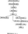
膜破壊の方法としては、第一に、細胞膜に化合物を接触させ、接触領域の一部を刺激処理することにより化合物が膜に接触した領域より小さい範囲のみに変性/破壊を生じさせる方法を提供しうる。例えば、水溶性の光増感化合物溶液で処理した細胞に対し、微細スリットを通した光を照射することにより、照射を受けた部分の細胞膜のみを破壊、穿孔することが可能である。 As a method of membrane destruction, firstly, a method is provided in which a compound is brought into contact with a cell membrane and a part of the contact area is subjected to a stimulation treatment so that the compound is denatured / destructed only in an area smaller than the area in contact with the membrane. Yes. For example, by irradiating a cell treated with a water-soluble photosensitizing compound solution with light through a fine slit, it is possible to destroy and perforate only the cell membrane of the irradiated part.
第二に、細胞膜の一部に化合物を接触させ、それよりも大きい領域を刺激処理することにより、化合物が接触した領域のみに変性/破壊を生じさせる方法を提供する。例えば、シリコン結晶を細工することにより得られた微小な支持体の一部に光増感化合物を塗布しておき、顕微鏡下で、この光増感化合物を塗布した支持体の領域を細胞表面に接触させた後に光刺激を与えることにより、支持体が接触した領域のみが膜破壊を起こす。 Second, a method is provided in which a compound is brought into contact with a part of a cell membrane, and a region larger than that is stimulated to cause denaturation / destruction only in the region where the compound is contacted. For example, a photosensitizing compound is applied to a part of a fine support obtained by crafting a silicon crystal, and the region of the support applied with the photosensitizing compound is applied to the cell surface under a microscope. By applying a light stimulus after the contact, only the region in contact with the support causes film destruction.
膜破壊部材を構成要素となる支持体としては例えば、結晶体、C60等マクロ化合物、マイクロピペット、ガラス微小電極、パッチ電極、金属微小電極、ワイヤー、ひげ結晶、細胞を含む生物、磁性微粒子・磁性流体、金属粒子・半導体粒子・絶縁体粒子・光電変換素子・圧電素子、マイクロマシン等の微小構造物並びにそれらを複合化した物体を挙げることができる。 The support is a component of the film breaking member for example, crystal, C 60, etc. Macro compounds, micropipette, glass microelectrodes, patch electrodes, metal microelectrodes, wire, whiskers, organisms including cells, Magnetic particles Examples include magnetic fluids, fine particles such as metal particles, semiconductor particles, insulator particles, photoelectric conversion elements, piezoelectric elements, micromachines, and objects obtained by combining them.
特定の刺激として光は好適に用いられ、これに対応する化合物として光増感化合物が好適である。一般的に色素は光増感化合物として用い得る。色素のうち、ポルフィリン、ローズベンガル、メチレンブルー、アシッドレッド、αターチエニル等及びその誘導体も好適に用い得る。 Light is preferably used as the specific stimulus, and a photosensitizing compound is suitable as the corresponding compound. In general, dyes can be used as photosensitizing compounds. Among the dyes, porphyrin, rose bengal, methylene blue, acid red, α-tertienyl and the like and derivatives thereof can be suitably used.
上記に例示した方法を適宜用いることにより、その一部が変性を受けたり穿孔されたりした膜を提供することができる。また、このような膜変性や穿孔を受けた膜を含む膜構造体として水晶振動子や電極基板上に固定化され、膜変性/穿孔によって膜の共振周波数・流動性・吸着性等物理的性質を変更可能な膜、あるいは気体/液体に接触し物質の透過性・透過部位を制御可能な膜等も挙げられるし、動植物の細胞膜や細胞壁、生体膜、あるいは人工膜等が膜変性/穿孔された膜であっても構わない。生体膜としては、細胞壁を含む細胞外皮、細胞膜を含む細胞内膜、核膜、ウイルス膜、細胞質微小管、ミクロゾーム膜、ゴルジ装置膜、リソゾーム膜、膜胞体膜、液胞膜、ペルオキシゾーム膜、プラズチド膜、リボソーム膜、ミトコンドリア膜等を例示することができ、またこれらを組み合わせて再構成した膜であってもよい。人工膜としては、磁性体を高密度で含む膜、タンパク質膜、脂質膜、コラーゲン等高分子膜、金属膜、半導体膜、絶縁体膜、ポリアセチレン・ポリチオフェン等導電性高分子膜等を例示することができる。
膜に変性や穿孔を受けた膜を含む構造体として、特定の数の穴が開いた細胞やミセルを例示することができる。細胞としては、動物、植物、微生物、生殖細胞、体細胞等が例示される。
By appropriately using the method exemplified above, it is possible to provide a membrane partially denatured or perforated. In addition, a membrane structure including a membrane subjected to such membrane modification or perforation is immobilized on a crystal resonator or an electrode substrate, and physical properties such as the resonance frequency, fluidity, and adsorptivity of the membrane by membrane modification / perforation. Membranes that can be changed, or membranes that can be in contact with gas / liquid to control the permeability and permeation site of substances, and animal and plant cell membranes, cell walls, biological membranes, or artificial membranes are membrane denatured / perforated. It may be a film. Biological membranes include cell envelopes including cell walls, intracellular membranes including cell membranes, nuclear membranes, virus membranes, cytoplasmic microtubules, microsomal membranes, Golgi apparatus membranes, lysosomal membranes, membrane endoplasmic reticulum membranes, vacuolar membranes, peroxisome membranes, A plastid membrane, a ribosome membrane, a mitochondrial membrane and the like can be exemplified, and a membrane reconstructed by combining these may be used. Examples of artificial membranes include films containing magnetic substances at high density, protein films, lipid films, polymer films such as collagen, metal films, semiconductor films, insulator films, and conductive polymer films such as polyacetylene and polythiophene. Can do.
Examples of the structure including a membrane that has undergone denaturation or perforation include a cell or a micelle having a specific number of holes. Examples of cells include animals, plants, microorganisms, germ cells, somatic cells and the like.
注入を目的とする化合物は、通常の拡散では膜透過が困難な物質、人工的に膜透過を多量に行なう目的の物質等が挙げられ、具体的には核酸、蛋白質、脂質、膜構造体等を例示できる。 Examples of compounds intended for injection include substances that are difficult to permeate through normal diffusion, and substances that artificially permeate membranes in large quantities. Specifically, nucleic acids, proteins, lipids, membrane structures, etc. Can be illustrated.
キャリアーとは、注入を目的とする物質を溶解したり懸濁したりすることが可能な気体、液体または固体のことで、例えば核酸を溶解した緩衝液等が例示できる。 The carrier is a gas, liquid or solid capable of dissolving or suspending a substance intended for injection, and examples thereof include a buffer solution in which a nucleic acid is dissolved.
膜破壊部材の形状は、膜の制御的破壊が可能なものであれば、目的に応じていかなる形状のものを用いても構わない。また、膜破壊部材は支持体と膜変性促進部位とを含むが、この膜変性促進部位は目的に応じて支持体の表面全体であっても構わないし、表面の一部であっても構わない。剣山状、球状、針状、棒状、管状等の形状、またはこれらの組み合わせ等、が提供可能である。例えば管状支持体としては、具体的にはピペット、チューブ、注射針等が例示しうる。球状支持体は、レーザーピンセット法により操作可能なビーズであっても構わない。 The shape of the film breaking member may be any shape depending on the purpose as long as the film can be controlled and destroyed. In addition, the membrane breaking member includes a support and a membrane modification promoting site, but this membrane modification promoting site may be the entire surface of the support or a part of the surface depending on the purpose. . A sword mountain shape, a spherical shape, a needle shape, a rod shape, a tubular shape, or a combination thereof can be provided. For example, specific examples of the tubular support include a pipette, a tube, and an injection needle. The spherical support may be a bead that can be operated by a laser tweezers method.
膜破壊部材を構成する支持体に膜変性反応を生じせしめる化合物を塗布したり固定したりする場合の塗布または固定の方法としては、溶媒蒸発乾燥、スパッタリング、真空蒸着、プラズマ重合、化学吸着、物理吸着、ラジカル重合、イオン重合等を例示することができる。むろん、支持体と化合物が中間物を介して間接的に結合していても構わない。 When applying or fixing a compound that causes a film-denaturing reaction on the support constituting the membrane-breaking member, the application or fixation methods include solvent evaporation drying, sputtering, vacuum deposition, plasma polymerization, chemical adsorption, physical Examples include adsorption, radical polymerization, and ionic polymerization. Of course, the support and the compound may be indirectly bonded via an intermediate.
膜変性反応が活性酸素種の直接・間接的な生成反応により開始される膜成分の連鎖的な過酸化反応を利用するものである場合、生成反応の開始は光エネルギー供給、電気的エネルギー供給、化学的エネルギー供給等を用いて好適に実施しうる。詳しくは、光とは、波長 180 nm程度の深紫外領域から遠赤外領域の電磁波 である。なおレーザー発振による光を用いても構わない。この場合の光増感化合物としても、上述の光増感化合物が好適である。 When the membrane denaturation reaction uses a chain peroxidation reaction of membrane components that is initiated by direct or indirect production reaction of reactive oxygen species, the initiation of the production reaction is light energy supply, electrical energy supply, It can be suitably carried out using chemical energy supply or the like. Specifically, light is electromagnetic waves from the deep ultraviolet region to the far infrared region with a wavelength of about 180 nm. In addition, you may use the light by a laser oscillation. The photosensitizing compound described above is also suitable as the photosensitizing compound in this case.
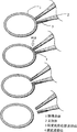
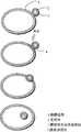
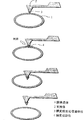
膜破壊部材を用いて膜変性または膜破壊を生じせしめた場合、貫通部の膜と膜破壊部材またはこれを構成する支持体とが密着して接触していると好適であることもある。すなわち、マイクロインジェクションやマイクロマニピュレーション等の操作が可能な、ポンプと接続されている管状構造を有する膜破壊部材の場合、細胞内外の物質輸送の際には貫通部の膜と膜破壊部材またはこれを構成する支持体とが密着して接触していると好適なのである。 When membrane denaturation or membrane breakage is caused by using a membrane breaking member, it may be preferable that the membrane of the penetrating portion and the membrane breaking member or a support constituting the membrane are in close contact with each other. That is, in the case of a membrane disruption member having a tubular structure connected to a pump capable of operations such as microinjection and micromanipulation, the membrane of the penetrating part and the membrane disruption member or the It is preferable that the supporting member is in close contact with each other.
位置制御装置により制御可能な膜破壊部材も細胞処理等の作業には好適に用いられる。位置制御装置としては、原子間力顕微鏡等の走査プローブ顕微鏡、レーザーピンセット、マイクロマニピュレーター等を例示することができる。具体的には、膜破壊部材を構成する支持体として原子間力顕微鏡走査プローブ、近接光走査顕微鏡走査プローブ等を使用することが可能である。 A membrane disrupting member that can be controlled by the position control device is also preferably used for operations such as cell processing. Examples of the position control device include a scanning probe microscope such as an atomic force microscope, laser tweezers, and a micromanipulator. Specifically, an atomic force microscope scanning probe, a proximity light scanning microscope scanning probe, or the like can be used as a support constituting the film breaking member.
本発明は、さらに当業者が適宜簡明な応用を施すことにより、様々な分野における技術として利用されうる。以下にその一例を紹介する。
まず、膜体操作としては、細胞・ウイルスといった膜を持つ物体の操作の機能を有する操作体と、対象となる膜体との結合・接触能力を持つ結合体を膜変成/破壊剤に連結・あるいは併用することで、目的となる膜体に膜破壊/変成とそのほかの操作を行うことが可能である。操作体と結合体と膜変性/破壊剤の三者は、三者単独、あるいは一体が二者を兼ねることも可能である。この場合の対象になる膜はリポソーム・細胞膜・細胞内器官膜・ウィルス膜等であり、結合体はポリクローナル抗体・モノクローナル抗体・金属ビーズ・プラスチックビーズ・ウイルス・細胞・生物等が挙げられる。使用環境としては大気中、液中、生体中等を利用しうる。細胞・ウイルス操作としては変形・破壊・成長促進/抑制・形質転換・細胞死誘発・分裂/融合促進・凝集/解離促進・物質取込/排出促進等を例示できる。
The present invention can be used as a technique in various fields by a person skilled in the art applying a simple application as appropriate. An example is introduced below.
First of all, as membrane operation, an operation body having a function of manipulating an object having a membrane such as a cell or a virus and a conjugate having a binding / contacting ability with a target membrane body are connected to a membrane modifying / disrupting agent. Alternatively, by using together, it is possible to perform film destruction / transformation and other operations on the target film body. The operation body, the combined body, and the membrane denaturing / disrupting agent can be used alone or as a single body. The target membranes in this case are liposomes, cell membranes, intracellular organ membranes, virus membranes, etc., and conjugates include polyclonal antibodies, monoclonal antibodies, metal beads, plastic beads, viruses, cells, organisms, and the like. As the use environment, the atmosphere, liquid, living body, and the like can be used. Examples of cell / virus manipulations include deformation, destruction, growth promotion / suppression, transformation, cell death induction, division / fusion promotion, aggregation / dissociation promotion, substance uptake / excretion promotion, and the like.
細胞膜の一時的な穿孔による物質導入・取出技術としての応用も可能である。例えば、クローン生物の作成や遺伝子治療において、細胞への遺伝子注入は重要な作業である。 It can also be applied as a substance introduction / removal technique by temporary perforation of the cell membrane. For example, gene injection into cells is an important task in the creation of cloned organisms and gene therapy.
細胞融合に本発明を適用することも可能である。細胞融合処理にあたっては、ポリエチレングリコール等の化学物質やセンダイウイルス等のウイルスが利用されてきた本発明の膜変性反応を利用することにより、細胞融合を行うことも可能である。 It is also possible to apply the present invention to cell fusion. In the cell fusion treatment, cell fusion can be performed by using the membrane denaturation reaction of the present invention in which a chemical substance such as polyethylene glycol or a virus such as Sendai virus has been used.
さらには、細胞内に挿入した電極による細胞膜電位を利用した電池を作製することも可能である。マイクロマシンや体内医療機器において、動作動力源の確保は大きな問題である。膜破壊部材と電極とを用いて、細胞膜内外の電位を電力として使用することも可能となり、適宜細胞を電池とするシステムを構築可能である。細胞メスといった細胞レベルの超微小手術用ツールの作製に応用することもできる。手術手段として、各種メス等の様々な生体切開機器があるが、これらの機器は最小のものであっても組織を切開することまでしかできない。細胞以下のレベルの切開機器はこれまで存在しなかったが、本発明による膜破壊技術は細胞膜や核膜など細胞内の膜の切開に適用することが可能である。 Furthermore, it is also possible to produce a battery that utilizes the cell membrane potential of the electrode inserted into the cell. In micromachines and internal medical devices, securing an operating power source is a major problem. Using the membrane disrupting member and the electrode, it becomes possible to use the electric potential inside and outside the cell membrane as electric power, and it is possible to construct a system using cells as batteries as appropriate. It can also be applied to the production of a cell-level ultra-surgical tool such as a scalpel. As a surgical means, there are various living incision devices such as various scalpels, but these devices can only cut tissue even if they are the smallest. Until now, there has been no incision device of sub-cell level, but the membrane disruption technique according to the present invention can be applied to incision of intracellular membranes such as cell membrane and nuclear membrane.
また、遺伝子治療で用い得るドラッグデリバリーシステム(DDS)用薬剤含有ミセル・リポソームの部位特異的な破壊技術として、本発明を提供することができる。すなわち、薬剤の副作用を抑制しつつ、目的となる患部周辺で集中的に使用するためのDDS研究が進められているが、薬剤を入れたマイクロカプセルの破壊を、本発明の膜変成・破壊技術を適用することにより、効率的なDDSが可能である。 Further, the present invention can be provided as a site-specific destruction technique for drug-containing micelles and liposomes for drug delivery system (DDS) that can be used in gene therapy. That is, DDS research for intensive use in the vicinity of the target affected area while suppressing the side effects of the drug is being promoted, but the membrane modification / destruction technology of the present invention is used to destroy the microcapsules containing the drug. By applying, efficient DDS is possible.
細胞内器官の操作にも本発明は適用されうる。すなわち、上記のマイクロマニピュレーターやマイクロインジェクション装置を用いることにより、細胞内のリソソームや核など、細胞内器官を操作が容易となり、ひいては効率のよい細胞処理が可能となる。詳しくは、生殖工学における卵細胞等操作(クローン作成等)を例示することができる。 The present invention can also be applied to the manipulation of intracellular organs. That is, by using the above-described micromanipulator and microinjection apparatus, it becomes easy to manipulate intracellular organs such as intracellular lysosomes and nuclei, and thus efficient cell processing becomes possible. Specifically, an operation such as an egg cell in reproductive engineering (cloning, etc.) can be exemplified.
さらに本発明は、平面・球面等の膜を対象にした機能性分子の配列作業と新規機能発現に利用することも可能である。生体膜においては、様々な機能を持った膜タンパクが膜中で流動しつつ単独で、あるいは適宜離合集散することによって膜面内及び膜内外の化学物質の代謝・電子の伝達等、多様な機能を発揮している。このような膜面内や膜外の移動機能単位の組み合わせによる機能発現はまさに微小化学プラントと呼べるものである。このような反応場としての生体膜の機能発現をモデルに、膜破壊/変成技術により、人工膜や生体膜への各機能単位の取込を制御することで生体機能分子や、圧電素子や光電変換素子や記憶素子等といった人工物も膜デバイスとして組み込み可能になれば、非常に自由度の高い反応システムを構築することが可能になる。 Furthermore, the present invention can also be used for functional molecule alignment work and novel function expression targeting flat and spherical films. In biological membranes, various functions such as metabolism and electron transfer of chemical substances inside and outside the membrane surface by allowing membrane proteins with various functions to flow alone in the membrane, or by appropriately separating and concentrating Is demonstrating. Such functional expression by the combination of the moving functional units in and out of the membrane can be called a microchemical plant. Using the functional expression of the biological membrane as a reaction field as a model, the incorporation of each functional unit into the artificial membrane or biological membrane is controlled by membrane disruption / transformation technology to control biological functional molecules, piezoelectric elements, or photoelectric devices. If artificial objects such as conversion elements and memory elements can be incorporated as membrane devices, it is possible to construct a reaction system with a very high degree of freedom.
さらには、膜操作とデバイス追加による細胞機能拡張を行うこともできる。すなわち、本発明の膜穿孔技術を用いて細胞と人工的な機能体との融合によって既存の細胞に対して新たな機能を付与することが可能となる。例えば、磁性細菌由来の微小磁性体粒子を入れた白血球を作り、磁気的に白血球を患部に誘導すること挙げることができる。これはドラッグデリバリーではなく、セルデリバリーシステムと呼ぶことも可能な新しい技術である。 Furthermore, cell functions can be expanded by membrane operation and device addition. That is, a new function can be imparted to an existing cell by fusing the cell and an artificial functional body using the membrane perforation technique of the present invention. For example, white blood cells containing fine magnetic particles derived from magnetic bacteria can be prepared and the white blood cells can be magnetically induced to the affected area. This is not a drug delivery but a new technology that can be called a cell delivery system.
また、膜に光電変換素子を組み込むことで、細胞に光エネルギーを化学エネルギーに変換する植物細胞に特有な機能を持たせることも可能である。 In addition, by incorporating a photoelectric conversion element into the film, it is possible to give the cell a function specific to plant cells that converts light energy into chemical energy.
さらに、神経細胞の信号入力・出力に、細胞膜に埋め込んだ光電変換素子を適用することにより、光情報処理型のコンピューターと直結して神経細胞を接続することも可能である。 Furthermore, by applying a photoelectric conversion element embedded in a cell membrane to the signal input / output of a nerve cell, it is possible to connect the nerve cell directly connected to an optical information processing computer.
また、マイクロマシンの医療用途への関心は大きい。このような医療用マイクロマシンは血管に入るほど小型である必要があり、動力源は制約を受けることになる。すなわち有線でのエネルギー供給は困難であり、一方マイクロマシンに搭載可能なエネルギーは微々たるものである。このためマイクロマシンによって細胞破壊や細胞改変等、細胞に影響を及ぼすには内蔵エネルギー源による物理的な手段では圧倒的に出力が不足することは明白である。膜破壊剤とその活性化はそのようなマイクロマシンによる細胞操作に必須の手段であるといえる。一例として、膜破壊としてポルフィリン等の赤外線で活性化するような光増感剤を使用することにより、膜破壊に必要なエネルギーを体外から赤外線レーザー等により供給することが可能となる。 In addition, there is a great interest in medical use of micromachines. Such a medical micromachine needs to be small enough to enter a blood vessel, and the power source is limited. That is, it is difficult to supply energy by wire, while the energy that can be mounted on the micromachine is insignificant. For this reason, it is clear that the physical means by the built-in energy source is overwhelmingly insufficient to influence the cells such as cell destruction and cell modification by the micromachine. Membrane disrupting agents and their activation can be said to be indispensable means for cell manipulation by such micromachines. As an example, by using a photosensitizer that is activated by infrared rays such as porphyrin for film breakage, it becomes possible to supply energy necessary for film breakage from outside the body by an infrared laser or the like.
本発明はさらに、個々の神経に電極を接続し、電子情報機器と神経間で情報の授受を行う神経インターフェースの作成に対しても応用することができる。神経情報は一般的に細胞膜電位の変化、すなわち活動電位によって伝達される。この活動電位の発生、計測のための神経インターフェースと総称される、神経情報の入出力を行う神経―電子機器インターフェースが様々に検討されているが、電極と細胞の距離、及び集積度が問題となっている。基礎研究用途のガラス微小電極については細胞膜に刺入、あるいは吸着することで細胞膜電位を直接計測/操作可能であるものの、この電極は直径数ミリメートルのガラス管を加熱加工して作成するために、高密度集積は不可能であった。一方、半導体加工技術で集積化が容易な金属微小電極については細胞膜貫通能力に問題があり、非効率で部位特異性に問題のある細胞外での刺激・計測が行われてきた。本発明による膜穿孔技術と微小金属電極技術を組み合わせることで、細胞膜を穿孔し、細胞内に微小金属電極を設置する事が可能である。これはすなわち細胞と電極を一対一、あるいは細胞一つに電極を複数接続可能な理想的な神経インターフェースとなる。 The present invention can also be applied to the creation of a nerve interface in which electrodes are connected to individual nerves to exchange information between the electronic information device and the nerve. Neural information is generally transmitted by changes in cell membrane potential, that is, action potentials. Various neuro-electronic device interfaces that input and output neural information, which are collectively referred to as neural interfaces for the generation and measurement of action potentials, have been studied, but the distance between electrodes and cells and the degree of integration are problematic. It has become. For glass microelectrodes for basic research, cell membrane potential can be directly measured / operated by inserting or adsorbing to the cell membrane, but this electrode is made by heating a glass tube with a diameter of several millimeters. High density integration was impossible. On the other hand, metal microelectrodes that can be easily integrated by semiconductor processing technology have a problem in the ability to penetrate the cell membrane and have been stimulated and measured outside the cell with inefficiencies and problems with site specificity. By combining the membrane perforation technology and the micro metal electrode technology according to the present invention, it is possible to perforate the cell membrane and install the micro metal electrode in the cell. In other words, this is an ideal nerve interface in which cells and electrodes can be connected one-to-one or a plurality of electrodes can be connected to one cell.
本発明はまた、脳の基礎研究用途等、生体細胞機構解明に応用することが可能である。すなわち、脳機能解析には神経細胞の相互情報交流についての解析が必須であるが、現在、膜電位感受性色素を神経に負荷して、膜電位変化を吸光・蛍光変化として光学的計測によって神経活動を同時多点計測することが行われている。しかしながらこの場合、光学的に神経への入力を行うことは不可能であり、神経への入力と出力を充たすのは電気的な手段、すなわち電極に頼らざるを得ない。また、基板電極上に神経細胞を培養し、人工的にネットワークを形成させて神経の情報処理機構の解析、さらには神経細胞そのものを演算素子として応用する研究が行われている。この場合でも神経への信号入力がネックとなっている。基板上の電極は細胞外電極であり、神経細胞に活動電位発生閾値に達する刺激を与えるためには基盤上の神経集団を刺激し、個々の神経の受けた刺激の総和としてようやく活動電位を発生させうるという状態であった。個々の神経との情報交換を行う電極の集合化の鍵となるのは、電極の細胞レベルまでの小型化並びに個々の細胞に電極を接続する手段であり、半導体プロセス技術で小型化した微小金属電極と膜穿孔技術の併用による細胞内電極挿入は、この目的を充たすものである。 The present invention can also be applied to elucidation of biological cell mechanisms such as basic brain research. In other words, analysis of mutual information exchange between nerve cells is indispensable for brain function analysis, but at present, nerve activity is measured by optically measuring membrane potential changes as absorbance / fluorescence changes by loading membrane potential sensitive dyes into nerves. Simultaneous multipoint measurement is performed. However, in this case, it is impossible to optically input to the nerve, and electrical means, that is, electrodes must be relied upon to satisfy the input and output to the nerve. In addition, research has been conducted in which nerve cells are cultured on a substrate electrode, a network is artificially formed to analyze the information processing mechanism of the nerve, and further, the nerve cell itself is applied as an arithmetic element. Even in this case, signal input to the nerve is a bottleneck. The electrode on the substrate is an extracellular electrode, and in order to give the nerve cell a stimulus that reaches the action potential generation threshold, the nerve group on the base is stimulated, and finally the action potential is generated as the sum of the stimuli received by each individual nerve. It was in a state that could be allowed. The key to the assembly of electrodes for exchanging information with individual nerves is the miniaturization of the electrodes to the cell level and the means to connect the electrodes to individual cells. Intracellular electrode insertion by the combined use of electrodes and membrane perforation technology serves this purpose.
本発明はさらに、機能的電気刺激用等、侵襲計測型医療用電極の高集積・高精度化に利用することが可能である。リハビリテーション医学の一環として、神経・筋肉の機能回復のために金属電極を神経束に挿入し電気刺激を行う、機能的電気刺激と呼ばれる手法が用いられている。現在、電極は神経束内に数カ所配置されるに留まっており、神経刺激の部位特異性/精度の面では不十分である。膜穿孔技術と既存の電極集積化技術の複合化により神経と電極の一対一接合を行うことが可能であり、それにより、機能回復が必要な神経に対してのみ電気刺激を行うことが可能となる。 The present invention can be further used for highly integrated and highly accurate medical electrodes for invasive measurement such as for functional electrical stimulation. As part of rehabilitation medicine, a technique called functional electrical stimulation is used in which a metal electrode is inserted into a nerve bundle and electrical stimulation is performed in order to restore the function of nerves and muscles. Currently, only a few electrodes are placed in the nerve bundle, which is insufficient in terms of site specificity / accuracy of nerve stimulation. By combining membrane perforation technology and existing electrode integration technology, it is possible to perform one-to-one junctions between nerves and electrodes, thereby enabling electrical stimulation only to nerves that require functional recovery. Become.
また本発明は、種々の人工臓器に神経からの信号を伝達する技術として応用することが可能である。体内に埋込まれた器官の制御手段は、生体の直接的な神経情報によらず、あくまでも間接的な制御に留まっている。一例としては人工尿道弁の制御が挙げられる。形状記憶合金により作成されたこの弁は、加熱により開き、通常体温では閉じる。問題なのは体外の加熱装置のスイッチにより弁の開閉が行われることにあり、本人の意志によって直接弁の開閉が制御されるわけではない。膜貫通電極を用いた神経インターフェースによって神経情報の安定・高精度な計測が可能になれば、このような弁をあたかも使用者本人の体の一部であるように制御可能になる。確かに尿道弁は、使用頻度は一日数回程度で操作も開閉という簡単な器官であり、体外のスイッチ操作による生活上の不便はさほどではないと思われる。しかし、より高度な内臓機能の代行を行うような人工器官を制御するには、自律神経等を制御信号源とすることが不可欠である。 Further, the present invention can be applied as a technique for transmitting signals from nerves to various artificial organs. The control means of the organ embedded in the body is merely indirect control regardless of the direct nerve information of the living body. An example is control of an artificial urethral valve. This valve made of shape memory alloy opens by heating and closes at normal body temperature. The problem is that the valve is opened and closed by an external heating device switch, and the opening and closing of the valve is not directly controlled by the person's will. If nerve information using a transmembrane electrode enables stable and highly accurate measurement of nerve information, such a valve can be controlled as if it were a part of the user's body. Certainly, the urethral valve is a simple organ that is used several times a day and can be opened and closed, and it seems that there are not many inconveniences in life due to the operation of an external switch. However, in order to control a prosthesis that performs a substitute for a higher level of visceral function, it is indispensable to use an autonomic nerve or the like as a control signal source.
本発明はさらに人体同様に制御可能な間接や感覚器官を備えた義手・義足等の接続・制御にも用い得る。現在、交通事故等による四肢切断後の機能補助のための動力義手・動力義足等の機器の性能向上が著しい。しかしながらその制御情報源は装着者の残存している筋電を利用するものがほとんどであり、本来の四肢の制御に要する情報量に比較すると圧倒的に少ない。また、義手・義足からの装着者側への感覚の伝達に至っては、義手装着部を介した物理的接触情報程度に限られている。そのため訓練によってそのような義手・義足の操作を習得しても、実際には大きな不便を強いられつつ使用するというのが現状である。この装着者と人工肢との間の情報授受経路が貧弱であることが、人工肢の性能向上を妨げる原因の一つとなっている。膜貫通電極を用いた神経インターフェースによって個々の神経情報の安定・高精度な計測が可能になれば、装着者の切断肢につながっていた神経にインターフェースを接合することでこれを人工肢の制御情報源、感覚信号入力端子として使用できる。すなわち、本来の体と変わらない運動性能・感覚器官を備えた人工肢を制御することが可能になる。 The present invention can also be used for connection / control of a prosthetic hand, a prosthetic leg or the like equipped with an indirect or sensory organ that can be controlled in the same manner as the human body. At present, the performance improvement of devices such as power prostheses and power prostheses for assisting functions after limb cutting due to a traffic accident or the like is remarkable. However, most of the control information sources use the remaining electromyogram of the wearer, which is overwhelmingly smaller than the amount of information required for the original limb control. In addition, the transmission of senses from the prosthetic hand and the prosthetic leg to the wearer side is limited to the physical contact information via the prosthetic hand wearing part. For this reason, even if such a prosthetic hand / leg prosthesis operation is acquired through training, the actual situation is that it is used with great inconvenience. The poor information exchange path between the wearer and the artificial limb is one of the causes that hinders the performance improvement of the artificial limb. If the nerve interface using the transmembrane electrode enables stable and highly accurate measurement of individual nerve information, it can be used to control the artificial limb by joining the interface to the nerve connected to the wearer's amputated limb. Can be used as a source and sensory signal input terminal. That is, it becomes possible to control an artificial limb having a motor performance / sensory organ that is not different from the original body.
さらに本発明は、人工感覚器官(視覚・聴覚等)と生体との接続・制御に利用しうる。すでに、聴覚機能再建のために人工内耳がある。これは鼓膜−内耳の機能をマイクロホンと信号変換回路によって代行するもので、蝸牛器官に数十個の電極を設置して、聴覚神経を電気刺激し聴覚情報を脳に送信する。この機器が医療機器として成立した最大の理由は、聴覚神経が周波数帯に応じて整列している蝸牛器官にある。この器官は特例的に電極から神経に非常に情報を送りやすく、この人工内耳の電極技術を他の器官には適用不可能である。感覚器官の中でも、生体の情報源として特に重要な視覚の機能再建に必要な、直径1cmあたり100万本の神経軸索を含む視神経に接続するに足る電極系は一つの技術上の目標である。現在そのような高密度で集積可能な神経用電極は存在しないが、膜貫通電極を用いた神経インターフェースは視神経に対応した高密度集積化も可能である。既に光学機器は電荷結合素子(CCD)を用いた製品が安価に100万画素を実現しているため、このような光学情報入力機器を機能性義眼として用い、神経インターフェースを介して人体の側に視覚を提供することも可能である。 Furthermore, the present invention can be used for connection / control of an artificial sensory organ (sight, hearing, etc.) and a living body. There is already a cochlear implant for the reconstruction of auditory function. This substitutes the function of the eardrum-inner ear with a microphone and a signal conversion circuit. By installing dozens of electrodes in the cochlear organ, the auditory nerve is electrically stimulated to transmit auditory information to the brain. The biggest reason that this device was established as a medical device is the cochlear organ in which the auditory nerves are arranged according to the frequency band. This organ is exceptionally easy to send information from the electrode to the nerve, and this cochlear implant electrode technology is not applicable to other organs. Among the sensory organs, an electrode system sufficient to connect to the optic nerve including 1 million nerve axons per 1 cm in diameter, which is necessary for the reconstruction of visual functions, which is particularly important as a biological information source, is one technical goal. . Currently, there is no electrode for nerves that can be integrated at such a high density, but a nerve interface using a transmembrane electrode can be integrated at a high density corresponding to the optic nerve. Since optical devices already use charge-coupled devices (CCDs) have already achieved 1 million pixels at low cost, such optical information input devices are used as functional prosthetics and are connected to the human body via a nerve interface. It is also possible to provide vision.
本発明は、さらに脳機能拡張にも応用しうる。情報処理装置としての脳は半導体マイクロプロセッサと比較して、省エネルギー、並列処理、等の利点を持つ反面、情報保持の不正確さ、学習の困難等の弱点を併せ持つ。脳の利点を生かしつつ、このような弱点を補強するために、神経インターフェースを介して既存の半導体デバイスを脳と連動併用することも可能である。 The present invention can also be applied to brain function expansion. The brain as an information processing apparatus has advantages such as energy saving and parallel processing, but has weak points such as inaccuracy of information retention and difficulty in learning. In order to reinforce such weak points while taking advantage of the brain, it is also possible to use an existing semiconductor device in conjunction with the brain via a nerve interface.
以下実施例により本発明を具体的に説明するが、本発明はこれらの実施例に限定されるものではない。 EXAMPLES The present invention will be specifically described below with reference to examples, but the present invention is not limited to these examples.
[実施例1] 神経系株化細胞PC12の培養
神経系株化細胞PC12細胞は、中枢神経のモデルとして用いられるラット副腎髄質由来の神経節類似細胞である。熱非働化した馬血清10%、牛胎児血清5%、L-グルタミン酸 7.35 mg/l、L-グルタミン 2 mMを含むNeuroBasal Medium(GIBCO BRL社製) (pH 7.3)を用いてPC12細胞を95% CO2下で培養した。
[Example 1] Culture of neural cell line PC12 Nervous cell line PC12 cell is a ganglion-like cell derived from rat adrenal medulla used as a model of central nerve. 95% PC12 cells using NeuroBasal Medium (GIBCO BRL) (pH 7.3) containing 10% heat-inactivated horse serum, 5% fetal bovine serum, 7.35 mg / l L-glutamic acid, 2 mM L-glutamine CO 2 were cultured under.
継代培養は、培地を細胞に吹き付け培養フラスコ壁面よりはがし、300g、5分の遠心分離により細胞を集めた後、底面積25 cm2の培養フラスコ(IWAKI Glass社製)内に 1 mlあたり1〜3×10⁴ cells/cm2となるように細胞をまき、2〜3日毎に 培地交換することにより行った。 In subculture, the medium is sprayed onto the cells, peeled off the walls of the culture flask, collected by centrifugation at 300 g for 5 minutes, and then placed in a culture flask (made by IWAKI Glass) with a bottom area of 25 cm 2 per ml. The cells were seeded at ˜3 × 10 4 cells / cm 2 and the medium was changed every 2-3 days.
PC12細胞を神経様細胞に分化させる際にはマウス神経成長因子(Nerve Growth Factor, NGF)2.5Sを最終濃度50 ng/mlとなるように培地に添加した。培地添加用NGF (Murine, 2.5S ) 分散液調製法は以下の通りである。
1) リン酸緩衝食塩水(phosphate buffered saline,PBS;組成は、KH2PO4 2.10 g/l、NaCl 90.00 g/l、NaHPO4・7H2O 7.26 g/l、1 N NaOH液でpH pH 7.4に調整した。)
2) 牛血清アルブミン(Bovine Serum Albumin,BSA) 2 mgを 上記 PBS 1000 μl(pH 7.4に調整済)に分散し、分散液を ポアサイズ0.22 μmのフィルタを通し滅菌し た。
3) この滅菌液100 μlと NGF solution 100 μg/ml(GIBCO BRL社市販品)を加え全量を200 μlに調整し、これを8 μlづつミニチューブに入れ、-20℃で凍結保存し た。
When differentiating PC12 cells into neuron-like cells, mouse nerve growth factor (NGF) 2.5S was added to the medium to a final concentration of 50 ng / ml. The method for preparing NGF (Murine, 2.5S) dispersion for medium addition is as follows.
1) Phosphate buffered saline (PBS); composition is KH 2 PO 4 2.10 g / l, NaCl 90.00 g / l, NaHPO 4 · 7H 2 O 7.26 g / l, pH pH with 1 N NaOH solution (Adjusted to 7.4)
2) 2 mg of bovine serum albumin (BSA) was dispersed in 1000 μl of the above PBS (adjusted to pH 7.4), and the dispersion was sterilized through a filter with a pore size of 0.22 μm.
3) 100 μl of this sterilizing solution and 100 μg / ml NGF solution (GIBCO BRL commercial product) were added to adjust the total volume to 200 μl, and each 8 μl was placed in a minitube and stored frozen at −20 ° C.
このように分注したNGF液を培地に1000倍希釈となるように添加することにより、PC12細胞を分化させた。
PC12細胞はプラスチックボトルの壁面に弱く接着し、小さいクラスターを形成しながら生育した。神経化した細胞の培養にはコラーゲンコートディッシュ(IWAKI Glass社製)を使用した。
以下の電気生理実験には神経様細胞に分化開始後六日以上経過した細胞を使用した。
The PC12 cells were differentiated by adding the NGF solution dispensed in this manner to the medium so as to be diluted 1000-fold.
PC12 cells attached weakly to the wall of the plastic bottle and grew while forming small clusters. A collagen coat dish (manufactured by IWAKI Glass) was used for culturing the neuronized cells.
In the following electrophysiological experiment, cells that had passed 6 days or more after the start of differentiation were used as nerve-like cells.
[実施例2] ビスアミノメチルターチオフェンの合成
使用した光増感剤はαターチエニル誘導体、5'5"-bis(aminomethyl)-2,2':5',2"-terthiophene (BAT)である。本化合物は六車により論文[J. Heterocyclic Chem., 33, 1-6 (1996)]に従って合成され、 BAT二塩酸塩の状態で提供された。BAT二塩酸塩の構造式を図1に示した。
アミノメチル基を末端に持つチオフェンオリゴマーは末端アミノメチル基ゆえに同種の他の誘導体に比較して水溶性が高い。このアミノメチル基の解離状態によって水溶性は変化する。一方、本BATの場合は、酸性水溶液中では二価の正電 荷を持ち容易に溶解するが、生体に適した pH領域(7.4付近)の水溶液中では、一価の正電荷を持ち水溶性の高さを維持しているもの及び、無電価になりコロイド状に凝集しやすいものが共存する性質を持つ。この pH条件下においてBAT分散液で細胞を灌流することで、この分子を細胞表面に容易に付加させることが可能となった。BAT分子の親水性は、αターチエニル誘導体をはじめとする他の修飾 チオフェンオリゴマーに限らず、導電性高分子モノマーとして設計された他の分子には類のない新規な性質である。
[Example 2] Synthesis of bisaminomethylterthiophene The photosensitizer used was an α-tertienyl derivative, 5'5 "-bis (aminomethyl) -2,2 ': 5', 2" -terthiophene (BAT). . This compound was synthesized by Rokusha according to the paper [J. Heterocyclic Chem., 33, 1-6 (1996)] and provided in the form of BAT dihydrochloride. The structural formula of BAT dihydrochloride is shown in FIG.
A thiophene oligomer having an aminomethyl group at the terminal is higher in water solubility than other derivatives of the same kind because of the terminal aminomethyl group. The water solubility changes depending on the dissociation state of the aminomethyl group. On the other hand, this BAT easily dissolves in an acidic aqueous solution with a divalent positive charge, but in an aqueous solution in the pH range (near 7.4) suitable for living organisms, it has a monovalent positive charge and is water-soluble. That maintain a high height and those that easily become aggregated in a colloidal form without being charged. By perfusing cells with BAT dispersion under this pH condition, this molecule could be easily added to the cell surface. The hydrophilicity of the BAT molecule is not limited to other modified thiophene oligomers such as α-tertienyl derivatives, but is a novel property unique to other molecules designed as conductive polymer monomers.
[実施例3] 光照射後の膜抵抗と膜電位の測定
細胞レベルでの微小な膜障害を、回復過程も含めて秒から数分のオーダーでモニタリングする必要があるため、電気生理実験の手法であるパッチクランプ法により細胞膜間電位、あるいは細胞膜を透過するイオン電流を測定した。
[Example 3] Measurement of membrane resistance and membrane potential after light irradiation Since it is necessary to monitor minute membrane damage at the cellular level in the order of seconds to several minutes including the recovery process, a method of electrophysiological experiment The intermembrane potential or the ionic current that permeates the cell membrane was measured by the patch clamp method.
光増感剤BAT は HEPES(25mM,pH7.4)緩衝液に分散した。マイクロピペットにより細胞近傍に局所的に添加するための分散液は BAT濃度 2 mM、灌流液全体に 添加するための分散液は BAT濃度 0.2 mMに調整した。 The photosensitizer BAT was dispersed in HEPES (25 mM, pH 7.4) buffer. The dispersion for adding locally in the vicinity of the cells with a micropipette was adjusted to a BAT concentration of 2 mM, and the dispersion for adding to the entire perfusate was adjusted to a BAT concentration of 0.2 mM.
細胞を2 mlの電気生理実験用培地中、室温でインキュベートした。
この実験用に用いた培地は、最終的にNaOH添加によりpH 7.4に調整した、NaCl, 124mM; KCl, 5mM; CaC12.2H2O, 2.4mM; MgSO4・7H2O, 1.3mM; glucose 10mMである。蒸発による影響を防ぐため、電気生理実験用培地は最長でも40分 に一度はピペットにより交換した。
Cells were incubated at room temperature in 2 ml electrophysiological laboratory medium.
The medium used for this experiment was adjusted to pH 7.4 by the final addition of NaOH, NaCl, 124mM; KCl, 5mM ;
BATは最終濃度が49 μMとなるように添加した。照射光量は0.47 J/cm2、 0.94 J/cm2、1.57 J/cm2の3段階とした。 BAT was added to a final concentration of 49 μM. The amount of irradiation light was set to three levels of 0.47 J / cm 2 , 0.94 J / cm 2 , and 1.57 J / cm 2 .
パッチ電極内液は以下の組成とした。(KCl 132 mM, NaCl, 8 mM, MgCl2, 2 mM, HEPES 30 mM, Na2ATP 4 mM, GTP 0.3 mM, EGTA 0.5 mM, これを最終的にNaOH添加によりpH 7.3に調整したもの) The solution in the patch electrode had the following composition. (KCl 132 mM, NaCl, 8 mM, MgCl 2 , 2 mM, HEPES 30 mM, Na 2 ATP 4 mM, GTP 0.3 mM, EGTA 0.5 mM, which was finally adjusted to pH 7.3 by adding NaOH)
励起光源は共焦点レーザー顕微鏡(confocal laser scanning microscope,CLSM) MRC-1000 UV (BIO-RAD laboratories社製)を標準装備している 50mW, 363nm アルゴンイオンレーザーを使用した。顕微鏡フル画面(約470 μm×680 μm)の1/16(X軸、Y軸方向それぞれ1/4、117 μm×170 μm)を前述のレーザ ー光でスキャンする。このエリアに、パッチされたターゲット細胞全体が入るように設定した。レーザー光は50 mWが100 %出力である。スキャン速度により、 照射時間は1/16 , 1/4 , 1/32 秒から選択した。また、フィルタによる減光も使用した。ズーム機能を使用した場合は通常のエリアに比べ光を狭いエリアで集中してスキャンするため、単位面積あたりの光量はズーム倍率の二乗に比例して増加することになる。実際に細胞に励起光が届くまでにはコラーゲンコートディッシュのプラスチックを透過するため、実際には減光を考慮する必要がある。 The excitation light source was a 50 mW, 363 nm argon ion laser equipped with a confocal laser scanning microscope (CLSM) MRC-1000 UV (manufactured by BIO-RAD laboratories) as standard equipment. 1/16 of the full microscope screen (about 470 μm × 680 μm) (1/4 in the X-axis and Y-axis directions, 117 μm × 170 μm) is scanned with the laser beam described above. This area was set to contain the entire patched target cell. The laser beam is 100% output at 50 mW. The irradiation time was selected from 1/16, 1/4 and 1/32 seconds depending on the scanning speed. Also, dimming with a filter was used. When the zoom function is used, light is concentrated and scanned in a narrower area than in a normal area, so the amount of light per unit area increases in proportion to the square of the zoom magnification. Actually, it is necessary to consider the dimming because the collagen-coated dish passes through the plastic until the excitation light actually reaches the cells.
また、励起光照射は電気生理記録と連動したTTL信号を光源に適宜送信し、光照射と電気的測定の同期をとった。 Moreover, the excitation light irradiation transmitted the TTL signal interlock | cooperated with the electrophysiological recording suitably to the light source, and synchronized light irradiation and the electrical measurement.
電気生理実験の開始にあたり、細胞膜電位は-80 〜 -60 mVの間に維持されて いた。パッチ電極の抵抗は 3〜4 MΩで、前述の電極内液を充填して用いた。 At the start of the electrophysiology experiment, the cell membrane potential was maintained between -80 and -60 mV. The patch electrode had a resistance of 3 to 4 MΩ, and was filled with the above-described electrode solution.
細胞膜電位測定用のアンプは Axopatch 1-D (Axon Instruments社製)を使用した。膜抵抗は 350ミリ秒 、1 Hz の矩形波過分極電流を通電した際の膜電位変化より算出した。通電量( 0.1または 0.15 nA) は通電による膜電位変化が30mVを 越えないように選択した。なおこの実験条件下ではPC12細胞は活動電位を発生しなかった。測定された電位・電流の値を Axoscope ver.1.1ソフトウェア(Axon Instruments社製)により解析した。この結果を図9に示した。 Axopatch 1-D (Axon Instruments) was used as an amplifier for measuring cell membrane potential. The membrane resistance was calculated from the change in membrane potential when a rectangular wave hyperpolarizing current of 1 Hz was applied for 350 milliseconds. The energization amount (0.1 or 0.15 nA) was selected so that the membrane potential change due to energization did not exceed 30 mV. Under these experimental conditions, PC12 cells did not generate action potentials. The measured potential / current values were analyzed using Axoscope ver.1.1 software (Axon Instruments). The results are shown in FIG.
図9において横軸は時間経過を示している(単位;秒)。縦軸は上段が光照射前の値を100%として規格化した場合の細胞膜抵抗(単位;%)を、下段が細胞膜電位(単位;mV)をそれぞれ示している。膜抵抗はイオン透過阻止能、膜電位は各種膜間イオン輸送系の活動による膜の能動的イオン輸送能及びイオン透過阻止能を反映している。 In FIG. 9, the horizontal axis indicates the passage of time (unit: second). The vertical axis shows the cell membrane resistance (unit:%) when the upper part is normalized with the value before light irradiation as 100%, and the lower part shows the cell membrane potential (unit: mV). The membrane resistance reflects the ion permeation blocking ability, and the membrane potential reflects the active ion transport ability and ion permeation blocking ability of the membrane due to the activity of various transmembrane ion transport systems.
1.57 J/cm2の光照射量は、Aがもっとも弱く(0.47 J/cm2)Bが2番目に弱く (0.94 J/cm2)、Cがもっとも強い(1.57 J/cm2)。Aにおいては細胞膜抵抗・膜電位とも光照射後に若干の変動があるものの、大きな変化はなかった。Bにおいては、光照射後に数秒の誘導期間をおいて細胞膜抵抗減少・膜電位脱分極が生じた。また、この条件下では、30秒後に光照射前の抵抗・電位に回復することが観察された。これはすなわち膜がいったん破壊された後に生体反応により膜の修復がなされたものと考えられる。Cにおいては光照射後に数秒の誘導期間をおいて8秒程度で細胞膜抵抗・膜電位とも消失し、その後一定値をとった。これはすなわち膜がいったん破壊された後に修復反応がおこっていない、すなわち不可逆的な膜破壊が生じたものと考えられる。 The light irradiation dose of 1.57 J / cm 2 is the weakest in A (0.47 J / cm 2 ), the second weakest in B (0.94 J / cm 2 ), and the strongest in C (1.57 J / cm 2 ). In A, both cell membrane resistance and membrane potential were slightly changed after light irradiation, but there was no significant change. In B, cell membrane resistance decrease and membrane potential depolarization occurred after an induction period of several seconds after light irradiation. Under these conditions, it was observed that after 30 seconds, the resistance / potential before light irradiation was recovered. That is, it is considered that the membrane was repaired by a biological reaction after the membrane was once destroyed. In C, both cell membrane resistance and membrane potential disappeared in about 8 seconds after an induction period of several seconds after light irradiation, and then took a constant value. This is considered to be because the repair reaction did not occur after the film was broken once, that is, irreversible film breakage occurred.
[実施例4] 微小ガラスピペットによる標的細胞へのBATの吹き付け処理
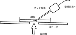
マイクロマニピュレーターに保持された微小ガラスピペットにマイクロインジェクション装置を接続し、微小ガラスピペット内部に光増感剤BAT分散液(BAT濃度 2 mM、水溶媒)を充填した。このガラスピペット先端が、パッチ電極に接続され膜電位・膜抵抗を計測する細胞の近傍 200 μm以内になるように配置した。微小ガラスピペットを加圧することによりBAT分散液を放出し、目的となる細胞膜にBATを付着させた。レーザー光を実施例3と同様に照射したところ、細胞膜 電位の脱分極が観察された。
[Example 4] Treatment of spraying BAT on target cells with a micro glass pipette A microinjection device was connected to a micro glass pipette held by a micromanipulator, and a photosensitizer BAT dispersion (
[実施例5]部位特異的膜破壊を利用したマイクロインジェクション処理
膜破壊を利用した物質導入をマイクロインジェクション処理に適用した。
マイクロインジェクション処理の成否を判定するため、インジェクション液に水溶性蛍光色素Lucifer Yellow CH ( LY ) を添加した。インジェクション処理後、蛍光顕微鏡によって細胞内にLY由来の黄色蛍光が観察された場合をインジェクション処理が成功したものと判定した。インジェクション液中の光増感剤BATの有無、およびBAT励起光照射の有無によって、細胞へのLYインジェクション成功率がどのように変化するか評価を行った。
[Example 5] Microinjection treatment utilizing site-specific membrane disruption Substance introduction utilizing membrane disruption was applied to the microinjection treatment.
In order to determine the success or failure of the microinjection treatment, a water-soluble fluorescent dye Lucifer Yellow CH (LY) was added to the injection solution. After the injection treatment, it was determined that the injection treatment was successful when yellow fluorescence derived from LY was observed in the cells with a fluorescence microscope. It was evaluated how the success rate of LY injection into cells changes depending on the presence or absence of the photosensitizer BAT and the presence or absence of BAT excitation light irradiation in the injection solution.
LYはマイクロインジェクションに用いられる低毒性の蛍光色素であり、細胞分裂の際、娘細胞に移行する特徴がある[Cell & Tissue Res., 234, 309-318 (1983)]。LYは水溶性が高く、拡散性に優れるため、神経系の細胞蛍光ラベル剤としても用いられる[Cell & Tissue Res., 254, 561-571(1988)]。また、細胞間の液―液接合であるギャップ接合[「新生理学体系7 発生・分化の生理学 第4章 細胞間連結の発生 I.電気的結合」、医学書院 (1991)]を通じて、このギャップ接合で連結された細胞間を分単位で迅速に移行する特徴がある。使用したPC12細胞についても、同様のギャップ接合形成のマーカーとして用いられた報告がなされている[J. Neurosci., 14, 3945-3957 (1994)]。LYを注入された細胞は過大なLY励起光照射に対しては細胞死を引き起こす[Science, 206, 702-704 (1979)]が、インジェクション液中のBATの有無、およびBAT励起光照射の有無によって、細胞へのインジェクション成功率がどのように変化するか、比較評価した。 LY is a low-toxic fluorescent dye used for microinjection, and has a characteristic of transferring to a daughter cell during cell division [Cell & Tissue Res., 234, 309-318 (1983)]. Since LY is highly water-soluble and excellent in diffusibility, it is also used as a cellular fluorescent labeling agent for the nervous system [Cell & Tissue Res., 254, 561-571 (1988)]. Through this gap junction, which is a fluid-liquid junction between cells [“New Physiological System 7 Physiology of Development and Differentiation, Chapter 4. Generation of Intercellular Connections I. Electrical Coupling”, Medical School (1991)]. It is characterized in that it quickly moves in minutes between connected cells. The PC12 cells used have also been reported to be used as similar markers for gap junction formation [J. Neurosci., 14, 3945-3957 (1994)]. Cells injected with LY cause cell death in response to excessive LY excitation light irradiation [Science, 206, 702-704 (1979)], but the presence or absence of BAT in the injection solution and the presence or absence of BAT excitation light irradiation It was compared and evaluated how the success rate of the injection into the cell changes.
通常、マイクロインジェクションを成功させる場合には、先端開口部の直径が数百ナノメートルであるガラス細管(キャピラリー)を高速で細胞に接触させ、物理的に、瞬時に細胞膜、あるいは核膜を貫通・穿孔する必要がある。実験においてはプログラム動作可能な電動マイクロマニピュレーター(Eppendorf社製、Micromanipulator5171)および電動インジェクター(Eppendorf社製、Transjector5246)を使用し、キャピラリーの接触速度を任意の値に設定することが可能であった。また、インジェクション用キャピラリーは同装置用に市販された量産品(Eppendorf社製、FemtoTips)を用いた。電動マイクロマニピュレーターによりインジェクション作業が再現性よく自動化されたこと、また自作品に比較して形状の均一性が高い市販のキャピラリーを使用したことから、インジェクション成功効率についての統計的処理を行うことが可能になった。なお、マイクロマニピュレーターは蛍光顕微鏡(オリンパス光学工業製、IX70蛍光顕微鏡仕様)に装備した。光増感剤の励起光源としては、同顕微鏡内蔵の落射蛍光光源である100 W水銀ランプの光を紫外線励起フィルタセット(オリンパス光学工業製、U-MWUミラーユニット)で透過処理した紫外光を使用した。光照射面積は顕微鏡の蛍光光学系の絞りによって直径約100μmとした。また細胞内にLYが注入されたことを判定するためのLY励起光源としては、同じく100 W水銀ランプの光を紫色光励起フィルタセット(オリンパス光学工業製、U-MWBVミラーユニット)で透過処理した紫色光を使用した。 Normally, when microinjection is successful, a glass capillary (capillary) with a tip opening diameter of several hundred nanometers is brought into contact with the cell at high speed, physically and instantly penetrating the cell membrane or nuclear membrane. Need to drill. In the experiment, a programmable electric micromanipulator (Eppendorf, Micromanipulator5171) and electric injector (Eppendorf, Transjector 5246) were used, and the capillary contact speed could be set to an arbitrary value. The injection capillary used was a mass-produced product (Eppendorf, FemtoTips) marketed for the apparatus. The injection process can be automated with an electric micromanipulator with high reproducibility, and the use of a commercially available capillary with higher uniformity of shape compared to the original work enables statistical processing of the injection efficiency. Became. The micromanipulator was installed in a fluorescence microscope (Olympus Optical Industry Co., Ltd., IX70 fluorescence microscope specification). As the excitation light source for the photosensitizer, ultraviolet light obtained by transmitting light from a 100 W mercury lamp, an epifluorescence light source built in the microscope, with an ultraviolet excitation filter set (U-MWU mirror unit, manufactured by Olympus Optical Co., Ltd.) is used. did. The light irradiation area was about 100 μm in diameter by the stop of the fluorescence optical system of the microscope. Also, as a LY excitation light source for determining that LY was injected into the cell, a purple light obtained by transmitting the light of a 100 W mercury lamp with a purple light excitation filter set (U-MWBV mirror unit, manufactured by Olympus Optical Co., Ltd.) Used light.
このような系では、光増感剤BATがキャピラリーに接した直径 0.5 μmの領域に集中され、キャピラリーが接している領域以外については、BATは拡散によって速やかに希釈された。そのため、キャピラリー接触部ではBATによる光増感作用がインジェクション液のBAT濃度 100 μMに細胞に作用するBAT濃度としては、キャピラリー接触部の濃度に比較するとその他の部位の濃度は無視できると思われる。 In such a system, the photosensitizer BAT was concentrated in a region having a diameter of 0.5 μm in contact with the capillary, and BAT was rapidly diluted by diffusion except in the region in contact with the capillary. Therefore, the BAT concentration at which the photosensitizing effect of BAT acts on the cells at the BAT concentration of 100 μM in the injection solution at the capillary contact portion seems to be negligible compared to the concentration at the capillary contact portion.
インジェクション作業に際しては、キャピラリー接触速度1000 μm s-1で細胞にキャピラリーが刺入できるようにマニピュレーターの動作範囲を設定した上で、キャピラリーを7μm s-1の低速度で動作させ、物理的に細胞膜を穿孔しないようにキャピラリーを細胞膜に接触させた。この条件で、BATによる光増感作用によって細胞のインジェクション成功効率がどのように変化するか比較を行った。 During the injection operation, the operating range of the manipulator is set so that the capillary can be inserted into the cell at a capillary contact speed of 1000 μm s −1 , and then the capillary is operated at a low speed of 7 μm s −1 to physically connect the cell membrane. The capillary was brought into contact with the cell membrane so as not to perforate. Under these conditions, we compared how the cell injection success efficiency was changed by the photosensitizing effect of BAT.
光増感剤BATは六車らにより合成・提供されたものを使用した。以下の試薬については市販品を使用した。
塩化ナトリウム(NaCl、キシダ科学製)、塩化カリウム(KCl、キシダ科学製)、リン酸水素二ナトリウム(Na2HPO4、和光純薬製)、リン酸二水素カリウム(KH2PO4、和光純薬製)、蛍光マーカー Lucifer Yellow CH, Lithium salt(LY、ex.428 nm, em.536 nm. Moleculer Probes 社製)
The photosensitizer BAT was synthesized and provided by Rokusha et al. Commercially available products were used for the following reagents.
Sodium chloride (NaCl, manufactured by Kishida Scientific), potassium chloride (KCl, manufactured by Kishida Scientific), disodium hydrogen phosphate (Na 2 HPO 4, manufactured by Wako Pure Chemical Industries), potassium dihydrogen phosphate (KH 2 PO 4, Wako Pure) ), Fluorescent marker Lucifer Yellow CH, Lithium salt (LY, ex.428 nm, em.536 nm. Moleculer Probes)
インジェクション液の組成は以下の最終濃度になるように各成分を純水に溶解、調整した。(光増感剤 BAT 100 μM、HCl 50 μM、蛍光マーカー LY 2 mM、NaCl 8 g/l, KCl 0.2 g/l, Na2HPO4 1.15 g/l, KH2PO4 0.2 g/l)
なおBATを含まない対照処理用のインジェクション液も調整した。
Each component was dissolved and adjusted in pure water so that the composition of the injection solution had the following final concentration. (
A control treatment injection solution containing no BAT was also prepared.
インジェクション対象細胞には神経系株化細胞PC12を使用した。同細胞は理化学研究所細胞開発銀行より入手し、実施例1に従って培養された。なおインジェクション処理される細胞はφ35 mm コラーゲンコート済ディッシュ(岩城硝子製)へ細胞密度90000 cell / ディッシュで継代培養を行った。細胞は炭酸ガスインキュベーター (Forma Scientific社製)により気温摂氏37度、二酸化炭素5%、空気95%、湿度100%の環境下で培養された。 Neural cell line PC12 was used as the injection target cell. The cells were obtained from RIKEN Cell Development Bank and cultured according to Example 1. The cells to be injected were subcultured to a φ35 mm collagen-coated dish (Iwaki Glass) at a cell density of 90000 cells / dish. The cells were cultured in a carbon dioxide incubator (Forma Scientific) in an environment of 37 degrees Celsius, 5% carbon dioxide, 95% air, and 100% humidity.
インジェクション処理に際しては、Hibernate A Media (Hib-A、Gibco BRL社製) [NeuroReport, 7, 1509-1512 (1996)]にウマ血清(Gibco BRL社製) 10%、ウシ胎児血清(三菱化学製、中標津牛準胎児血清)5%、L-グルタミン酸(Gibco BRL社製) 7.35 mg/l、L-グルタミン(Gibco BRL社製) 2 mMを添加した組成のインジェクション処理用Hib-A培地を用いた。なお、ウマ血清については56℃、30分の加熱により熱非働化処理したものを使用した。 In the injection treatment, Hibernate A Media (Hib-A, Gibco BRL) [NeuroReport, 7, 1509-1512 (1996)] equine serum (Gibco BRL) 10%, fetal bovine serum (Mitsubishi Chemical, A Hib-A medium for injection treatment having a composition to which 5% of Nakashibetsu calf semi-fetal serum), L-glutamic acid (Gibco BRL) 7.35 mg / l, and L-glutamine (Gibco BRL) 2 mM were added was used. The horse serum was heat-inactivated by heating at 56 ° C. for 30 minutes.
以上の溶液調整には純水製造装置 Biocel A10 / Elix 10 (MILLIPORE社製)により精製された水を使用した。 In the above solution adjustment, water purified by a pure water production apparatus Biocel A10 / Elix 10 (MILLIPORE) was used.
インジェクション処理手順の概略を 図10に示す。以下はその補足である。
1)インジェクション処理時には細胞が培養されたディッシュからNeuroBasal 培地の全量3 mlを除去し、ディッシュ上の細胞をPhosphate Buffered Saline, 7.4 Ca、Mg不含(PBS、 GIBCO BRL社製) 1 mlを流すことによって洗浄した。このPBS全量を除去し、新たなPBS 1 mlで同様に洗浄を行った後、PBS全量を除去し、最終的にディッシュはインジェクション処理用Hib-A培地 2 mlによって充たされた。細胞はこのHib-A培地により維持された。
2)使用したマイクロマニピュレーター装置においては、インジェクション実行時にキャピラリー先端部が細胞に刺入可能であるように、キャピラリー先端がディッシュ面に最接近する限界位置(Z limit)を設定することが必要であった。このZ limit位置がディッシュ上の細胞核の位置と一致する様にマニピュレーターを設定した。
3)キャピラリー位置をZ limit の上方30 μmに変更し、その他の条件についてもプローチ速度入力値 700 μm s-1(実効値1000 μm s-1 )、インジェクション時間 1.1 s (実効値 1.0 s)に変更した。この条件下で10細胞以上に対し、成功率80%以上の確率で通常の物理的なマイクロインジェクション処理が可能となるようにZ limit 位置を調整した。成功率が低い場合にはZ limit 位置を再設定した。
4)キャピラリー位置をZ limit の上方10 μmに変更し、アプローチ速度入力値5 μm s-1に設定、インジェクション時間を124 秒(実効値 120 秒)に変更した。
5)顕微鏡の落射蛍光光源をLY蛍光の観察に適した紫色光励起(U-MWBVミラーユニット)フィルタセットに切り替えて、インジェクターのClear機能( 7000 hPaをキャピラリー内のインジェクション液に加圧し、キャピラリーの詰まりを除去する )により、LYのキャピラリーからの放出を確認した。キャピラリーが詰まっていた場合は新しいキャピラリーに交換した。
6)インジェクション圧の設定はキャピラリ先端からLYが徐放される程度の圧力に設定した。なお、インジェクション処理においてキャピラリー先端からLYの徐放が認められるために必要な圧力は、キャピラリー先端の状況によって 10 hPaから1000 hPaと大きなばらつきがあったため、適宜圧力の補正を行った。このばらつきの原因は、キャピラリー先端への細胞膜片や微小なごみの付着にあった。キャピラリー先端にこれらの付着物があった場合には、インジェクション液に同じ圧力を印加した場合であっても有効なインジェクション液の放出量が大きく変化したため、補正を行う必要があった。
7)顕微鏡視野において、細胞中心にキャピラリー先端が位置するように細胞とキャピラリーの位置を調整した。BATを励起するため、適宜、落射蛍光光源を紫外光励起(U-MWUミラーユニット)フィルタセットに切り替えて紫外光を照射した。また、励起用紫外光以外の光による影響を抑制するため、細胞観察用の透過光源は遮断した。
8)マニピュレーターのインジェクション処理スイッチを押した。キャピラリーが細胞に接し、その位置においてインジェクション液を設定時間、設定圧力で放出した後に、キャピラリーは元の位置に戻る、以上のプロセスが自動的に実行された。
9)インジェクション処理終了後、顕微鏡の落射蛍光光源のフィルタを紫外光用から紫色光用 (U-MWBVミラーユニット)に切り替え、LY励起光を照射し、細胞がLY染色されているか確認した。死細胞にインジェクションを行った場合は速やかにLYが細胞膜から漏出して蛍光が消失するので、そのような細胞はデータから除いた。
10)細胞観察用の透過光源を再び開き、細胞を観察しつつ次の細胞にキャピラリー先端位置を合わせる。
11)5)に戻り、繰り返しインジェクション処理を行った。
インジェクション処理後、ディッシュからインジェクション処理用Hib-A培地を除去し、PBS 1mlによる2回の洗浄を行った後、培養用のNeuroBasal培地3mlに戻す。以降は通常の手順に従い培地交換を行う。
なお、インジェクション処理後のNeuroBasal培地には抗生物質ペニシリン・ストレプトマイシン混合物を添加し、カビやバクテリアによる細胞培地の汚染を防止した。
An outline of the injection processing procedure is shown in FIG. The following is a supplement.
1) At the time of injection treatment, remove 3 ml of the total amount of NeuroBasal medium from the dish in which the cells are cultured, and flow 1 ml of cells on the dish without Phosphate Buffered Saline, 7.4 Ca, Mg (PBS, manufactured by GIBCO BRL). Washed with After removing the entire amount of PBS and washing in the same manner with 1 ml of fresh PBS, the whole amount of PBS was removed, and the dish was finally filled with 2 ml of Hib-A medium for injection treatment. Cells were maintained with this Hib-A medium.
2) In the micromanipulator device used, it is necessary to set a limit position (Z limit) at which the capillary tip is closest to the dish surface so that the capillary tip can be inserted into the cell during injection. It was. The manipulator was set so that the Z limit position coincided with the position of the cell nucleus on the dish.
3) The capillary position is changed to 30 μm above Z limit, and for other conditions, the probe speed input value is 700 μm s -1 (effective value 1000 μm s -1 ) and the injection time is 1.1 s (effective value 1.0 s). changed. Under these conditions, the Z limit position was adjusted so that a normal physical microinjection process could be performed with a probability of success rate of 80% or more for 10 cells or more. The Z limit position was reset when the success rate was low.
4) The capillary position was changed to 10 μm above Z limit, the approach speed input value was set to 5 μm s −1 , and the injection time was changed to 124 seconds (effective value 120 seconds).
5) Switch the epi-illumination light source of the microscope to a violet light excitation (U-MWBV mirror unit) filter set suitable for LY fluorescence observation, pressurize the injector's Clear function (7000 hPa to the injection liquid in the capillary, and clog the capillary) The release of LY from the capillary was confirmed. If the capillary was clogged, it was replaced with a new capillary.
6) The injection pressure was set to such a level that LY was gradually released from the capillary tip. In addition, the pressure required for LY release from the capillary tip in the injection process varied widely from 10 hPa to 1000 hPa depending on the state of the capillary tip, so the pressure was appropriately corrected. The cause of this variation was the attachment of cell membrane fragments and minute dust to the capillary tip. When these adhering substances were present at the capillary tip, the amount of effective injection liquid released changed greatly even when the same pressure was applied to the injection liquid, and correction was necessary.
7) In the microscopic field, the positions of the cells and the capillary were adjusted so that the capillary tip was located at the center of the cell. In order to excite BAT, the epi-illumination fluorescent light source was appropriately switched to an ultraviolet light excitation (U-MWU mirror unit) filter set and irradiated with ultraviolet light. Further, in order to suppress the influence of light other than the ultraviolet light for excitation, the transmission light source for cell observation was blocked.
8) The injection processing switch of the manipulator was pushed. After the capillary contacted the cell and the injection solution was released at that position for a set time and set pressure, the capillary returned to its original position, and the above process was automatically executed.
9) After the injection process was completed, the filter of the epifluorescence light source of the microscope was switched from ultraviolet light to violet light (U-MWBV mirror unit), and LY excitation light was irradiated to confirm whether the cells were LY stained. When dead cells were injected, LY leaked quickly from the cell membrane and the fluorescence disappeared, so such cells were excluded from the data.
10) Open the transmission light source for cell observation again and align the capillary tip position with the next cell while observing the cell.
11) Returning to 5), the injection process was repeated.
After the injection treatment, the Hib-A medium for injection treatment is removed from the dish, washed twice with 1 ml of PBS, and then returned to 3 ml of NeuroBasal medium for culture. Thereafter, the medium is changed according to the normal procedure.
In addition, the antibiotic Penicillin / Streptomycin mixture was added to the NeuroBasal medium after the injection treatment to prevent contamination of the cell culture medium with mold and bacteria.
光増感機構によるマイクロインジェクションの成功確率を評価する際には、ピペット先端の物理的剪断力が寄与しない条件でインジェクションを行う必要があった。適切なインジェクション処理のためにはキャピラリーの到達限界位置( Z limit )の調節が重要である。そのため、設定したZ limitにおいて通常のアプローチ速度である 1000 μm s-1で成功確率80%以上でインジェクション可能であることを確認した上で、アプローチ速度を 7 μm s-1に低下させた。このアプローチ速度では、キャピラリー先端はインジェクション成功時と同じ位置まで到達するものの、細胞膜をほとんど貫通できない。このような物理的剪断力による膜穿孔が困難なアプローチ条件下において、光増感機構を利用したインジェクション成功率を比較した。この結果を図12に示した。
図12において横軸はインジェクション処理条件、縦軸はインジェクション成功率(単位;%)を示す。
When evaluating the success rate of microinjection by the photosensitization mechanism, it was necessary to perform the injection under conditions where the physical shearing force of the pipette tip did not contribute. For proper injection, it is important to adjust the limit position (Z limit) of the capillary. For this reason, after confirming that injection was possible with a normal approach speed of 1000 μm s −1 at a set Z limit with a success probability of 80% or more, the approach speed was reduced to 7 μm s −1 . At this approach speed, the capillary tip reaches the same position as when the injection was successful, but hardly penetrates the cell membrane. We compared the success rate of injection using photosensitization mechanism under the approach conditions where it is difficult to perforate the membrane by physical shearing force. The results are shown in FIG.
In FIG. 12, the horizontal axis represents the injection processing conditions, and the vertical axis represents the injection success rate (unit:%).
BATを含むインジェクション液を使用した場合には、紫外光を2分照射することで、約80%の確立でインジェクションが成功した(30細胞に実施し、25細胞で成功、83%)。 When an injection solution containing BAT was used, the injection was successful with about 80% establishment by irradiation with ultraviolet light for 2 minutes (performed 30 cells, succeeded in 25 cells, 83%).
一方、細胞にキャピラリーが接触したまま光照射を行わなかった場合は、細胞内へのLY拡散はほとんど認められなかった(n=30, 4 cell 成功、13%)。またBATを含まないインジェクション液では、UV光照射の有無によらず、キャピラリーアプローチ速度が7μm s-1の条件下ではインジェクション成功率は、0〜10%に留まった (UV光照射実行の場合、30細胞に実施し、0細胞で成功、0%) (UV光照射を行わない場合、30細胞に実施し、3細胞で成功、10%)。 On the other hand, when light irradiation was not performed while the capillary was in contact with the cell, almost no LY diffusion into the cell was observed (n = 30, 4 cell success, 13%). In addition, with the injection solution that does not contain BAT, the injection success rate remained at 0 to 10% under the condition that the capillary approach speed was 7 μm s -1 regardless of whether or not UV light irradiation was performed. Performed on 30 cells, successful with 0 cells, 0%) (If UV light irradiation is not performed, performed on 30 cells, successful with 3 cells, 10%).
通常の物理的剪断力によるマイクロインジェクション処理を施された細胞と、光増感マイクロインジェクション処理された細胞について、インジェクション処理後の細胞生存率の比較を行った。 The cell viability after the injection treatment was compared between the cells subjected to the microinjection treatment with a normal physical shear force and the cells subjected to the photosensitized microinjection treatment.
細胞にはマイクロインジェクションによりLYを注入した。細胞膜が崩壊した死細胞においては、LYは速やかに拡散し染色は失われる[Cell, 14, 741-759 (1978)]。このことから、インジェクション処理された細胞のLY保持率を細胞の生存率を示す指標として、インジェクション処理を行ってから、3日後、6日後の生存率を比較した。この結果を図13に示した。
図13において横軸は、インジェクション処理後の経過日数(単位;日)。縦軸は生存率(単位;%)である。
Cells were injected with LY by microinjection. In dead cells with disrupted cell membranes, LY diffuses rapidly and staining is lost [Cell, 14, 741-759 (1978)]. From this, the survival rate of 3 days and 6 days after the injection treatment was compared using the LY retention rate of the cells subjected to the injection treatment as an index indicating the survival rate of the cells. The results are shown in FIG.
In FIG. 13, the horizontal axis represents the number of days that have elapsed after the injection process (unit: days). The vertical axis represents the survival rate (unit:%).
対照例となる通常のLYインジェクション、LY-BATインジェクションではインジェクションから3日目の観察の時点で細胞生存率は30%以下であった(LY:17%、BAT+LY:30%)。一方、光増感インジェクションを行った細胞群では、インジェクション処理から3日、6日経過しても約90%の細胞が生存していた(BAT+LY+UV: 91%)。なお、これら3通りのインジェクション条件のいずれにおいても3日目、6日目の間ではLY保持率に変化は認められなかった。 In normal LY injection and LY-BAT injection as control examples, the cell viability was 30% or less at the time of observation on the third day after injection (LY: 17%, BAT + LY: 30%). On the other hand, in the cell group subjected to photosensitized injection, about 90% of cells survived after 3 days and 6 days from the injection treatment (BAT + LY + UV: 91%). In any of these three injection conditions, no change was observed in the LY retention rate between the third and sixth days.
今回実施したマイクロインジェクション処理においては、BATを含まないインジェクション液を使用した場合や、光照射を行わなかった場合は1割程度しか細胞をLY染色できなかった。そのような対照処理に対して、BATを含むインジェクション液を使用し、光照射を行った場合はLY染色の成功率が約8割と有為に高かった。これはBATが光照射によって細胞膜の穿孔に寄与したことを示している。 In the microinjection treatment carried out this time, when an injection solution containing no BAT was used or when light irradiation was not performed, only about 10% of cells could be stained with LY. In contrast to such a control treatment, when an injection solution containing BAT was used and light irradiation was performed, the success rate of LY staining was significantly high at about 80%. This indicates that BAT contributed to cell membrane perforation by light irradiation.
またインジェクション処理後、通常の膜剪断的インジェクションでは細胞生存率は2〜3割であった。光増感インジェクションを行った細胞では細胞生存率は約9割であったことは、光増感インジェクションが細胞へ与えるダメージの低さを示している。 In addition, after the injection treatment, the cell viability was 20 to 30% in the normal membrane shear injection. The cell survival rate of cells subjected to photosensitized injection was about 90%, indicating that the photosensitized injection is less damaging to the cells.
細胞に注入されたLYは、迅速に細胞質に拡散し細胞を染色する。しかし、細胞膜のイオンバリア能が消失した死細胞の場合、LYは細胞に注入されても1〜2秒で細胞外に拡散してしまう。この迅速なLYの拡散は、細胞間の液々連絡路であるギャップ接合を通じても行われることが報告されている[Cell & Tissue Res., 234, 309-318 (1983)] [J. Neurosci., 14, 3945-3957 (1994)]。LYの迅速な拡散についてのこのような報告を考慮すると、インジェクション処理後もLYが保持されている細胞においては、穿孔された細胞膜がインジェクション後に再閉塞しているものと考えられる。この迅速な膜の修復は、実施例3において、膜電位・膜抵抗の回復が光照射後数分以内に認められることによっても支持される。 LY injected into cells rapidly diffuses into the cytoplasm and stains the cells. However, in the case of dead cells in which the ion barrier ability of the cell membrane has disappeared, LY diffuses out of the cell in 1-2 seconds even when injected into the cell. This rapid diffusion of LY has also been reported to occur through gap junctions, which are fluid-liquid channels between cells [Cell & Tissue Res., 234, 309-318 (1983)] [J. Neurosci. , 14, 3945-3957 (1994)]. Considering such a report on the rapid diffusion of LY, it is considered that the perforated cell membrane is reoccluded after the injection in the cells in which LY is retained after the injection treatment. This rapid membrane repair is also supported in Example 3 by the fact that recovery of membrane potential and membrane resistance is observed within a few minutes after light irradiation.
この膜の閉塞機構については、2通りの機構が考えられる。一つは細胞の抗酸化機構による、酸化した膜の代謝的修復にるものである[J. Neurochem., 68, 1904-1910 (1997)]。もう一方は、生化学的な膜の修復ではなく、膜脂質の流動性によって[Proc.Natl.Acad.Sci., 69, 2056-2060 (1972)] [J.Am.Chem.Soc., 94, 4475-4481 (1972)]損傷部位が閉塞される機構である。 There are two possible mechanisms for this membrane occlusion mechanism. One is the metabolic repair of oxidized membranes by the cellular antioxidant mechanism [J. Neurochem., 68, 1904-1910 (1997)]. The other is based on the fluidity of membrane lipids rather than biochemical membrane repair [Proc. Natl. Acad. Sci., 69, 2056-2060 (1972)] [J. Am. Chem. Soc., 94 , 4475-4481 (1972)] The mechanism by which the damaged site is occluded.
本インジェクション処理系においては、キャピラリーを細胞から引き離すと、増感剤がほとんど作用しなかった細胞膜成分が流動することで膜の穿孔部位を閉塞したものと思われる。その理由として、単に物理的な細胞膜穿孔の際も、同様の速やかな細胞膜閉塞が観察されることが上げられる。 先に、微小ガラスピペットやパッチピペットによって物理的に細胞膜を穿孔する場合について述べた。このような物理的穿孔の後、ピペット除去後に細胞膜の穿孔部が閉塞することも多いが、その迅速な再閉塞は膜脂質の流動性・自己組織性によるものと考えられている[「生体膜と生体エネルギー〔第3版〕 7.生体膜の再構成」、東京大学出版会 (1985)]。 In this injection treatment system, it is considered that when the capillary is pulled away from the cell, the cell membrane component to which the sensitizer hardly acted flows to block the perforation site of the membrane. The reason for this is that the same rapid cell membrane occlusion is observed even when physical cell membrane perforation is performed. Previously, the case of physically perforating the cell membrane with a small glass pipette or patch pipette was described. After such physical perforation, the perforated part of the cell membrane is often occluded after removing the pipette, but the rapid reocclusion is thought to be due to the fluidity and self-organization of membrane lipids. And bioenergy [3rd edition] 7. Reconstruction of biological membranes ", University of Tokyo Press (1985)].
生化学的な代謝による膜回復は、少なくとも数秒のオーダーでは膜の再閉塞には至らないものと考えられる。無論、生化学的な膜の修復も生ずると考えられるが、こちらの機構は数時間から数日のオーダーで酸化された細胞膜を正常化するものと考えられる。 It is considered that membrane recovery by biochemical metabolism does not lead to membrane reocclusion in the order of at least several seconds. Of course, biochemical membrane repair may also occur, but this mechanism is thought to normalize oxidized cell membranes on the order of hours to days.
光増感インジェクションによってLYが細胞に注入されたということは、細胞への電極接続技術を考慮すると、非常に意義深いものが有る。先に記述した様に、LYは直接注入された細胞のみならず、ギャップ接合で連結された隣接細胞にも浸透し、染色することが可能である[Cell & Tissue Res., 234, 309-318 (1983)][J. Neurosci., 14, 3945-3957 (1994)]。 The fact that LY is injected into cells by photosensitized injection is very significant in view of electrode connection technology to cells. As described above, LY can penetrate and stain not only directly injected cells but also neighboring cells connected by gap junctions [Cell & Tissue Res., 234, 309-318]. (1983)] [J. Neurosci., 14, 3945-3957 (1994)].
ギャップ接合の機能の一つに、細胞間の電気的接続が上げられる[「新生理学体系7 発生・分化の生理学 第4章 細胞間連結の発生 I.電気的結合」、医学書院 (1991)]。心筋細胞等は、多数の筋肉細胞がギャップ接合を介して電気的に連結されることにより、電気的な刺激に対して、筋組織全体として同期のとれた収縮反応を生ずる。 One of the functions of gap junctions is the electrical connection between cells ["New physiology system 7, Physiology of development and differentiation, Chapter 4. Generation of intercellular connections I. Electrical coupling", Medical School (1991)]. . A myocardial cell or the like generates a contraction response that is synchronized with the entire muscle tissue in response to an electrical stimulus by electrically connecting a large number of muscle cells via gap junctions.
今回のBAT光増感機構インジェクションによってLYによる細胞の染色が可能であったことから、キャピラリー内液と細胞質の間に少なくともギャップ接合程度の電気的接続が達成されていたものと考えられる。すなわち、この結果は物理的な穿孔によらず、光照射によって電気的な接続が達成されたことを示している。 Since the BAT photosensitizing mechanism injection was able to stain cells with LY, it is considered that an electrical connection of at least a gap junction was achieved between the liquid in the capillary and the cytoplasm. That is, this result shows that the electrical connection was achieved by light irradiation, not physical drilling.
光増感剤BATをインジェクション液に添加し、インジェクション処理を行った結果、物理的な剪断力によらない光制御穿孔技術の可能性が示された。更にこのような光増感インジェクションを行った細胞は、通常の物理的剪断力によるマイクロインジェクションに比較して、すなわち、インジェクションが細胞に及ぼす傷害を抑える手段として、影響の技術上の優位を示すものである。 As a result of adding the photosensitizer BAT to the injection liquid and performing the injection treatment, the possibility of a light-controlled perforation technique independent of physical shearing force was shown. In addition, cells that have undergone such photosensitizing injections show a technical advantage of the effect as a means of suppressing the damage caused by the injection compared to normal micro-injection by physical shearing force. It is.
[実施例6] 原子間力顕微鏡走査プローブを利用した膜破壊部材の製作
エッチングにより加工された市販のシリコン単結晶走査プローブ(Nanosensors社製、シングルビームシリコン単結晶走査プローブ、カンチレバー長さ約 130 μm)の探針側(測定面)に厚さ220nmの金(Au)をスパッタリング(芝浦製作所,スパッタ作業圧力 0.3 Pa,出力100 W)により鍍金した。測定側金属端子および機器接続側金属端子以外の領域をスパッタリングにより厚さ 100 nmの二酸化珪素で絶縁包埋した。この走査プローブを、原子間力顕微鏡(Nanoscope III, Digital Instruments 社製)に装備し、機器側金属端子を電気穿孔装置(Gene Pulser, BIO-RAD laboratories社製) の負極に接続した。電気穿孔装置の正極をAFMサンプルプレート 上の金属基板(銅、白金等)に接続し、絶縁破壊前、すなわち二酸化珪素で絶縁包埋された状態の探針を基板に接触させた。なお 3 MΩ抵抗を走査プローブ−基板と電気穿孔装置の間に直列に接続し、走査プローブの絶縁破壊後の過剰な電流による同プローブの破壊を防止した。電気穿孔装置の蓄電容量を 0.25 μF、電圧 50 Vに設定し、基板と走査プローブ探針部の間を瞬間的に通電した。この通電 により、探針先端部の絶縁が破壊され、探針先端部の金層を露出させた。以上により、走査プローブの探針先端部のみが電極として露出した微小金属電極が完成した。
[Example 6] Manufacture of a membrane breaking member using an atomic force microscope scanning probe A commercially available silicon single crystal scanning probe processed by etching (Nanosensors, single beam silicon single crystal scanning probe, cantilever length of about 130 μm) The gold (Au) having a thickness of 220 nm was plated on the probe side (measurement surface) by sputtering (Shibaura Seisakusho, sputtering working pressure 0.3 Pa, output 100 W). The regions other than the measurement side metal terminal and the device connection side metal terminal were embedded in an insulating manner with 100 nm thick silicon dioxide by sputtering. This scanning probe was mounted on an atomic force microscope (Nanoscope III, manufactured by Digital Instruments), and the device side metal terminal was connected to the negative electrode of an electroporation apparatus (Gene Pulser, manufactured by BIO-RAD laboratories). The positive electrode of the electroporation apparatus was connected to a metal substrate (copper, platinum, etc.) on the AFM sample plate, and a probe before dielectric breakdown, that is, in a state of being embedded in silicon dioxide, was brought into contact with the substrate. A 3 MΩ resistor was connected in series between the scanning probe-substrate and the electroporation device to prevent the probe from being damaged by excessive current after the breakdown of the scanning probe. The storage capacity of the electroporation device was set to 0.25 μF and the voltage was 50 V, and power was instantaneously applied between the substrate and the scanning probe probe. This energization broke the insulation at the tip of the probe and exposed the gold layer at the tip of the probe. As described above, a fine metal electrode in which only the tip of the probe tip of the scanning probe was exposed as an electrode was completed.
更にBAT 2 mM酸性水溶液(pH 3.0)にこの微小金属電極の探針先端部を浸した。この作業により電極上にBATが吸着固定した。最終的に蒸留水によって電極を洗浄することにより余分なBATを除去した。
以上のプロセスにより、原子間力顕微鏡の走査プローブの機能と、電極機能をもつ膜破壊部材を作成した。
Furthermore, the tip of the probe tip of this micro metal electrode was immersed in an acidic aqueous solution of
Through the above process, a film breaking member having a scanning probe function of an atomic force microscope and an electrode function was prepared.
これらの結果から、光増感剤のピンポイント使用による小型細胞への各種デバイス接続・埋め込みにおいて、光照射による穿孔制御の可能性が示された。 From these results, the possibility of perforation control by light irradiation was shown in connection and embedding of various devices to small cells by using pinpoint of photosensitizer.
物理的剪断力以外の膜変性反応を制御する技術を開発した。この結果、膜変性や膜穿孔が従来よりも容易に行えるようになった。例えば、マイクロインジェクション装置、マイクロマニピュレーター、微小電極等を構成する微小部材で従来細胞膜を貫通することが困難であったものでも、容易に貫通させることができるようになった。また、例えば遺伝子等の細胞内への効率的な導入が可能となった。 A technology to control membrane modification reactions other than physical shear force has been developed. As a result, membrane modification and membrane perforation can be performed more easily than before. For example, even a micro member that constitutes a microinjection device, a micro manipulator, a micro electrode, or the like that has conventionally been difficult to penetrate a cell membrane can be easily penetrated. In addition, for example, genes can be efficiently introduced into cells.
Claims (20)
Priority Applications (1)
| Application Number | Priority Date | Filing Date | Title |
|---|---|---|---|
| JP2009262566A JP5053350B2 (en) | 1998-03-12 | 2009-11-18 | Cell specific site perforation technology |
Applications Claiming Priority (3)
| Application Number | Priority Date | Filing Date | Title |
|---|---|---|---|
| JP1998080177 | 1998-03-12 | ||
| JP8017798 | 1998-03-12 | ||
| JP2009262566A JP5053350B2 (en) | 1998-03-12 | 2009-11-18 | Cell specific site perforation technology |
Related Parent Applications (1)
| Application Number | Title | Priority Date | Filing Date |
|---|---|---|---|
| JP2000535728A Division JP4467793B2 (en) | 1998-03-12 | 1999-03-12 | Cell specific site perforation technology |
Publications (2)
| Publication Number | Publication Date |
|---|---|
| JP2010088436A true JP2010088436A (en) | 2010-04-22 |
| JP5053350B2 JP5053350B2 (en) | 2012-10-17 |
Family
ID=13711081
Family Applications (2)
| Application Number | Title | Priority Date | Filing Date |
|---|---|---|---|
| JP2000535728A Expired - Fee Related JP4467793B2 (en) | 1998-03-12 | 1999-03-12 | Cell specific site perforation technology |
| JP2009262566A Expired - Lifetime JP5053350B2 (en) | 1998-03-12 | 2009-11-18 | Cell specific site perforation technology |
Family Applications Before (1)
| Application Number | Title | Priority Date | Filing Date |
|---|---|---|---|
| JP2000535728A Expired - Fee Related JP4467793B2 (en) | 1998-03-12 | 1999-03-12 | Cell specific site perforation technology |
Country Status (5)
| Country | Link |
|---|---|
| US (3) | US6753171B2 (en) |
| EP (1) | EP1063287A4 (en) |
| JP (2) | JP4467793B2 (en) |
| AU (1) | AU3277199A (en) |
| WO (1) | WO1999046361A1 (en) |
Cited By (1)
| Publication number | Priority date | Publication date | Assignee | Title |
|---|---|---|---|---|
| JP2018166419A (en) * | 2017-03-29 | 2018-11-01 | 公立大学法人秋田県立大学 | Container for cell membrane perforation and cell membrane perforation method using the same |
Families Citing this family (53)
| Publication number | Priority date | Publication date | Assignee | Title |
|---|---|---|---|---|
| US6300108B1 (en) * | 1999-07-21 | 2001-10-09 | The Regents Of The University Of California | Controlled electroporation and mass transfer across cell membranes |
| US7320885B1 (en) * | 1999-09-09 | 2008-01-22 | Toudai Tlo, Ltd. | Method of perforating membrane and apparatus therefor |
| JP4051440B2 (en) * | 2002-03-06 | 2008-02-27 | 独立行政法人産業技術総合研究所 | Cell manipulation device and method |
| WO2004060044A2 (en) * | 2003-01-02 | 2004-07-22 | Bioforce Nanosciences, Inc. | Method and apparatus for molecular analysis in small sample volumes |
| DE10307487A1 (en) * | 2003-02-21 | 2004-09-09 | Fraunhofer-Gesellschaft zur Förderung der angewandten Forschung e.V. | Methods and devices for the injury-free movement of a probe through biological cell material |
| WO2004092369A1 (en) * | 2003-04-11 | 2004-10-28 | Riken | Method of microinjection and device therefor |
| WO2004096698A1 (en) * | 2003-04-25 | 2004-11-11 | National Institute Of Information And Communications Technology | Method of bonding molecule and molecule bonding apparatus |
| JP4645912B2 (en) * | 2004-05-26 | 2011-03-09 | 株式会社ユニソク | Biological sample manipulation method |
| US20060160168A1 (en) * | 2005-01-14 | 2006-07-20 | The General Hospital Corporation | Methods and products for identifying compounds that modulate cell plasma membrane repair |
| US20060286623A1 (en) * | 2005-06-16 | 2006-12-21 | Hiroyuki Yonekawa | Three dimensional object manipulating method and device |
| JP4942181B2 (en) * | 2007-02-20 | 2012-05-30 | セイコーインスツル株式会社 | Substance supply probe device and scanning probe microscope |
| US20110117648A1 (en) * | 2007-07-26 | 2011-05-19 | The Regents Of The University Of California | Single cell surgery tool and a cell transfection device utilizing the photothermal properties of thin films and/or metal nanoparticles |
| JP4926930B2 (en) * | 2007-12-10 | 2012-05-09 | オリンパス株式会社 | needle |
| JP2009139865A (en) * | 2007-12-10 | 2009-06-25 | Olympus Corp | Tip drive device |
| JP4926929B2 (en) * | 2007-12-10 | 2012-05-09 | オリンパス株式会社 | Chip drive |
| JP2009136263A (en) * | 2007-12-10 | 2009-06-25 | Olympus Corp | Chip-driving device and chip-driving method |
| JP2009153499A (en) * | 2007-12-27 | 2009-07-16 | Olympus Corp | Tip driving apparatus and cantilever tip |
| WO2009126832A2 (en) * | 2008-04-09 | 2009-10-15 | Hyperacuity Systems, Inc. | Methods of permeabilizing and adding agents to cells |
| US10702326B2 (en) | 2011-07-15 | 2020-07-07 | Virginia Tech Intellectual Properties, Inc. | Device and method for electroporation based treatment of stenosis of a tubular body part |
| US11254926B2 (en) | 2008-04-29 | 2022-02-22 | Virginia Tech Intellectual Properties, Inc. | Devices and methods for high frequency electroporation |
| US9198733B2 (en) | 2008-04-29 | 2015-12-01 | Virginia Tech Intellectual Properties, Inc. | Treatment planning for electroporation-based therapies |
| US9867652B2 (en) | 2008-04-29 | 2018-01-16 | Virginia Tech Intellectual Properties, Inc. | Irreversible electroporation using tissue vasculature to treat aberrant cell masses or create tissue scaffolds |
| US9283051B2 (en) | 2008-04-29 | 2016-03-15 | Virginia Tech Intellectual Properties, Inc. | System and method for estimating a treatment volume for administering electrical-energy based therapies |
| US8992517B2 (en) | 2008-04-29 | 2015-03-31 | Virginia Tech Intellectual Properties Inc. | Irreversible electroporation to treat aberrant cell masses |
| US10245098B2 (en) | 2008-04-29 | 2019-04-02 | Virginia Tech Intellectual Properties, Inc. | Acute blood-brain barrier disruption using electrical energy based therapy |
| US10117707B2 (en) | 2008-04-29 | 2018-11-06 | Virginia Tech Intellectual Properties, Inc. | System and method for estimating tissue heating of a target ablation zone for electrical-energy based therapies |
| US10238447B2 (en) | 2008-04-29 | 2019-03-26 | Virginia Tech Intellectual Properties, Inc. | System and method for ablating a tissue site by electroporation with real-time monitoring of treatment progress |
| US11272979B2 (en) | 2008-04-29 | 2022-03-15 | Virginia Tech Intellectual Properties, Inc. | System and method for estimating tissue heating of a target ablation zone for electrical-energy based therapies |
| US10272178B2 (en) | 2008-04-29 | 2019-04-30 | Virginia Tech Intellectual Properties Inc. | Methods for blood-brain barrier disruption using electrical energy |
| WO2009134876A1 (en) | 2008-04-29 | 2009-11-05 | Virginia Tech Intellectual Properties, Inc. | Irreversible electroporation to create tissue scaffolds |
| US11382681B2 (en) | 2009-04-09 | 2022-07-12 | Virginia Tech Intellectual Properties, Inc. | Device and methods for delivery of high frequency electrical pulses for non-thermal ablation |
| US11638603B2 (en) | 2009-04-09 | 2023-05-02 | Virginia Tech Intellectual Properties, Inc. | Selective modulation of intracellular effects of cells using pulsed electric fields |
| US8903488B2 (en) | 2009-05-28 | 2014-12-02 | Angiodynamics, Inc. | System and method for synchronizing energy delivery to the cardiac rhythm |
| JP4873666B2 (en) * | 2009-06-10 | 2012-02-08 | 信越化学工業株式会社 | Acrylate compound having perfluoropolyether group |
| US9895189B2 (en) | 2009-06-19 | 2018-02-20 | Angiodynamics, Inc. | Methods of sterilization and treating infection using irreversible electroporation |
| JP5710135B2 (en) * | 2010-03-18 | 2015-04-30 | 章博 挾間 | Microinsemination device, probe for microinsemination, and microinsemination method |
| WO2012051433A2 (en) | 2010-10-13 | 2012-04-19 | Angiodynamics, Inc. | System and method for electrically ablating tissue of a patient |
| WO2012088149A2 (en) | 2010-12-20 | 2012-06-28 | Virginia Tech Intellectual Properties, Inc. | High-frequency electroporation for cancer therapy |
| CA2873204C (en) | 2011-05-13 | 2021-10-19 | The Regents Of The University Of California | Photothermal substrates for selective transfection of cells |
| US9078665B2 (en) | 2011-09-28 | 2015-07-14 | Angiodynamics, Inc. | Multiple treatment zone ablation probe |
| US9888956B2 (en) | 2013-01-22 | 2018-02-13 | Angiodynamics, Inc. | Integrated pump and generator device and method of use |
| WO2014151888A1 (en) | 2013-03-15 | 2014-09-25 | The Regents Of The University Of California | High-throughput cargo delivery into live cells using photothermal platforms |
| CN106164268A (en) | 2013-09-03 | 2016-11-23 | 贝尔生物系统公司 | The host cell utilizing artificial endosymbiont is modified |
| SG11201606324TA (en) * | 2014-02-13 | 2016-08-30 | Bell Biosystems Inc | Systems for making host cells with artificial endosymbionts |
| US10472651B2 (en) | 2014-03-28 | 2019-11-12 | The Regents Of The University Of California | Efficient delivery of large cargos into cells on a porous substrate |
| CN112807074A (en) | 2014-05-12 | 2021-05-18 | 弗吉尼亚暨州立大学知识产权公司 | Electroporation system |
| US10694972B2 (en) | 2014-12-15 | 2020-06-30 | Virginia Tech Intellectual Properties, Inc. | Devices, systems, and methods for real-time monitoring of electrophysical effects during tissue treatment |
| JP2019501672A (en) * | 2016-01-12 | 2019-01-24 | ステモニックス インコーポレイティド | Cell culture media formulations for cell stabilization |
| US10905492B2 (en) | 2016-11-17 | 2021-02-02 | Angiodynamics, Inc. | Techniques for irreversible electroporation using a single-pole tine-style internal device communicating with an external surface electrode |
| US11607537B2 (en) | 2017-12-05 | 2023-03-21 | Virginia Tech Intellectual Properties, Inc. | Method for treating neurological disorders, including tumors, with electroporation |
| US11311329B2 (en) | 2018-03-13 | 2022-04-26 | Virginia Tech Intellectual Properties, Inc. | Treatment planning for immunotherapy based treatments using non-thermal ablation techniques |
| US11925405B2 (en) | 2018-03-13 | 2024-03-12 | Virginia Tech Intellectual Properties, Inc. | Treatment planning system for immunotherapy enhancement via non-thermal ablation |
| US11950835B2 (en) | 2019-06-28 | 2024-04-09 | Virginia Tech Intellectual Properties, Inc. | Cycled pulsing to mitigate thermal damage for multi-electrode irreversible electroporation therapy |
Family Cites Families (6)
| Publication number | Priority date | Publication date | Assignee | Title |
|---|---|---|---|---|
| JPS6083584A (en) * | 1983-10-13 | 1985-05-11 | Rikagaku Kenkyusho | Method for ingression of substance into live cell |
| JPS6083583A (en) * | 1983-10-13 | 1985-05-11 | Rikagaku Kenkyusho | Perforation apparatus of live cell with laser |
| GB8721108D0 (en) * | 1987-09-08 | 1987-10-14 | Salford University Of | Liposomes |
| IL108775A (en) * | 1994-02-25 | 2003-09-17 | Univ Ramot | Method for efficient incorporation of molecules into cells |
| US5856131A (en) * | 1997-02-24 | 1999-01-05 | Incyte Pharmaceuticals, Inc. | Human selenoprotein |
| EP1067378A4 (en) * | 1998-03-12 | 2006-05-03 | Toudai Tlo Ltd | Apparatus for automatically measuring minute membrane potential |
-
1999
- 1999-03-12 JP JP2000535728A patent/JP4467793B2/en not_active Expired - Fee Related
- 1999-03-12 WO PCT/JP1999/001223 patent/WO1999046361A1/en active Application Filing
- 1999-03-12 EP EP99939150A patent/EP1063287A4/en not_active Withdrawn
- 1999-03-12 US US09/623,970 patent/US6753171B2/en not_active Expired - Fee Related
- 1999-03-12 AU AU32771/99A patent/AU3277199A/en not_active Abandoned
-
2004
- 2004-04-30 US US10/836,773 patent/US20050019922A1/en not_active Abandoned
-
2007
- 2007-08-28 US US11/846,378 patent/US20080220517A1/en not_active Abandoned
-
2009
- 2009-11-18 JP JP2009262566A patent/JP5053350B2/en not_active Expired - Lifetime
Cited By (1)
| Publication number | Priority date | Publication date | Assignee | Title |
|---|---|---|---|---|
| JP2018166419A (en) * | 2017-03-29 | 2018-11-01 | 公立大学法人秋田県立大学 | Container for cell membrane perforation and cell membrane perforation method using the same |
Also Published As
| Publication number | Publication date |
|---|---|
| US20080220517A1 (en) | 2008-09-11 |
| JP4467793B2 (en) | 2010-05-26 |
| US20030180946A1 (en) | 2003-09-25 |
| EP1063287A1 (en) | 2000-12-27 |
| US20050019922A1 (en) | 2005-01-27 |
| WO1999046361A1 (en) | 1999-09-16 |
| JP5053350B2 (en) | 2012-10-17 |
| EP1063287A4 (en) | 2006-12-06 |
| AU3277199A (en) | 1999-09-27 |
| US6753171B2 (en) | 2004-06-22 |
| EP1063287A8 (en) | 2001-05-02 |
Similar Documents
| Publication | Publication Date | Title |
|---|---|---|
| JP5053350B2 (en) | Cell specific site perforation technology | |
| CN105132284B (en) | Photo-thermal substrate for selective transfectional cell | |
| Chang | Cell poration and cell fusion using an oscillating electric field | |
| Zimmermann et al. | The effect of high intensity electric field pulses on eukaryotic cell membranes: fundamentals and applications | |
| JP4164233B2 (en) | Automatic micromembrane potential measuring device | |
| JP2739978B2 (en) | Method and apparatus for cell poration and cell fusion by high frequency electrical pulses | |
| Chang et al. | Axon repair: surgical application at a subcellular scale | |
| US20130052737A1 (en) | Method for selective electrofusion of at least two fusion partners having cell-like membranes | |
| JP4842512B2 (en) | Combined parallel drug delivery and electroporation of cellular structures and uses thereof | |
| Jesorka et al. | Generation of phospholipid vesicle-nanotube networks and transport of molecules therein | |
| Gahl et al. | Force-mediating magnetic nanoparticles to engineer neuronal cell function | |
| Madi et al. | Efficient in vitro electropermeabilization of reconstructed human dermal tissue | |
| Liu et al. | Reconstructing soma–soma synapse-like vesicular exocytosis with DNA origami | |
| Zimmermann et al. | Electro‐Fusion of Cells: Principles and Potential for the Future | |
| Liu et al. | Nanochannel Electro‐Injection as a Versatile Platform for Efficient RNA/DNA Programming on Dendritic Cells | |
| US8507258B2 (en) | Apparatus for perforating membrane | |
| US20120142107A1 (en) | Method and system for somatic cell nuclear transfer | |
| WO2002004603A2 (en) | Method for the modification of biological cells | |
| US7427503B2 (en) | Method for transferring material in a cell system | |
| Wang | SINGLE-CELL ELECTROPORATION USING ELECTROLYTE-FILLED CAPILLARIES WITH MICRO-SCALE TIPS | |
| Shibata et al. | Photodynamic cell membrane perforation for intracellular electrodes | |
| Agarwal | EMPIRICAL ANALYSIS OF SINGLE-CELL ELECTROPORATION WITH AN ELECTROLYTE-FILLED CAPILLARY | |
| Fei | Membrane Sandwich Electroporation for In Vitro Gene Delivery | |
| JPH05184356A (en) | Medium and culture method for nerve tissue of invertebrate |
Legal Events
| Date | Code | Title | Description |
|---|---|---|---|
| A711 | Notification of change in applicant |
Free format text: JAPANESE INTERMEDIATE CODE: A711 Effective date: 20111012 |
|
| A521 | Request for written amendment filed |
Free format text: JAPANESE INTERMEDIATE CODE: A821 Effective date: 20111012 |
|
| A131 | Notification of reasons for refusal |
Free format text: JAPANESE INTERMEDIATE CODE: A131 Effective date: 20120328 |
|
| A521 | Request for written amendment filed |
Free format text: JAPANESE INTERMEDIATE CODE: A523 Effective date: 20120525 |
|
| TRDD | Decision of grant or rejection written | ||
| A01 | Written decision to grant a patent or to grant a registration (utility model) |
Free format text: JAPANESE INTERMEDIATE CODE: A01 Effective date: 20120719 |
|
| A01 | Written decision to grant a patent or to grant a registration (utility model) |
Free format text: JAPANESE INTERMEDIATE CODE: A01 |
|
| A61 | First payment of annual fees (during grant procedure) |
Free format text: JAPANESE INTERMEDIATE CODE: A61 Effective date: 20120725 |
|
| R150 | Certificate of patent or registration of utility model |
Free format text: JAPANESE INTERMEDIATE CODE: R150 |
|
| FPAY | Renewal fee payment (event date is renewal date of database) |
Free format text: PAYMENT UNTIL: 20150803 Year of fee payment: 3 |
|
| R250 | Receipt of annual fees |
Free format text: JAPANESE INTERMEDIATE CODE: R250 |
|
| R250 | Receipt of annual fees |
Free format text: JAPANESE INTERMEDIATE CODE: R250 |
|
| R250 | Receipt of annual fees |
Free format text: JAPANESE INTERMEDIATE CODE: R250 |
|
| R250 | Receipt of annual fees |
Free format text: JAPANESE INTERMEDIATE CODE: R250 |
|
| EXPY | Cancellation because of completion of term |