JP2010086929A - フラットケーブルと端子との溶接方法 - Google Patents
フラットケーブルと端子との溶接方法 Download PDFInfo
- Publication number
- JP2010086929A JP2010086929A JP2008258040A JP2008258040A JP2010086929A JP 2010086929 A JP2010086929 A JP 2010086929A JP 2008258040 A JP2008258040 A JP 2008258040A JP 2008258040 A JP2008258040 A JP 2008258040A JP 2010086929 A JP2010086929 A JP 2010086929A
- Authority
- JP
- Japan
- Prior art keywords
- terminal
- conductor
- flat cable
- electrode
- welding
- Prior art date
- Legal status (The legal status is an assumption and is not a legal conclusion. Google has not performed a legal analysis and makes no representation as to the accuracy of the status listed.)
- Granted
Links
Images


Landscapes
- Manufacturing Of Electrical Connectors (AREA)
Abstract
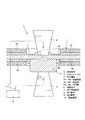
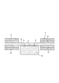
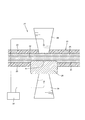
【解決手段】フラットケーブル1に内蔵された平角導体2に対し接続端子6を直交して重ね合わせた後、第1電極8の接点8aを、フラットケーブル1の一方の面に被覆された絶縁被覆3A及び接着剤4Aの一部を除去してなる第一の薄肉部5Aに押し付ける。第2電極9の接点9aを、他方の面に被覆された絶縁被覆3B及び接着剤4Bの一部を除去してなる第二の薄肉部5Bに接続端子6を介して押し付ける。第1電極8と第2電極9との間に通電装置10から供給される電流を通電して、平角導体2と接続端子6との溶接箇所Aを通電可能に抵抗溶接する。ほぼ同時に、少なくとも第二の薄肉部5Bを平角導体2と接続端子6との間から除去する。
【選択図】図3
Description
この発明の導体は、実施例の平角導体2に対応し、
以下同様に、
端子は、接続端子6に対応し、
端子溶接手段は、端子溶接装置7に対応するも、
この発明は、上述の実施形態の構成のみに限定されるものではなく、請求項に示される技術思想に基づいて応用することができ、多くの実施の形態を得ることができる。
L…レーザー
1…フラットケーブル
2…平角導体
3A,3B…絶縁被覆
4A,4B…接着剤
5A,5B…薄肉部
6…接続端子
7…端子溶接装置
8…第1電極
9…第2電極
10…通電装置
Claims (1)
- 絶縁被覆で被覆された導体と、該導体と交差して配置された端子との溶接箇所を一対の端子溶接手段で通電可能に溶接する、フラットケーブルと端子との溶接方法であって、
前記フラットケーブルの一方の面の絶縁被覆に、前記溶接箇所の導体と前記一方の端子溶接手段とが接する部分の絶縁被覆の一部を除去して、前記一方の端子溶接手段が押し付けられる第一の薄肉部を形成し、
前記フラットケーブルの他方の面の絶縁被覆に、前記溶接箇所の導体と前記端子とが交差する部分の絶縁被覆の一部を除去して、前記端子が押し付けられる第二の薄肉部を形成し、
前記一方の端子溶接手段を、前記一方の面の絶縁被覆に形成された第一の薄肉部に押し付け、
前記他方の端子溶接手段を、前記他方の面の絶縁被覆に形成された第二の薄肉部に前記端子を介して押し付け、
前記一対の端子溶接手段によって前記導体と端子との間から第二の薄肉部を除去するとともに、該導体と端子との溶接箇所を通電可能に溶接する
フラットケーブルと端子との溶接方法。
Priority Applications (1)
| Application Number | Priority Date | Filing Date | Title |
|---|---|---|---|
| JP2008258040A JP5203118B2 (ja) | 2008-10-03 | 2008-10-03 | フラットケーブルと端子との溶接方法 |
Applications Claiming Priority (1)
| Application Number | Priority Date | Filing Date | Title |
|---|---|---|---|
| JP2008258040A JP5203118B2 (ja) | 2008-10-03 | 2008-10-03 | フラットケーブルと端子との溶接方法 |
Publications (2)
| Publication Number | Publication Date |
|---|---|
| JP2010086929A true JP2010086929A (ja) | 2010-04-15 |
| JP5203118B2 JP5203118B2 (ja) | 2013-06-05 |
Family
ID=42250671
Family Applications (1)
| Application Number | Title | Priority Date | Filing Date |
|---|---|---|---|
| JP2008258040A Active JP5203118B2 (ja) | 2008-10-03 | 2008-10-03 | フラットケーブルと端子との溶接方法 |
Country Status (1)
| Country | Link |
|---|---|
| JP (1) | JP5203118B2 (ja) |
Cited By (1)
| Publication number | Priority date | Publication date | Assignee | Title |
|---|---|---|---|---|
| WO2011157585A1 (de) * | 2010-06-15 | 2011-12-22 | Robert Bosch Gmbh | Verfahren zur herstellung einer elektrischen verbindung sowie elektrische verbindung |
Citations (2)
| Publication number | Priority date | Publication date | Assignee | Title |
|---|---|---|---|---|
| JP2003045508A (ja) * | 2001-07-31 | 2003-02-14 | Fujikura Ltd | 電源分配回路 |
| JP2003136250A (ja) * | 2001-11-02 | 2003-05-14 | Sumitomo Wiring Syst Ltd | 被覆導電体用抵抗溶接機 |
-
2008
- 2008-10-03 JP JP2008258040A patent/JP5203118B2/ja active Active
Patent Citations (2)
| Publication number | Priority date | Publication date | Assignee | Title |
|---|---|---|---|---|
| JP2003045508A (ja) * | 2001-07-31 | 2003-02-14 | Fujikura Ltd | 電源分配回路 |
| JP2003136250A (ja) * | 2001-11-02 | 2003-05-14 | Sumitomo Wiring Syst Ltd | 被覆導電体用抵抗溶接機 |
Cited By (2)
| Publication number | Priority date | Publication date | Assignee | Title |
|---|---|---|---|---|
| WO2011157585A1 (de) * | 2010-06-15 | 2011-12-22 | Robert Bosch Gmbh | Verfahren zur herstellung einer elektrischen verbindung sowie elektrische verbindung |
| CN102934532A (zh) * | 2010-06-15 | 2013-02-13 | 罗伯特·博世有限公司 | 用于制造电连接结构的方法及电连接结构 |
Also Published As
| Publication number | Publication date |
|---|---|
| JP5203118B2 (ja) | 2013-06-05 |
Similar Documents
| Publication | Publication Date | Title |
|---|---|---|
| EP3672377B1 (en) | Circuit board and using method thereof, battery module and vehicle | |
| CN110770854A (zh) | 线束以及线束的制造方法 | |
| US9711926B2 (en) | Method of forming an interface for an electrical terminal | |
| JP2009043538A (ja) | 超音波接合方法及び超音波接合装置 | |
| JP2015135742A (ja) | 端子および該端子の電線接続方法 | |
| CN107615590B (zh) | 接线端子以及接线端子与电线的接合方法 | |
| JP5989511B2 (ja) | 電線と端子の接続方法 | |
| JP2011113676A (ja) | フレキシブルフラットケーブルに対する端子の接続方法および端子 | |
| JP2013016366A (ja) | 電線導体部の溶接方法、電線およびワイヤハーネス | |
| JP5203118B2 (ja) | フラットケーブルと端子との溶接方法 | |
| CN105309042B (zh) | 感应加热体及感应加热烹调器 | |
| JP4907763B2 (ja) | 平型シールドハーネス及び平型シールドハーネスの製造方法 | |
| CN114080725A (zh) | 配线模块、蓄电模块、汇流条及蓄电模块的制造方法 | |
| WO2015141440A1 (ja) | 端子および該端子の電線接続構造 | |
| JP2009248172A (ja) | 被覆電線の接続方法 | |
| JP5613097B2 (ja) | ヒュージング方法 | |
| JP2002015792A (ja) | フレキシブル基板の端子構造及び接続端子の接合方法 | |
| JP4810679B2 (ja) | コンデンサ | |
| JP5005382B2 (ja) | 電気部材の接続方法 | |
| JP4028160B2 (ja) | フレキシブル基板の端子構造及びその製造方法 | |
| JP5203261B2 (ja) | フラットケーブルと端子との溶接方法及びその溶接装置 | |
| JP3943838B2 (ja) | 金属同士の接合方法 | |
| JP5053023B2 (ja) | フラットケーブルの端子溶接方法及びその端子溶接装置 | |
| JP4747506B2 (ja) | 面状発熱体 | |
| JP4785688B2 (ja) | 電気接続部材 |
Legal Events
| Date | Code | Title | Description |
|---|---|---|---|
| A621 | Written request for application examination |
Free format text: JAPANESE INTERMEDIATE CODE: A621 Effective date: 20110801 |
|
| A977 | Report on retrieval |
Free format text: JAPANESE INTERMEDIATE CODE: A971007 Effective date: 20121015 |
|
| A131 | Notification of reasons for refusal |
Free format text: JAPANESE INTERMEDIATE CODE: A131 Effective date: 20121023 |
|
| A521 | Written amendment |
Free format text: JAPANESE INTERMEDIATE CODE: A523 Effective date: 20121225 |
|
| TRDD | Decision of grant or rejection written | ||
| A01 | Written decision to grant a patent or to grant a registration (utility model) |
Free format text: JAPANESE INTERMEDIATE CODE: A01 Effective date: 20130122 |
|
| A61 | First payment of annual fees (during grant procedure) |
Free format text: JAPANESE INTERMEDIATE CODE: A61 Effective date: 20130213 |
|
| R151 | Written notification of patent or utility model registration |
Ref document number: 5203118 Country of ref document: JP Free format text: JAPANESE INTERMEDIATE CODE: R151 |
|
| FPAY | Renewal fee payment (event date is renewal date of database) |
Free format text: PAYMENT UNTIL: 20160222 Year of fee payment: 3 |
|
| S531 | Written request for registration of change of domicile |
Free format text: JAPANESE INTERMEDIATE CODE: R313531 |
|
| R350 | Written notification of registration of transfer |
Free format text: JAPANESE INTERMEDIATE CODE: R350 |