JP2010084874A - Automatic transmission control device - Google Patents
Automatic transmission control device Download PDFInfo
- Publication number
- JP2010084874A JP2010084874A JP2008255853A JP2008255853A JP2010084874A JP 2010084874 A JP2010084874 A JP 2010084874A JP 2008255853 A JP2008255853 A JP 2008255853A JP 2008255853 A JP2008255853 A JP 2008255853A JP 2010084874 A JP2010084874 A JP 2010084874A
- Authority
- JP
- Japan
- Prior art keywords
- shift
- downshift
- power
- engagement
- pressure
- Prior art date
- Legal status (The legal status is an assumption and is not a legal conclusion. Google has not performed a legal analysis and makes no representation as to the accuracy of the status listed.)
- Granted
Links
Images


Abstract
Description
本発明は、車輌等に搭載される自動変速機の制御装置に係り、詳しくは、ダウンシフト変速時におけるフェール検出を的確に行い得るようにした自動変速機の制御装置に関する。 The present invention relates to a control device for an automatic transmission mounted on a vehicle or the like, and more particularly, to a control device for an automatic transmission that can accurately detect a failure during a downshift.
例えば車輌等に搭載される多段式の自動変速機においては、変速歯車機構の伝達経路を形成するため、変速段に応じて複数(例えば2つ)の摩擦係合要素(クラッチやブレーキ)が係合されるように油圧制御されている。しかしながら、例えばリニアソレノイドバルブの故障(断線やバルブスティック等)により、解放されているはずの摩擦係合要素の油圧サーボに油圧が出力されてしまうと、正常時に係合している摩擦係合要素に加え解放されているはずの摩擦係合要素も同時に係合されてしまう虞がある。 For example, in a multi-stage automatic transmission mounted on a vehicle or the like, a plurality of (for example, two) frictional engagement elements (clutches and brakes) are engaged according to the shift speed in order to form a transmission path of the transmission gear mechanism. It is hydraulically controlled so that However, if the hydraulic pressure is output to the hydraulic servo of the friction engagement element that should have been released due to, for example, a failure of the linear solenoid valve (disconnection, valve stick, etc.), the friction engagement element that is normally engaged In addition, the frictional engagement elements that should have been released may be simultaneously engaged.
そこで、このような同時係合を防止するため、正常時に係合している摩擦係合要素の係合圧を入力した際に、他の摩擦係合要素の油圧(その元圧)を遮断する、いわゆるカットオフバルブを、各変速段において係合する摩擦係合要素の組み合わせに応じて複数本設け、それによって、何れの変速段にあっても同時係合を防止するように構成されたものが提案されている(特許文献1参照)。 Therefore, in order to prevent such simultaneous engagement, when the engagement pressure of the friction engagement element engaged during normal operation is input, the hydraulic pressure (its original pressure) of the other friction engagement elements is shut off. , So-called cutoff valves are provided in accordance with the combination of friction engagement elements that are engaged at each gear stage, thereby preventing simultaneous engagement at any gear stage. Has been proposed (see Patent Document 1).
近年、環境問題等に起因して車輌の燃費向上が求められ、例えば小型車輌等においても自動変速機の多段化が求められており、それによって小型化が求められる自動変速機にあっても、変速段を形成するための摩擦係合要素の数が多数必要となっている。しかし、上記特許文献1に記載の自動変速機の制御装置は、カットオフバルブを用いることによって同時係合を防止するように構成されるため、このようなものを用いると、変速段の増加に応じて該カットオフバルブの本数も多く必要となり、油圧制御装置のコンパクト化を妨げるばかりか、軽量化、コストダウンの妨げにもなってしまう。
In recent years, there has been a demand for improvement in fuel efficiency of vehicles due to environmental problems, etc., for example, there has been a demand for multi-stage automatic transmissions even in small vehicles, etc. A large number of frictional engagement elements are required to form the gear stage. However, since the control device for the automatic transmission described in
そこで、上述のようなカットオフバルブを用いずに同時係合の防止を行い得るように構成した自動変速機の変速制御装置が提案されている(特許文献2参照)。 In view of this, there has been proposed a shift control device for an automatic transmission configured to prevent simultaneous engagement without using a cut-off valve as described above (see Patent Document 2).
該特許文献2に記載の変速制御装置では、自動変速機の変速時においてフェール状態を、「空吹き状態」と「引き摺り状態」のいずれなのかを区別し得るように構成している。つまり、該変速制御装置では、変速中に解放側の摩擦係合要素が解放されない現象、いわゆる引き摺りフェールを、変速中のギヤ比の変化から検出するように構成し、その際のフェールの判断条件として、タイマーによる検出時間が所定時間より大きいか否か、締結(係合)油圧が第1の変速閾値より大きいか否か、ギヤ比の変化が第2の変速閾値より小さいか否かを判定する。これにより、該変速制御装置では、変速比が基準時刻から第2の変速比閾値となることなく第1の変速閾値となるまでに要する時間に基づき第1フェール制御を実行するため、発生しているフェールが空吹き状態なのか引き摺り状態なのかを区別して、フェールの状態に適した制御を行うことが可能となる。
The shift control device described in
しかしながら、上記特許文献2の変速制御装置によると、解放側のフェールか係合側のフェールかを区別して検出することはできるものの、フェールを、シフトダウン変速中におけるものとしては検出することができない場合がある。例えばパワーオンダウン変速時のように回転変化がエンジントルクによって引き起こされる変速については、変速中の係合側への油圧が低いことから、フェール検出における油圧条件を満たすことができない。
However, according to the shift control device of
つまり、摩擦係合要素(クラッチ、ブレーキ)の掴み換えによるシフトダウン変速は、パワーオンダウン(Power On Down)変速とパワーオフダウン(Power Off Down)変速とに大別されるが、パワーオンダウン変速では、イナーシャ相中における回転変化がエンジントルクのみで生じ、ガタ詰め後の待機圧がイナーシャ相中も低くされて変速終了時に係合圧が急上昇するように制御されることから、該待機圧はパワーオフダウン変速時よりも低くされる。このため、上記特許文献2に記載されるようなフェール検出の手法によると、ダウンシフト変速における特にパワーオンダウン変速時のフェール判定を行うことはできない。
In other words, shift-down shifting by changing the friction engagement elements (clutch, brake) is roughly divided into power-on-down and power-off-down shifting. In shifting, the rotation change during the inertia phase occurs only by the engine torque, and the standby pressure after loosening is controlled to be lowered during the inertia phase so that the engagement pressure rapidly increases at the end of the shifting. Is set lower than that during power-off downshifting. For this reason, according to the fail detection method as described in the above-mentioned
そこで本発明は、シフトダウン変速中の、特にパワーオンダウン変速における解放側摩擦係合要素のフェール(解放不良)の判定を高い精度で行うことを可能とする自動変速機の制御装置を提供することを目的とするものである。 Therefore, the present invention provides a control device for an automatic transmission that can perform a determination of a failure (disengagement failure) of a disengagement friction engagement element during a shift-down shift, particularly in a power-on down shift, with high accuracy. It is for the purpose.
請求項1に係る本発明は(例えば図1乃至図10、及び図12参照)、各油圧サーボ(41,42,43,44,45)にそれぞれ供給される係合圧に基づき係合される複数の摩擦係合要素(C−1,C−2,C−3,B−1,B−2)と、駆動源(2)に接続される入力軸(10)と、駆動車輪に接続される出力軸(11)と、を有し、前記複数の摩擦係合要素(C−1,C−2,C−3,B−1,B−2)の係合状態に基づき前記入力軸(10)と前記出力軸(11)との間の伝達経路を変更して複数の変速段を形成すると共に、摩擦係合要素の掴み換え変速を行う自動変速機の制御装置(1)において、
ダウンシフト変速(例えば5→4変速)が開始された際、該ダウンシフト変速はパワーオンダウン変速及びパワーオフダウン変速の何れであるかを判別するダウンシフト判別手段(76)と、
係合側摩擦係合要素(例えばC−1)の油圧サーボ(例えば41)に供給される係合圧を監視する係合圧監視手段(77)と、
前記係合圧がしきい値に達した際に、解放側摩擦係合要素(例えばC−3)の解放不良を判定するフェール判定手段(79)と、を備え、
前記フェール判定手段(79)は、前記ダウンシフト判別手段(76)によって判別されたダウンシフト変速の種類に応じて前記しきい値を変更してなる、
ことを特徴とする自動変速機の制御装置(1)にある。
The present invention according to claim 1 (see, for example, FIGS. 1 to 10 and FIG. 12) is engaged based on the engagement pressure supplied to each hydraulic servo (41, 42, 43, 44, 45). A plurality of friction engagement elements (C-1, C-2, C-3, B-1, B-2), an input shaft (10) connected to the drive source (2), and a drive wheel. Output shaft (11), and based on the engagement state of the plurality of friction engagement elements (C-1, C-2, C-3, B-1, B-2) In the automatic transmission control device (1) for changing the transmission path between the output shaft (10) and the output shaft (11) to form a plurality of shift speeds and for changing the frictional engagement element to change the speed,
Downshift determining means (76) for determining whether the downshift is a power on down shift or a power off down shift when a downshift (for example, 5 → 4 shift) is started;
Engagement pressure monitoring means (77) for monitoring the engagement pressure supplied to the hydraulic servo (for example, 41) of the engagement side frictional engagement element (for example, C-1);
Fail determination means (79) for determining a release failure of the release side frictional engagement element (for example, C-3) when the engagement pressure reaches a threshold value,
The fail determination means (79) changes the threshold according to the type of downshift gear determined by the downshift determination means (76).
The control apparatus (1) for an automatic transmission is characterized by the above.
請求項2に係る本発明は(例えば図1及び図12参照)、前記フェール判定手段(79)は、前記しきい値を、パワーオフダウン変速時に比してパワーオンダウン変速時に低くなるように設定してなる、
請求項1記載の自動変速機の制御装置(1)にある。
According to a second aspect of the present invention (see, for example, FIGS. 1 and 12), the fail determination means (79) lowers the threshold during power-on down shifting compared to during power off down shifting. Set up,
A control device (1) for an automatic transmission according to
請求項3に係る本発明は(例えば図1及び図12参照)、前記ダウンシフト判別手段(76)は、前記駆動源のトルクを所定値と比較し、該所定値より小さいと判定した際にパワーオフダウン変速と判別し、該所定値より大きいと判定した際にパワーオンダウン変速と判別してなる、
請求項1又は2記載の自動変速機の制御装置(1)にある。
According to a third aspect of the present invention (see, for example, FIGS. 1 and 12), the downshift determining means (76) compares the torque of the drive source with a predetermined value and determines that the torque is smaller than the predetermined value. It is determined as a power-off down shift, and when it is determined to be greater than the predetermined value, it is determined as a power on down shift.
It exists in the control apparatus (1) of the automatic transmission of
請求項4に係る本発明は(例えば図1及び図12参照)、前記フェール判定手段(79)により前記解放不良と判定された際、当該ダウンシフト変速を中断して変速開始前の変速段に移行させるフェールアクションを実行してフェールセーフとするフェールセーフ実行手段(80)をさらに備えてなる、
請求項1乃至3の何れか1項記載の自動変速機の制御装置(1)にある。
According to a fourth aspect of the present invention (see, for example, FIGS. 1 and 12), when the failure determination means (79) determines that the release is defective, the downshift is interrupted and the gear before the shift is started. Fail-safe execution means (80) for performing fail-action to be transferred and making it fail-safe is further provided.
A control device (1) for an automatic transmission according to any one of
請求項5に係る本発明は(例えば図1、図6及び図12参照)、前記ダウンシフト判別手段(76)により判別されたダウンシフト変速がパワーオンダウン変速の場合に、前記駆動源(2)の回転が該駆動源(2)の駆動力により上昇するように、前記係合側摩擦係合要素(例えばC−1)の油圧サーボ(例えば41)に供給する係合圧を、イナーシャ相中も低く推移させ、変速終了時に急上昇させる油圧指令手段(71)を備えてなる、
請求項1乃至4の何れか1項記載の自動変速機の制御装置(1)にある。
The present invention according to claim 5 (see, for example, FIGS. 1, 6 and 12), when the downshift determined by the downshift determining means (76) is a power-on downshift, the drive source (2 The engagement pressure supplied to the hydraulic servo (eg 41) of the engagement side frictional engagement element (eg C-1) is adjusted so that the rotation of the drive source (2) is increased by the driving force of the drive source (2). It is provided with a hydraulic command means (71) that makes the inside transition low and suddenly rises at the end of shifting,
The control device (1) for an automatic transmission according to any one of
なお、上記カッコ内の符号は、図面と対照するためのものであるが、これは、発明の理解を容易にするための便宜的なものであり、特許請求の範囲の記載に何等影響を及ぼすものではない。 Note that the reference numerals in the parentheses are for comparison with the drawings, but this is for convenience to facilitate understanding of the invention and has no influence on the description of the claims. It is not a thing.
請求項1に係る本発明によると、ダウンシフト判別手段が、ダウンシフト変速が開始された際、該ダウンシフト変速はパワーオンダウン変速及びパワーオフダウン変速の何れであるかを判別し、係合圧監視手段が、係合側摩擦係合要素の油圧サーボに供給される係合圧を監視し、フェール判定手段が、係合圧がしきい値に達した際に、解放側摩擦係合要素の解放不良を判定すると共に、ダウンシフト判別手段によって判別されたダウンシフト変速の種類に応じてしきい値を変更するので、パワーオフダウン変速とパワーオンダウン変速それぞれの性質に応じたしきい値に基づき、解放側摩擦係合要素の解放不良の判定を、パワーオフダウン変速時は勿論、パワーオンダウン変速時においても高い精度で行うことができる。 According to the first aspect of the present invention, when the downshift is started, the downshift determining means determines whether the downshift is a power-on-down shift or a power-off-down shift, and is engaged. The pressure monitoring means monitors the engagement pressure supplied to the hydraulic servo of the engagement side frictional engagement element, and when the failure determination means reaches the threshold value, the release side frictional engagement element Since the threshold value is changed according to the type of downshift transmission determined by the downshift determination means, the threshold value according to the characteristics of the power-off downshift and the power-ondownshift is determined. Based on the above, it is possible to determine the release failure of the disengagement side frictional engagement element with high accuracy not only during the power-off downshift but also during the power-on downshift.
請求項2に係る本発明によると、フェール判定手段が、しきい値を、パワーオフダウン変速時に比してパワーオンダウン変速時に低くなるように設定するので、ダウンシフト変速の種類に応じて油圧判定条件を適切に切り分け、ダウンシフト変速中での解放側摩擦係合要素の解放不良の判定を、高い精度で行うことができる。従って、係合側摩擦係合要素のガタ詰め後の待機圧が変速終期まで低い圧に保たれているパワーオンダウン変速にあっても、解放不良の判定を極めて正確に行うことができる。 According to the second aspect of the present invention, the fail determination means sets the threshold value to be lower at the power-on down shift than at the power off down shift. The determination conditions can be appropriately divided, and the determination of the release failure of the release side frictional engagement element during the downshift can be performed with high accuracy. Therefore, even in a power-on down shift in which the standby pressure after loosening of the engagement-side frictional engagement element is kept at a low pressure until the end of the shift, it is possible to determine the release failure extremely accurately.
請求項3に係る本発明によると、ダウンシフト判別手段が、駆動源トルクを所定値と比較し、該所定値より小さいと判定した際にパワーオフダウン変速と判別し、該所定値より大きいと判定した際にパワーオンダウン変速と判別するので、ダウンシフト変速であっても、駆動源トルクが所定値より大きい(正トルク等)場合は、係合側摩擦係合要素の係合に拘わらず駆動源トルクで回転変化を起こし得るパワーオンダウンと判別することができ、また、駆動源トルクが所定値より小さい(負トルク等)場合は、駆動源トルクによっては回転変化の起こり難いパワーオフダウンと判別することができる。 According to the third aspect of the present invention, when the downshift determining means compares the driving source torque with a predetermined value and determines that it is smaller than the predetermined value, it determines that it is a power-off downshift, and if it is larger than the predetermined value. When the determination is made, it is determined that the power-on downshift is performed. Therefore, even when the downshift is performed, if the drive source torque is larger than a predetermined value (eg, positive torque), the engagement side frictional engagement element is engaged. It can be determined that the power on / down can cause a rotation change due to the drive source torque, and if the drive source torque is smaller than a predetermined value (such as negative torque), the power off / down where the rotation change hardly occurs depending on the drive source torque. Can be determined.
請求項4に係る本発明によると、フェールセーフ実行手段が、フェール判定手段により解放不良と判定された際、当該ダウンシフト変速を中断して変速開始前の変速段に移行させるフェールアクションを実行してフェールセーフとするので、解放不良と判定された解放側摩擦係合要素を使用しない変速段、つまり変速開始前の変速段に戻すことで、走行上問題の無い変速段による走行を続けることができる。 According to the fourth aspect of the present invention, when the fail safe execution unit determines that the release is poor by the fail determination unit, the fail safe execution unit executes a fail action that interrupts the downshift and shifts to the shift stage before the start of the shift. Therefore, it is possible to continue traveling at a gear position that does not cause a problem in traveling by returning to a gear position that does not use the disengagement-side frictional engagement element determined to be defective, that is, a gear position before the start of gear shifting. it can.
請求項5に係る本発明によると、油圧指令手段が、ダウンシフト判別手段により判別されたダウンシフト変速がパワーオンダウン変速の場合に、駆動源の回転が該駆動源の駆動力により上昇するように、係合側摩擦係合要素の油圧サーボに供給する係合圧を、イナーシャ相中も低く推移させ、変速終了時に急上昇させるので、パワーオンダウン変速時の変速段形成上の性質に応じて、適切に油圧制御することができる。 According to the fifth aspect of the present invention, when the downshift determined by the downshift determining unit is a power-on downshift, the hydraulic pressure commanding unit increases the rotation of the driving source by the driving force of the driving source. In addition, the engagement pressure supplied to the hydraulic servo of the engagement side frictional engagement element is kept low during the inertia phase and suddenly rises at the end of the shift. Can be properly hydraulically controlled.
以下、本発明に係る実施の形態を図1乃至図12に沿って説明する。 Embodiments according to the present invention will be described below with reference to FIGS.
[自動変速機の概略構成]
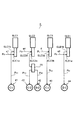
まず、本発明を適用し得る自動変速機3の概略構成について図2に沿って説明する。図2に示すように、例えばFFタイプ(フロントエンジン、フロントドライブ)の車輌に用いて好適な自動変速機3は、エンジン(駆動源)2(図1参照)に接続し得る自動変速機3の入力軸8を有しており、該入力軸8の軸方向を中心としてトルクコンバータ4と、自動変速機構5とを備えている。
[Schematic configuration of automatic transmission]
First, a schematic configuration of an
上記トルクコンバータ4は、自動変速機3の入力軸8に接続されたポンプインペラ4aと、作動流体を介して該ポンプインペラ4aの回転が伝達されるタービンランナ4bとを有しており、該タービンランナ4bは、上記入力軸8と同軸上に配設された上記自動変速機構5の入力軸10に接続されている。また、該トルクコンバータ4には、ロックアップクラッチ7が備えられており、該ロックアップクラッチ7が係合されると、上記自動変速機3の入力軸8の回転が自動変速機構5の入力軸10に直接伝達される。
The
上記自動変速機構5は、各油圧サーボ41〜45(図5参照)にそれぞれ供給される係合圧に基づき係合されるクラッチC−1,C−2,C−3、ブレーキB−1,B−2と、エンジン2に接続される入力軸10と、不図示の駆動車輪に接続されるカウンタギヤ11とを有して、上記クラッチC−1,C−2,C−3、ブレーキB−1,B−2の係合状態に基づき入力軸10とカウンタギヤ11との間の伝達経路を変更して複数の変速段を形成するものであり、該自動変速機構5には、入力軸10上において、プラネタリギヤSPと、プラネタリギヤユニットPUとが備えられている。上記プラネタリギヤSPは、サンギヤS1、キャリヤCR1、及びリングギヤR1を備えており、該キャリヤCR1に、サンギヤS1及びリングギヤR1に噛合するピニオンP1を有している、いわゆるシングルピニオンプラネタリギヤである。
The
また、該プラネタリギヤユニットPUは、4つの回転要素としてサンギヤS2、サンギヤS3、キャリヤCR2、及びリングギヤR2を有し、該キャリヤCR2に、サンギヤS2及びリングギヤR2に噛合するロングピニオンPLと、サンギヤS3に噛合するショートピニオンPSとを互いに噛合する形で有している、いわゆるラビニヨ型プラネタリギヤである。 The planetary gear unit PU has a sun gear S2, a sun gear S3, a carrier CR2, and a ring gear R2 as four rotating elements. The long gearion PL that meshes with the sun gear S2 and the ring gear R2 and the sun gear S3 This is a so-called Ravigneaux type planetary gear that has meshing short pinions PS that mesh with each other.
上記プラネタリギヤSPのサンギヤS1は、ミッションケース9に一体的に固定されているボス部に接続されて回転が固定されている。また、上記リングギヤR1は、上記入力軸10の回転と同回転(以下「入力回転」という。)になっている。さらに上記キャリヤCR1は、該固定されたサンギヤS1と該入力回転するリングギヤR1とにより、入力回転が減速された減速回転になると共に、クラッチ(摩擦係合要素)C−1及びクラッチ(摩擦係合要素)C−3に接続されている。
The sun gear S <b> 1 of the planetary gear SP is connected to a boss portion that is integrally fixed to the
上記プラネタリギヤユニットPUのサンギヤS2は、バンドブレーキからなるブレーキB−1に接続されてミッションケースに対して固定自在となっていると共に、上記クラッチC−3に接続され、該クラッチC−3を介して上記キャリヤCR1の減速回転が入力自在となっている。また、上記サンギヤS3は、クラッチC−1に接続されており、上記キャリヤCR1の減速回転が入力自在となっている。なお、該ブレーキB−1は、クラッチC−3及びサンギヤS2に連結されたドラム状部材18に周設されたブレーキバンド19を有してなり、該ブレーキバンド19は、一端がケース9に固定され、他端が後述する油圧サーボ44(図5参照)に駆動連結されて、該油圧サーボ44の駆動により該ドラム状部材18に巻付けられるように構成されている。このブレーキバンド19の巻付け方向は、前進2速段から前進6速段におけるドラム状部材18の回転方向と逆方向になるように配設され、つまり油圧サーボ44によってドラム状部材18の前進2速段から前進6速段における回転方向に対して逆方向に引っ張って巻付けを行うように構成されている。
The sun gear S2 of the planetary gear unit PU is connected to a brake B-1 formed of a band brake so as to be freely fixed to the transmission case, and is connected to the clutch C-3 via the clutch C-3. Thus, the decelerated rotation of the carrier CR1 can be input. The sun gear S3 is connected to the clutch C-1, so that the decelerated rotation of the carrier CR1 can be input. The brake B-1 has a
さらに、上記キャリヤCR2は、入力軸10の回転が入力されるクラッチC−2に接続され、該クラッチC−2を介して入力回転が入力自在となっており、また、ワンウェイクラッチF−1及びブレーキB−2に接続されて、該ワンウェイクラッチF−1を介してミッションケースに対して一方向の回転が規制されると共に、該ブレーキB−2を介して回転が固定自在となっている。そして、上記リングギヤR2は、カウンタギヤ(出力軸)11に接続されており、該カウンタギヤ11は、不図示のカウンタシャフト、ディファレンシャル装置を介して不図示の駆動車輪に接続されている。
Further, the carrier CR2 is connected to a clutch C-2 to which the rotation of the
[自動変速機における各変速段の動作]
つづいて、上記構成に基づき、自動変速機構5の作用について図2、図3及び図4に沿って説明する。なお、図4に示す速度線図において、縦軸方向はそれぞれの回転要素(各ギヤ)の回転数を示しており、横軸方向はそれら回転要素のギヤ比に対応して示している。また、該速度線図のプラネタリギヤSPの部分において、縦軸は、図4中左方側から順に、サンギヤS1、キャリヤCR1、リングギヤR1に対応している。さらに、該速度線図のプラネタリギヤユニットPUの部分において、縦軸は、図4中右方側から順に、サンギヤS3、リングギヤR2、キャリヤCR2、サンギヤS2に対応している。
[Operation of each gear stage in automatic transmission]
Next, based on the above configuration, the operation of the
例えばD(ドライブ)レンジであって、前進1速段(1ST)では、図3に示すように、クラッチC−1及びワンウェイクラッチF−1が係合される。すると、図2及び図4に示すように、固定されたサンギヤS1と入力回転であるリングギヤR1によって減速回転するキャリヤCR1の回転が、クラッチC−1を介してサンギヤS3に入力される。また、キャリヤCR2の回転が一方向(正転回転方向)に規制されて、つまりキャリヤCR2の逆転回転が防止されて固定された状態になる。すると、サンギヤS3に入力された減速回転が、固定されたキャリヤCR2を介してリングギヤR2に出力され、前進1速段としての正転回転がカウンタギヤ11から出力される。
For example, in the D (drive) range and the first forward speed (1ST), as shown in FIG. 3, the clutch C-1 and the one-way clutch F-1 are engaged. Then, as shown in FIGS. 2 and 4, the rotation of the carrier CR1 that is decelerated by the fixed sun gear S1 and the ring gear R1 that is the input rotation is input to the sun gear S3 via the clutch C-1. Further, the rotation of the carrier CR2 is restricted in one direction (forward rotation direction), that is, the carrier CR2 is prevented from rotating in the reverse direction and is fixed. Then, the decelerated rotation input to the sun gear S3 is output to the ring gear R2 via the fixed carrier CR2, and the forward rotation as the first forward speed is output from the
なお、エンジンブレーキ時(コースト時)には、ブレーキB−2を係止してキャリヤCR2を固定し、該キャリヤCR2の正転回転を防止する形で、上記前進1速段の状態を維持する。また、該前進1速段では、ワンウェイクラッチF−1によりキャリヤCR2の逆転回転を防止し、かつ正転回転を可能にするので、例えば非走行レンジから走行レンジに切換えた際の前進1速段の達成を、ワンウェイクラッチF−1の自動係合により滑らかに行うことができる。 During engine braking (coast), the brake B-2 is locked to fix the carrier CR2, and the forward first speed state is maintained by preventing the carrier CR2 from rotating forward. . Further, at the first forward speed, the one-way clutch F-1 prevents the carrier CR2 from rotating in the reverse direction and enables forward rotation, so that the first forward speed when switching from the non-traveling range to the traveling range, for example. Can be smoothly achieved by the automatic engagement of the one-way clutch F-1.
前進2速段(2ND)では、図3に示すように、クラッチC−1が係合され、ブレーキB−1が係止される。すると、図2及び図4に示すように、固定されたサンギヤS1と入力回転であるリングギヤR1によって減速回転するキャリヤCR1の回転が、クラッチC−1を介してサンギヤS3に入力される。また、ブレーキB−1の係止によりサンギヤS2の回転が固定される。すると、キャリヤCR2がサンギヤS3よりも低回転の減速回転となり、該サンギヤS3に入力された減速回転が該キャリヤCR2を介してリングギヤR2に出力され、前進2速段としての正転回転がカウンタギヤ11から出力される。 At the second forward speed (2ND), as shown in FIG. 3, the clutch C-1 is engaged and the brake B-1 is locked. Then, as shown in FIGS. 2 and 4, the rotation of the carrier CR1 that is decelerated by the fixed sun gear S1 and the ring gear R1 that is the input rotation is input to the sun gear S3 via the clutch C-1. Further, the rotation of the sun gear S2 is fixed by the locking of the brake B-1. Then, the carrier CR2 is decelerated and rotated at a speed lower than that of the sun gear S3, the decelerated rotation input to the sun gear S3 is output to the ring gear R2 via the carrier CR2, and the forward rotation as the second forward speed is counter gear. 11 is output.
前進3速段(3RD)では、図3に示すように、クラッチC−1及びクラッチC−3が係合される。すると、図2及び図4に示すように、固定されたサンギヤS1と入力回転であるリングギヤR1によって減速回転するキャリヤCR1の回転が、クラッチC−1を介してサンギヤS3に入力される。また、クラッチC−3の係合によりキャリヤCR1の減速回転がサンギヤS2に入力される。つまり、サンギヤS2及びサンギヤS3にキャリヤCR1の減速回転が入力されるため、プラネタリギヤユニットPUが減速回転の直結状態となり、そのまま減速回転がリングギヤR2に出力され、前進3速段としての正転回転がカウンタギヤ11から出力される。
In the third forward speed (3RD), as shown in FIG. 3, the clutch C-1 and the clutch C-3 are engaged. Then, as shown in FIGS. 2 and 4, the rotation of the carrier CR1 that is decelerated by the fixed sun gear S1 and the ring gear R1 that is the input rotation is input to the sun gear S3 via the clutch C-1. Further, the reduced rotation of the carrier CR1 is input to the sun gear S2 by the engagement of the clutch C-3. That is, since the reduction rotation of the carrier CR1 is input to the sun gear S2 and the sun gear S3, the planetary gear unit PU is directly connected to the reduction rotation, and the reduction rotation is output to the ring gear R2 as it is, and the forward rotation as the third forward speed is performed. Output from the
前進4速段(4TH)では、図3に示すように、クラッチC−1及びクラッチC−2が係合される。すると、図2及び図4に示すように、固定されたサンギヤS1と入力回転であるリングギヤR1によって減速回転するキャリヤCR1の回転が、クラッチC−1を介してサンギヤS3に入力される。また、クラッチC−2に係合によりキャリヤCR2に入力回転が入力される。すると、該サンギヤS3に入力された減速回転とキャリヤCR2に入力された入力回転とにより、上記前進3速段より高い減速回転となってリングギヤR2に出力され、前進4速段としての正転回転がカウンタギヤ11から出力される。
At the fourth forward speed (4TH), as shown in FIG. 3, the clutch C-1 and the clutch C-2 are engaged. Then, as shown in FIGS. 2 and 4, the rotation of the carrier CR1 that is decelerated by the fixed sun gear S1 and the ring gear R1 that is the input rotation is input to the sun gear S3 via the clutch C-1. Further, the input rotation is input to the carrier CR2 by engaging the clutch C-2. Then, due to the decelerated rotation input to the sun gear S3 and the input rotation input to the carrier CR2, the decelerated rotation is higher than the third forward speed and is output to the ring gear R2, and the forward rotation as the fourth forward speed is performed. Is output from the
前進5速段(5TH)では、図3に示すように、クラッチC−2及びクラッチC−3が係合される。すると、図2及び図4に示すように、固定されたサンギヤS1と入力回転であるリングギヤR1によって減速回転するキャリヤCR1の回転が、クラッチC−3を介してサンギヤS2に入力される。また、クラッチC−2の係合によりキャリヤCR2に入力回転が入力される。すると、該サンギヤS2に入力された減速回転とキャリヤCR2に入力された入力回転とにより、入力回転より僅かに高い増速回転となってリングギヤR2に出力され、前進5速段としての正転回転がカウンタギヤ11から出力される。
At the fifth forward speed (5TH), as shown in FIG. 3, the clutch C-2 and the clutch C-3 are engaged. Then, as shown in FIGS. 2 and 4, the rotation of the carrier CR1 that is decelerated and rotated by the fixed sun gear S1 and the ring gear R1 that is the input rotation is input to the sun gear S2 via the clutch C-3. Further, the input rotation is input to the carrier CR2 by the engagement of the clutch C-2. Then, due to the decelerated rotation input to the sun gear S2 and the input rotation input to the carrier CR2, the rotation speed is slightly higher than the input rotation and is output to the ring gear R2, which is the forward rotation as the fifth forward speed. Is output from the
前進6速段(6TH)では、図3に示すように、クラッチC−2が係合され、ブレーキB−1が係止される。すると、図2及び図4に示すように、クラッチC−2の係合によりキャリヤCR2に入力回転が入力される。また、ブレーキB−1の係止によりサンギヤS2の回転が固定される。すると、固定されたサンギヤS2によりキャリヤCR2の入力回転が上記前進5速段より高い増速回転となってリングギヤR2に出力され、前進6速段としての正転回転がカウンタギヤ11から出力される。
At the sixth forward speed (6TH), as shown in FIG. 3, the clutch C-2 is engaged and the brake B-1 is locked. Then, as shown in FIGS. 2 and 4, the input rotation is input to the carrier CR2 by the engagement of the clutch C-2. Further, the rotation of the sun gear S2 is fixed by the locking of the brake B-1. Then, the input rotation of the carrier CR2 becomes higher than the forward fifth speed by the fixed sun gear S2, and is output to the ring gear R2, and the forward rotation as the sixth forward speed is output from the
後進1速段(REV)では、図3に示すように、クラッチC−3が係合され、ブレーキB−2が係止される。すると、図2及び図4に示すように、固定されたサンギヤS1と入力回転であるリングギヤR1によって減速回転するキャリヤCR1の回転が、クラッチC−3を介してサンギヤS2に入力される。また、ブレーキB−2の係止によりキャリヤCR2の回転が固定される。すると、サンギヤS2に入力された減速回転が、固定されたキャリヤCR2を介してリングギヤR2に出力され、後進1速段としての逆転回転がカウンタギヤ11から出力される。
In the first reverse speed (REV), as shown in FIG. 3, the clutch C-3 is engaged and the brake B-2 is locked. Then, as shown in FIGS. 2 and 4, the rotation of the carrier CR1 that is decelerated and rotated by the fixed sun gear S1 and the ring gear R1 that is the input rotation is input to the sun gear S2 via the clutch C-3. Further, the rotation of the carrier CR2 is fixed by the locking of the brake B-2. Then, the decelerated rotation input to the sun gear S2 is output to the ring gear R2 via the fixed carrier CR2, and the reverse rotation as the first reverse speed is output from the
なお、例えばP(パーキング)レンジ及びN(ニュートラル)レンジでは、クラッチC−1、クラッチC−2、及びクラッチC−3、が解放される。すると、キャリヤCR1とサンギヤS2及びサンギヤS3との間、即ちプラネタリギヤSPとプラネタリギヤユニットPUとの間が切断状態となり、かつ、入力軸10とキャリヤCR2との間が切断状態となる。これにより、入力軸10とプラネタリギヤユニットPUとの間の動力伝達が切断状態となり、つまり入力軸10とカウンタギヤ11との動力伝達が切断状態となる。
For example, in the P (parking) range and the N (neutral) range, the clutch C-1, the clutch C-2, and the clutch C-3 are released. Then, the carrier CR1, the sun gear S2, and the sun gear S3, that is, the planetary gear SP and the planetary gear unit PU are disconnected, and the
[油圧制御装置の概略構成]
つづいて、本発明に係る自動変速機の油圧制御装置6について説明する。まず、油圧制御装置6(図1参照)における図示を省略した、ライン圧、セカンダリ圧、モジュレータ圧、レンジ圧等の生成部分について、大まかに説明する。なお、これらライン圧、セカンダリ圧、モジュレータ圧、レンジ圧の生成部分は、一般的な自動変速機の油圧制御装置と同様なものであり、周知のものであるので、簡単に説明する。
[Schematic configuration of hydraulic control unit]
Next, the hydraulic control device 6 for an automatic transmission according to the present invention will be described. First, generation parts such as a line pressure, a secondary pressure, a modulator pressure, and a range pressure, which are not shown in the hydraulic control device 6 (see FIG. 1), will be roughly described. The generation portions of the line pressure, secondary pressure, modulator pressure, and range pressure are the same as those of a general automatic transmission hydraulic control device, and are well-known and will be described briefly.
本油圧制御装置6は、例えば図示を省略したオイルポンプ、マニュアルシフトバルブ、プライマリレギュレータバルブ、セカンダリレギュレータバルブ、ソレノイドモジュレータバルブ及びリニアソレノイドバルブSLT等を備えており、例えばエンジン2(図1参照)が始動されると、上記トルクコンバータ4のポンプインペラ4aに回転駆動連結されたオイルポンプがエンジン2の回転に連動して駆動されることにより、不図示のオイルパンからストレーナを介してオイルを吸上げる形で油圧を発生させる。
The hydraulic control device 6 includes, for example, an oil pump, a manual shift valve, a primary regulator valve, a secondary regulator valve, a solenoid modulator valve, a linear solenoid valve SLT, and the like (not shown). For example, the engine 2 (see FIG. 1) When started, the oil pump that is rotationally connected to the
上記オイルポンプにより発生された油圧は、スロットル開度に応じて調圧出力されるリニアソレノイドバルブSLTの信号圧PSLTに基づき、プライマリレギュレータバルブによって排出調整されつつライン圧PLに調圧される。このライン圧PLは、マニュアルシフトバルブ、ソレノイドモジュレータバルブ、及び詳しくは後述するリニアソレノイドバルブSLC3等に供給される。このうちのソレノイドモジュレータバルブに供給されたライン圧PLは、該バルブによって略々一定圧となるモジュレータ圧PMODに調圧され、このモジュレータ圧PMODは、上記リニアソレノイドバルブSLT等の元圧として供給される。 Hydraulic pressure generated by the oil pump, on the basis of a signal pressure P SLT of the linear solenoid valve SLT that is pressure regulating output according to the throttle opening degree, the pressure is adjusted to a line pressure P L being discharged adjusted by the primary regulator valve . The line pressure P L is the manual shift valve, the solenoid modulator valve, and more information is supplied to the linear solenoid valve SLC3 to be described later. The line pressure P L supplied to the solenoid modulator valve of this is pressure regulated to a modulator pressure P MOD to be substantially constant pressure by the valve, the modulator pressure P MOD is the original pressure, such as the linear solenoid valve SLT Supplied as
なお、上記プライマリレギュレータバルブから排出された圧は、例えばセカンダリレギュレータバルブによりさらに排出調整されつつセカンダリ圧PSECに調圧され、このセカンダリ圧PSECが、例えば潤滑油路やオイルクーラ等に供給されると共にトルクコンバータ4にも供給され、かつロックアップクラッチ7の制御にも用いられる。
The pressure discharged from the primary regulator valve is adjusted to the secondary pressure PSEC while being further discharged and adjusted by, for example, the secondary regulator valve, and this secondary pressure PSEC is supplied to, for example, a lubricating oil passage or an oil cooler. And also supplied to the
一方、マニュアルシフトバルブ(不図示)は、運転席(不図示)に設けられたシフトレバーに機械的(或いは電気的)に駆動されるスプールを有しており、該スプールの位置がシフトレバーにより選択されたシフトレンジ(例えばP,R,N,D)に応じて切換えられることにより、上記入力されたライン圧PLの出力状態や非出力状態(ドレーン)を設定する。 On the other hand, a manual shift valve (not shown) has a spool that is mechanically (or electrically) driven by a shift lever provided in a driver's seat (not shown), and the position of the spool is controlled by the shift lever. selected shift range (e.g. P, R, N, D) by being switched according to, to set the output state or non-output state of the line pressure P L the input (drain).
詳細には、シフトレバーの操作に基づきDレンジにされると、上記スプールの位置に基づき上記ライン圧PLが入力される入力ポートと前進レンジ圧出力ポートとが連通し、該前進レンジ圧出力ポートよりライン圧PLが前進レンジ圧(Dレンジ圧)PDとして出力される。シフトレバーの操作に基づきR(リバース)レンジにされると、該スプールの位置に基づき上記入力ポートと後進レンジ圧出力ポートとが連通し、該後進レンジ圧出力ポートよりライン圧PLが後進レンジ圧(Rレンジ圧)PREVとして出力される。また、シフトレバーの操作に基づきPレンジ及びNレンジにされた際は、上記入力ポートと前進レンジ圧出力ポート及び後進レンジ圧出力ポートとの間がスプールによって遮断されると共に、それら前進レンジ圧出力ポート及び後進レンジ圧出力ポートがドレーンポートに連通され、つまりDレンジ圧PD及びRレンジ圧PREVがドレーン(排出)された非出力状態となる。 In particular, when the D range based on the operation of the shift lever, through said line pressure P L is communicated with the input port to be input and a forward range pressure output port based on the position of the spool, the forward range pressure output line from the port pressure P L is output as a forward range pressure (D range pressure) P D. When based on the operation of the shift lever to the R (reverse) range, communicates with the input port and the reverse range pressure output port based on the position of the spool, the line pressure P L rear proceeds range pressure output port reverse range Pressure (R range pressure) PREV is output. Further, when the P range and the N range are set based on the operation of the shift lever, the input port, the forward range pressure output port and the reverse range pressure output port are blocked by the spool, and the forward range pressure output. port and the reverse range pressure output port are communicated with the drain port, that is, the non-output state D range pressure P D and the R range pressure P REV are drained (discharged).
[油圧制御装置における変速制御部分の構成]
ついで、本発明に係る油圧制御装置6における主に変速制御を行う部分について図5に沿って説明する。図5は、本自動変速機の油圧制御装置6を、抜粋して概略的に示す回路図である。本実施の形態では、従来のようなカットオフバルブを用いることなく、ストール状態の発生をソフト的に防止することを可能とし、3つの係合要素が同時係合してしまった場合そのうちの1係合要素を引き摺るようにしてストール状態を回避するが、3係合要素の同時係合はできる限り行わないことが望ましく、従って、変速中にフェール(解放側摩擦係合要素の解放不良)の有無を早い段階で検出し得るように構成すると共に、解放不良の判定時にはフェールアクションを実施するように構成している。
[Configuration of shift control portion in hydraulic control device]
Next, a portion that mainly performs shift control in the hydraulic control device 6 according to the present invention will be described with reference to FIG. FIG. 5 is a circuit diagram schematically showing an excerpt of the hydraulic control device 6 of the automatic transmission. In the present embodiment, it is possible to prevent the occurrence of a stall state without using a cut-off valve as in the prior art, and one of the three engaging elements is simultaneously engaged. It is desirable to avoid the stall state by dragging the engaging elements, but it is desirable that the three engaging elements are not simultaneously engaged as much as possible. It is configured so that presence / absence can be detected at an early stage, and a fail action is performed when a release failure is determined.
本油圧制御装置6は、上述のクラッチC−1の油圧サーボ41、クラッチC−2の油圧サーボ42、クラッチC−3の油圧サーボ43、ブレーキB−1の油圧サーボ44、ブレーキB−2の油圧サーボ45の、計5つの油圧サーボのそれぞれに係合圧として調圧した出力圧を直接的に供給するための4本のリニアソレノイドバルブSLC1,SLC2,SLC3,SLB1を備えている。また、リンプホーム機能を達成すると共に、リニアソレノイドバルブSLC2の出力圧をクラッチC−2の油圧サーボ42又はブレーキB−2の油圧サーボ45に切換える切換えバルブ23を備えている。なお、該切換えバルブ23は、実際には単体のバルブではなく、不図示のソレノイドバルブ、第1クラッチアプライリレーバルブ、第2クラッチアプライリレーバルブ、C−2リレーバルブ、B−2リレーバルブ等を集約した形で描いている。
The hydraulic control device 6 includes the
リニアソレノイドバルブSLC1への油路a1、リニアソレノイドバルブSLC2への油路a4、リニアソレノイドバルブSLB1への油路a5には、上述したマニュアルシフトバルブの前進レンジ圧出力ポート(不図示)が接続されて前進レンジ圧PDが入力し得るように構成されており、また、リニアソレノイドバルブSLC3への油路dには、プライマリレギュレータバルブ(不図示)からのライン圧PLが入力されている。 A forward range pressure output port (not shown) of the manual shift valve described above is connected to the oil passage a1 to the linear solenoid valve SLC1, the oil passage a4 to the linear solenoid valve SLC2, and the oil passage a5 to the linear solenoid valve SLB1. is configured to forward range pressure P D can be input Te, in addition, the oil passage d to the linear solenoid valve SLC3, the line pressure P L from the primary regulator valve (not shown) is input.
上記リニアソレノイドバルブSLC1は、非通電時に非出力状態となるノーマルクローズタイプからなり、油路a1を介して上記前進レンジ圧PDを入力する入力ポートSLC1aと、該前進レンジ圧PDを調圧して油圧サーボ41に制御圧PSLC1を係合圧PC1として出力する出力ポートSLC1bとを有している。
The linear solenoid valve SLC1 is of a normally closed type that when not energized in a non-output state, the input port SLC1a for receiving the forward range pressure P D via the oil path a1, by regulating the forward range pressure P D and an output port SLC1b for outputting as the engagement pressure P C1 control pressure P SLC1 to the
上記リニアソレノイドバルブSLC2は、非通電時に出力状態となるノーマルオープンタイプからなり、油路a4を介して上記前進レンジ圧PDを入力する入力ポートSLC2aと、該前進レンジ圧PDを調圧して油圧サーボ42に制御圧PSLC2を係合圧PC2(又は係合圧PB2)として出力する出力ポートSLC2bとを有している。
The linear solenoid valve SLC2 is a normally open type that attains an outputting state when being de-energized, the input port SLC2a for receiving the forward range pressure P D via the oil path a4, and by regulating the forward range pressure P D The
上記リニアソレノイドバルブSLC3は、非通電時に出力状態となるノーマルオープンタイプからなり、油路dを介して上記ライン圧PLを入力する入力ポートSLC3aと、該ライン圧PLを調圧して油圧サーボ43に制御圧PSLC3を係合圧PC3として出力する出力ポートSLC3bとを有している。 The linear solenoid valve SLC3 is a normally open type that attains an outputting state when not energized, the input port SLC3a which inputs the line pressure P L via the oil passage d, the hydraulic servo by regulating the line pressure P L and an output port SLC3b for outputting a control pressure P SLC3 as the engagement pressure P C3 to 43.
上記リニアソレノイドバルブSLB1は、非通電時に非出力状態となるノーマルクローズタイプからなり、油路a5を介して上記前進レンジ圧PDを入力する入力ポートSLB1aと、該前進レンジ圧PDを調圧して油圧サーボ44に制御圧PSLB1を係合圧PB1として出力する出力ポートSLB1bとを有している。 The linear solenoid valve SLB1 is of a normally closed type that when not energized in a non-output state, the input port SLB1a for receiving the forward range pressure P D through the oil passage a5, by regulating the forward range pressure P D and an output port SLB1b to output as the engagement pressure P B1 control pressure P SLB1 to the hydraulic servo 44 Te.
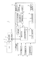
つづいて、本発明に係る自動変速機の制御装置1について、主に図1に沿って説明する。
Next, the
図1に示すように、本自動変速機の制御装置1は、制御部(ECU)70を有しており、該制御部70は、アクセル開度センサ81、入力軸回転数センサ83、出力軸回転数(車速)センサ82などが接続されていると共に、上述した油圧制御装置6の各リニアソレノイドバルブSLC1,SLC2,SLC3,SLB1などに接続されている。また、該制御部70には、エンジン2からエンジン回転数信号とエンジントルク信号が送られる。そして、該制御部70には、正常時油圧設定手段72を有する油圧指令手段71、入力トルク検出手段73、トルク分担判定手段74、変速判定手段75、及び変速マップmapが備えられている。さらに、制御部70には、変速進行率算出手段78、ダウンシフト判別手段76、係合圧監視手段77、フェール判定手段79、及びフェールセーフ実行手段80が備えられている。
As shown in FIG. 1, the
上記変速判定手段75は、アクセル開度センサ81により検出されるアクセル開度と、出力軸回転数センサ82により検出される車速とに基づき変速マップmapを参照しつつ、上述の前進1速段〜前進6速段を判定する。即ち、変速マップmapには、アクセル開度と車速とに対応したアップシフト変速線及びダウンシフト変速線(変速点)が記録されており、その時点のアクセル開度及び車速がそれら変速線を越えると、変速判定手段75が変速を判断する。そして、該変速判定手段75が判定した変速段(現在の変速段)は、油圧指令手段71及びトルク分担判定手段74に出力される。
The shift determination means 75 refers to the shift map map based on the accelerator opening detected by the
一方、入力トルク検出手段73は、エンジン2からのエンジントルク信号を入力することで、エンジントルクを計測し、現在自動変速機構5の入力軸10に入力されている入力トルクを検出する。また、上記トルク分担判定手段74は、上記変速判定手段75により判定された変速段に基づき、自動変速機構5において係合されているクラッチやブレーキ(図3参照)におけるトルク分担、即ち各ギヤ比に基づきクラッチやブレーキにおいて必要とされる上記入力トルクに対する比率を判定(算出)する。
On the other hand, the input torque detection means 73 inputs an engine torque signal from the
ついで、正常時油圧設定手段72は、上記トルク分担判定手段74により判定された、変速段に応じて係合中のクラッチやブレーキにおけるトルク分担に安全率(例えば1.3倍)を掛け、さらに、その安全率を掛けたトルク分担の値と入力トルク検出手段73により検出された入力トルクとを掛けて係合中のクラッチやブレーキのトルク容量(伝達トルク)を算出し、各クラッチやブレーキの摩擦板の枚数、面積、油圧サーボの受圧面積などから、それら係合中のクラッチやブレーキの油圧サーボに供給する係合圧(制御圧)を算出する。 Next, the normal time hydraulic pressure setting means 72 multiplies the torque sharing in the engaged clutch or brake determined by the torque sharing determination means 74 according to the gear position, by multiplying the safety factor (eg, 1.3 times), and The torque sharing value multiplied by the safety factor is multiplied by the input torque detected by the input torque detecting means 73 to calculate the torque capacity (transmission torque) of the clutch or brake being engaged, From the number of friction plates, the area, the pressure receiving area of the hydraulic servo, and the like, the engagement pressure (control pressure) to be supplied to the hydraulic servo of the clutch or brake being engaged is calculated.
そして、油圧指令手段71は、上記正常時油圧設定手段72により設定された係合圧に基づき、係合中のクラッチやブレーキの油圧サーボに、その係合圧が供給されるように、上記リニアソレノイドバルブSLC1,SLC2,SLC3,SLB1に電気指令を与え、つまり正常時における走行中は、入力トルクに安全率を加味したトルク容量となるようにクラッチやブレーキが係合され、特にエンジン2のエンジントルクが変動したり、道路状況などにより駆動車輪からトルク変動を受けたりしたとしても、クラッチやブレーキに滑りが生じないように係合される。 Based on the engagement pressure set by the normal-time hydraulic pressure setting means 72, the hydraulic pressure command means 71 supplies the engagement pressure to the hydraulic servo of the clutch or brake being engaged. An electric command is given to the solenoid valves SLC1, SLC2, SLC3, SLB1, that is, during traveling under normal conditions, the clutch and brake are engaged so as to obtain a torque capacity in which a safety factor is added to the input torque. Even if the torque fluctuates or receives torque fluctuations from the driving wheels due to road conditions or the like, the clutch and the brake are engaged so as not to slip.
さらに、油圧指令手段71は、ダウンシフト判別手段76により判別されたダウンシフト変速がパワーオンダウン変速の場合に、エンジン(駆動源)2の回転が該エンジン2の駆動力により上昇するように、係合側摩擦係合要素(例えば5−4変速ではクラッチC−1)の油圧サーボ(例えば41)に供給する係合圧を、イナーシャ相中も低く推移させ(図6の楕円丸部G参照)、変速終了時に急上昇させるように制御する。また、油圧指令手段71は、ダウンシフト判別手段76により判別されたダウンシフト変速がパワーオフダウン変速の場合に、係合側摩擦係合要素(例えば5→4変速ではクラッチC−1)の係合力によりエンジン2の回転(トルク)を引き摺って上昇させ得るように、上記係合側摩擦係合要素の油圧サーボ(例えば41)に供給する係合圧を、パワーオンダウン変速の場合に比して高くなるように制御する(図7の楕円丸部H参照)。これらにより、パワーオンダウン変速時の変速段形成上の性質に応じて、適切に油圧制御することができる。なお、上記イナーシャ相は、自動変速機構5にて実際に回転変化が始まる相を意味し、これに対して、トルク分担のみが変化する相をトルク相という。
Further, the hydraulic pressure command means 71 is arranged so that the rotation of the engine (drive source) 2 is increased by the driving force of the
つづいて、正常時の走行中に、解放中のクラッチやブレーキの油圧サーボに係合圧を供給するリニアソレノイドバルブSLC1,SLC2,SLC3,SLB1の何れか1つが最高圧を出力する状態、つまりライン圧PLと同圧を出力する状態で故障した場合に、3つの摩擦係合要素が同時係合することで生じるトルク分担の変化について、例えば前進4速段の状態からクラッチC−3が係合してしまった場合を一例として説明する。 Next, during normal driving, any one of the linear solenoid valves SLC1, SLC2, SLC3, SLB1 supplying the engagement pressure to the hydraulic servo of the clutch or brake being released outputs the maximum pressure, that is, the line in case of failure in a state of outputting a pressure P L and the pressure, the change in torque sharing caused by the three friction engagement elements are simultaneously engaged, the clutch C-3 for example from the state of the fourth forward speed engaging A case where they are combined will be described as an example.
例えば正常時の前進4速段における走行中は、図3に示すように、クラッチC−1とクラッチC−2とが係合されている。ここで、例えばリニアソレノイドバルブSLC3(図5参照)が制御圧PSLC3をライン圧PLで出力する状態で故障したとすると、クラッチC−1、クラッチC−2、クラッチC−3の同時係合が生じる。この際、自動変速機構5においてはストールしようとする力が生じ、その自動変速機構5を、エンジン2の駆動力で回そうとする力と、駆動車輪のグリップ力(車輌の慣性力)で回そうとする力とが生じる。
For example, during traveling at the normal fourth forward speed, the clutch C-1 and the clutch C-2 are engaged as shown in FIG. Here, for example, when the linear solenoid valve SLC3 (see FIG. 5) and fails in a state of outputting the control pressure P SLC3 in the line pressure P L, the clutch C-1, the clutch C-2, the simultaneous engagement of the clutch C-3 A match occurs. At this time, a force for stalling is generated in the
ここで、例えば前進4速段にあってエンジントルクが最高値であったとして(入力トルクが最高値であったとして)、クラッチC−1の正常時のトルク容量に安全率を掛けた値をTC1、クラッチC−2の正常時のトルク容量に安全率を掛けた値をTC2、クラッチC−3の油圧サーボ43にライン圧PLが供給された場合のトルク容量の値をTC3とし、最悪の条件で故障が生じた際における各クラッチC−1,C−2,C−3のトルク容量を出力軸トルクに換算した値を算出する。
Here, for example, assuming that the engine torque is the highest value at the fourth forward speed (the input torque is the highest value), a value obtained by multiplying the normal torque capacity of the clutch C-1 by the safety factor T C1, T C2 a value obtained by multiplying a safety factor torque capacity of the normal clutch C2, T C3 of the value of the torque capacity when the line pressure P L is supplied to the
この算出結果は、つまり正常時の前進4速段において、クラッチC−1,C−2をライン圧PLで係合してしまうのではなく、正常時油圧設定手段72によって、入力トルクによって滑らないように安全率を加味した、できるだけ低い油圧である係合圧PC1,PC2で係合しておくようにすることで、故障時にクラッチC−3が係合されてトルク分担が変更されたことに基づき、故障時にあってもクラッチC−1が滑るように設定されていることになり、これにより、故障が生じてもストール状態の防止が可能とされる。従って、クラッチC−1,C−2,C−3が同時係合することなく、クラッチC−2,C−3が係合した状態、つまり前進5速段の状態となって、ストール状態になることなく、走行状態が維持される。 The calculation result is, in the fourth forward speed at the time that is normal, rather than become engaged with the clutch C-1, C-2, the line pressure P L, the normal state hydraulic pressure setting means 72, slide the input torque By engaging with engagement pressures P C1 and P C2 that are as low as possible, taking into account the safety factor, the clutch C-3 is engaged at the time of failure and the torque sharing is changed. Based on this, the clutch C-1 is set to slip even when there is a failure, so that a stall condition can be prevented even if a failure occurs. Accordingly, the clutches C-1, C-2, C-3 are not simultaneously engaged, and the clutches C-2, C-3 are engaged, that is, the fifth forward speed state is established, and the stall state is established. Thus, the running state is maintained.
以上の説明においては、前進4速段において故障によりクラッチC−3が係合されたケースを例に挙げて説明したが、他の組み合わせによる故障のケースにおいても、同様にトルク分担を計算することで、ストール状態が防止される。 In the above description, the case where the clutch C-3 is engaged due to a failure at the fourth forward speed has been described as an example. However, in the case of the failure due to other combinations, the torque sharing is calculated in the same manner. This prevents a stall condition.
ここで、上述した油圧指令手段71、正常時油圧設定手段72、入力トルク検出手段73、トルク分担判定手段74、及び変速判定手段75によりストール状態を防止しながら行う変速制御を、本制御装置1により実施される「正常ルーチン」として位置付けるとき、変速進行率算出手段78、ダウンシフト判別手段76、係合圧監視手段77、フェール判定手段79、及びフェールセーフ実行手段80により実施する後述の変速制御は、解放側摩擦係合要素の解放不良の「監視ルーチン」として位置付けることができる。
Here, the
すなわち、上記「監視ルーチン」は、前述のような、各油圧サーボ41〜45にそれぞれ供給される係合圧に基づき係合されるクラッチC−1〜C−3、ブレーキB−1,B−2等の摩擦係合要素と、エンジン(駆動源)2に接続される入力軸10と、不図示の駆動車輪に接続されるカウンタギヤ(出力軸)11とを有し、摩擦係合要素の係合状態に基づき入力軸10とカウンタギヤ11との間の伝達経路を変更して複数の変速段を形成すると共に、摩擦係合要素の掴み換え変速を行う自動変速機の制御装置1にて実施される。
That is, the “monitoring routine” described above includes the clutches C-1 to C-3 and the brakes B-1 and B− that are engaged based on the engagement pressures supplied to the
そして、上記ダウンシフト判別手段76は、ダウンシフト変速(例えば5→4変速)が開始された際、該ダウンシフト変速はパワーオンダウン変速及びパワーオフダウン変速の何れであるかを判別する。即ち、ダウンシフト判別手段76は、ダウンシフト変速が開始された際、入力トルク検出手段73により計測されたエンジントルク(駆動源トルク)を所定値(例えばL[N・m])と比較し、エンジントルクが所定値より小さいと判定した際にパワーオフダウン変速と判別し、エンジントルクが所定値より大きいと判定した際にパワーオンダウン変速と判別する。なお、上記パワーオフダウンとは、アクセルペダルを離した状態でダウンシフト変速が行われるコーストダウン(Coast Down)変速のことである。 The downshift determining means 76 determines whether the downshift is a power-on-down shift or a power-off-down shift when a downshift (for example, 5 → 4) is started. That is, the downshift determining unit 76 compares the engine torque (drive source torque) measured by the input torque detecting unit 73 with a predetermined value (for example, L [N · m]) when the downshift is started. When it is determined that the engine torque is smaller than a predetermined value, it is determined as a power-off down shift, and when it is determined that the engine torque is higher than a predetermined value, it is determined as a power-on down shift. The power off-down is a coast down shift in which a down shift shift is performed with the accelerator pedal released.
上記係合圧監視手段77は、油圧指令手段71から出力される油圧指令値を監視するなどで、掴み換え変速における係合側摩擦係合要素(例えば5−4変速ではクラッチC−1)の油圧サーボ(例えば5−4変速では41)に供給される係合圧を監視している。
The engagement pressure monitoring unit 77 monitors the hydraulic pressure command value output from the hydraulic
上記フェール判定手段79は、掴み換え変速における解放側摩擦係合要素(例えばC−3)の解放不良を判定するもので、係合圧がしきい値に達した際に、掴み換え変速における解放側摩擦係合要素(例えば5−4変速ではクラッチC−3)の解放不良を判定すると共に、ダウンシフト判別手段76によって判別されたダウンシフト変速の種類に応じて上記しきい値を変更する。つまり、フェール判定手段79は、該しきい値を、パワーオフダウン変速時に比してパワーオンダウン変速時に低くなるように設定する。
The fail determination means 79 is for determining a release failure of the release side frictional engagement element (for example, C-3) in the reshuffling shift, and when the engagement pressure reaches a threshold value, the release in the reshuffling shift is released. In addition to determining whether the side friction engagement element (for example, clutch C-3 for 5-4 shift) is disengaged or not, the threshold value is changed according to the type of downshift determined by the downshift determining means 76. That is, the
即ち、フェール判定手段79は、係合圧監視手段77により監視されている係合圧と、ダウンシフト判別手段76によって判別されたダウンシフト変速の種類(パワーオフダウン変速とパワーオンダウン変速の何れか)に応じて設定するしきい値とに基づき、上記解放不良の判定を行う。そして、フェール判定手段79は、ダウンシフト判別手段76によりパワーオフダウン変速と判別された際には、監視されている上記係合圧が、しきい値としての第1の値(例えばM[kPa])に達したときに解放不良の判定を行い、かつダウンシフト判別手段76によりパワーオンダウン変速と判別された際には、監視されている係合圧が上記第1の値より低い、しきい値としての第2の値(例えばN[kPa])に達したときに解放不良の判定を行う。
In other words, the fail determination means 79 is the engagement pressure monitored by the engagement pressure monitoring means 77 and the type of downshift transmission determined by the downshift determination means 76 (either power-off downshifting or power-ondownshifting). The release failure is determined on the basis of a threshold value set according to (). When the downshift determination unit 76 determines that the power-off downshift is performed, the
さらに、上記フェール判定手段79は、解放不良の判定時に、変速進行率算出手段78により算出された変速進行率(変速進行度)が所定の率(例えばP[%])以上の場合には、解放側の摩擦係合要素(例えば5→4変速ではクラッチC−3)は正常であると判定し、フェールセーフ実行手段80に油圧指令手段71への指示を行わせることなく、該油圧指令手段71による通常の変速制御を行わせる。また、上記フェール判定手段79は、解放不良の判定時に、変速進行率が上記所定の率未満の場合には、解放側の摩擦係合要素は解放不良である判定し、その旨の信号をフェールセーフ実行手段80に送る。これにより、該フェールセーフ実行手段80は、上記判定時に実行中のダウンシフト変速(当該ダウンシフト変速)を中断して、変速開始前の変速段に移行させるフェールアクションを実行してフェールセーフとする。つまり、例えば5速段から4速段に変速するダウンシフト変速(パワーオフダウン変速、パワーオンダウン変速の何れでも)においては、4速段に移行せずに、解放不良と判定された解放側摩擦係合要素を解放しない5速段に戻すように油圧指令手段71に指示する。なお、上記変速進行率算出手段78は、変速中に、入力軸回転数センサ83から与えられる入力軸10の回転数と、出力軸回転数センサ82から与えられるカウンタギヤ11の回転数との回転数比から、変速される次の変速段の変速比までの到達度に基づき変速進行率を算出する。
Further, the
以上の構成を備える本自動変速機の制御装置1の特徴について、図6乃至図12を参照してさらに詳細に説明する。
The features of the automatic
すなわち、本制御装置1は、ストール状態を防止し得るように構成されながらも、該ストール状態になる前にできるだけ速やかにフェール(解放不良)を検出して該ストール状態に移行することを回避し得るように構成されている。つまり、ダウンシフト変速時に、バルブスティック等に起因して解放側のクラッチの解放動作が良好に作動しないことで回転変化が発生しない旨をフェール判定手段79が判定する際に、誤判定を防止するため係合側のクラッチが回転変化を起こすのに必要な油圧が出力されていることを確認するための条件がある。
In other words, the
従前の制御方法では、パワーオンダウン変速とパワーオフダウン変速の何れにおいても同じ油圧条件であったため、両者を区別して的確に解放不良を判定することができなかった。しかし、本実施の形態では、係合側摩擦係合要素が回転変化を起こし得るトルク容量を持たせるだけの油圧の発生を検出するという考えに基づき、エンジントルクを所定値と比較することで、前述したように、パワーオフダウン変速とパワーオンダウン変速の何れであるかを判別した上で、係合側摩擦係合要素の油圧サーボに供給される係合圧が、パワーオフダウン変速時には上記第1の値に達した時点で解放不良を判定し、パワーオンダウン変速時には上記第2の値に達した時点で解放不良を判定し、さらに、変速進行率の変化を見ることで、解放不良(フェール)の有無を判定(検出)するように構成される。 In the conventional control method, the same hydraulic conditions are used for both the power-on down shift and the power off-down shift, and therefore it is not possible to distinguish between the two and accurately determine the release failure. However, in the present embodiment, the engine torque is compared with a predetermined value based on the idea of detecting the generation of hydraulic pressure sufficient to have a torque capacity that can cause the engagement-side frictional engagement element to change in rotation. As described above, after determining whether it is a power-off down shift or a power-on down shift, the engagement pressure supplied to the hydraulic servo of the engagement side frictional engagement element is A release failure is determined when the first value is reached, a release failure is determined when the second value is reached during the power-on downshift, and a change in the shift progress rate is observed to determine a release failure. It is configured to determine (detect) the presence or absence of (fail).
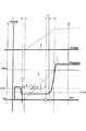
ここで、図6はパワーオンダウン変速の場合の各部の変化を示すグラフ図である。なお、図6において、符号Aは解放側摩擦係合要素の油圧サーボに供給される油圧の変化を示すグラフ、符号Bはアクセル開度(スロットル開度)の変化を示すグラフ、符号Cはエンジントルクの変化を示すグラフ、符号Dはエンジン回転数の変化を示すグラフ、符号Eは入力回転数(入力軸10の回転数)の変化を示すグラフ、符号Fは係合側摩擦係合要素の油圧サーボに供給される油圧の変化を示すグラフである。ここでは、一例として「5−4変速」の場合について説明するため、グラフAは解放側摩擦係合要素であるクラッチC−3の変化を示し、グラフFは係合側摩擦係合要素であるクラッチC−1の変化を示す。図6において、横軸は時間を示し、縦軸は油圧、回転数、トルク及びアクセル開度を重複して示す。 Here, FIG. 6 is a graph showing the change of each part in the case of the power-on down shift. In FIG. 6, reference numeral A is a graph showing a change in hydraulic pressure supplied to the hydraulic servo of the disengagement side friction engagement element, reference numeral B is a graph showing a change in accelerator opening (throttle opening), and reference C is an engine. A graph showing a change in torque, a symbol D showing a graph showing a change in engine speed, a symbol E showing a graph showing a change in input rotational speed (the rotational speed of the input shaft 10), and a code F showing an engagement side frictional engagement element. It is a graph which shows the change of the oil pressure supplied to a hydraulic servo. Here, in order to explain the case of “5-4 shift” as an example, graph A shows the change of the clutch C-3 that is the disengagement side frictional engagement element, and graph F is the engagement side frictional engagement element. The change of the clutch C-1 is shown. In FIG. 6, the horizontal axis indicates time, and the vertical axis indicates the hydraulic pressure, the rotational speed, the torque, and the accelerator opening in an overlapping manner.
すなわち、パワーオンダウン変速における変化点aでは、アクセルペダルが踏み込まれることでスロットルが開放しているため、エンジン回転数や入力回転数の変化は、油圧指令手段71の制御で解放側摩擦係合要素の係合が解除されることによって発生する。つまり、解放側油圧がグラフAのように正常に下降すれば、エンジン回転数及び入力回転数は変化点aから速やかに上昇する。係合側摩擦係合要素としてのクラッチC−1は、油圧指令手段71の制御で、解放側摩擦係合要素としてのクラッチC−3の解放にタイミングを合わせて供給される油圧で係合開始してガタ詰めされた後、楕円丸部Gに示すように、パワーオフダウン変速時に比して低い待機圧で待機し(つまり、係合圧を、イナーシャ相中も低く推移させ)、変速の終期に一気に油圧を上昇(つまり、変速終了時に急上昇)させて係合し、エンジントルクによって上昇する回転を、変速終了時の初期段階で掴む。このため、前述したように、パワーオンダウン変速の場合には、エンジン2の回転が該エンジン2の駆動力により上昇するように、係合側摩擦係合要素(例えば5−4変速ではC−1)の油圧サーボ(例えば41)に供給する係合圧を、イナーシャ相中も低く推移させ、変速終了時に急上昇させるように制御するのである。なお、変速進行率(shiftR)が100[%]になった時、または、例えば5→4変速の場合に、ギヤ比が4速のギヤ比になった時に油圧が上昇を開始できるように油圧の上昇制御を開始しているため、上記「変速終了時」とは、変速進行率が最大(Max)になった時、または変速後のギヤ比にギヤ比が移行した時点を意味する。
That is, at the change point a in the power-on down shift, since the throttle is released by depressing the accelerator pedal, changes in the engine speed and the input speed are controlled by the hydraulic command means 71 in the disengagement side frictional engagement. Occurs when the element is disengaged. That is, if the release side hydraulic pressure drops normally as shown in graph A, the engine speed and the input speed rise quickly from the change point a. The clutch C-1 as the engagement side frictional engagement element is engaged by the hydraulic pressure supplied in time with the release of the clutch C-3 as the release side frictional engagement element under the control of the hydraulic pressure command means 71. Then, as shown by the oval circle G, the engine waits at a standby pressure lower than that at the time of power-off downshifting (that is, the engagement pressure is kept low during the inertia phase). At the end, the hydraulic pressure is increased at once (that is, rapidly increased at the end of the shift) and engaged, and the rotation that is increased by the engine torque is grasped at the initial stage at the end of the shift. Therefore, as described above, in the case of the power-on down shift, the engagement side frictional engagement element (for example, the C− in the 5-4 shift) is set so that the rotation of the
一方、図7はパワーオフダウン変速の場合の各部の変化を示すグラフ図である。なお、図7において、符号A,C,D,E,Fは図6と同様のグラフを意味している。同図においても「5−4変速」について説明するため、グラフAは解放側のクラッチC−3の変化を、グラフFは係合側のクラッチC−1の変化を示す。 On the other hand, FIG. 7 is a graph showing the change of each part in the case of the power-off downshift. In FIG. 7, symbols A, C, D, E, and F mean the same graphs as in FIG. In the same figure, in order to explain “5-4 shift”, graph A shows the change of the release-side clutch C-3, and graph F shows the change of the engagement-side clutch C-1.
すなわち、パワーオフダウン変速における変化点bでは、エンジン回転数や入力回転数の変化は、油圧指令手段71の制御で、係合側のクラッチC−1の油圧サーボ41への供給油圧を早めに上昇させてガタ詰めし、楕円丸部Hに示すように、パワーオンダウン変速時に比して高い待機圧で待機することによって発生する。このパワーオフダウン変速では、アクセルペダルが踏まれないためエンジントルクが低く、係合するクラッチC−1によって回転変化を起こすために、楕円丸部Hの油圧(待機圧、係合圧)が高くされている。このため、前述したように、パワーオフダウン変速の場合には、係合側摩擦係合要素(例えば5→4変速ではC−1)の係合力によりエンジン2の回転(トルク)を引き摺って上昇させ得るように、上記係合側摩擦係合要素の油圧サーボ(例えば41)に供給する係合圧を、パワーオンダウン変速の場合に比して高くなるように制御する。
That is, at the change point b in the power-off down shift, the change in the engine speed or the input speed is controlled by the hydraulic pressure command means 71 so that the hydraulic pressure supplied to the
ここで、図11は、ダウンシフト変速におけるトルク検出条件等の不具合波形を示すグラフ図である。同図において、符号Aは解放側油圧の変化を示すグラフ、符号Bはスロットル開度の変化を示すグラフ、符号Cはエンジントルクの変化を示すグラフ、符号Dはエンジン回転数の変化を示すグラフ、符号Eは入力回転数の変化を示すグラフ、符号Fは係合側の供給油圧の変化を示すグラフである。 Here, FIG. 11 is a graph showing a failure waveform such as a torque detection condition in the downshift. In the same figure, symbol A is a graph showing changes in the release side hydraulic pressure, symbol B is a graph showing changes in throttle opening, symbol C is a graph showing changes in engine torque, and symbol D is a graph showing changes in engine speed. , E is a graph showing changes in the input rotational speed, and F is a graph showing changes in the supply hydraulic pressure on the engagement side.
図11において、丸Iに示す時点では、回転変化が起こっていないため(グラフE参照)、解放不良と判定されるべきであるが、係合側油圧がしきい値に達していないため、解放不良判定とはならず、また、丸Jに示す時点では、係合側油圧がしきい値に達したが、回転変化が起こって(グラフE参照)変速開始判断がなされたため、この場合も解放不良判定とはならない。つまり、図11に示すような場合、パワーオンダウン変速時に、回転変化が起きない時間としては十分であるが油圧条件を満たしていないため解放不良判定とはならず、その後油圧条件を満たしたとしても係合油圧が上昇して回転変化が起きて変速開始判断がなされてしまうため、解放不良判定はできないことになる。 In FIG. 11, since no change in rotation has occurred at the time indicated by circle I (see graph E), it should be determined that the release is defective. However, the engagement side hydraulic pressure has not reached the threshold value, so the release is released. At the time indicated by circle J, the engagement-side hydraulic pressure has reached the threshold value, but the change in rotation has occurred (see graph E) and the shift start determination has been made. It is not a defect judgment. In other words, in the case shown in FIG. 11, it is assumed that the time during which the rotational change does not occur during the power-on down shift is sufficient, but the release condition is not determined because the hydraulic condition is not satisfied, and the hydraulic condition is satisfied thereafter. However, since the engagement hydraulic pressure rises and a rotation change occurs and the shift start determination is made, the release failure determination cannot be made.
ここで、図8(a)は、上述したパワーオンダウン変速及びパワーオフダウン変速を含むダウンシフト変速におけるしきい値の設定に関して説明するためのグラフで、例えば5−4変速時の検出条件を示し、解放側摩擦係合要素としてクラッチC−3が示され、係合側摩擦係合要素としてクラッチC−1が示されている。図8(a)において、符号Aaは解放側油圧の正常時の変化を示すグラフ、符号Abは解放側油圧の異常時の変化を示すグラフである。符号Eは入力回転数の変化を示すグラフであり、符号Eaは入力回転数の正常時の変化を示すグラフ、符号Ebは入力回転数の異常時の変化を示すグラフである。符号Fは係合側の供給油圧の変化を示すグラフである。また、図8(b)は5−4変速に係る速度線図である。 Here, FIG. 8A is a graph for explaining the threshold setting in the downshift including the power-on-down shift and the power-off-down shift described above. For example, the detection condition at the time of the 5-4 shift is shown. The clutch C-3 is shown as the release-side frictional engagement element, and the clutch C-1 is shown as the engagement-side frictional engagement element. In FIG. 8A, the symbol Aa is a graph showing the change when the release side hydraulic pressure is normal, and the symbol Ab is a graph showing the change when the release side hydraulic pressure is abnormal. Reference symbol E is a graph showing changes in the input rotational speed, reference symbol Ea is a graph showing changes in the normal input rotational frequency, and reference symbol Eb is a graph showing changes in the abnormal input rotational speed. Reference symbol F is a graph showing a change in the supply hydraulic pressure on the engagement side. FIG. 8B is a speed diagram for 5-4 shift.
すなわち、図3の本自動変速機構の係合表を参照しつつ説明すると、5−4変速を示す図8(b)において、5速段で係合しているクラッチC−3が円滑に解放されずにグラフAbに示すように異常状態になると、4速段への移行で係合されるべきクラッチC−1が円滑に係合し難くなる。従って、5速段で係合しているクラッチC−3を正常に解放させ(グラフAa)、クラッチC−1を正常に係合させて(グラフF)、入力回転数をグラフEaのように正常に上昇させて4速段に移行させるために必要なクラッチC−3のトルク容量Toは、油圧指令手段71にて以下のように設定・制御される。つまり、
解放側摩擦係合要素のトルク容量To<(エンジントルク×エンジントルクのトルク分担+係合側摩擦係合要素のトルク容量×係合側摩擦係合要素のトルク分担)
として設定・制御される。
That is, with reference to the engagement table of the automatic transmission mechanism in FIG. 3, the clutch C-3 engaged at the fifth gear is smoothly released in FIG. If it becomes an abnormal state as shown in the graph Ab without being engaged, the clutch C-1 to be engaged at the shift to the fourth speed stage becomes difficult to engage smoothly. Accordingly, the clutch C-3 engaged at the fifth speed is normally released (graph Aa), the clutch C-1 is normally engaged (graph F), and the input rotational speed is as shown in the graph Ea. The torque capacity To of the clutch C-3 that is necessary for normally raising and shifting to the fourth speed is set and controlled by the hydraulic pressure command means 71 as follows. That means
Torque capacity To of the disengagement side frictional engagement element To <(engine torque × torque sharing of engine torque + torque capacity of engagement side frictional engagement element × torque sharing of engagement side frictional engagement element)
Set and controlled as
即ち、解放不良判定において油圧指令手段71は、入力トルク検出手段73により計測されたエンジントルクに、トルク分担判定手段74により判定された、変速段に応じて係合中のクラッチやブレーキにおけるトルク分担を掛け(乗算し)、その値に係合側のトルク容量×トルク分担を合算して求め、この値よりも小さい値となるように、解放側のトルク容量Toを算出することで、解放側トルク容量が係合側トルク容量を上回るように設定する。なお、上記トルク分担は、前述したように、変速段の各ギヤ比に基づきクラッチやブレーキにて必要とされる入力トルクに対する比率である。 That is, in the release failure determination, the hydraulic pressure command means 71 uses the engine torque measured by the input torque detection means 73 and the torque sharing in the engaged clutch or brake determined by the torque sharing determination means 74 according to the gear position. Is multiplied by (multiplied), and the value obtained by adding the torque capacity on the engagement side multiplied by the torque share, and calculating the torque capacity To on the disengagement side so as to be smaller than this value. The torque capacity is set to exceed the engagement side torque capacity. Note that, as described above, the torque sharing is a ratio to the input torque required for the clutch and the brake based on the gear ratios of the shift speeds.
ここで、図9(a)〜(c)は本実施形態の実施型においての変化を示し、(a)はエンジントルクの変化を示すグラフ、(b)は係合側のクラッチC−1の油圧サーボ41への供給油圧Pc1(C1圧)の変化を示すグラフ、(c)は(a)と(b)に示す変化を合成した状態で示すグラフである。図9(d),(e),(f)は、図9(a),(b),(c)にそれぞれ対応する、理論的に変速進行率が生じるはずの値(理論値)を示すグラフである。
Here, FIGS. 9A to 9C show changes in the embodiment type of the present embodiment, FIG. 9A is a graph showing changes in engine torque, and FIG. 9B is a graph of the clutch C-1 on the engagement side. The graph which shows the change of supply hydraulic pressure Pc1 (C1 pressure) to the
図9(a)はエンジントルクの実施型を示すものであるが、エンジントルクは、フェール判定手段79が解放不良判定に際して所定値として設定される例えばL[Nm]で左右に分けられ、同図の左から右に向かってリニアに上昇する。横軸の左側はパワーオフダウン変速の領域を示し、右側はパワーオンダウン変速の領域を示す。これを理論値で表すと、図9(d)に示すように、例えばQ[Nm]の部分で、パワーオフダウン変速とパワーオンダウン変速とに分けられる。 FIG. 9A shows an engine torque implementation type. The engine torque is divided into left and right by, for example, L [Nm], which is set as a predetermined value when the failure determination means 79 determines the release failure. Ascends linearly from left to right. The left side of the horizontal axis indicates a power off / down shift area, and the right side indicates a power on / down shift area. When this is expressed by a theoretical value, as shown in FIG. 9 (d), for example, at Q [Nm], it can be divided into a power-off down shift and a power-on down shift.
図9(b)は、解放側の例えばクラッチC−1の油圧サーボ41の油圧(C1圧)の実施型を示すものであるが、グラフの左側はパワーオフダウン変速時に設定される第1の値(例えばM[kPa])を示し、グラフの右側はパワーオンダウン変速時に設定される第2の値(例えばN[kPa])を示している。これを理論値で表すと、図9(e)に示すように、例えばR[kPa]の部分で、パワーオフダウン変速とパワーオンダウン変速とに分けられる。この場合、グラフは左から右に向かってリニアに減少する。
FIG. 9B shows an implementation type of the hydraulic pressure (C1 pressure) of the
図9(c)は、図9(a)のエンジントルクと図9(b)のC1圧とを合成したものであるが、グラフ左側のパワーオフダウン変速領域とグラフ右側のパワーオンダウン変速領域とで、それぞれ、変速進行率例えばP[%]の細破線から、上方の変速進行率例えば100[%]の太破線に向かってリニアに上昇している。これを理論値で表すと、図9(f)に示すように、上方の変速進行率100[%]の太破線の下方にて平行なグラフの中央部が変速進行率P[%]となる。 FIG. 9 (c) is a combination of the engine torque of FIG. 9 (a) and the C1 pressure of FIG. 9 (b). The power off down shift region on the left side of the graph and the power on down shift region on the right side of the graph. And linearly rising from a thin broken line with a shift progress rate, for example, P [%], toward a thick broken line with an upper shift progress rate, for example, 100 [%]. When this is expressed by a theoretical value, as shown in FIG. 9F, the central portion of the parallel graph below the thick broken line of the upper shift progress rate 100 [%] is the shift progress rate P [%]. .
ついで、図10及び図12を参照して、本自動変速機の制御装置1の解放不良判定時の作用を説明する。図10は、パワーオンダウンシフト変速時の変速進行率等を示すグラフ図である。横軸は時間を示し、縦軸は、変速進行率、回転数及び油圧を重ねて示している。同図において、符号Eは入力回転数の変化を示すグラフ、符号Fは係合側油圧(供給油圧)の変化を示すグラフ、符号Kは変速進行率を示すグラフである。図12は、本制御装置1の作用を説明するフローチャートである。
Next, with reference to FIG. 10 and FIG. 12, the operation of the automatic
すなわち、例えば運転者によりイグニッションがONされると、本制御装置1の油圧制御が開始される。まず、シフトレバー(不図示)の選択位置が、例えばPレンジ又はNレンジである際は、制御部70の油圧指令手段71の電気指令によってノーマルオープンタイプであるリニアソレノイドバルブSLC2、リニアソレノイドバルブSLC3等に通電され、それぞれの入力ポートと出力ポートとを遮断する。ついで、例えばエンジン2が始動されると、エンジン回転に基づくオイルポンプ(不図示)の回転により油圧が発生し、該油圧は、不図示のプライマリレギュレータバルブやソレノイドモジュレータバルブによって、ライン圧PLやモジュレータ圧にそれぞれ調圧出力され、不図示のマニュアルシフトバルブの入力ポートと油路dを介してリニアソレノイドバルブSLC3の入力ポートSLC3aとにライン圧PLが入力される。
That is, for example, when the ignition is turned on by the driver, the hydraulic control of the
そして、例えば運転手がシフトレバーをNレンジ位置からDレンジ位置にすることにより、油圧の切換えで変速が行われて走行した後、例えば5速段での走行中に、4速段に掴み換えでダウンシフト変速する場合、以下のようになる。 Then, for example, when the driver moves the shift lever from the N range position to the D range position and shifts by changing the hydraulic pressure, the driver shifts to the fourth speed stage while driving at the fifth speed stage, for example. When downshifting with, the following occurs.
すなわち、ダウンシフト変速時において、所定のタイミングで変速が開始されると(時点t1)、或るタイミング(時点t2)からタイマーがスタートされる(ステップS1)。そして、所定時間(タイマーで計測されるT)が経過する中で、或る一定以上の油圧が出ているにも拘わらず、グラフEのように、所定量の回転変化が発生していない場合、次のようにして解放不良を判定する。 That is, when a downshift is started and a shift is started at a predetermined timing (time t 1 ), a timer is started from a certain timing (time t 2 ) (step S1). When a predetermined amount of rotational change does not occur as shown in graph E, even though the hydraulic pressure exceeds a certain level while the predetermined time (T measured by the timer) elapses. The release failure is determined as follows.
つまり、タイマースタート後、所定時間Tが経過した時点(S2)(図10のt4)で、ダウンシフト判別手段76が、エンジントルクは所定値(例えばL[N・m])を超えているか否かを判断する。その結果、エンジントルクが所定値を超えていなければパワーオフダウン変速と判別してステップS5に進み、エンジントルクが所定値を超えていればパワーオンダウンと判別してステップS4に進む。 That is, at the time when the predetermined time T has elapsed after the timer is started (S2) (t 4 in FIG. 10), the downshift determining means 76 determines whether the engine torque exceeds a predetermined value (for example, L [N · m]). Judge whether or not. As a result, if the engine torque does not exceed the predetermined value, it is determined as a power-off down shift and the process proceeds to step S5. If the engine torque exceeds the predetermined value, it is determined as a power-on down and the process proceeds to step S4.
フェール判定手段79は、パワーオフダウン変速と判別されて進んだステップS5において、4速段への変速における解放側摩擦係合要素としてのクラッチC−1への供給油圧(係合圧)が第1の値(例えばM[kPa])を超えているか否かを判断し、超えた時点(図10のt5)でステップS6に進み、超えなければステップS3を繰り返す。 The fail determination means 79 determines that the supply hydraulic pressure (engagement pressure) to the clutch C-1 as the disengagement side frictional engagement element in the shift to the fourth speed is the first in step S5 which has been determined as the power-off downshift. It is determined whether or not a value of 1 (for example, M [kPa]) is exceeded, and when it exceeds (t 5 in FIG. 10), the process proceeds to step S6, and if not, step S3 is repeated.
一方、フェール判定手段79は、パワーオンダウン変速と判別されて進んだステップS4において、解放側摩擦係合要素としてのクラッチC−1への供給油圧(係合圧)が第2の値(例えばN[kPa])を超えているか否かを判断し、超えた時点(図10のt5)でステップS6に進み、超えなければステップS3を繰り返す。 On the other hand, the fail determination means 79 determines that the power supply pressure (engagement pressure) to the clutch C-1 as the disengagement side frictional engagement element is a second value (for example, in step S4 which has been determined as a power-on downshift). N [kPa]) is determined, and if it exceeds (t 5 in FIG. 10), the process proceeds to step S6, and if not, step S3 is repeated.
そして、フェール判定手段79は、ステップS6において、shiftR(変速進行率(度))が例えばP[%]未満であるか否かを判断する。その結果、変速進行率がP[%]未満である場合は、フェールを検出(解放不良と判定)したとして(S7)、フェールセーフ実行手段80が、ステップS8にてフェールアクションを実施する。つまり、フェールセーフ実行手段80が油圧指令手段71にその旨の指示を行い、当該ダウンシフト変速を中断して変速開始前の5速段に戻すフェールアクションを実行する。一方、ステップS6において、変速進行率がP[%]以上である場合はステップS9に進み、油圧指令手段71に指示を行うことなく、正常と見なした通常変速制御を実行する。
In step S6, the
図10において例えばしきい値がS[kPa]に設定されている場合、解放側摩擦係合要素としてのクラッチC−3が適正に解放されていなくて所定の回転変化が起きていないとき、図10の時点t4では、油圧が或るしきい値に満たないため解放不良とは判定されないが、それまでの待機圧から油圧を上げて係合を完了する時点(図10のt4’)以降で解放不良を判定されることになる。つまり例えば、パワーオンダウン変速時の第2の値を時点t2〜t4’の区間の油圧(待機圧中)に設定した際、時点t2〜t4’の区間(待機圧中)では油圧上昇が緩やかであることに起因して時点t2側でも時点t4’側でも油圧に大きな差が見られないため、変速進行率が速く変化し始めた場合であっても遅く変化し始めた場合であっても、必ず変速進行率が一定値を超える油圧を設定することは難しいが、第2の値を、油圧が待機圧から上昇し始める時点t4’以降の油圧に設定することで、係合を完了させるために油圧が上昇し始めてから解放不良を判定することができ、従って、判定の精度を向上させて誤判定を無くすことができる。
In FIG. 10, for example, when the threshold value is set to S [kPa], when the clutch C-3 as the disengagement side frictional engagement element is not properly released and a predetermined rotational change does not occur, 10 At time t 4 the is not determined that the release failure because hydraulic pressure is less than the certain threshold, it up to the point of completing the engagement by raising the hydraulic pressure from the standby pressure (t 4 in Fig. 10 ') Thereafter, a release failure is determined. Thus, for example, 'when set in the section of the hydraulic (standby during pressurization), the time t 2 ~t 4' a second value of the power-on downshift time t 2 ~
また、以上説明した本実施の形態の自動変速機3は、前進6速段を達成し得るものを一例として説明したが、本発明を適用し得る自動変速機は、これに限られるものではなく、他の種別の自動変速機であっても良いことは勿論である。
Moreover, although the
1 自動変速機の制御装置
2 駆動源(エンジン)
10 入力軸
11 出力軸(カウンタギヤ)
41〜45 油圧サーボ
76 ダウンシフト判別手段
77 係合圧監視手段
79 フェール判定手段
80 フェールセーフ実行手段
B−1,B−2 摩擦係合要素(ブレーキ)
C−1 摩擦係合要素、係合側摩擦係合要素(クラッチ)
C−2 摩擦係合要素(クラッチ)
C−3 摩擦係合要素、解放側摩擦係合要素(クラッチ)
1 Automatic
10
41-45 Hydraulic servo 76 Downshift discriminating means 77 Engaging pressure monitoring means 79 Fail judging means 80 Fail safe execution means B-1, B-2 Friction engaging element (brake)
C-1 Friction engagement element, engagement side friction engagement element (clutch)
C-2 Friction engagement element (clutch)
C-3 Friction engagement element, release side friction engagement element (clutch)
Claims (5)
ダウンシフト変速が開始された際、該ダウンシフト変速はパワーオンダウン変速及びパワーオフダウン変速の何れであるかを判別するダウンシフト判別手段と、
係合側摩擦係合要素の油圧サーボに供給される係合圧を監視する係合圧監視手段と、
前記係合圧がしきい値に達した際に、解放側摩擦係合要素の解放不良を判定するフェール判定手段と、を備え、
前記フェール判定手段は、前記ダウンシフト判別手段によって判別されたダウンシフト変速の種類に応じて前記しきい値を変更してなる、
ことを特徴とする自動変速機の制御装置。 A plurality of friction engagement elements engaged based on engagement pressures respectively supplied to the respective hydraulic servos, an input shaft connected to a drive source, and an output shaft connected to a drive wheel, An automatic transmission that changes a transmission path between the input shaft and the output shaft based on an engagement state of a plurality of friction engagement elements to form a plurality of shift speeds and performs a gripping change shift of the friction engagement elements. In the control device of the machine,
Downshift determining means for determining whether the downshift is a power-on-down shift or a power-off-downshift when the downshift is started;
Engagement pressure monitoring means for monitoring the engagement pressure supplied to the hydraulic servo of the engagement side frictional engagement element;
Fail determination means for determining a release failure of the release-side frictional engagement element when the engagement pressure reaches a threshold value,
The fail determination means changes the threshold according to the type of downshift gear determined by the downshift determination means.
A control device for an automatic transmission.
請求項1記載の自動変速機の制御装置。 The fail determination means sets the threshold value to be lower at the time of power-on down shift than at the time of power off-down shift.
The control device for an automatic transmission according to claim 1.
請求項1又は2記載の自動変速機の制御装置。 The downshift discriminating means compares the torque of the driving source with a predetermined value, determines that it is a power-off downshift when it is determined that the torque is smaller than the predetermined value, and determines that it is greater than the predetermined value. It is discriminated as a shift,
The control device for an automatic transmission according to claim 1 or 2.
請求項1乃至3の何れか1項記載の自動変速機の制御装置。 When the failure determination means determines that the release failure is present, the apparatus further includes fail-safe execution means that executes a fail action that interrupts the downshift and shifts to a shift stage before the start of the shift to make the fail safe. ,
The control device for an automatic transmission according to any one of claims 1 to 3.
請求項1乃至4の何れか1項記載の自動変速機の制御装置。 When the downshift determined by the downshift determiner is a power-on downshift, the hydraulic servo of the engagement side frictional engagement element is set so that the rotation of the drive source is increased by the driving force of the drive source. The hydraulic pressure command means for causing the engagement pressure to be supplied to be low during the inertia phase and to rapidly increase at the end of shifting,
The control device for an automatic transmission according to any one of claims 1 to 4.
Priority Applications (1)
| Application Number | Priority Date | Filing Date | Title |
|---|---|---|---|
| JP2008255853A JP5098934B2 (en) | 2008-09-30 | 2008-09-30 | Control device for automatic transmission |
Applications Claiming Priority (1)
| Application Number | Priority Date | Filing Date | Title |
|---|---|---|---|
| JP2008255853A JP5098934B2 (en) | 2008-09-30 | 2008-09-30 | Control device for automatic transmission |
Publications (2)
| Publication Number | Publication Date |
|---|---|
| JP2010084874A true JP2010084874A (en) | 2010-04-15 |
| JP5098934B2 JP5098934B2 (en) | 2012-12-12 |
Family
ID=42249025
Family Applications (1)
| Application Number | Title | Priority Date | Filing Date |
|---|---|---|---|
| JP2008255853A Expired - Fee Related JP5098934B2 (en) | 2008-09-30 | 2008-09-30 | Control device for automatic transmission |
Country Status (1)
| Country | Link |
|---|---|
| JP (1) | JP5098934B2 (en) |
Cited By (1)
| Publication number | Priority date | Publication date | Assignee | Title |
|---|---|---|---|---|
| CN114198442A (en) * | 2021-11-30 | 2022-03-18 | 中国重汽集团济南动力有限公司 | Method for monitoring sliding state of clutch |
Citations (5)
| Publication number | Priority date | Publication date | Assignee | Title |
|---|---|---|---|---|
| JP2000009224A (en) * | 1998-06-23 | 2000-01-11 | Unisia Jecs Corp | Fail-safe device for vehicular automatic transmission |
| JP2004125075A (en) * | 2002-10-03 | 2004-04-22 | Daihatsu Motor Co Ltd | Speed change control method of automatic transmission |
| JP2005009590A (en) * | 2003-06-19 | 2005-01-13 | Toyota Motor Corp | Abnormality detecting device for transmission |
| JP2005291309A (en) * | 2004-03-31 | 2005-10-20 | Denso Corp | Automatic transmission controller |
| JP2007255518A (en) * | 2006-03-22 | 2007-10-04 | Jatco Ltd | Shift controller of automatic transmission |
-
2008
- 2008-09-30 JP JP2008255853A patent/JP5098934B2/en not_active Expired - Fee Related
Patent Citations (5)
| Publication number | Priority date | Publication date | Assignee | Title |
|---|---|---|---|---|
| JP2000009224A (en) * | 1998-06-23 | 2000-01-11 | Unisia Jecs Corp | Fail-safe device for vehicular automatic transmission |
| JP2004125075A (en) * | 2002-10-03 | 2004-04-22 | Daihatsu Motor Co Ltd | Speed change control method of automatic transmission |
| JP2005009590A (en) * | 2003-06-19 | 2005-01-13 | Toyota Motor Corp | Abnormality detecting device for transmission |
| JP2005291309A (en) * | 2004-03-31 | 2005-10-20 | Denso Corp | Automatic transmission controller |
| JP2007255518A (en) * | 2006-03-22 | 2007-10-04 | Jatco Ltd | Shift controller of automatic transmission |
Cited By (2)
| Publication number | Priority date | Publication date | Assignee | Title |
|---|---|---|---|---|
| CN114198442A (en) * | 2021-11-30 | 2022-03-18 | 中国重汽集团济南动力有限公司 | Method for monitoring sliding state of clutch |
| CN114198442B (en) * | 2021-11-30 | 2023-09-22 | 中国重汽集团济南动力有限公司 | Clutch sliding state monitoring method |
Also Published As
| Publication number | Publication date |
|---|---|
| JP5098934B2 (en) | 2012-12-12 |
Similar Documents
| Publication | Publication Date | Title |
|---|---|---|
| JP4400639B2 (en) | Hydraulic control device for automatic transmission | |
| JP2008232355A (en) | Automatic transmission | |
| JP2008002553A (en) | Controller for automatic transmission | |
| JP5273109B2 (en) | Control device for automatic transmission | |
| US8214118B2 (en) | Control apparatus for automatic transmission | |
| JP4162024B2 (en) | Control device for automatic transmission for vehicle | |
| JP2007146902A (en) | Speed-change controller for automatic transmission | |
| JP5440536B2 (en) | Automatic transmission and transmission gear abnormality determination method | |
| JP5136534B2 (en) | Control device for automatic transmission | |
| JP2009156396A (en) | Abnormality determination device of linear solenoid valve for vehicle | |
| US6508736B2 (en) | Shift control apparatus for automatic transmission | |
| JP3991264B2 (en) | Control device for automatic transmission | |
| JP5098934B2 (en) | Control device for automatic transmission | |
| JP5338504B2 (en) | Control device for automatic transmission | |
| JP7185790B2 (en) | AUTOMATIC TRANSMISSION CONTROL DEVICE AND CONTROL METHOD | |
| JP5056706B2 (en) | Control device for automatic transmission | |
| JP5115473B2 (en) | Control device for automatic transmission | |
| JP5272649B2 (en) | Control device for automatic transmission | |
| JP4978605B2 (en) | Control device for automatic transmission | |
| JP2007205431A (en) | Automatic transmission control device | |
| JP5098935B2 (en) | Control device for automatic transmission | |
| JP2008151190A (en) | Controller of automatic transmission for vehicle | |
| JP4499053B2 (en) | Control device for automatic transmission | |
| JP2007100733A (en) | Control device for automatic transmission | |
| JP5126056B2 (en) | Control device for automatic transmission |
Legal Events
| Date | Code | Title | Description |
|---|---|---|---|
| A621 | Written request for application examination |
Free format text: JAPANESE INTERMEDIATE CODE: A621 Effective date: 20110125 |
|
| A977 | Report on retrieval |
Free format text: JAPANESE INTERMEDIATE CODE: A971007 Effective date: 20120313 |
|
| A131 | Notification of reasons for refusal |
Free format text: JAPANESE INTERMEDIATE CODE: A131 Effective date: 20120321 |
|
| A521 | Written amendment |
Free format text: JAPANESE INTERMEDIATE CODE: A523 Effective date: 20120510 |
|
| TRDD | Decision of grant or rejection written | ||
| A01 | Written decision to grant a patent or to grant a registration (utility model) |
Free format text: JAPANESE INTERMEDIATE CODE: A01 Effective date: 20120828 |
|
| A01 | Written decision to grant a patent or to grant a registration (utility model) |
Free format text: JAPANESE INTERMEDIATE CODE: A01 |
|
| A61 | First payment of annual fees (during grant procedure) |
Free format text: JAPANESE INTERMEDIATE CODE: A61 Effective date: 20120910 |
|
| FPAY | Renewal fee payment (event date is renewal date of database) |
Free format text: PAYMENT UNTIL: 20151005 Year of fee payment: 3 |
|
| R150 | Certificate of patent or registration of utility model |
Ref document number: 5098934 Country of ref document: JP Free format text: JAPANESE INTERMEDIATE CODE: R150 Free format text: JAPANESE INTERMEDIATE CODE: R150 |
|
| LAPS | Cancellation because of no payment of annual fees |