JP2005291309A - Automatic transmission control device - Google Patents
Automatic transmission control device Download PDFInfo
- Publication number
- JP2005291309A JP2005291309A JP2004105561A JP2004105561A JP2005291309A JP 2005291309 A JP2005291309 A JP 2005291309A JP 2004105561 A JP2004105561 A JP 2004105561A JP 2004105561 A JP2004105561 A JP 2004105561A JP 2005291309 A JP2005291309 A JP 2005291309A
- Authority
- JP
- Japan
- Prior art keywords
- hydraulic pressure
- hydraulic
- friction element
- engagement
- automatic transmission
- Prior art date
- Legal status (The legal status is an assumption and is not a legal conclusion. Google has not performed a legal analysis and makes no representation as to the accuracy of the status listed.)
- Granted
Links
Images

Classifications
-
- F—MECHANICAL ENGINEERING; LIGHTING; HEATING; WEAPONS; BLASTING
- F16—ENGINEERING ELEMENTS AND UNITS; GENERAL MEASURES FOR PRODUCING AND MAINTAINING EFFECTIVE FUNCTIONING OF MACHINES OR INSTALLATIONS; THERMAL INSULATION IN GENERAL
- F16H—GEARING
- F16H61/00—Control functions within control units of change-speed- or reversing-gearings for conveying rotary motion ; Control of exclusively fluid gearing, friction gearing, gearings with endless flexible members or other particular types of gearing
- F16H61/12—Detecting malfunction or potential malfunction, e.g. fail safe ; Circumventing or fixing failures
-
- F—MECHANICAL ENGINEERING; LIGHTING; HEATING; WEAPONS; BLASTING
- F16—ENGINEERING ELEMENTS AND UNITS; GENERAL MEASURES FOR PRODUCING AND MAINTAINING EFFECTIVE FUNCTIONING OF MACHINES OR INSTALLATIONS; THERMAL INSULATION IN GENERAL
- F16H—GEARING
- F16H59/00—Control inputs to control units of change-speed- or reversing-gearings for conveying rotary motion
- F16H59/68—Inputs being a function of gearing status
- F16H2059/683—Sensing pressure in control systems or in fluid-controlled devices, e.g. by pressure sensors
-
- F—MECHANICAL ENGINEERING; LIGHTING; HEATING; WEAPONS; BLASTING
- F16—ENGINEERING ELEMENTS AND UNITS; GENERAL MEASURES FOR PRODUCING AND MAINTAINING EFFECTIVE FUNCTIONING OF MACHINES OR INSTALLATIONS; THERMAL INSULATION IN GENERAL
- F16H—GEARING
- F16H61/00—Control functions within control units of change-speed- or reversing-gearings for conveying rotary motion ; Control of exclusively fluid gearing, friction gearing, gearings with endless flexible members or other particular types of gearing
- F16H61/12—Detecting malfunction or potential malfunction, e.g. fail safe ; Circumventing or fixing failures
- F16H2061/1204—Detecting malfunction or potential malfunction, e.g. fail safe ; Circumventing or fixing failures for malfunction caused by simultaneous engagement of different ratios resulting in transmission lock state or tie-up condition
-
- F—MECHANICAL ENGINEERING; LIGHTING; HEATING; WEAPONS; BLASTING
- F16—ENGINEERING ELEMENTS AND UNITS; GENERAL MEASURES FOR PRODUCING AND MAINTAINING EFFECTIVE FUNCTIONING OF MACHINES OR INSTALLATIONS; THERMAL INSULATION IN GENERAL
- F16H—GEARING
- F16H61/00—Control functions within control units of change-speed- or reversing-gearings for conveying rotary motion ; Control of exclusively fluid gearing, friction gearing, gearings with endless flexible members or other particular types of gearing
- F16H61/12—Detecting malfunction or potential malfunction, e.g. fail safe ; Circumventing or fixing failures
- F16H2061/1208—Detecting malfunction or potential malfunction, e.g. fail safe ; Circumventing or fixing failures with diagnostic check cycles; Monitoring of failures
-
- F—MECHANICAL ENGINEERING; LIGHTING; HEATING; WEAPONS; BLASTING
- F16—ENGINEERING ELEMENTS AND UNITS; GENERAL MEASURES FOR PRODUCING AND MAINTAINING EFFECTIVE FUNCTIONING OF MACHINES OR INSTALLATIONS; THERMAL INSULATION IN GENERAL
- F16H—GEARING
- F16H59/00—Control inputs to control units of change-speed- or reversing-gearings for conveying rotary motion
- F16H59/68—Inputs being a function of gearing status
-
- Y—GENERAL TAGGING OF NEW TECHNOLOGICAL DEVELOPMENTS; GENERAL TAGGING OF CROSS-SECTIONAL TECHNOLOGIES SPANNING OVER SEVERAL SECTIONS OF THE IPC; TECHNICAL SUBJECTS COVERED BY FORMER USPC CROSS-REFERENCE ART COLLECTIONS [XRACs] AND DIGESTS
- Y10—TECHNICAL SUBJECTS COVERED BY FORMER USPC
- Y10S—TECHNICAL SUBJECTS COVERED BY FORMER USPC CROSS-REFERENCE ART COLLECTIONS [XRACs] AND DIGESTS
- Y10S477/00—Interrelated power delivery controls, including engine control
- Y10S477/906—Means detecting or ameliorating the effects of malfunction or potential malfunction
Landscapes
- Engineering & Computer Science (AREA)
- General Engineering & Computer Science (AREA)
- Mechanical Engineering (AREA)
- Control Of Transmission Device (AREA)
Abstract
【課題】 摩擦要素に加わる係合側および解放側の両方の液圧不良を検出する自動変速機制御装置を提供する。
【解決手段】 各摩擦要素に加わる油圧は、2個の油圧スイッチ41、42で検出されている。Dレンジにおいて2速から3速に変速する場合、L/C3は係合状態を継続し、H/C5は解放状態から係合状態に移行し、2−4/B4係合状態から解放状態に移行する。この変速制御において、H/C5に加わる油圧が所定よりも早いタイミングで上昇すると、H/C5に加わる油圧を低圧側で検出する油圧スイッチ41がオンになる。このとき2−4/B4に加わる油圧を高圧側で検出する油圧スイッチ42もオンであると、二重係合が生じたと判定する。
【選択図】 図1PROBLEM TO BE SOLVED: To provide an automatic transmission control device for detecting a hydraulic pressure failure on both an engagement side and a release side applied to a friction element.
The hydraulic pressure applied to each friction element is detected by two hydraulic switches (41, 42). When shifting from the 2nd speed to the 3rd speed in the D range, L / C3 continues the engaged state, H / C5 shifts from the released state to the engaged state, and changes from the 2-4 / B4 engaged state to the released state. Transition. In this shift control, when the hydraulic pressure applied to H / C5 rises at a timing earlier than a predetermined timing, the hydraulic switch 41 that detects the hydraulic pressure applied to H / C5 on the low pressure side is turned on. At this time, if the hydraulic switch 42 that detects the hydraulic pressure applied to 2-4 / B4 on the high pressure side is also on, it is determined that double engagement has occurred.
[Selection] Figure 1
Description
本発明は、自動変速機の変速機構を液圧制御する自動変速機制御装置に関する。 The present invention relates to an automatic transmission control device that hydraulically controls a transmission mechanism of an automatic transmission.
従来、車両用等に多く利用されている自動変速機は、各摩擦要素に加わる油圧を油圧制御装置で制御し、各摩擦要素が係合または解放されることにより変速を切り換えている(例えば、特許文献1、2参照)。
また、特許文献1、2では、摩擦要素に加わる油圧を1個の油圧スイッチで検出し、油圧スイッチの検出状態の組み合わせから故障の判定を行っている。特許文献1、2のように、摩擦要素に加わる油圧を1個の油圧スイッチで検出している油圧制御装置を図7に示す。
2. Description of the Related Art Conventionally, automatic transmissions that are widely used for vehicles and the like control the hydraulic pressure applied to each friction element with a hydraulic control device, and switch the shift by engaging or releasing each friction element (for example, (See
In
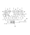
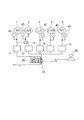
リバースクラッチ(R/C)1、ローリバースブレーキ(LR/B)2、ロークラッチ(L/C)3、2−4ブレーキ(2−4/B)4、ハイクラッチ(H/C)5は油圧により係合または解放される摩擦要素である。符号11〜15は、各摩擦要素に加わる油圧を切り換える制御手段である。制御手段11〜15は、例えば、電磁弁と、電磁弁の指示圧により油路を切り換えるスプール弁とで構成される。マニュアル弁20は、運転者が操作するセレクトレバー30とワイヤ等で連結している。セレクトレバー30により走行レンジが切り換わると、マニュアル弁20は、走行レンジに応じて制御手段11〜15に供給する油圧をライン圧またはドレイン22の油圧に切り換える。油圧スイッチ40は、各摩擦要素に加わる油圧の検出信号を、設定した検出主圧を閾値としてオン、オフ信号で出力する。
Reverse clutch (R / C) 1, low reverse brake (LR /
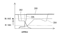
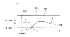
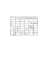
例えば、Dレンジにおいて、図8に示す係合表にしたがって2速から3速に変速を切り換えるとき、図9に示すように、H/C5に加わる油圧205が正常な油圧204よりも早いタイミングで上昇すると、H/C5に加わる油圧を検出する油圧スイッチ40がオンになり、二重係合が生じたと判定できる。図9において、200は、L/C3に加わる油圧を示し、202は解放される2−4/B4に加わる油圧を示している。
For example, in the D range, when the shift is switched from the 2nd speed to the 3rd speed according to the engagement table shown in FIG. 8, the
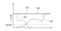
しかしながら、特許文献1、2では、摩擦要素に油圧スイッチを1個だけ設置しているので、各油圧スイッチが検出できる油圧は一種類である。したがって、油圧スイッチ40の検出する検出油圧の設定が図9および図10にように低く、図10に示すように、2−4/B4が解放されず2−4/B4に加わる油圧203が高いままであるときは、故障を判定できないか、二重係合が生じてから二重係合を検出する。逆に検出油圧を高圧に設定すると、図9に示すように、H/C5に加わる油圧205が所定よりも早いタイミングで上昇したときに、二重係合が生じてから二重係合を検出できない。
However, in
二重係合に限らず、油圧スイッチで検出する検出油圧が各摩擦要素で低圧側または高圧側の一種類であると、係合側または解放側の一方だけの油圧不良しか検出できない。
本発明は上記問題を解決するためになされたものであり、摩擦要素に加わる係合側および解放側の両方の液圧不良を検出する自動変速機制御装置を提供することを目的とする。
If the detected hydraulic pressure detected by the hydraulic switch is not limited to double engagement, and only one type of low pressure side or high pressure side is detected in each friction element, only one hydraulic failure on the engagement side or the release side can be detected.
The present invention has been made to solve the above-described problems, and an object of the present invention is to provide an automatic transmission control device that detects hydraulic pressure defects on both the engagement side and the release side applied to the friction element.
請求項1記載の発明によると、液圧検出手段は、少なくとも摩擦要素に加わる第1液圧と、第1液圧よりも高圧の第2液圧とを検出する。したがって、摩擦要素に加わる係合側および解放側の両方の液圧不良を検出できる。
例えば、高負荷時において、係合液圧の不足により摩擦要素に滑りが生じているとか、請求項2記載の発明のように、解放側また係合側の液圧不良により生じる二重係合の発生を検出することにより、各種故障判定が可能である。
According to the first aspect of the invention, the hydraulic pressure detecting means detects at least the first hydraulic pressure applied to the friction element and the second hydraulic pressure higher than the first hydraulic pressure. Accordingly, it is possible to detect a hydraulic pressure failure on both the engagement side and the release side applied to the friction element.
For example, when the load is high, the friction element slips due to insufficient engagement hydraulic pressure, or double engagement caused by hydraulic pressure failure on the disengagement side or engagement side as in the invention of
請求項3記載の発明によると、第1液圧は、摩擦要素を解放方向に付勢するリターンスプリング力に相当する液圧またはその近傍液圧であり、第1液圧より高圧の第2液圧は、最大負荷時において摩擦要素の係合に必要な最低液圧またはその近傍液圧である。したがって、摩擦要素が二重係合を起こす前に故障を検出できる。
According to the invention of
請求項4記載の発明によると、第2液圧は、最大負荷時において摩擦要素の係合に必要な最低液圧よりも高い液圧であり、全種類の変速において第2液圧よりも低い圧力で変速制御されるため、指令値に対して液圧が低下しない故障を確実に検出でき、摩擦要素が二重係合を起こす前に故障を検出できる。
According to the invention described in
請求項5記載の発明によると、液圧検出手段は、第1液圧を閾値としてオン、オフ信号を出力する第1液圧スイッチ、ならびに第2液圧を閾値としてオン、オフ信号を出力する第2液圧スイッチを有する。両スイッチが液圧により作動するオン、オフスイッチであるから、液圧検出手段の構成が簡単である。
According to the invention of
請求項6記載の発明によると、変速切り換え中に、解放される側の摩擦要素の係合圧が第2液圧以上であることを第2液圧スイッチが検出するとともに、係合される側の摩擦要素の係合圧が第1液圧以上であることを第1液圧スイッチが検出するときに、故障判定手段は二重係合であると判定するようにしたので、誤判定を回避しつつ、確実に二重係合を検出できる。 According to the sixth aspect of the present invention, the second hydraulic pressure switch detects that the engagement pressure of the released friction element is equal to or higher than the second hydraulic pressure during the shift switching, and the engaged side When the first hydraulic pressure switch detects that the engagement pressure of the friction element is equal to or higher than the first hydraulic pressure, the failure determination means determines that the engagement is double engagement, thus avoiding erroneous determination. However, double engagement can be reliably detected.
請求項7記載の発明によると、第1液圧スイッチおよび第2液圧スイッチは並列に接続された並列回路を構成し、第1液圧スイッチおよび第2液圧スイッチのオン、オフ状態を並列回路の合成抵抗値として検出する。したがって、第1液圧スイッチおよび第2液圧スイッチのオン、オフ状態を簡単な回路構成で検出できる。 According to the seventh aspect of the present invention, the first hydraulic pressure switch and the second hydraulic pressure switch constitute a parallel circuit connected in parallel, and the on / off states of the first hydraulic pressure switch and the second hydraulic pressure switch are arranged in parallel. It is detected as the combined resistance value of the circuit. Therefore, the on / off states of the first hydraulic pressure switch and the second hydraulic pressure switch can be detected with a simple circuit configuration.
以下、本発明の実施の形態を図に基づいて説明する。
本発明の自動変速機制御装置の一実施形態を図1に示す。既に説明した図7に示す従来の自動変速機制御装置と実質的に同一構成部分には同一符号を付し、説明を省略する。本実施形態においても、図8に示す係合表にしたがって変速が制御される。
Hereinafter, embodiments of the present invention will be described with reference to the drawings.
One embodiment of the automatic transmission control device of the present invention is shown in FIG. Components that are substantially the same as those of the conventional automatic transmission control device shown in FIG. 7 described above are denoted by the same reference numerals, and description thereof is omitted. Also in this embodiment, the shift is controlled according to the engagement table shown in FIG.
図1に示すように、本実施形態の自動変速機制御装置では、各摩擦要素に加わる油圧を液圧検出手段である2個の油圧スイッチ41、42で検出している。図4に油圧スイッチ41の構成を示す。油圧スイッチ41、42は、スイッチがオンになる検出油圧の値が異なるだけで、実質的な構成は同一である。
ターミナル100、102は、ダイヤフラム104が受ける油圧が検出油圧よりも低いときは導通せず、ダイヤフラム104が受ける油圧が検出油圧よりも高いときに導通する。したがって、油圧スイッチ41は、各摩擦要素に加わる油圧が検出油圧よりも低いとオフ状態になり、検出油圧よりも高いとオン状態になる。油圧スイッチ41が検出する第1液圧としての第1油圧は、各摩擦要素を解放方向に付勢するリターンスプリング力に相当する油圧またはその近傍油圧に設定されている。一方、油圧スイッチ42が検出する第2液圧としての第2油圧は、最大負荷時において摩擦要素の係合に必要な最低油圧またはその近傍油圧に設定されている。
As shown in FIG. 1, in the automatic transmission control apparatus of this embodiment, the hydraulic pressure applied to each friction element is detected by two
The
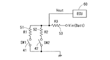
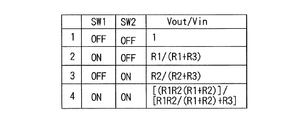
図2に示すように、各摩擦要素に加わる油圧を検出する油圧スイッチ41、42は、抵抗51、52とともに並列回路を形成している。油圧スイッチ41と抵抗51とは直列に接続され、油圧スイッチ42と抵抗52とは直列に接続されている。この並列回路の合成抵抗値は、油圧スイッチ41、42のオン、オフ状態により4通りに変化する。図3に示すように、油圧スイッチ41、42のオン、オフ状態により変化する合成抵抗値に応じて変化する出力電圧Voutと電源電圧Vinとの比Vout/Vinから、故障判定手段であるエンジン制御装置(ECU)60は、油圧スイッチ41、42のオン、オフ状態を検出し、故障判定を行う。
As shown in FIG. 2,
次に、Dレンジにおいて2速から3速に変速する場合の二重係合の検出を例にして故障判定について説明する。
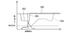
図5に示すように、H/C5に加わる油圧205が所定よりも早いタイミングで上昇すると、H/C5に加わる油圧を低圧側で検出する油圧スイッチ41がオンになる。このとき、2−4/B4に加わる油圧を高圧側で検出する油圧スイッチ42もオンであると、ECU60は二重係合が生じたと判定する。
Next, failure determination will be described by taking double engagement detection when shifting from 2nd speed to 3rd speed in the D range as an example.
As shown in FIG. 5, when the
また、図6に示すように、Dレンジにおいて2速から3速に変速するときに、2−4/B4が解放されず2−4/B4に加わる油圧203が高いままであるときは、タイマ等で所定タイミングを設定することにより、H/C5に加わる油圧204が第1油圧に達し油圧スイッチ41がオンになる前に、2−4/B4に加わる油圧を高圧側で検出する油圧スイッチ42がオンのままであることを検出し、二重係合であると判定する。
Also, as shown in FIG. 6, when shifting from the 2nd speed to the 3rd speed in the D range, if 2-4 / B4 is not released and the
以上説明した上記実施形態では、各摩擦要素に加わる油圧を2個の油圧スイッチで低圧側および高圧側の両方で検出することにより、変速切り換え中に、係合側および解放側の両方の摩擦要素に加わる油圧の不良を検出できる。
また、上記実施形態では、二重係合を起こす以外の摩擦要素、例えばR/C1に加わる油圧も2個の油圧スイッチ41、42で検出している。これにより、高圧側に設定される油圧スイッチ42の検出油圧を、最大負荷で運転するときに必要な最低油圧よりも高くすることにより、高負荷時に係合すべき摩擦要素が油圧不足により滑っていることを検出できる。
In the above-described embodiment, the hydraulic pressure applied to each friction element is detected on both the low pressure side and the high pressure side by two hydraulic switches, so that both the engagement side and the release side friction elements are detected during the shift switching. It is possible to detect a hydraulic pressure applied to the.
In the above embodiment, the hydraulic pressure applied to the friction elements other than the double engagement, for example, R / C1, is also detected by the two
また、油圧スイッチ41、42のオン、オフ状態の組み合わせを、油圧スイッチ41、42および抵抗51、52からなる並列回路の合成抵抗値に応じて変化する出力電圧Voutから検出するので、油圧スイッチ41、42のオン、オフ状態の組み合わせを検出するためにECU60に入力する信号線は1本でよい。したがって、検出信号の本数が減少し、配線が容易になる。
Further, since the combination of the ON and OFF states of the
(他の実施形態)
上記実施形態では、液圧検出手段としての油圧スイッチ41、42により、摩擦要素に加わる油圧を低圧側および高圧側に設定した二種類の検出油圧を基準として検出したが、液圧検出手段としては、摩擦要素に加わる油圧を、油圧の異なる3種類以上に設定した検出油圧を基準として検出してもよい。
(Other embodiments)
In the above embodiment, the hydraulic pressure switches 41 and 42 as the hydraulic pressure detecting means detect the hydraulic pressure applied to the friction element based on two types of detected hydraulic pressures set on the low pressure side and the high pressure side. However, as the hydraulic pressure detecting means, The hydraulic pressure applied to the friction element may be detected with reference to detected hydraulic pressures set to three or more different hydraulic pressures.
上記実施形態では、油圧スイッチ41の検出油圧を、各摩擦要素を解放方向に付勢するリターンスプリング力に相当する油圧またはその近傍油圧に設定し、油圧スイッチ42の検出油圧を、最大負荷時において摩擦要素の係合に必要な最低油圧またはその近傍油圧に設定して二重係合を検出したが、油圧スイッチ41、42の検出油圧を上記値の範囲外に設定して二重係合を検出してもよい。
In the above embodiment, the detected oil pressure of the
また上記実施形態では、タイマ等で所定タイミングを設定することにより、図6においてH/C5に加わる油圧204が第1油圧に達し二重係合が発生する前に、故障と判定しているが、図6において油圧204が第1油圧に達し油圧スイッチ41、42がともにオンになったときに故障と判定してもよい。
上記実施形態では、全ての摩擦要素に加わる油圧を2個の油圧スイッチ41、42で検出する構成を採用しているが、二重係合を起こす摩擦要素にだけそれぞれ2個の油圧スイッチを設けてもよい。
Further, in the above embodiment, by setting a predetermined timing with a timer or the like, it is determined that a failure has occurred before the
In the above embodiment, a configuration is adopted in which the hydraulic pressure applied to all the friction elements is detected by the two
また、油圧スイッチ41、42のオン、オフ状態の組み合わせを、油圧スイッチ41、42および抵抗51、52からなる並列回路の合成抵抗値を元に検出したが、油圧スイッチ41、42の出力をそのままECU60に入力して油圧スイッチ41、42のオン、オフ状態の組み合わせを検出してもよい。
Further, the combination of the ON / OFF states of the
1 R/C(摩擦要素)、2 LR/B(摩擦要素)、3 L/C(摩擦要素)、4 2−4/B(摩擦要素)、5 H/C(摩擦要素)、41、42 油圧スイッチ(液圧検出手段)、60 ECU(故障判定手段) 1 R / C (friction element), 2 LR / B (friction element), 3 L / C (friction element), 4 2-4 / B (friction element), 5 H / C (friction element), 41, 42 Hydraulic switch (hydraulic pressure detecting means), 60 ECU (failure judging means)
Claims (7)
少なくとも一つの前記摩擦要素に加わる液圧を検出する液圧検出手段と、
前記液圧検出手段の検出信号により故障を判定する故障判定手段と、
を備え、
前記液圧検出手段は、少なくとも摩擦要素に加わる第1液圧と、前記第1液圧よりも高圧の第2液圧とを検出し、前記故障判定手段は、前記液圧検出手段が検出する前記第1液圧および前記第2液圧の検出信号に基づき故障を判定することを特徴とする自動変速機制御装置。 In an automatic transmission control device that switches a shift by controlling engagement and release of a plurality of friction elements,
Hydraulic pressure detecting means for detecting hydraulic pressure applied to at least one friction element;
Failure determination means for determining failure based on a detection signal of the fluid pressure detection means;
With
The hydraulic pressure detection means detects at least a first hydraulic pressure applied to the friction element and a second hydraulic pressure higher than the first hydraulic pressure, and the failure determination means detects the hydraulic pressure detection means. An automatic transmission control device, wherein a failure is determined based on detection signals of the first hydraulic pressure and the second hydraulic pressure.
The first hydraulic pressure switch and the second hydraulic pressure switch constitute a parallel circuit connected in parallel, and the failure determination means determines whether the first hydraulic pressure switch and the second hydraulic pressure switch are on or off. The automatic transmission control device according to claim 5, wherein the automatic transmission control device is detected as a combined resistance value of the parallel circuit.
Priority Applications (3)
| Application Number | Priority Date | Filing Date | Title |
|---|---|---|---|
| JP2004105561A JP4314522B2 (en) | 2004-03-31 | 2004-03-31 | Automatic transmission control device |
| US11/074,844 US7264573B2 (en) | 2004-03-31 | 2005-03-09 | Automatic transmission control apparatus having diagnostic function |
| DE102005014510A DE102005014510A1 (en) | 2004-03-31 | 2005-03-30 | Control unit for an automatic transmission with diagnostic function |
Applications Claiming Priority (1)
| Application Number | Priority Date | Filing Date | Title |
|---|---|---|---|
| JP2004105561A JP4314522B2 (en) | 2004-03-31 | 2004-03-31 | Automatic transmission control device |
Publications (2)
| Publication Number | Publication Date |
|---|---|
| JP2005291309A true JP2005291309A (en) | 2005-10-20 |
| JP4314522B2 JP4314522B2 (en) | 2009-08-19 |
Family
ID=35034290
Family Applications (1)
| Application Number | Title | Priority Date | Filing Date |
|---|---|---|---|
| JP2004105561A Expired - Fee Related JP4314522B2 (en) | 2004-03-31 | 2004-03-31 | Automatic transmission control device |
Country Status (3)
| Country | Link |
|---|---|
| US (1) | US7264573B2 (en) |
| JP (1) | JP4314522B2 (en) |
| DE (1) | DE102005014510A1 (en) |
Cited By (3)
| Publication number | Priority date | Publication date | Assignee | Title |
|---|---|---|---|---|
| KR100838120B1 (en) | 2007-04-30 | 2008-06-13 | 현대 파워텍 주식회사 | Shift stage sensing device and method using hydraulic switch |
| JP2010084874A (en) * | 2008-09-30 | 2010-04-15 | Aisin Aw Co Ltd | Automatic transmission control device |
| CN104913046A (en) * | 2014-03-10 | 2015-09-16 | 本田技研工业株式会社 | Automatic transmission |
Families Citing this family (6)
| Publication number | Priority date | Publication date | Assignee | Title |
|---|---|---|---|---|
| US7766493B2 (en) | 2004-07-29 | 2010-08-03 | Luminoz, Inc. | Optical display device with asymmetric viewing area |
| JP4887677B2 (en) * | 2005-07-19 | 2012-02-29 | トヨタ自動車株式会社 | Hydraulic control device for automatic transmission for vehicle |
| US8113988B2 (en) * | 2008-04-04 | 2012-02-14 | GM Global Technology Operations LLC | Hydraulic control module for vehicle transmission and diagnostic detection method for the same |
| JP4539772B2 (en) * | 2008-10-10 | 2010-09-08 | トヨタ自動車株式会社 | Range judgment device |
| US8543279B2 (en) * | 2009-11-10 | 2013-09-24 | GM Global Technology Operations LLC | System and method for detecting and responding to pressure losses in a hydraulic automatic transmission |
| CN102050109B (en) * | 2009-11-10 | 2014-04-02 | 通用汽车环球科技运作公司 | System and method for detecting and responding to the pressure loss in hydraulic automatic transmission |
Family Cites Families (3)
| Publication number | Priority date | Publication date | Assignee | Title |
|---|---|---|---|---|
| EP0691487B1 (en) * | 1994-07-07 | 1998-12-30 | Hyundai Motor Company | Electronic and hydraulic control system of a 4-speed automatic transmission for automotive vehicle |
| JP3736604B2 (en) * | 1999-08-20 | 2006-01-18 | ジヤトコ株式会社 | Automatic transmission failure speed change control device |
| JP3695257B2 (en) | 1999-10-19 | 2005-09-14 | 日産自動車株式会社 | Fail-safe system for direct acting valve type automatic transmission |
-
2004
- 2004-03-31 JP JP2004105561A patent/JP4314522B2/en not_active Expired - Fee Related
-
2005
- 2005-03-09 US US11/074,844 patent/US7264573B2/en not_active Expired - Fee Related
- 2005-03-30 DE DE102005014510A patent/DE102005014510A1/en not_active Withdrawn
Cited By (4)
| Publication number | Priority date | Publication date | Assignee | Title |
|---|---|---|---|---|
| KR100838120B1 (en) | 2007-04-30 | 2008-06-13 | 현대 파워텍 주식회사 | Shift stage sensing device and method using hydraulic switch |
| JP2010084874A (en) * | 2008-09-30 | 2010-04-15 | Aisin Aw Co Ltd | Automatic transmission control device |
| CN104913046A (en) * | 2014-03-10 | 2015-09-16 | 本田技研工业株式会社 | Automatic transmission |
| JP2015169311A (en) * | 2014-03-10 | 2015-09-28 | 本田技研工業株式会社 | automatic transmission |
Also Published As
| Publication number | Publication date |
|---|---|
| US7264573B2 (en) | 2007-09-04 |
| US20050221954A1 (en) | 2005-10-06 |
| DE102005014510A1 (en) | 2005-10-20 |
| JP4314522B2 (en) | 2009-08-19 |
Similar Documents
| Publication | Publication Date | Title |
|---|---|---|
| JP3736604B2 (en) | Automatic transmission failure speed change control device | |
| KR101453560B1 (en) | Automatic transmission and interlock judging method for automatic transmission | |
| US8359135B2 (en) | Control apparatus for automatic transmission | |
| WO1997000391A1 (en) | Control device for an automatic transmission | |
| JP4314522B2 (en) | Automatic transmission control device | |
| JP3691691B2 (en) | Automatic transmission failure detection device | |
| US5611749A (en) | Electronic and hydraulic control system of a 4-speed automatic transmission for automotive vehicle and method for controlling hydraulic pressure | |
| JP2008064177A (en) | Automatic transmission stop failure control device | |
| JPH0640272A (en) | Control device for engine and automatic transmission | |
| JP4607040B2 (en) | Shift control device for automatic transmission | |
| JP2007085470A (en) | Automatic transmission failure control device | |
| CN100532893C (en) | Automatic shift control system with shift lever position sensor | |
| CN110753807B (en) | Abnormality diagnostic device for shift device and abnormality diagnostic method for shift device | |
| JP2658717B2 (en) | Shift control device for shift-by-wire automatic transmission | |
| JP4671162B2 (en) | Control device for automatic transmission | |
| JP2009243615A (en) | Operating oil pressure controller of automatic change gear, and failure determination method of fail safe valve | |
| JP2009257424A (en) | Failure diagnosing device and failure diagnosing method of transmission | |
| JP4529123B2 (en) | Fault detection device for automatic transmission | |
| JP4552643B2 (en) | Method for reducing shift impact of automatic transmission | |
| JP3071609B2 (en) | Transmission control device for automatic transmission | |
| JP4775619B2 (en) | Control device for automatic transmission | |
| KR100372448B1 (en) | Method for shift controlling of auto transmission in vehicle | |
| US7412907B2 (en) | Range recognition apparatus for automatic transmission | |
| KR100200098B1 (en) | Device that runs in 2nd, 3rd or 3rd, 4th stage when automatic transmission breaks down | |
| JP4930213B2 (en) | Automatic transmission abnormality diagnosis device and automatic transmission control system |
Legal Events
| Date | Code | Title | Description |
|---|---|---|---|
| RD04 | Notification of resignation of power of attorney |
Free format text: JAPANESE INTERMEDIATE CODE: A7424 Effective date: 20060424 |
|
| A621 | Written request for application examination |
Free format text: JAPANESE INTERMEDIATE CODE: A621 Effective date: 20060524 |
|
| A977 | Report on retrieval |
Free format text: JAPANESE INTERMEDIATE CODE: A971007 Effective date: 20081219 |
|
| A131 | Notification of reasons for refusal |
Free format text: JAPANESE INTERMEDIATE CODE: A131 Effective date: 20090107 |
|
| A521 | Request for written amendment filed |
Free format text: JAPANESE INTERMEDIATE CODE: A523 Effective date: 20090302 |
|
| TRDD | Decision of grant or rejection written | ||
| A01 | Written decision to grant a patent or to grant a registration (utility model) |
Free format text: JAPANESE INTERMEDIATE CODE: A01 Effective date: 20090423 |
|
| A01 | Written decision to grant a patent or to grant a registration (utility model) |
Free format text: JAPANESE INTERMEDIATE CODE: A01 |
|
| A61 | First payment of annual fees (during grant procedure) |
Free format text: JAPANESE INTERMEDIATE CODE: A61 Effective date: 20090506 |
|
| R150 | Certificate of patent or registration of utility model |
Free format text: JAPANESE INTERMEDIATE CODE: R150 |
|
| FPAY | Renewal fee payment (event date is renewal date of database) |
Free format text: PAYMENT UNTIL: 20120529 Year of fee payment: 3 |
|
| FPAY | Renewal fee payment (event date is renewal date of database) |
Free format text: PAYMENT UNTIL: 20120529 Year of fee payment: 3 |
|
| FPAY | Renewal fee payment (event date is renewal date of database) |
Free format text: PAYMENT UNTIL: 20130529 Year of fee payment: 4 |
|
| FPAY | Renewal fee payment (event date is renewal date of database) |
Free format text: PAYMENT UNTIL: 20140529 Year of fee payment: 5 |
|
| LAPS | Cancellation because of no payment of annual fees |