JP2010084323A - 水栓装置 - Google Patents
水栓装置 Download PDFInfo
- Publication number
- JP2010084323A JP2010084323A JP2008251101A JP2008251101A JP2010084323A JP 2010084323 A JP2010084323 A JP 2010084323A JP 2008251101 A JP2008251101 A JP 2008251101A JP 2008251101 A JP2008251101 A JP 2008251101A JP 2010084323 A JP2010084323 A JP 2010084323A
- Authority
- JP
- Japan
- Prior art keywords
- adjustment
- ratio
- temperature
- flow rate
- change rate
- Prior art date
- Legal status (The legal status is an assumption and is not a legal conclusion. Google has not performed a legal analysis and makes no representation as to the accuracy of the status listed.)
- Granted
Links
- 230000008859 change Effects 0.000 claims description 187
- XLYOFNOQVPJJNP-UHFFFAOYSA-N water Substances O XLYOFNOQVPJJNP-UHFFFAOYSA-N 0.000 claims description 94
- 230000003247 decreasing effect Effects 0.000 claims description 22
- 230000007423 decrease Effects 0.000 claims description 16
- 238000001514 detection method Methods 0.000 claims description 14
- 230000007246 mechanism Effects 0.000 claims description 12
- 230000004044 response Effects 0.000 claims description 2
- 230000006870 function Effects 0.000 description 5
- 238000012856 packing Methods 0.000 description 2
- 230000007704 transition Effects 0.000 description 2
- 238000012986 modification Methods 0.000 description 1
- 230000004048 modification Effects 0.000 description 1
Images


Landscapes
- Domestic Plumbing Installations (AREA)
- Electrically Driven Valve-Operating Means (AREA)
Abstract
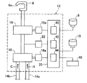
【解決手段】本発明は、流量又は温度を調整するための可動操作部(8,10)と、可動操作部(8,10)の操作に基づいて電気的に駆動される流量調整バルブ(18)又は湯水混合バルブ(16)とを備えた水栓装置(1)に関する。水栓装置(1)は、可動操作部(8,10)の移動速度又は回転速度をリアルタイムで検知する操作検知部(40)と、検知された移動速度又は回転速度に応じて流量又は温度の調整変化量割合を決定する変化量割合決定部(42)と、調整変化量割合に従って流量又は温度の調整設定値を決定する設定値決定部(44)と、調整設定値に対応して流量調整バルブ(18)又は湯水混合バルブ(16)を駆動する駆動部(16a,18a)を有する。
【選択図】図2
Description
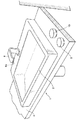
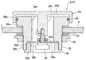
8、10 可動操作部
16 湯水混合バルブ(温度調整機構)
16a 駆動部
18 流量調整バルブ(流量調整機構)
18a 駆動部
40 操作検知部
42 変化量割合決定部
44 設定値決定部
46 表示部
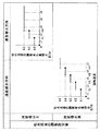
VH 上限速度
VL 下限速度
b1 下限調整変化量割合
b5 上限調整変化量割合
Claims (11)
- 流量又は温度を調整するための可動操作部と、可動操作部の操作に基づいて電気的に駆動される流量調整機構又は温度調整機構と、を備えた水栓装置であって、
前記可動操作部の移動速度又は回転速度をリアルタイムで検知する操作検知部と、
検知された移動速度又は回転速度に応じて流量又は温度の調整変化量割合を決定する変化量割合決定部と、
前記調整変化量割合に従って流量又は温度の調整設定値を決定する設定値決定部と、
前記調整設定値に対応して前記流量調整機構又は温度調整機構を駆動する駆動部と、を有し、
前記流量又は温度の調整変化量割合は、前記可動操作部の移動距離又は回転角度当たりの流量又は温度の変化量であることを特徴とする水栓装置。 - 前記変化量割合決定部は、前記移動速度又は回転速度が増大するにつれて前記調整変化量割合が減少しないように、前記調整変化量割合を決定することを特徴とする請求項1に記載の水栓装置。
- 前記変化量割合決定部は、前記移動速度又は回転速度が予め設定された上限速度よりも大きいとき、前記調整変化量割合を予め設定された一定の上限調整変化量割合に決定することを特徴とする請求項2に記載の水栓装置。
- 前記変化量割合決定部は、前記移動速度又は回転速度が予め設定された下限速度よりも小さいとき、前記調整変化量割合を予め設定された一定の下限調整変化量割合に決定することを特徴とする請求項2又は3に記載の水栓装置。
- 前記変化量割合決定部は、前記移動速度又は回転速度が増大するにつれて前記調整変化量割合を前記移動速度又は回転速度の1つの値において不連続的に増大させるように、前記調整変化量割合を決定することを特徴とする請求項2〜4の何れか1項に記載の水栓装置。
- 前記変化量割合決定部は、前記移動速度又は回転速度が増大するにつれて前記調整変化量割合を前記移動速度又は回転速度の複数の値において不連続的に増大させ且つ前記複数の値の間の移動速度又は回転速度において前記調整変化量割合を一定に保つように、前記調整変化量割合を決定することを特徴とする請求項2〜4の何れか1項に記載の水栓装置。
- 前記調整設定値が予め決められた流量又は温度の範囲内にあるとき、前記変化量割合決定部は、前記調整変化量割合を前記移動速度又は回転速度に関わらず予め決められた一定の調整変化量割合に決定することを特徴とする請求項1〜6の何れか1項に記載の水栓装置。
- 前記操作検知部は、前記可動操作部の移動方向が、流量又は温度を増大させる増大方向か、流量又は温度を減少させる減少方向かを検知し、
前記調整設定値が予め決められた一定の調整設定値よりも大きい場合において、前記変化量割合決定部は、前記可動操作部が増大方向に移動するときに前記調整変化量割合を予め決められた一定の調整変化量割合に決定し、前記可動操作部が減少方向に移動するときに前記調整変化量割合を前記移動速度又は回転速度に応じて変化するように決定することを特徴とする請求項1〜6の何れか1項に記載の水栓装置。 - 前記操作検知部は、前記可動操作部の移動方向が、流量又は温度を増大させる増大方向か、流量又は温度を減少させる減少方向かを検知し、
前記調整設定値が予め決められた流量又は温度の範囲内にある場合において、前記可動操作部が増大方向に移動するときに前記変化量割合決定部が決定する調整変化量割合と、前記可動操作部が減少方向に移動するときに前記変化量割合決定部が決定する調整変化量割合とが異なることを特徴とする請求項1〜6の何れか1項に記載の水栓装置。 - 更に、前記調整変化量割合が予め定められた一定の表示基準調整変化量割合よりも大きいことを表示する表示部を有することを特徴とする請求項1〜9の何れか1項に記載の水栓装置。
- 更に、前記調整変化量割合が前記上限調整変化量割合であることを表示する表示部を有することを特徴とする請求項3に記載の水栓装置。
Priority Applications (1)
| Application Number | Priority Date | Filing Date | Title |
|---|---|---|---|
| JP2008251101A JP5446029B2 (ja) | 2008-09-29 | 2008-09-29 | 水栓装置 |
Applications Claiming Priority (1)
| Application Number | Priority Date | Filing Date | Title |
|---|---|---|---|
| JP2008251101A JP5446029B2 (ja) | 2008-09-29 | 2008-09-29 | 水栓装置 |
Publications (2)
| Publication Number | Publication Date |
|---|---|
| JP2010084323A true JP2010084323A (ja) | 2010-04-15 |
| JP5446029B2 JP5446029B2 (ja) | 2014-03-19 |
Family
ID=42248560
Family Applications (1)
| Application Number | Title | Priority Date | Filing Date |
|---|---|---|---|
| JP2008251101A Expired - Fee Related JP5446029B2 (ja) | 2008-09-29 | 2008-09-29 | 水栓装置 |
Country Status (1)
| Country | Link |
|---|---|
| JP (1) | JP5446029B2 (ja) |
Cited By (2)
| Publication number | Priority date | Publication date | Assignee | Title |
|---|---|---|---|---|
| KR101866532B1 (ko) * | 2018-01-12 | 2018-06-11 | (주)제이바스 | 수전 장치 |
| KR101866531B1 (ko) * | 2018-01-12 | 2018-06-11 | (주)제이바스 | 수전 장치 |
Citations (3)
| Publication number | Priority date | Publication date | Assignee | Title |
|---|---|---|---|---|
| JPS6347577A (ja) * | 1986-08-15 | 1988-02-29 | Tokyo Keiki Co Ltd | ジヨイステツク操作入力による弁制御装置 |
| JPH0239584U (ja) * | 1988-09-06 | 1990-03-16 | ||
| JP2001208229A (ja) * | 2000-01-27 | 2001-08-03 | Inax Corp | 吐水器具 |
-
2008
- 2008-09-29 JP JP2008251101A patent/JP5446029B2/ja not_active Expired - Fee Related
Patent Citations (3)
| Publication number | Priority date | Publication date | Assignee | Title |
|---|---|---|---|---|
| JPS6347577A (ja) * | 1986-08-15 | 1988-02-29 | Tokyo Keiki Co Ltd | ジヨイステツク操作入力による弁制御装置 |
| JPH0239584U (ja) * | 1988-09-06 | 1990-03-16 | ||
| JP2001208229A (ja) * | 2000-01-27 | 2001-08-03 | Inax Corp | 吐水器具 |
Cited By (2)
| Publication number | Priority date | Publication date | Assignee | Title |
|---|---|---|---|---|
| KR101866532B1 (ko) * | 2018-01-12 | 2018-06-11 | (주)제이바스 | 수전 장치 |
| KR101866531B1 (ko) * | 2018-01-12 | 2018-06-11 | (주)제이바스 | 수전 장치 |
Also Published As
| Publication number | Publication date |
|---|---|
| JP5446029B2 (ja) | 2014-03-19 |
Similar Documents
| Publication | Publication Date | Title |
|---|---|---|
| US12249323B2 (en) | Electronic faucet with smart features | |
| US11015327B2 (en) | Electronic faucet with spatial orientation control system | |
| US10767354B2 (en) | Electronic faucet with smart features | |
| US20210335358A1 (en) | Electronic faucet with smart features | |
| CN1259604C (zh) | 电子混合水制备装置和制备混合水的方法 | |
| US10663075B2 (en) | Shower control system | |
| US20150258895A1 (en) | Method for controlling a functional device of a motor vehicle | |
| JP5446029B2 (ja) | 水栓装置 | |
| JP2009127379A (ja) | 電子制御水栓装置 | |
| JP5445337B2 (ja) | 給湯機 | |
| JPH05331888A (ja) | 湯水混合装置 | |
| JP2011226554A (ja) | 電動弁装置およびそれを用いた給湯機 | |
| JP5099598B2 (ja) | 水栓装置 | |
| JP5253279B2 (ja) | 流量調節装置 | |
| KR20110104359A (ko) | 이온수 생성기 유량조절장치 | |
| JP2010084325A (ja) | 水栓装置 | |
| KR101866531B1 (ko) | 수전 장치 | |
| JP2010084324A (ja) | 水栓装置 | |
| CN105627570A (zh) | 一种卫浴设备的多参数控制装置 | |
| JP2011252684A (ja) | 給湯機 | |
| JP5170841B2 (ja) | 水栓装置 | |
| KR101866532B1 (ko) | 수전 장치 | |
| JP2008144462A (ja) | 水栓 | |
| JP4775901B2 (ja) | 水栓装置 | |
| JP2025181218A (ja) | 水栓装置 |
Legal Events
| Date | Code | Title | Description |
|---|---|---|---|
| A621 | Written request for application examination |
Free format text: JAPANESE INTERMEDIATE CODE: A621 Effective date: 20110805 |
|
| A977 | Report on retrieval |
Free format text: JAPANESE INTERMEDIATE CODE: A971007 Effective date: 20121203 |
|
| A131 | Notification of reasons for refusal |
Free format text: JAPANESE INTERMEDIATE CODE: A131 Effective date: 20130603 |
|
| A521 | Written amendment |
Free format text: JAPANESE INTERMEDIATE CODE: A523 Effective date: 20130730 |
|
| TRDD | Decision of grant or rejection written | ||
| A01 | Written decision to grant a patent or to grant a registration (utility model) |
Free format text: JAPANESE INTERMEDIATE CODE: A01 Effective date: 20131202 |
|
| A61 | First payment of annual fees (during grant procedure) |
Free format text: JAPANESE INTERMEDIATE CODE: A61 Effective date: 20131215 |
|
| R150 | Certificate of patent or registration of utility model |
Ref document number: 5446029 Country of ref document: JP Free format text: JAPANESE INTERMEDIATE CODE: R150 Free format text: JAPANESE INTERMEDIATE CODE: R150 |
|
| LAPS | Cancellation because of no payment of annual fees |