JP2010083754A - Process for producing hydrogen with complete capture of co2 and recycling unconverted methane - Google Patents
Process for producing hydrogen with complete capture of co2 and recycling unconverted methane Download PDFInfo
- Publication number
- JP2010083754A JP2010083754A JP2009224062A JP2009224062A JP2010083754A JP 2010083754 A JP2010083754 A JP 2010083754A JP 2009224062 A JP2009224062 A JP 2009224062A JP 2009224062 A JP2009224062 A JP 2009224062A JP 2010083754 A JP2010083754 A JP 2010083754A
- Authority
- JP
- Japan
- Prior art keywords
- hydrogen
- steam
- adsorber
- stream
- range
- Prior art date
- Legal status (The legal status is an assumption and is not a legal conclusion. Google has not performed a legal analysis and makes no representation as to the accuracy of the status listed.)
- Granted
Links
Images


Classifications
-
- C—CHEMISTRY; METALLURGY
- C01—INORGANIC CHEMISTRY
- C01B—NON-METALLIC ELEMENTS; COMPOUNDS THEREOF; METALLOIDS OR COMPOUNDS THEREOF NOT COVERED BY SUBCLASS C01C
- C01B3/00—Hydrogen; Gaseous mixtures containing hydrogen; Separation of hydrogen from mixtures containing it; Purification of hydrogen
- C01B3/50—Separation of hydrogen or hydrogen containing gases from gaseous mixtures, e.g. purification
- C01B3/56—Separation of hydrogen or hydrogen containing gases from gaseous mixtures, e.g. purification by contacting with solids; Regeneration of used solids
-
- B—PERFORMING OPERATIONS; TRANSPORTING
- B01—PHYSICAL OR CHEMICAL PROCESSES OR APPARATUS IN GENERAL
- B01D—SEPARATION
- B01D53/00—Separation of gases or vapours; Recovering vapours of volatile solvents from gases; Chemical or biological purification of waste gases, e.g. engine exhaust gases, smoke, fumes, flue gases, aerosols
- B01D53/02—Separation of gases or vapours; Recovering vapours of volatile solvents from gases; Chemical or biological purification of waste gases, e.g. engine exhaust gases, smoke, fumes, flue gases, aerosols by adsorption, e.g. preparative gas chromatography
- B01D53/04—Separation of gases or vapours; Recovering vapours of volatile solvents from gases; Chemical or biological purification of waste gases, e.g. engine exhaust gases, smoke, fumes, flue gases, aerosols by adsorption, e.g. preparative gas chromatography with stationary adsorbents
-
- C—CHEMISTRY; METALLURGY
- C01—INORGANIC CHEMISTRY
- C01B—NON-METALLIC ELEMENTS; COMPOUNDS THEREOF; METALLOIDS OR COMPOUNDS THEREOF NOT COVERED BY SUBCLASS C01C
- C01B3/00—Hydrogen; Gaseous mixtures containing hydrogen; Separation of hydrogen from mixtures containing it; Purification of hydrogen
- C01B3/02—Production of hydrogen or of gaseous mixtures containing a substantial proportion of hydrogen
- C01B3/32—Production of hydrogen or of gaseous mixtures containing a substantial proportion of hydrogen by reaction of gaseous or liquid organic compounds with gasifying agents, e.g. water, carbon dioxide, air
- C01B3/34—Production of hydrogen or of gaseous mixtures containing a substantial proportion of hydrogen by reaction of gaseous or liquid organic compounds with gasifying agents, e.g. water, carbon dioxide, air by reaction of hydrocarbons with gasifying agents
- C01B3/48—Production of hydrogen or of gaseous mixtures containing a substantial proportion of hydrogen by reaction of gaseous or liquid organic compounds with gasifying agents, e.g. water, carbon dioxide, air by reaction of hydrocarbons with gasifying agents followed by reaction of water vapour with carbon monoxide
-
- C—CHEMISTRY; METALLURGY
- C01—INORGANIC CHEMISTRY
- C01B—NON-METALLIC ELEMENTS; COMPOUNDS THEREOF; METALLOIDS OR COMPOUNDS THEREOF NOT COVERED BY SUBCLASS C01C
- C01B3/00—Hydrogen; Gaseous mixtures containing hydrogen; Separation of hydrogen from mixtures containing it; Purification of hydrogen
- C01B3/50—Separation of hydrogen or hydrogen containing gases from gaseous mixtures, e.g. purification
- C01B3/52—Separation of hydrogen or hydrogen containing gases from gaseous mixtures, e.g. purification by contacting with liquids; Regeneration of used liquids
-
- B—PERFORMING OPERATIONS; TRANSPORTING
- B01—PHYSICAL OR CHEMICAL PROCESSES OR APPARATUS IN GENERAL
- B01D—SEPARATION
- B01D2253/00—Adsorbents used in seperation treatment of gases and vapours
- B01D2253/10—Inorganic adsorbents
- B01D2253/102—Carbon
-
- B—PERFORMING OPERATIONS; TRANSPORTING
- B01—PHYSICAL OR CHEMICAL PROCESSES OR APPARATUS IN GENERAL
- B01D—SEPARATION
- B01D2253/00—Adsorbents used in seperation treatment of gases and vapours
- B01D2253/30—Physical properties of adsorbents
- B01D2253/302—Dimensions
- B01D2253/304—Linear dimensions, e.g. particle shape, diameter
-
- B—PERFORMING OPERATIONS; TRANSPORTING
- B01—PHYSICAL OR CHEMICAL PROCESSES OR APPARATUS IN GENERAL
- B01D—SEPARATION
- B01D2253/00—Adsorbents used in seperation treatment of gases and vapours
- B01D2253/30—Physical properties of adsorbents
- B01D2253/302—Dimensions
- B01D2253/308—Pore size
-
- B—PERFORMING OPERATIONS; TRANSPORTING
- B01—PHYSICAL OR CHEMICAL PROCESSES OR APPARATUS IN GENERAL
- B01D—SEPARATION
- B01D2256/00—Main component in the product gas stream after treatment
- B01D2256/16—Hydrogen
-
- B—PERFORMING OPERATIONS; TRANSPORTING
- B01—PHYSICAL OR CHEMICAL PROCESSES OR APPARATUS IN GENERAL
- B01D—SEPARATION
- B01D2257/00—Components to be removed
- B01D2257/50—Carbon oxides
- B01D2257/502—Carbon monoxide
-
- B—PERFORMING OPERATIONS; TRANSPORTING
- B01—PHYSICAL OR CHEMICAL PROCESSES OR APPARATUS IN GENERAL
- B01D—SEPARATION
- B01D2257/00—Components to be removed
- B01D2257/50—Carbon oxides
- B01D2257/504—Carbon dioxide
-
- B—PERFORMING OPERATIONS; TRANSPORTING
- B01—PHYSICAL OR CHEMICAL PROCESSES OR APPARATUS IN GENERAL
- B01D—SEPARATION
- B01D2257/00—Components to be removed
- B01D2257/70—Organic compounds not provided for in groups B01D2257/00 - B01D2257/602
- B01D2257/702—Hydrocarbons
- B01D2257/7022—Aliphatic hydrocarbons
-
- B—PERFORMING OPERATIONS; TRANSPORTING
- B01—PHYSICAL OR CHEMICAL PROCESSES OR APPARATUS IN GENERAL
- B01D—SEPARATION
- B01D2259/00—Type of treatment
- B01D2259/40—Further details for adsorption processes and devices
- B01D2259/40083—Regeneration of adsorbents in processes other than pressure or temperature swing adsorption
- B01D2259/40088—Regeneration of adsorbents in processes other than pressure or temperature swing adsorption by heating
- B01D2259/4009—Regeneration of adsorbents in processes other than pressure or temperature swing adsorption by heating using hot gas
-
- C—CHEMISTRY; METALLURGY
- C01—INORGANIC CHEMISTRY
- C01B—NON-METALLIC ELEMENTS; COMPOUNDS THEREOF; METALLOIDS OR COMPOUNDS THEREOF NOT COVERED BY SUBCLASS C01C
- C01B2203/00—Integrated processes for the production of hydrogen or synthesis gas
- C01B2203/02—Processes for making hydrogen or synthesis gas
- C01B2203/0205—Processes for making hydrogen or synthesis gas containing a reforming step
- C01B2203/0227—Processes for making hydrogen or synthesis gas containing a reforming step containing a catalytic reforming step
- C01B2203/0233—Processes for making hydrogen or synthesis gas containing a reforming step containing a catalytic reforming step the reforming step being a steam reforming step
-
- C—CHEMISTRY; METALLURGY
- C01—INORGANIC CHEMISTRY
- C01B—NON-METALLIC ELEMENTS; COMPOUNDS THEREOF; METALLOIDS OR COMPOUNDS THEREOF NOT COVERED BY SUBCLASS C01C
- C01B2203/00—Integrated processes for the production of hydrogen or synthesis gas
- C01B2203/02—Processes for making hydrogen or synthesis gas
- C01B2203/0283—Processes for making hydrogen or synthesis gas containing a CO-shift step, i.e. a water gas shift step
-
- C—CHEMISTRY; METALLURGY
- C01—INORGANIC CHEMISTRY
- C01B—NON-METALLIC ELEMENTS; COMPOUNDS THEREOF; METALLOIDS OR COMPOUNDS THEREOF NOT COVERED BY SUBCLASS C01C
- C01B2203/00—Integrated processes for the production of hydrogen or synthesis gas
- C01B2203/04—Integrated processes for the production of hydrogen or synthesis gas containing a purification step for the hydrogen or the synthesis gas
- C01B2203/0415—Purification by absorption in liquids
-
- C—CHEMISTRY; METALLURGY
- C01—INORGANIC CHEMISTRY
- C01B—NON-METALLIC ELEMENTS; COMPOUNDS THEREOF; METALLOIDS OR COMPOUNDS THEREOF NOT COVERED BY SUBCLASS C01C
- C01B2203/00—Integrated processes for the production of hydrogen or synthesis gas
- C01B2203/04—Integrated processes for the production of hydrogen or synthesis gas containing a purification step for the hydrogen or the synthesis gas
- C01B2203/042—Purification by adsorption on solids
- C01B2203/043—Regenerative adsorption process in two or more beds, one for adsorption, the other for regeneration
-
- C—CHEMISTRY; METALLURGY
- C01—INORGANIC CHEMISTRY
- C01B—NON-METALLIC ELEMENTS; COMPOUNDS THEREOF; METALLOIDS OR COMPOUNDS THEREOF NOT COVERED BY SUBCLASS C01C
- C01B2203/00—Integrated processes for the production of hydrogen or synthesis gas
- C01B2203/04—Integrated processes for the production of hydrogen or synthesis gas containing a purification step for the hydrogen or the synthesis gas
- C01B2203/0465—Composition of the impurity
- C01B2203/0475—Composition of the impurity the impurity being carbon dioxide
-
- C—CHEMISTRY; METALLURGY
- C01—INORGANIC CHEMISTRY
- C01B—NON-METALLIC ELEMENTS; COMPOUNDS THEREOF; METALLOIDS OR COMPOUNDS THEREOF NOT COVERED BY SUBCLASS C01C
- C01B2203/00—Integrated processes for the production of hydrogen or synthesis gas
- C01B2203/08—Methods of heating or cooling
- C01B2203/0805—Methods of heating the process for making hydrogen or synthesis gas
- C01B2203/0811—Methods of heating the process for making hydrogen or synthesis gas by combustion of fuel
- C01B2203/0822—Methods of heating the process for making hydrogen or synthesis gas by combustion of fuel the fuel containing hydrogen
-
- C—CHEMISTRY; METALLURGY
- C01—INORGANIC CHEMISTRY
- C01B—NON-METALLIC ELEMENTS; COMPOUNDS THEREOF; METALLOIDS OR COMPOUNDS THEREOF NOT COVERED BY SUBCLASS C01C
- C01B2203/00—Integrated processes for the production of hydrogen or synthesis gas
- C01B2203/08—Methods of heating or cooling
- C01B2203/0805—Methods of heating the process for making hydrogen or synthesis gas
- C01B2203/0811—Methods of heating the process for making hydrogen or synthesis gas by combustion of fuel
- C01B2203/0827—Methods of heating the process for making hydrogen or synthesis gas by combustion of fuel at least part of the fuel being a recycle stream
-
- C—CHEMISTRY; METALLURGY
- C01—INORGANIC CHEMISTRY
- C01B—NON-METALLIC ELEMENTS; COMPOUNDS THEREOF; METALLOIDS OR COMPOUNDS THEREOF NOT COVERED BY SUBCLASS C01C
- C01B2203/00—Integrated processes for the production of hydrogen or synthesis gas
- C01B2203/12—Feeding the process for making hydrogen or synthesis gas
- C01B2203/1205—Composition of the feed
- C01B2203/1211—Organic compounds or organic mixtures used in the process for making hydrogen or synthesis gas
- C01B2203/1235—Hydrocarbons
- C01B2203/1241—Natural gas or methane
-
- C—CHEMISTRY; METALLURGY
- C01—INORGANIC CHEMISTRY
- C01B—NON-METALLIC ELEMENTS; COMPOUNDS THEREOF; METALLOIDS OR COMPOUNDS THEREOF NOT COVERED BY SUBCLASS C01C
- C01B2203/00—Integrated processes for the production of hydrogen or synthesis gas
- C01B2203/14—Details of the flowsheet
- C01B2203/148—Details of the flowsheet involving a recycle stream to the feed of the process for making hydrogen or synthesis gas
-
- Y—GENERAL TAGGING OF NEW TECHNOLOGICAL DEVELOPMENTS; GENERAL TAGGING OF CROSS-SECTIONAL TECHNOLOGIES SPANNING OVER SEVERAL SECTIONS OF THE IPC; TECHNICAL SUBJECTS COVERED BY FORMER USPC CROSS-REFERENCE ART COLLECTIONS [XRACs] AND DIGESTS
- Y02—TECHNOLOGIES OR APPLICATIONS FOR MITIGATION OR ADAPTATION AGAINST CLIMATE CHANGE
- Y02C—CAPTURE, STORAGE, SEQUESTRATION OR DISPOSAL OF GREENHOUSE GASES [GHG]
- Y02C20/00—Capture or disposal of greenhouse gases
- Y02C20/40—Capture or disposal of greenhouse gases of CO2
-
- Y—GENERAL TAGGING OF NEW TECHNOLOGICAL DEVELOPMENTS; GENERAL TAGGING OF CROSS-SECTIONAL TECHNOLOGIES SPANNING OVER SEVERAL SECTIONS OF THE IPC; TECHNICAL SUBJECTS COVERED BY FORMER USPC CROSS-REFERENCE ART COLLECTIONS [XRACs] AND DIGESTS
- Y02—TECHNOLOGIES OR APPLICATIONS FOR MITIGATION OR ADAPTATION AGAINST CLIMATE CHANGE
- Y02E—REDUCTION OF GREENHOUSE GAS [GHG] EMISSIONS, RELATED TO ENERGY GENERATION, TRANSMISSION OR DISTRIBUTION
- Y02E60/00—Enabling technologies; Technologies with a potential or indirect contribution to GHG emissions mitigation
- Y02E60/30—Hydrogen technology
- Y02E60/32—Hydrogen storage
-
- Y—GENERAL TAGGING OF NEW TECHNOLOGICAL DEVELOPMENTS; GENERAL TAGGING OF CROSS-SECTIONAL TECHNOLOGIES SPANNING OVER SEVERAL SECTIONS OF THE IPC; TECHNICAL SUBJECTS COVERED BY FORMER USPC CROSS-REFERENCE ART COLLECTIONS [XRACs] AND DIGESTS
- Y02—TECHNOLOGIES OR APPLICATIONS FOR MITIGATION OR ADAPTATION AGAINST CLIMATE CHANGE
- Y02P—CLIMATE CHANGE MITIGATION TECHNOLOGIES IN THE PRODUCTION OR PROCESSING OF GOODS
- Y02P20/00—Technologies relating to chemical industry
- Y02P20/10—Process efficiency
-
- Y—GENERAL TAGGING OF NEW TECHNOLOGICAL DEVELOPMENTS; GENERAL TAGGING OF CROSS-SECTIONAL TECHNOLOGIES SPANNING OVER SEVERAL SECTIONS OF THE IPC; TECHNICAL SUBJECTS COVERED BY FORMER USPC CROSS-REFERENCE ART COLLECTIONS [XRACs] AND DIGESTS
- Y02—TECHNOLOGIES OR APPLICATIONS FOR MITIGATION OR ADAPTATION AGAINST CLIMATE CHANGE
- Y02P—CLIMATE CHANGE MITIGATION TECHNOLOGIES IN THE PRODUCTION OR PROCESSING OF GOODS
- Y02P20/00—Technologies relating to chemical industry
- Y02P20/151—Reduction of greenhouse gas [GHG] emissions, e.g. CO2
-
- Y—GENERAL TAGGING OF NEW TECHNOLOGICAL DEVELOPMENTS; GENERAL TAGGING OF CROSS-SECTIONAL TECHNOLOGIES SPANNING OVER SEVERAL SECTIONS OF THE IPC; TECHNICAL SUBJECTS COVERED BY FORMER USPC CROSS-REFERENCE ART COLLECTIONS [XRACs] AND DIGESTS
- Y02—TECHNOLOGIES OR APPLICATIONS FOR MITIGATION OR ADAPTATION AGAINST CLIMATE CHANGE
- Y02P—CLIMATE CHANGE MITIGATION TECHNOLOGIES IN THE PRODUCTION OR PROCESSING OF GOODS
- Y02P30/00—Technologies relating to oil refining and petrochemical industry
Abstract
Description
本発明は、水素製造の分野に関し、より特定的には、CO2の完全な捕捉を伴って水素を製造し、未転化メタンを再循環させる方法に関する。 The present invention relates to the field of hydrogen production, and more particularly to a process for producing hydrogen with complete capture of CO 2 and recycling unconverted methane.
国際科学界により工業時代以来観察された地球温暖化は、地球の多くの領域の気候および生態系を劇的に改変し得る。温室効果ガスの放出、特に二酸化炭素(CO2)が、この温暖化の原因であるように思われる。 Global warming observed since the industrial era by the international scientific community can dramatically alter the climate and ecosystems of many areas of the globe. It seems that greenhouse gas emissions, especially carbon dioxide (CO 2 ), are responsible for this warming.
化石燃料(天然ガス、石油、石炭)は、地球上の即時利用可能な燃料の大部分を構成する。しかしながら、そのような化石燃料は、用いられた場合、CO2を生じさせ(一般的には、燃焼工程の間)、それ故に、地球温暖化に寄与する。 Fossil fuels (natural gas, oil, coal) constitute the majority of the ready-to-use fuels on earth. However, such fossil fuels, when used, produce CO 2 (generally during the combustion process) and therefore contribute to global warming.
温室効果ガス放出による地球温暖化と闘う一つの推奨解決策は、生じたCO2を捕捉し、次いで、それを地下に貯蔵することである。化石燃料を水素に転化し、同時に生じたCO2の捕捉および貯蔵することからなる予備燃焼による捕捉を含めて、多くの可能性が調査された。水素(エネルギー担体(energy vector))は、温室効果ガスを排出することなく自由に燃やされ得る。 One recommended solution to combat global warming due to greenhouse gas emissions is to capture the resulting CO 2 and then store it underground. Many possibilities were investigated, including pre-combustion capture, which consists of converting fossil fuels to hydrogen and simultaneously capturing and storing the CO 2 produced. Hydrogen (energy vector) can be freely burned without exhausting greenhouse gases.
現在、化石燃料から水素を工業スケールで製造するために複数の方法がある。最も一般的な方法は、炉において行われる水蒸気改質天然ガス(SMR:steam methane reforming)であり、これは、その組成物の高いメタン含有量のために高い水素/炭素比を有する供給材料を用いるという利点を有している。簡易化した方法で、接触SMR反応は、以下のように記述され得る: There are currently several methods for producing hydrogen from fossil fuels on an industrial scale. The most common method is steam methane reforming (SMR) carried out in a furnace, which uses a feedstock with a high hydrogen / carbon ratio due to the high methane content of the composition. It has the advantage of using. In a simplified manner, the contact SMR reaction can be described as follows:
![]()
![]()
この高い吸熱反応は平衡化される。高温によって有利とされ、一般的には、天然ガス等の燃料によって加熱された炉において行われる。従来、SMR装置の次には、水蒸気転化の工程(WGS:water gas shift)が行われ、これは、以下の反応によって水素製造を最大にし得る。 This high endothermic reaction is equilibrated. It is advantageous due to the high temperature and is generally carried out in a furnace heated by a fuel such as natural gas. Conventionally, the SMR apparatus is followed by a water gas shift (WGS) process, which can maximize hydrogen production by the following reaction.
![]()
![]()
貯蔵のためにCO2が捕捉されるべき時には、水素リッチな流れからCO2を抽出することになるアミン洗浄装置(例えば、活性化MDEA)を用いることが可能であり、水素リッチな流れは、次いで、例えば、発電のためにガスタービンに送られる一方で、CO2は、圧縮されて地下に送られる。 When CO 2 is to be captured for storage, an amine scrubber (eg, activated MDEA) can be used that will extract CO 2 from the hydrogen rich stream, where the hydrogen rich stream is The CO 2 is then compressed and sent underground, for example, while being sent to a gas turbine for power generation.
当該タイプの方法ではCO2を捕捉する目的は全く達成されない。水素中に依然として存在するメタン、COおよびCO2の存在に起因してタービンの出口にCO2が依然として残るだけでなく、それがタービンに直接的に送られるためにより多くの天然ガスが入口において必要とされるからである。さらに、水蒸気改質が行われる炉は、天然ガスを用い、それ故に、多量のCO2を排出する。CO2の隔離比はそれ故に低い。 With this type of method, the purpose of capturing CO 2 is not achieved at all. Not only does CO 2 still remain at the turbine outlet due to the presence of methane, CO and CO 2 still present in the hydrogen, but more natural gas is needed at the inlet because it is sent directly to the turbine It is because it is said. Furthermore, furnaces in which steam reforming takes place use natural gas and therefore emit a large amount of CO 2 . The CO 2 sequestration ratio is therefore low.
当該技術に対する一つの改善は、不純物吸着のために圧力変調モレキュラーシーブを用いる吸着装置を加えることからなる(PSA)。2つの流れが現在得られている:99.99%の高純度水素流れおよび少なくとも20%の水素を含有する不純物の流れである。この低圧力の流れは、水蒸気改質炉のためのバーナーに送られ、これにより、炉に必要な天然ガスの量が低減させられ、それ故に、CO2が生成する。しかしながら、CO2の隔離比は低いままである。若干の不純物が炉の煙霧中にCO2の形態で出ることになり、さらに、より多くの水素が製造される必要があり、それ故に、より多くの天然ガスが、水蒸気改質供給材料用に用いられなければならないからである。 One improvement to the technology consists of adding an adsorption device that uses pressure-modulated molecular sieves for impurity adsorption (PSA). Two streams are currently available: a 99.99% high purity hydrogen stream and an impurity stream containing at least 20% hydrogen. This low pressure stream is sent to a burner for the steam reforming furnace, thereby, the amount of natural gas is reduced required furnace, therefore, CO 2 is produced. However, the CO 2 sequestration ratio remains low. Some impurities will be leaving in the form of CO 2 in the fumes of the furnace, furthermore, it is necessary that more hydrogen is produced, therefore, more natural gas, for steam reforming feed This is because it must be used.
それ故に、本発明の目的は、製造終了時に存在する不純物、特にメタンを捕捉し、かつ、エネルギー損失なしでそれらを水蒸気改質工程に再循環させ得る水素製造方法を提案することによって従来技術の不利益点の1以上を克服することである。 Therefore, the object of the present invention is to provide a hydrogen production method that can capture impurities present at the end of production, in particular methane, and recycle them to the steam reforming process without energy loss. Overcoming one or more of the disadvantages.
この目的のため、本発明は、炭化水素供給材料および水蒸気から水素を製造する方法であって、
・水蒸気の存在下、炭化水素供給材料を水蒸気改質するための装置において合成ガスを製造する工程であって、燃料が反応に必要な熱を提供する、工程と、
・先行工程において得られた合成ガスを水蒸気転化する工程であって、メタンおよび二酸化炭素を含有する水素の流れを製造する、工程と、
・水蒸気転化工程から得られた流れ中に存在する二酸化炭素を捕捉して、水素の流れから二酸化炭素を分離する工程と、
水素流れ中に存在するメタンおよび他の不純物を捕捉しかつこれを水蒸気改質工程に再循環させる工程と
を包含する方法を提案する。
For this purpose, the present invention is a process for producing hydrogen from a hydrocarbon feed and steam,
A process for producing synthesis gas in an apparatus for steam reforming a hydrocarbon feed in the presence of steam, wherein the fuel provides the heat required for the reaction;
A process for steam conversion of the synthesis gas obtained in the preceding process, producing a stream of hydrogen containing methane and carbon dioxide;
Capturing carbon dioxide present in the stream obtained from the steam conversion process and separating the carbon dioxide from the hydrogen stream;
A process is proposed that includes capturing methane and other impurities present in the hydrogen stream and recycling it to the steam reforming process.
本発明の一つの実施によると、炭化水素供給材料は天然ガスである。 According to one implementation of the present invention, the hydrocarbon feed is natural gas.
本発明の水素製造方法において、不純物の捕捉・再循環の工程は、少なくとも2つの吸着器(adsorber)を含む吸着装置において行われ、少なくとも以下の段階を連続して含む:
・第1の吸着装置上での不純物の吸着;
・第1の吸着装置の再生および第2の吸着装置上での不純物の吸着。
In the hydrogen production method of the present invention, the process of trapping and recycling impurities is performed in an adsorption apparatus including at least two adsorbers, and continuously includes at least the following steps:
The adsorption of impurities on the first adsorption device;
Regeneration of the first adsorption device and adsorption of impurities on the second adsorption device.
本発明の一つの実施形態によると、吸着器の再生段階は、以下のようにして行われる:
・飽和した時に吸着器を分離し、かつ、第2の吸着器を作動状態にする;
・第1の吸着器に、炭化水素供給材料の流れであって、水蒸気改質装置のための供給材料として働かせることを目的とし、水蒸気(これも水蒸気改質装置を目的とする)との交換によって水蒸気の凝結温度より少なくとも20℃高い温度まで加熱された、ものを流す;
・水蒸気改質装置を目的として少なくとも20℃過熱された水蒸気を流通させることによって加熱された吸着器を再生し、不純物を脱着させる;
・吸着器に高純度の熱水素の流れを流すことによって再生された吸着器中に存在する水蒸気を除去する;
水蒸気を含まない吸着器に高純度の冷水素の流れを流す。
According to one embodiment of the invention, the regeneration stage of the adsorber is performed as follows:
Separating the adsorber when saturated and bringing the second adsorber into operation;
• The first adsorber is a flow of hydrocarbon feed, intended to serve as feed for a steam reformer, and exchanged with steam (also for steam reformer) Flowing one that has been heated to a temperature at least 20 ° C. above the condensation temperature of the water vapor;
-Regenerate the heated adsorber by dewatering impurities by circulating steam heated at least 20 ° C for the purpose of a steam reformer;
Removing water vapor present in the regenerated adsorber by flowing a flow of high purity hot hydrogen through the adsorber;
A high purity cold hydrogen stream is passed through an adsorber that does not contain water vapor.
本発明の一つの実施において、不純物を吸着させる工程は、20〜100℃の範囲の温度で行われる。 In one implementation of the invention, the step of adsorbing impurities is performed at a temperature in the range of 20-100 ° C.
本発明の一つの実施において、吸着工程は、活性炭または炭素(carbon)モレキュラーシーブタイプの吸着剤により行われる。 In one implementation of the present invention, the adsorption step is performed with an activated carbon or carbon molecular sieve type adsorbent.
本発明の一つの実施によると、吸着工程は、物理的水蒸気活性化によって調製された木炭(charcoal)により行われる。 According to one implementation of the present invention, the adsorption step is performed with charcoal prepared by physical steam activation.
本発明の一つの実施によると、吸着工程は、2nm未満の径を有するミクロ孔、50nm超の径を有するマクロ孔およびより少ない量の2〜50nmの径を有するメソ孔を含有する活性炭により行われる。 According to one implementation of the invention, the adsorption step is performed with activated carbon containing micropores having a diameter of less than 2 nm, macropores having a diameter of more than 50 nm, and smaller amounts of mesopores having a diameter of 2-50 nm. Is called.
本発明の水素製造方法において、吸着された不純物は、メタン、二酸化炭素および一酸化炭素である。 In the hydrogen production method of the present invention, the adsorbed impurities are methane, carbon dioxide and carbon monoxide.
本発明の一つの実施によると、再生された吸着器に流した後に得られた水蒸気で飽和した熱水素の流れの一部は、改質装置用のバーナーに送られ、流れの他の部分は、希釈水蒸気との混合物として発電のためにガスタービンに送られる。 According to one implementation of the present invention, a portion of the steam-saturated hot hydrogen stream obtained after flowing through the regenerated adsorber is sent to the reformer burner and the other portion of the stream is And sent to the gas turbine for power generation as a mixture with diluted steam.
本発明の一つの実施によると、再生された吸着器に流した後に得られた冷水素の流れの一部は、外部装置に送られる一方で、水素の残りは、熱洗流(flushing)のために用いられ、次いで、改質装置のバーナーに送られる。 According to one implementation of the invention, a portion of the cold hydrogen stream obtained after flowing through the regenerated adsorber is sent to an external device, while the remainder of the hydrogen is fed into a hot flushing. And then sent to the reformer burner.
本発明の一つの実施によると、吸着器冷却段階後に得られた加熱された水素の流れは、水蒸気との交換によって再加熱され、吸着器中に存在する水蒸気を除去する段階において用いられる。 According to one implementation of the present invention, the heated hydrogen stream obtained after the adsorber cooling stage is reheated by exchange with water vapor and used in the stage of removing water vapor present in the adsorber.
本発明の一つの実施によると、合成ガス製造工程は、2.5〜3.5MPaの範囲の圧力で行われる。 According to one implementation of the present invention, the synthesis gas production process is performed at a pressure in the range of 2.5 to 3.5 MPa.
本発明の一つの実施によると、二酸化炭素の捕捉工程は、メチルジエチルアミンおよび少なくとも1種の他のアミンを用いるアミン装置において行われる。 According to one implementation of the invention, the carbon dioxide capture step is performed in an amine unit using methyldiethylamine and at least one other amine.
本発明の他の特徴および利点は、添付の図面を参照してなされ、かつ例として与えられた以下の記載からより良好に理解され、かつ、より明らかにされることになる。 Other features and advantages of the present invention will be better understood and more apparent from the following description, made by reference to the accompanying drawings and given by way of example.
本発明は、炭化水素供給材料および水蒸気から水素を製造する方法であって、
・水蒸気の存在下に炭化水素供給材料を水蒸気改質するための装置において合成ガスを製造する工程であって、燃料が、反応に必要な熱を提供する、工程と、
・先行工程において得られた合成ガスを水蒸気転化し、メタンおよび二酸化炭素を含有する水素の流れを生じさせる工程と、
・水蒸気転化工程から得られた流れの中に存在する二酸化炭素を捕捉して、水素の流れから二酸化炭素を分離する工程と、
・水素の流れの中に存在するメタンおよび他の不純物(CO、CO2)を捕捉し、これを水蒸気改質工程に再循環させる工程と
を包含する方法であり、これにより、製造終了時に存在する不純物、特にメタンを捕捉し、かつ、エネルギー損失なしでそれらを水蒸気改質工程に再循環させることができる。
The present invention is a process for producing hydrogen from a hydrocarbon feedstock and steam comprising:
Producing syngas in an apparatus for steam reforming a hydrocarbon feed in the presence of steam, wherein the fuel provides the heat necessary for the reaction;
A step of steam-converting the synthesis gas obtained in the preceding step to produce a flow of hydrogen containing methane and carbon dioxide;
Capturing carbon dioxide present in the stream obtained from the steam conversion process and separating the carbon dioxide from the hydrogen stream;
Captures methane and other impurities (CO, CO 2 ) present in the hydrogen stream and recirculates them to the steam reforming process, thereby presenting at the end of production Impurities, particularly methane, can be captured and recycled to the steam reforming process without energy loss.
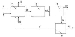
図1、2および3において見られ得るように、水素を製造する方法の間、ライン(1)中を移動する天然ガスの流れおよびライン(2)中を移動する水蒸気の流れは、供給材料として水蒸気改質装置(11)に送られる。反応に必要な熱は、燃料、例えば、天然ガスの流れによって作られ、ライン(10)を介して水蒸気改質炉に送られる。この反応は、炉出口(110)において炭酸性(carbonic)のガスを含有する煙霧の流れを生じさせる。水蒸気改質反応によって得られたライン(30)中を移動する合成ガスの流れは、主に、水素(H2)、一酸化炭素(CO)、二酸化炭素(CO2)並びに反応が平衡化されているので水蒸気(H2O)および少量の未反応メタン(CH4)を含有し、また、900℃の温度において、約4%の未反応メタンが残る。この合成ガスの流れは、ライン(30)を介して水蒸気転化装置(12)に送られる。この装置において、大抵の一酸化炭素は、水蒸気を用いて二酸化炭素に転化され、同時に、もう少しの水素を遊離させる。この反応も平衡化され、終了時に、少量の一酸化炭素が残る(高い転化率条件下に0.5%)。転化装置(12)からの出口において、ライン(40)中を移動する得られた転化流れは、本質的に、水素および二酸化炭素を含有する。ライン(40)中を移動するこの流れも、少量のメタンおよび一酸化炭素を含有し、水蒸気の残りは、水蒸気改質反応器の後ろで凝結させられる。 As can be seen in FIGS. 1, 2 and 3, during the process for producing hydrogen, the stream of natural gas traveling in line (1) and the stream of water vapor traveling in line (2) are used as feeds. It is sent to the steam reformer (11). The heat required for the reaction is produced by the flow of fuel, for example natural gas, and sent to the steam reformer via line (10). This reaction produces a stream of fumes containing carbonic gas at the furnace outlet (110). Flow of synthesis gas moving the resulting line (30) medium by the steam reforming reaction is mainly hydrogen (H 2), carbon monoxide (CO), carbon dioxide (CO 2) as well as the reaction is equilibrated Therefore, it contains water vapor (H 2 O) and a small amount of unreacted methane (CH 4 ), and at a temperature of 900 ° C., about 4% of unreacted methane remains. This synthesis gas stream is sent to the steam converter (12) via the line (30). In this apparatus, most carbon monoxide is converted to carbon dioxide using water vapor and at the same time liberates some more hydrogen. This reaction is also equilibrated and at the end a small amount of carbon monoxide remains (0.5% under high conversion conditions). The resulting conversion stream traveling in line (40) at the outlet from the converter (12) essentially contains hydrogen and carbon dioxide. This stream traveling in line (40) also contains a small amount of methane and carbon monoxide and the remainder of the steam is condensed behind the steam reforming reactor.
転化流れは、次いで、CO2捕捉装置(13)に送られる。CO2捕捉装置(13)は、アミン装置であってよい;メチルジエチルアミン(MDEA)を少なくとも1種の他のアミンと組み合わせて用いるアミン装置が特に適している。当業者に周知である他のCO2捕捉装置を用いることが可能である。 The conversion stream is then sent to a CO 2 capture device (13). The CO 2 capture device (13) may be an amine device; amine devices that use methyldiethylamine (MDEA) in combination with at least one other amine are particularly suitable. Other CO 2 capture devices well known to those skilled in the art can be used.
CO2の本質的な部分は分離され、再注入の場所、例えば、排気領域または適切な地層への後の輸送のためにライン(50)を介して圧縮・乾燥装置に送られる。 An essential part of the CO 2 is separated and sent to the compression and drying device via line (50) for later transport to a re-injection site, such as the exhaust region or appropriate formation.
水素リッチなガスは、別のライン(60)を介して排出される。このガスは、少量のメタン、一酸化炭素および少量の捕捉されなかった二酸化炭素(約0.5%)を含む。 Hydrogen rich gas is exhausted via a separate line (60). This gas contains a small amount of methane, carbon monoxide and a small amount of untrapped carbon dioxide (about 0.5%).
本発明の方法では、この水素リッチなガスは、活性炭吸着装置(15)に向けられるが、これは、モレキュラーシーブ(14)上で圧力調節(PSA法)により不純物を吸着する装置の方に向けられる従来技術とは対照的である。この従来技術の場合99.99%の高純度の水素が、ライン(70)を介して排出れる一方で、約20%の水素が、不純物の全てと共にパージ(8)に送られる(図2)。 In the method of the present invention, this hydrogen-rich gas is directed to the activated carbon adsorber (15), which is directed towards an apparatus that adsorbs impurities by pressure regulation (PSA method) on the molecular sieve (14). This is in contrast to the prior art. In this prior art, 99.99% high purity hydrogen is discharged via line (70), while about 20% hydrogen is sent to purge (8) along with all of the impurities (FIG. 2). .
本発明の方法において用いられる吸着装置(15)(それ故に、例えば、活性炭または下記実施例において記載される任意の他の固体吸着剤上で操作され得る)において、ライン(2)を介して供給された水蒸気を用いて高圧力で再生が行われる。この水蒸気は、次いで、ライン(90)を介して供給される水蒸気改質装置のための供給材料として用いられる。不純物(CH4、CO、CO2)は、それ故に、水蒸気改質反応器に再循環させられる。水蒸気改質炉によってCO2を放出させないために、ライン(70)を介して出る生じた水素の一部は、水蒸気改質装置において用いられる。ライン(70)からの水素の一部は、それ故に、水蒸気改質装置のためにライン(10)を介してバーナーに送られ、その結果、ライン(110)を介して出る煙霧は、CO2を含有していない。水素の残りは、ライン(80)を介してガスタービン(16)に送られ、ライン(17)を介して到着する希釈水蒸気と混合される。この構成において、CO2隔離比は、100%近くであり得る。 Supplied via line (2) in the adsorption device (15) used in the process of the present invention (and therefore can be operated, for example, on activated carbon or any other solid adsorbent described in the examples below) Regeneration is performed at a high pressure using the generated water vapor. This steam is then used as a feed for the steam reformer supplied via line (90). Impurities (CH 4 , CO, CO 2 ) are therefore recycled to the steam reforming reactor. In order not to release CO 2 by the steam reforming furnace, a portion of the hydrogen generated via line (70) is used in the steam reformer. Part of the hydrogen from line (70) is therefore sent to the burner via line (10) for the steam reformer, so that the fumes exiting via line (110) become CO 2 Does not contain. The remainder of the hydrogen is sent to the gas turbine (16) via line (80) and mixed with the diluted steam arriving via line (17). In this configuration, the CO 2 sequestration ratio can be close to 100%.
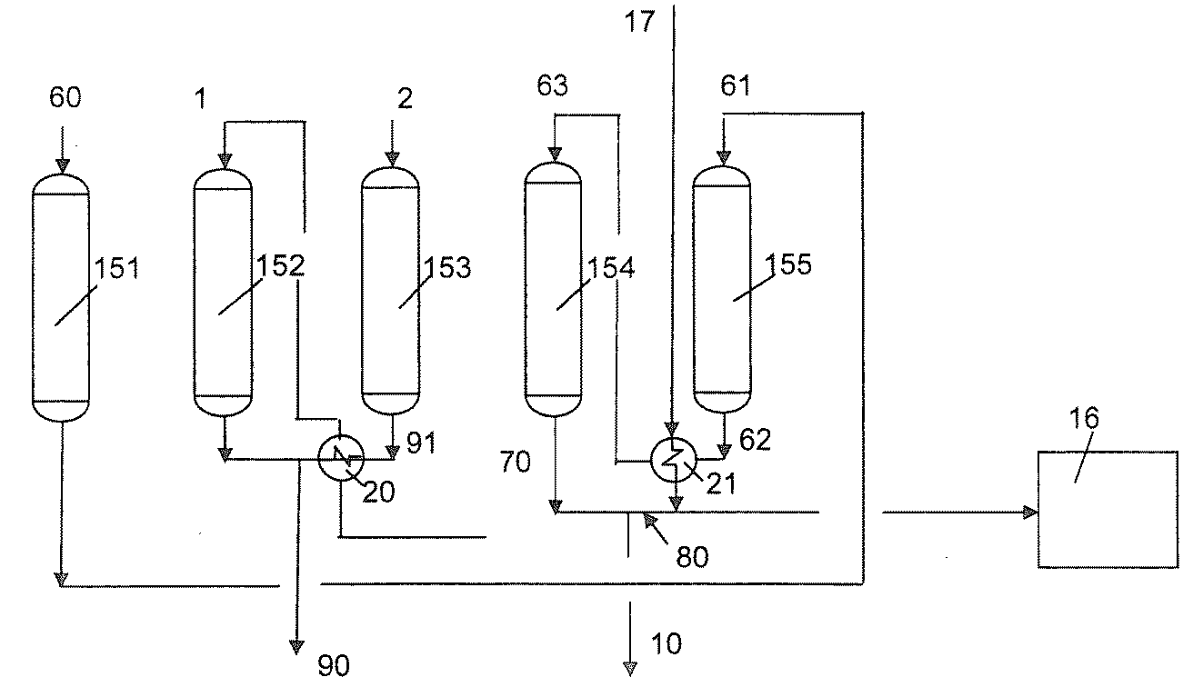
本発明において用いられる吸着装置(15)は、容量器(capacity)とも称される複数の吸着器(151)〜(155)によって構成される。操作態様は、図4において、5つの吸着器を有する構成で例証されるが、この構成は、制限的ではない。この吸着装置は、次のパージおよび加圧段階に必要な供給材料メタンをライン(1)を介して供給される。本発明の範囲を逸脱することなく種々の数、例えば5〜10個の容量器が明らかに可能であるが、本発明者らは自ら、本発明をより単純に説明するために5に制限した。 The adsorption device (15) used in the present invention includes a plurality of adsorbers (151) to (155), which are also referred to as capacitors. Although the mode of operation is illustrated in FIG. 4 with a configuration having five adsorbers, this configuration is not limiting. The adsorber is fed via line (1) with the feed methane required for the next purge and pressurization stage. Various numbers, e.g., 5-10 capacitors, are clearly possible without departing from the scope of the invention, but the inventors themselves limited to 5 to more simply describe the invention. .
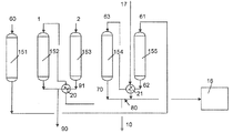
吸着装置(15)における吸着サイクルは、複数の段階によって構成される。5つの容量器(151)〜(155)は吸着剤により充填される。ライン(60)を介して到着する精製されるべき水素リッチなガスの流れは、第1の容量器(151)に20〜100℃の範囲、好ましくは40〜80℃の範囲、より好ましくは30〜70℃の範囲の温度で送られる。この流れ中に含まれるメタン、COおよびCO2は、吸着剤上で捕捉され、精製された水素は、ライン(61)を介して出る。ライン(61)中を移動する水素は、次いで、第5の容量器(155)に送られて、それは、20〜100℃の範囲である操作温度に冷却される。加熱された水素は、ライン(62)を介して第5の容量器を出、熱交換器(21)に送られ、ライン(17)を介して到着する希釈水蒸気との交換によってさらに加熱される。熱水素は、ライン(63)を介して操作圧力における水蒸気の凝結温度より少なくとも20℃高い温度で熱交換器(21)を出る。ライン(63)を介して第4の容量器(154)に供給される熱水素は、再生工程後に容量器中に残っている水蒸気を排出し得る。この水蒸気の一部は、水素との混合物として水蒸気改質バーナーのバーナーにライン(10)を介して送られ、一部は、ライン(80)を介してガスタービン(16)に送られる。図12において例証される変形例において、ライン(62)中を移動する水素の一部は、容量器(155)からの出口において取り出され、冷却水または空気を用いる熱交換器(23)によって冷却され、圧縮機(24)によって圧縮される。それ故に、高純度水素の流れは、例えば、外部消費者の外部装置にライン(15)を介して送られる。ライン(62)からの水素の残りは、交換器(21)によって加熱された後に、容量器(154)に流され、ライン(70)を介してこの容量器を出、次いで、希釈水蒸気(17)と混合され、交換器(21)によって冷却され、ライン(10)を介して燃料として水蒸気改質炉に送られる。 The adsorption cycle in the adsorption device (15) is constituted by a plurality of stages. The five capacitors (151) to (155) are filled with the adsorbent. The hydrogen-rich gas stream to be purified arriving via line (60) is in the range of 20-100 ° C., preferably in the range of 40-80 ° C., more preferably 30 in the first condenser (151). Sent at a temperature in the range of ~ 70 ° C. Methane, CO and CO 2 contained in this stream are trapped on the adsorbent and purified hydrogen exits via line (61). The hydrogen traveling in line (61) is then sent to a fifth capacitor (155), where it is cooled to an operating temperature that is in the range of 20-100 ° C. The heated hydrogen exits the fifth capacitor via line (62), is sent to the heat exchanger (21), and is further heated by exchange with diluted steam arriving via line (17). . Hot hydrogen leaves the heat exchanger (21) via line (63) at a temperature at least 20 ° C. above the condensation temperature of water vapor at the operating pressure. The hot hydrogen supplied to the fourth capacitor (154) via the line (63) can discharge water vapor remaining in the capacitor after the regeneration process. Part of this steam is sent as a mixture with hydrogen to the burner of the steam reforming burner via line (10), and part is sent to gas turbine (16) via line (80). In the variation illustrated in FIG. 12, a portion of the hydrogen traveling in line (62) is removed at the outlet from the condenser (155) and cooled by a heat exchanger (23) using cooling water or air. And compressed by the compressor (24). Thus, the high purity hydrogen stream is routed, for example, via line (15) to an external device of an external consumer. The remainder of the hydrogen from the line (62) is heated by the exchanger (21) and then flows to the capacitor (154), exits the capacitor via the line (70), and then dilute steam (17 ), Cooled by the exchanger (21), and sent to the steam reforming furnace as fuel via the line (10).
第3の容量器(153)は、ライン(2)を介して供給された水蒸気を流される。メタンおよびCO2により満たされた水蒸気は、第3の容量器(153)からライン(91)を介して排出され、第2の熱交換器(20)においてライン(1)を介して到着する天然ガスとの交換によってわずかに冷却され、次いで、第2の容量器(152)から来る天然ガスと混合され、次いで、ライン(90)を介して水蒸気改質装置に送られる。 The third capacitor (153) is fed with water vapor supplied via the line (2). The water vapor filled with methane and CO 2 is discharged from the third condenser (153) via line (91) and arrives via the line (1) in the second heat exchanger (20). Slightly cooled by exchange with gas, then mixed with natural gas coming from the second capacitor (152) and then sent to the steam reformer via line (90).
第2の容量器(152)は、最初に、天然ガスの圧力(これは、約3.5MPaである)にされ、次いで、ライン(91)を介して供給された水蒸気との交換によって予備加熱した後にライン(1)を介して到着する熱天然ガス(250〜350℃)を流すことによって徐々に加熱される。 The second condenser (152) is first brought to the pressure of natural gas (which is about 3.5 MPa) and then preheated by exchange with steam supplied via line (91). And then gradually heated by flowing hot natural gas (250-350 ° C.) arriving via line (1).
図5は、容量器または吸着器の一つ、例えば、第1のもの(151)を示し、これは、活性炭であり得る吸着剤物質を含んでいる。精製されるべき水素、天然ガス、水蒸気、高純度の熱水素および高純度の冷水素をそれぞれ供給するライン(60)、(1)、(2)、(63)および(61)は、弁により容量器に接続され、これは、回路のそれぞれは分離され得ることを意味する。それぞれ、高純度の冷水素、メタンを水蒸気改質装置に、水蒸気を水蒸気改質装置に、水蒸気で飽和した高純度水素および高純度の水素を排出する、ライン(61)、(90)、(91)、(70)および(62)はまた、隔離弁を有する容量器に接続される。 FIG. 5 shows one of the capacitors or adsorbers, for example the first one (151), which contains an adsorbent material which can be activated carbon. Lines (60), (1), (2), (63) and (61) for supplying hydrogen to be purified, natural gas, steam, high purity hot hydrogen and high purity cold hydrogen, respectively, are controlled by valves. Connected to a capacitor, which means that each of the circuits can be isolated. Lines (61), (90), (90), which discharge high purity cold hydrogen, methane into a steam reformer, steam into a steam reformer, high purity hydrogen saturated with steam and high purity hydrogen, respectively. 91), (70) and (62) are also connected to a capacitor having an isolation valve.
この図では単純化のため、本発明者らは、容量器の頂部において入来流れの全ての入口を示し、全ての出口は底部にあるが、これは、単なる一つの可能性であり、本発明の範囲から逸脱することなく任意の他の構成が可能である。 In this figure, for simplicity, we show all the inlets of the incoming flow at the top of the capacitor and all the outlets at the bottom, but this is just one possibility, this Any other configuration is possible without departing from the scope of the invention.
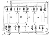
図6は、5つの容量器または吸着器(151、152、153、154および155)の平行な配列を示し、これは、装置は、連続的に操作され得ることを意味する。この場合にも、本発明の範囲から逸脱することなく種々の数の容量器が明らかに可能であるが、本発明者らは自ら、本発明をより単純に説明し得るように5つに制限した。 FIG. 6 shows a parallel arrangement of five capacitors or adsorbers (151, 152, 153, 154 and 155), which means that the device can be operated continuously. Again, various numbers of capacitors are clearly possible without departing from the scope of the present invention, but the inventors themselves limited to five so that the present invention can be described more simply. did.
図7は、吸着サイクルの操作の第1段階を示す。固体弁(黒)は閉じられ、他は開いている。第1の容量器(151)は、ライン(60)を介して低温の純粋でない水素を受け、種々の不純物を吸着剤上に保有し、高純度の水素はライン(61)を出る。第2の容量器(152)は、丁度回路から取り出され、再生が開始されている。第1に、ライン(1)を介して到着する熱メタンを用いて加圧が行われ、次いで、吸着剤は、メタンによって、250〜350℃の範囲の温度に加熱され、その結果、その時に再生のために用いられる水蒸気が外で凝結するだろう危険性はない(水の蒸気張力は約225℃において2.5MPa、約245℃において3.5MPa)。吸着剤を出るメタンは、ライン(90)を介して水蒸気改質装置に送られる。 FIG. 7 shows the first stage of operation of the adsorption cycle. The solid valve (black) is closed and the others are open. The first capacitor (151) receives the low temperature impure hydrogen via line (60) and carries various impurities on the adsorbent, and the high purity hydrogen exits line (61). The second capacitor (152) has just been removed from the circuit and playback has started. First, pressurization is performed with hot methane arriving via line (1) and then the adsorbent is heated with methane to a temperature in the range of 250-350 ° C., so that at that time There is no risk that the water vapor used for regeneration will condense out (water vapor tension is 2.5 MPa at about 225 ° C. and 3.5 MPa at about 245 ° C.). Methane exiting the adsorbent is sent to the steam reformer via line (90).
この第1の段階の間、第3の容量器(153)が再生されるべきである。ライン(2)を介して過熱水蒸気が供給され、吸着剤上に存在するメタン、COおよびCO2を脱着させ得る。水蒸気、メタンおよび不純物の混合物は、ライン(91)を介して水蒸気改質装置に送られ、第2の容量器(152)からのメタンと混合されることになる。 During this first phase, the third capacitor (153) should be regenerated. Superheated steam is supplied via line (2) to desorb methane, CO and CO 2 present on the adsorbent. The mixture of steam, methane and impurities is sent to the steam reformer via line (91) and mixed with methane from the second capacitor (152).
第4の容量器(154)は、ライン(63)を介して供給され、ライン(70)を介して戻される高純度の熱水素の移動によって水蒸気をパージされるべきである。第5の容量器(155)は、ライン(61)を介して供給される高純度の冷水素によって冷却されるべきである;高純度の水素は、ライン(62)を介して戻される。 The fourth capacitor (154) should be purged of water vapor by the movement of high purity hot hydrogen supplied via line (63) and returned via line (70). The fifth capacitor (155) should be cooled by high purity cold hydrogen supplied via line (61); high purity hydrogen is returned via line (62).
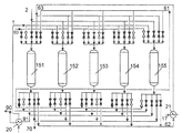
図8は、以下の段階を示す:第1の容量器(151)は、加圧モードおよび加熱モードに移行し、第2の容量器は再生されるべきであり、第3の容量器(153)はパージされるべきであり、第4の容量器(154)は冷却されるべきであり、第5の容量器(155)は精製されるべき水素のために作動中である。 FIG. 8 shows the following steps: the first capacitor (151) goes to the pressurization mode and the heating mode, the second capacitor is to be regenerated and the third capacitor (153) ) Should be purged, the fourth capacitor (154) should be cooled, and the fifth capacitor (155) is in operation for the hydrogen to be purified.
図9は、操作の第3の段階を示す:第1の容量器(151)は、水蒸気流通モードに変わり、第2の容量器(152)はパージされているところであり、第3の容量器(153)は冷却されているところであり、第4の容量器(154)は、水素精製モード中であり、第5の容量器(155)は、メタンによって加熱されているところである。 FIG. 9 shows the third stage of operation: the first capacitor (151) has changed to the steam flow mode and the second capacitor (152) has been purged, the third capacitor (153) is being cooled, the fourth capacitor (154) is in the hydrogen purification mode, and the fifth capacitor (155) is being heated by methane.
図10は、第4の操作段階を示す:第1の容量器(151)は、パージモードに移行し、第2の容量器(152)は冷却されているところであり、第3の容量器(153)は水素精製モード中であり、第4の容量器(154)はメタンによって加熱されているところであり、第5の容量器(155)は、水蒸気流通モードに移行する。 FIG. 10 shows the fourth operating phase: the first capacitor (151) has entered the purge mode, the second capacitor (152) is being cooled, and the third capacitor ( 153) is in the hydrogen purification mode, the fourth capacitor (154) is heated by methane, and the fifth capacitor (155) shifts to the steam flow mode.
図11は、第5の操作段階を示す:第1の容量器(151)は冷却されているところであり、第2の容量器(152)は水素精製モード中であり、第3の容量器(153)はメタンによって加熱されているところであり、第4の容量器(154)は水蒸気流通モードに移行し、第5の容量器(155)は、パージモードに移行する。 FIG. 11 shows a fifth operating phase: the first capacitor (151) is being cooled, the second capacitor (152) is in the hydrogen purification mode, and the third capacitor ( 153) is being heated by methane, the fourth capacitor (154) shifts to the steam flow mode, and the fifth capacitor (155) shifts to the purge mode.
サイクルは終わり、次の段階は、第1の段階と同様である。 The cycle is over and the next stage is similar to the first stage.
プロセスの間の操作条件および種々の流れの組成は、下記表1に、例えば3.3MPaでの水蒸気改質操作の場合において要約される。 The operating conditions during the process and the composition of the various streams are summarized in Table 1 below in the case of a steam reforming operation, for example at 3.3 MPa.
本発明の方法は、それ故に、(アミン洗浄を出る)水素リッチな流れの中に存在する不純物(CH4、CO、CO2)を捕捉し、かつ、それらを圧力下に水蒸気改質供給材料と共に戻すために用いられ得る。この方法は、以下のように要約され得る。 The process of the present invention therefore captures impurities (CH 4 , CO, CO 2 ) present in the hydrogen rich stream (exiting the amine wash) and causes them to be steam reformed under pressure. Can be used together with This method can be summarized as follows.
この方法(周期的である)は、複数の容量器を用い、連続する以下の工程を少なくとも含む:
・工程1:水素リッチな流れ中のメタン、COおよびCO2の吸着剤上への吸着。この工程は、20〜100℃の範囲、好ましくは40〜80℃の範囲、非常に好ましくは30〜70℃の範囲の低温で行われる。高純度の水素はこの工程を出る。吸着剤は、例えば、活性炭であり得る。一旦、吸着剤が飽和近くになると、容量器は、回路から分離され、別の容量器が作動状態にする;
・工程2:先行の工程において分離された容量器中の圧力は、次いで、増加させられ、それは、装置の終了時に圧力下に利用可能なプロセス供給原料(天然ガス)により加熱され、徐々に、水蒸気改質装置において約150℃に予備加熱される。天然ガスは、水蒸気との交換によって約300℃に加熱された後、吸着剤床に送られる。容量器中の熱天然ガスの移動は、吸着剤の床および壁を操作圧力における水蒸気凝結温度より少なくとも20℃高い温度に(3.5MPaにおいて255℃)再加熱し、これにより、次の工程の間の凝結のあらゆる危険性が回避される;
・工程3:再加熱された容量器のための吸着剤は、次いで、水蒸気改質入口において用いられた水蒸気を流通させることによって再生される。水蒸気は、不純物(主としてCH4)が吸着剤から脱着させられることを可能にし、それらを水蒸気改質反応器に送る。容量器を出る水蒸気は、交換器に送られ、予備加熱を目的として天然ガスを加熱させる;
・工程4:容量器は、次いで、分離され、次いで、容量器中に依然として存在する水蒸気を除くために高純度の熱水素を流される。熱水蒸気−飽和水素の一部は、次いで、水蒸気改質炉のためのバーナーに送られ、残りは、希釈水蒸気との混合物として、ガスタービンに送られる。現行のタービンは、高純度水素により機能し得ないが、当業者は、50%の水素および水蒸気の混合物によりそれが機能することを可能にするように少し適応させることができるだろう;
・工程5:容量器は、高純度の冷水素を流すことによって冷却される。容量器出口において加熱された水素は、希釈水蒸気との交換によってさらに加熱された後、工程4に送られる。
This method (which is periodic) uses a plurality of capacitors and includes at least the following successive steps:
- Step 1: Methane in the hydrogen-rich stream, adsorption onto the adsorbent of CO and CO 2. This step is performed at a low temperature in the range of 20-100 ° C, preferably in the range of 40-80 ° C, very preferably in the range of 30-70 ° C. High purity hydrogen exits this process. The adsorbent can be, for example, activated carbon. Once the adsorbent is near saturation, the capacitor is disconnected from the circuit and another capacitor is activated;
Step 2: The pressure in the capacitor separated in the previous step is then increased, which is heated by the process feed (natural gas) available under pressure at the end of the apparatus, and gradually Preheated to about 150 ° C. in a steam reformer. Natural gas is heated to about 300 ° C. by exchange with water vapor and then sent to the adsorbent bed. The transfer of hot natural gas in the capacitor reheats the bed and walls of the adsorbent to a temperature at least 20 ° C. above the water vapor condensation temperature at operating pressure (255 ° C. at 3.5 MPa), thereby allowing for the next step. Any risk of condensation in between is avoided;
Step 3: The adsorbent for the reheated capacitor is then regenerated by circulating the steam used at the steam reforming inlet. The steam allows impurities (mainly CH 4 ) to be desorbed from the adsorbent and sends them to the steam reforming reactor. The water vapor leaving the capacitor is sent to the exchanger to heat the natural gas for preheating purposes;
Step 4: The capacitor is then separated and then flushed with high purity hot hydrogen to remove the water vapor still present in the capacitor. A portion of the hot steam-saturated hydrogen is then sent to the burner for the steam reformer and the remainder is sent to the gas turbine as a mixture with diluted steam. Current turbines cannot function with high purity hydrogen, but those skilled in the art will be able to adapt a little to allow it to function with a mixture of 50% hydrogen and steam;
Step 5: The capacitor is cooled by flowing high purity cold hydrogen. The hydrogen heated at the outlet of the capacitor is further heated by exchange with diluted steam and then sent to step 4.
この方法は、プロセスの圧力がわずかにのみ変動する点で、従来技術において用いられるPSA(pressure swing adsorption)法から区別される(圧力変動の大きさは、水素製造ラインの全圧の降下にのみ対応する:例えば、圧力は、3.1と3.7MPaとの間で変わる、すなわち、たったの0.6MPaの圧力差)。脱着は、全圧を低減させることによって行われるのではなく、水蒸気を流すことによって行われ、これは、二重の効果:熱脱着およびCH4の分圧の低減を有する。 This method is distinguished from the pressure swing adsorption (PSA) method used in the prior art in that the process pressure fluctuates only slightly (the magnitude of the pressure fluctuation is only a drop in the total pressure of the hydrogen production line). Corresponding: for example, the pressure varies between 3.1 and 3.7 MPa, ie a pressure difference of only 0.6 MPa). Desorption is not performed by reducing the total pressure, but by flowing water vapor, which has a dual effect: thermal desorption and reduction of CH 4 partial pressure.
それ故に、本発明は、以下の利点を有する:
・それは、ほとんど全てのCO2を捕捉することができる;
・それは、圧縮器なしで、圧力下にメタンを水蒸気改質装置への入口に再循環させることができ、それ故に、エネルギーの喪失を伴わない;
・それは、上流のアミン洗浄装置において捕捉されるべきCO2の量に関する規制上の制約を緩めることができ、それ故に、関連したエネルギー消費量を低減させ得る。
The present invention therefore has the following advantages:
It can capture almost all CO 2 ;
It can recycle methane under pressure to the inlet to the steam reformer without a compressor and therefore without loss of energy;
It can relax regulatory restrictions on the amount of CO 2 to be captured in upstream amine scrubbers and therefore reduce the associated energy consumption.
以下の実施例は、本発明を例証する。 The following examples illustrate the invention.
(実施例1:本発明に合致する)
脱酸性化装置(MDEA)を出る水素リッチなガスの流れ(5300kmol/h)が、2.6MPaの圧力および57℃の温度で処理され、特にメタンが、これを水蒸気改質装置(SMR)に再循環させるために抽出された。
(Example 1: consistent with the present invention)
A hydrogen-rich gas stream (5300 kmol / h) exiting the deacidification unit (MDEA) is treated at a pressure of 2.6 MPa and a temperature of 57 ° C., especially methane, which is passed to the steam reformer (SMR). Extracted for recirculation.
このガスのモル組成は以下の通りである:
・H2: 92.9%
・CH4: 5.4%
・CO: 1.0%
・CO2: 0.1%
・H2O: 0.6%
それは、メタンの大部分をこのガスから捕捉することを目的としており、このガスは、約4600kg/hのマスフロー速度を示していた。
The molar composition of this gas is as follows:
・ H 2 : 92.9%
・ CH 4 : 5.4%
・ CO: 1.0%
・ CO 2 : 0.1%
・ H 2 O: 0.6%
It was intended to capture most of the methane from this gas, which showed a mass flow rate of about 4600 kg / h.
3.5mmの平均径を有する押出物状に成形された活性炭が用いられた。ミクロ孔容積(77Kでの窒素吸着によって測定される)は、0.505cm3/g、メソ孔容積は0.129cm3/gであり、マクロ孔容積(水銀ポロシメトリによって測定される)は、0.394cm3/gであった。そのBET比表面積は1263m2/gであった。 Activated carbon formed into an extrudate having an average diameter of 3.5 mm was used. The micropore volume (measured by nitrogen adsorption at 77 K) is 0.505 cm 3 / g, the mesopore volume is 0.129 cm 3 / g, and the macropore volume (measured by mercury porosimetry) is 0 394 cm 3 / g. The BET specific surface area was 1263m 2 / g.
この活性炭によるメタンの吸着容量は、57℃での0.143MPaの分圧について、1.1重量%であった。 The adsorption capacity of methane by this activated carbon was 1.1% by weight for a partial pressure of 0.143 MPa at 57 ° C.
メタンを除去するために、以下の特徴を有する吸着器が用いられた:内径3.9mおよび床全高14.2m。用いられた活性炭の量は70tであった。精製されるべき水素の表面速度は1.5m/分であった。吸着サイクル時間は10分であった。 To remove methane, an adsorber having the following characteristics was used: an inner diameter of 3.9 m and a total bed height of 14.2 m. The amount of activated carbon used was 70 t. The surface speed of the hydrogen to be purified was 1.5 m / min. The adsorption cycle time was 10 minutes.
吸着器の床は、以下の配列を用いて再生された:
・水蒸気改質装置のための供給材料として作用する天然ガスを用いた3分にわたる2.6MPaから3.5MPaへの吸着器の加圧;
・過熱水蒸気を用いた先行段階の向流脱着;入口温度は380℃であり、圧力は3.5MPaである。用いられた水蒸気の流量は50t/hであり、7分間にわたる、表面速度は4.3m/分であった;
・3分にわたる2.6MPaへの吸着器の脱圧;工程1の間に得られた精製水素を用いた、吸着器中に依然として存在する過熱水蒸気の排気、7t/hの流量であり、7分間にわたる。
The adsorber bed was regenerated using the following sequence:
Pressurization of the adsorber from 2.6 MPa to 3.5 MPa over 3 minutes with natural gas acting as feed for the steam reformer;
-Preliminary countercurrent desorption using superheated steam; inlet temperature is 380 ° C and pressure is 3.5 MPa. The water vapor flow rate used was 50 t / h and over 7 minutes, the surface speed was 4.3 m / min;
The depressurization of the adsorber to 2.6 MPa over 3 min; the exhaust of superheated steam still present in the adsorber using the purified hydrogen obtained during
これらの条件下に、メタンの95%は水素の流れから除去された。このメタンは、それ故に、圧縮器なしで水蒸気改質装置に直接的に再循環させられ得、それ故に、エネルギーの喪失を伴わなかった。メタンの再循環は、用いられる量の節約に寄与する。 Under these conditions, 95% of the methane was removed from the hydrogen stream. This methane could therefore be recycled directly to the steam reformer without a compressor and therefore was not accompanied by a loss of energy. Methane recirculation contributes to savings in the amount used.
(実施例2:本発明に合致する)
複合サイクル(ガスタービン+水蒸気の生成を伴うタービン出口における熱の回収および水蒸気タービン)を用いて400MWの電気が生じさせられるべきであった。
(Example 2: consistent with the present invention)
400 MW of electricity should have been generated using a combined cycle (gas turbine + heat recovery at the turbine outlet with steam generation and steam turbine).
天然ガスは、7MPaおよび40℃で提供され、以下のモル組成を有していた:
・CH4: 91%
・C2H6: 6%
・C3H8: 1%
・CO2: 2%
水蒸気改質、水蒸気転化および活性化MDEA吸着の後、生じたガスは、2.6MPa、57℃であり、以下のモル組成を有していた:
・H2: 92.9%
・CH4: 5.4%
・CO: 1%
・CO2: 0.1%
・H2O: 0.6%
それは、5℃過熱され、その結果、それは、もはや飽和しなくなり、吸着剤上の水のあらゆる凝結が回避された。
Natural gas was provided at 7 MPa and 40 ° C. and had the following molar composition:
・ CH 4 : 91%
・ C 2 H 6 : 6%
・ C 3 H 8 : 1%
・ CO 2 : 2%
After steam reforming, steam conversion and activated MDEA adsorption, the resulting gas was 2.6 MPa, 57 ° C. and had the following molar composition:
· H 2: 92.9%
・ CH 4 : 5.4%
・ CO: 1%
・ CO 2 : 0.1%
・ H 2 O: 0.6%
It was heated at 5 ° C. so that it was no longer saturated and any condensation of water on the adsorbent was avoided.
タービンに要求される高純度の水素の流量は、284700Nm3/hであった。 The flow rate of high purity hydrogen required for the turbine was 284700 Nm 3 / h.
水蒸気改質炉に要求される高純度の水素の流量は256350Nm3/hであった。 The flow rate of high-purity hydrogen required for the steam reforming furnace was 256350Nm 3 / h.
分離入口における水素の流量は、557280Nm3/hであった。 The flow rate of hydrogen at the separation inlet was 557280 Nm 3 / h.
天然ガスの流量は166387Nm3/hであった。 The flow rate of natural gas was 166387 Nm 3 / h.
水蒸気改質(3.6MPa,380℃)のための水蒸気の流量は476314Nm3/hであった。 The steam flow rate for steam reforming (3.6 MPa, 380 ° C.) was 476314 Nm 3 / h.
希釈水蒸気の流量は284700Nm3/hであった。 The flow rate of dilution water vapor was 284700Nm 3 / h.
工程1:
この工程の間、脱酸性装置(MDEA)を出る水素が、特にCH4の吸着によって精製された。
Step 1:
During this step, the hydrogen leaving the deacidifier (MDEA) was purified, in particular by adsorption of CH 4 .
圧力は、1〜10MPaの範囲、好ましくは2〜8MPaの範囲、非常に好ましくは1.5〜4MPaの範囲であり、温度は、20〜100℃の範囲、好ましくは40〜80℃の範囲であった。 The pressure is in the range of 1-10 MPa, preferably in the range of 2-8 MPa, very preferably in the range of 1.5-4 MPa, and the temperature is in the range of 20-100 ° C., preferably in the range of 40-80 ° C. there were.
ガスの流量は、0.5〜20m/分の範囲、好ましくは1〜10m/分の範囲であった。 The gas flow rate was in the range of 0.5-20 m / min, preferably in the range of 1-10 m / min.
吸着段階の期間は、1〜60分の範囲、好ましくは1〜30分の範囲、好ましくは1〜15分の範囲であった。 The duration of the adsorption stage was in the range of 1-60 minutes, preferably in the range of 1-30 minutes, preferably in the range of 1-15 minutes.
工程2:
この工程の間、吸着器、特に精製されるべき水素を含んでいるものは天然ガスを用いて加圧された。圧力変化は、精製されるべき水素の圧力と、利用可能であって過熱水蒸気の圧力との間の変化であった。
Step 2:
During this process, the adsorber, particularly one containing hydrogen to be purified, was pressurized with natural gas. The pressure change was a change between the pressure of the hydrogen to be purified and the pressure of the available superheated steam.
圧力は、0.05〜2MPa/分の範囲、好ましくは0.1〜1MPa/分の範囲、より好ましくは0.2〜0.5MPa/分の範囲の速さで増加させられた。 The pressure was increased at a rate in the range of 0.05-2 MPa / min, preferably in the range of 0.1-1 MPa / min, more preferably in the range of 0.2-0.5 MPa / min.
温度は、20〜400℃の範囲、好ましくは50〜300℃の範囲であった。 The temperature was in the range of 20-400 ° C, preferably in the range of 50-300 ° C.
工程3:
この工程の間、吸着された化合物の脱着が行われ、特に、CH4の脱着が過熱水蒸気を用いて行われた。
Step 3:
During this process, desorption of adsorbed compounds was performed, and in particular, CH 4 was desorbed using superheated steam.
圧力は、1〜10MPaの範囲、好ましくは2〜8MPaの範囲、非常に好ましくは1.5〜4MPaの範囲であり、温度は、20〜400℃の範囲、より好ましくは50〜300℃の範囲であった。 The pressure is in the range of 1-10 MPa, preferably in the range of 2-8 MPa, very preferably in the range of 1.5-4 MPa, and the temperature is in the range of 20-400 ° C., more preferably in the range of 50-300 ° C. Met.
ガス流量は、0.5〜20m/分の範囲、好ましくは1〜10m/分の範囲であった。 The gas flow rate was in the range of 0.5-20 m / min, preferably in the range of 1-10 m / min.
脱着段階の期間は、1〜180分の範囲、好ましくは1〜30分の範囲、より好ましくは1〜15分の範囲であった。 The duration of the desorption stage ranged from 1 to 180 minutes, preferably from 1 to 30 minutes, more preferably from 1 to 15 minutes.
脱着段階の期間は、吸着器出口における水蒸気の温度が考慮される圧力における水蒸気の露点より5℃超高くなるように選択され得る。この方法で開始することは、吸着剤のメソ細孔における水の凝結の危険性が大きく制限されることを意味する。 The duration of the desorption phase can be selected such that the temperature of the water vapor at the adsorber outlet is more than 5 ° C. above the dew point of the water vapor at the considered pressure. Starting with this method means that the risk of water condensation in the mesopores of the adsorbent is greatly limited.
工程4:
この工程の間、脱着工程3の終了時において吸着器中に依然として含まれる残留水蒸気のパージが行われた。
Step 4:
During this step, the residual water vapor still contained in the adsorber was purged at the end of the desorption step 3.
圧力は、1〜10MPaの範囲、好ましくは2〜8MPaの範囲であり、温度は、20〜400℃の範囲、好ましくは50〜300℃の範囲であった。 The pressure was in the range of 1-10 MPa, preferably in the range of 2-8 MPa, and the temperature was in the range of 20-400 ° C, preferably in the range of 50-300 ° C.
ガスの流量は、0.5〜20m/分の範囲、好ましくは1〜10m/分の範囲であった。 The gas flow rate was in the range of 0.5-20 m / min, preferably in the range of 1-10 m / min.
このパージ段階の継続期間は、1〜180分の範囲、好ましくは1〜30分の範囲、好ましくは1〜15分の範囲であった。 The duration of this purge phase was in the range of 1 to 180 minutes, preferably in the range of 1 to 30 minutes, preferably in the range of 1 to 15 minutes.
このパージ段階の継続期間は、吸着器に、例えば吸着器の1〜100容積の範囲、好ましくは吸着器の2〜50容積の範囲の容積のガスを流すように選択され得る。 The duration of this purge phase can be selected to flow gas in the adsorber, for example in a volume in the range of 1-100 volumes of the adsorber, preferably in the range of 2-50 volumes of the adsorber.
この工程において用いられるガスは、例えば、工程5または工程1の間に生じた精製水素の全部または一部であり得る。
The gas used in this step can be, for example, all or part of the purified hydrogen generated during step 5 or
工程5:
この工程の間に、工程4において残留過熱水蒸気を丁度パージされた吸着器が冷却された。
Step 5:
During this step, the adsorber just purged of residual superheated steam in step 4 was cooled.
圧力は、1〜10MPaの範囲、好ましくは2〜8MPaの範囲であり、温度は、20〜200℃の範囲、好ましくは50〜100℃の範囲であった。 The pressure was in the range of 1-10 MPa, preferably in the range of 2-8 MPa, and the temperature was in the range of 20-200 ° C, preferably in the range of 50-100 ° C.
ガスの流量は、0.5〜20m/分の範囲、好ましくは1〜10m/分の範囲であった。 The gas flow rate was in the range of 0.5-20 m / min, preferably in the range of 1-10 m / min.
吸着剤冷却段階の継続期間は、1〜180分の範囲、好ましくは1〜30分の範囲、より好ましくは1〜15分の範囲であった。 The duration of the adsorbent cooling phase was in the range of 1 to 180 minutes, preferably in the range of 1 to 30 minutes, more preferably in the range of 1 to 15 minutes.
この工程において用いられたガスは、例えば、工程1の間に生じた精製水素の全部または一部であり得る。
The gas used in this step can be, for example, all or part of the purified hydrogen generated during
吸着剤固体:
本発明によると、水素中に存在し、固体上に吸着された不純物の脱着工程は、過熱水蒸気を用いて行われる。吸着剤固体は、過熱水蒸気の存在下に高温、典型的には、室温から350℃の範囲の温度に抵抗することができなければならない。本発明によると、吸着剤は、活性炭または炭素モレキュラーシーブタイプの吸着剤から選択される。
Adsorbent solid:
According to the present invention, the process of desorbing impurities present in hydrogen and adsorbed on the solid is performed using superheated steam. The adsorbent solid must be able to resist high temperatures in the presence of superheated steam, typically in the range of room temperature to 350 ° C. According to the invention, the adsorbent is selected from activated carbon or carbon molecular sieve type adsorbents.
選択され得る活性炭群からの好適な例は、例えば酸を用いた化学活性化よりもむしろ水蒸気を用いた物理活性化によって調製された活性炭である。活性化条件は、特に、一般的には600〜900℃である温度に関して本発明の条件下に遭遇されたものよりシビアである。 Suitable examples from the group of activated carbons that can be selected are activated carbons prepared, for example, by physical activation using steam rather than chemical activation using acids. The activation conditions are more severe than those encountered under the conditions of the present invention, particularly for temperatures that are typically 600-900 ° C.
好ましくは、典型的には2nm未満の径を有するミクロ細孔および50nm超の径を有するマクロ細孔および最も低い可能性の量のメソ細孔(2〜50nmの範囲の径)を本質的に含有する活性炭が選択される。これらの径は、例えば、当業者に周知であるBJH法(メソ細孔領域)を用いた77Kにおける窒素吸着等温線およびWashburnの法則を用いた水銀圧入曲線(メソ細孔領域)(これも当業者に周知である)を用いて計算され得る。 Preferably, micropores typically having a diameter of less than 2 nm and macropores having a diameter greater than 50 nm and the lowest possible amount of mesopores (diameters in the range of 2-50 nm) are essentially The activated carbon contained is selected. These diameters are, for example, the nitrogen adsorption isotherm at 77K using the BJH method (mesopore region) well known to those skilled in the art and the mercury intrusion curve (mesopore region) using Washburn's law. Well known to the vendor).
このような選択についての理由は、吸着剤の床中に存在する水蒸気は特に工程3および4において結果として活性炭のメソ細孔における毛管凝縮の現象(特に、過熱水の温度が考慮される圧力における露点に実質的に落ちる場合)をもたらし得るという事実によって説明される。メソ細孔においてこの毛管凝縮現象を生じさせ得る水蒸気の相対的な圧力は、水に関するパラメータを用いたケルビンの式を用いて計算され得る。この点における参照は、例えば、S. J. GreggおよびK. S. W. Singによる著書(Adsorption, Surface Area and Porosity)およびJ. Rouquerolらによる著書(Adsorption by Powders and Porous Solids)に対してなされるべきである。 The reason for this choice is that the water vapor present in the bed of adsorbent is a phenomenon of capillary condensation particularly in the mesopores of the activated carbon resulting in steps 3 and 4 (especially at pressures where the temperature of superheated water is taken into account) Explained by the fact that it can result in a substantial drop in the dew point. The relative pressure of water vapor that can cause this capillary condensation phenomenon in the mesopores can be calculated using the Kelvin equation with parameters relating to water. Reference in this respect should be made, for example, to books by S. J. Gregg and K. S. W. Sing (Adsorption, Surface Area and Porosity) and by J. Rouquerol et al. (Adsorption by Powders and Porous Solids).
本発明の関連において用いられた活性炭は、例えば0.5〜5nmの径を有する顆粒状または約0.5〜数mmの長さを有する押出物状、または数ミリメートルの特徴的寸法を有する粉砕材料状に成形される。 The activated carbon used in the context of the present invention is, for example, granular with a diameter of 0.5 to 5 nm or extrudate with a length of about 0.5 to several mm, or ground with a characteristic dimension of a few millimeters. Molded into a material.
活性炭のミクロ孔容積は、例えば0.05〜0.80cm3/gの範囲である(これは、例えばt-plot法またはDubinin式またはその変形を用いた77Kでの窒素吸着によって測定される)。 The micropore volume of the activated carbon is, for example, in the range of 0.05 to 0.80 cm 3 / g (this is measured, for example, by nitrogen adsorption at 77 K using the t-plot method or Dubinin equation or variants thereof). .
メソ孔容積は、好ましくは0.05〜0.30cm3/gの範囲である(これは、ミクロ孔容積に低減させられた0.98〜0.99に近い相対圧力P/P0における77Kでの窒素吸着によって測定される)。 The mesopore volume is preferably in the range of 0.05-0.30 cm 3 / g (this is 77 K at a relative pressure P / P 0 close to 0.98-0.99 reduced to a micropore volume. Measured by nitrogen adsorption).
マクロ孔容積は、好ましくは0.10〜0.50cm3/gの範囲である(これは、水銀圧入によって測定される)。 Macropore volume preferably in the range of 0.10~0.50cm 3 / g (which is measured by mercury intrusion).
挙げられ得るこの基準を満足する活性炭の例は、Ceca/Arkemaからの活性炭AC35/3、およびPica Carbonからの活性炭PicaCarb E460-EおよびPicactif TA60またはTA90である。 Examples of activated carbons that meet this criteria that may be mentioned are activated carbon AC35 / 3 from Ceca / Arkema and activated carbon PicaCarb E460-E and Picactif TA60 or TA90 from Pica Carbon.
この例では、CO2放出を伴わないでかつメタンの再循環を伴って400MWの電気が生じさせられた。 In this example, 400 MW of electricity was caused with a and recycle of methane is without CO 2 release.
本発明は上記に与えられた詳述に制限されてはならないことが当業者に明らかであるべきであり、本発明の適用領域を逸脱することなく多くの他の具体的な形態の実施を許容する。結果として、本発明の実施は、例示の目的であると考えられるべきであり、添付の特許請求の範囲によって規定された範囲を決して逸脱することなく改変され得る。 It should be apparent to those skilled in the art that the present invention should not be limited to the details provided above, and many other specific embodiments may be implemented without departing from the scope of the present invention. To do. As a result, the practice of the present invention should be considered as illustrative and can be modified without departing from the scope defined by the appended claims.
1 ライン
2 ライン
10 ライン
11 水蒸気改質装置
12 水蒸気転化装置
13 CO2捕捉装置
15 活性炭吸着装置
16 ガスタービン
17 ライン
30 ライン
40 ライン
50 ライン
60 ライン
70 ライン
80 ライン
90 ライン
110 炉出口
1
Claims (14)
・水蒸気の存在下に炭化水素供給材料を水蒸気改質するための装置において合成ガスを製造する工程であって、燃料が反応に必要な熱を提供する、工程と、
・先行工程において得られた合成ガスを水蒸気転化し、メタンおよび二酸化炭素を含有する水素の流れを生じさせる工程と、
・該水蒸気転化工程から得られた流れ中に存在する二酸化炭素を捕捉し、水素の流れから二酸化炭素を分離する工程と、
・水素の流れの中に存在する不純物を捕捉し、これを該水蒸気改質工程に再循環させる工程と
を包含する方法 A process for producing hydrogen from a hydrocarbon feedstock and steam comprising:
A process for producing synthesis gas in an apparatus for steam reforming a hydrocarbon feed in the presence of steam, wherein the fuel provides the heat necessary for the reaction;
A step of steam-converting the synthesis gas obtained in the preceding step to produce a flow of hydrogen containing methane and carbon dioxide;
Capturing carbon dioxide present in the stream obtained from the steam conversion step and separating the carbon dioxide from the hydrogen stream;
Trapping impurities present in the hydrogen stream and recycling them to the steam reforming step
・第1の吸着器上に不純物を吸着させる段階と、
・第1の吸着器を再生し、第2の吸着器上に不純物を吸着させる段階と
の連続段階の少なくとも1つを包含する、請求項1または2に記載の水素製造方法。 The impurity trapping / recycling step is performed in an adsorption device including at least two adsorbers,
Adsorbing impurities on the first adsorber;
The method for producing hydrogen according to claim 1 or 2, comprising at least one of a continuous step of regenerating the first adsorber and adsorbing impurities onto the second adsorber.
・飽和した時に吸着器を分離し、第2の吸着器を作動状態にすること;
・第1の吸着器に、炭化水素供給材料であって、水蒸気改質装置のための供給材料として作用させることを目的とし、同様に水蒸気改質装置を目的とした水蒸気との交換によって、水蒸気の凝結温度より少なくとも20℃高い温度に加熱された炭化水素供給材料の流れを流すこと;
・水蒸気改質装置を目的として少なくとも20℃過熱された水蒸気を流通させることによって、加熱された吸着器を再生し、不純物を脱着させること;
・吸着器に、高純度の熱水素の流れを流すことによって再生された吸着器中に存在する水蒸気を除去すること
・水蒸気を含有しない吸着器に、高純度の冷水素の流れを流すこと
により行われる、請求項3に記載の水素製造方法。 The adsorber regeneration stage
Separating the adsorber when saturated and bringing the second adsorber into operation;
The first adsorber is a hydrocarbon feed material, intended to act as a feed material for a steam reformer, and by replacing it with steam for the same purpose as a steam reformer Flowing a stream of hydrocarbon feed heated to a temperature at least 20 ° C. above the condensation temperature of
Regenerating the heated adsorber and desorbing impurities by circulating steam that has been heated at least 20 ° C. for the purpose of a steam reformer;
・ Removing water vapor present in the resorbed adsorber by flowing high purity hot hydrogen flow through the adsorber ・ By flowing high purity cold hydrogen flow through the adsorber that does not contain water vapor The hydrogen production method according to claim 3, which is performed.
Applications Claiming Priority (2)
| Application Number | Priority Date | Filing Date | Title |
|---|---|---|---|
| FR0805390A FR2936507B1 (en) | 2008-09-29 | 2008-09-29 | PROCESS FOR THE PRODUCTION OF HYDROGEN WITH TOTAL CO2 CAPTATION AND RECYCLING OF NON-CONVERTED METHANE |
| FR0805390 | 2008-09-29 |
Publications (3)
| Publication Number | Publication Date |
|---|---|
| JP2010083754A true JP2010083754A (en) | 2010-04-15 |
| JP2010083754A5 JP2010083754A5 (en) | 2012-11-15 |
| JP5542397B2 JP5542397B2 (en) | 2014-07-09 |
Family
ID=40512588
Family Applications (1)
| Application Number | Title | Priority Date | Filing Date |
|---|---|---|---|
| JP2009224062A Expired - Fee Related JP5542397B2 (en) | 2008-09-29 | 2009-09-29 | Process for producing hydrogen with complete capture of CO2 and recycling unconverted methane |
Country Status (6)
| Country | Link |
|---|---|
| US (1) | US8790617B2 (en) |
| EP (1) | EP2168913B1 (en) |
| JP (1) | JP5542397B2 (en) |
| CA (1) | CA2679771C (en) |
| FR (1) | FR2936507B1 (en) |
| RU (1) | RU2509720C2 (en) |
Cited By (5)
| Publication number | Priority date | Publication date | Assignee | Title |
|---|---|---|---|---|
| WO2011122361A1 (en) | 2010-03-31 | 2011-10-06 | Hitachi Koki Co., Ltd. | Power tool |
| JP2012025655A (en) * | 2010-07-23 | 2012-02-09 | IFP Energies Nouvelles | Process for producing hydrogen with intermediate-pressure purging |
| JP2013230105A (en) * | 2012-04-27 | 2013-11-14 | Ito En Ltd | Method of producing tea beverage |
| JP2020089815A (en) * | 2018-12-03 | 2020-06-11 | 古河電気工業株式会社 | Manufacturing device of synthetic gas and manufacturing method of synthetic gas |
| KR20220070791A (en) * | 2020-11-23 | 2022-05-31 | 노용규 | Hydrocarbon pyrolysis apparatus and operation method thereof |
Families Citing this family (8)
| Publication number | Priority date | Publication date | Assignee | Title |
|---|---|---|---|---|
| US8137422B2 (en) * | 2009-06-03 | 2012-03-20 | Air Products And Chemicals, Inc. | Steam-hydrocarbon reforming with reduced carbon dioxide emissions |
| FR2949772A1 (en) * | 2009-09-04 | 2011-03-11 | Total Raffinage Marketing | Producing a synthesis gas containing hydrogen from a hydrocarbon charge including e.g. methane or naphtha, comprises transforming hydrocarbon charge into synthesis gas in vapor-reforming furnace, and treating the synthesis gas |
| US20140047978A1 (en) * | 2011-03-31 | 2014-02-20 | Uop Llc | Process for purifying a gas in a temperature swing adsorption unit |
| RU2485330C1 (en) * | 2011-11-16 | 2013-06-20 | Федеральное государственное бюджетное учреждение "Национальный исследовательский центр "Курчатовский институт" | Method of energy generation |
| US9023244B2 (en) | 2012-12-31 | 2015-05-05 | Chevron U.S.A. Inc. | Capture of CO2 from hydrogen plants |
| CN108253729B (en) * | 2018-03-09 | 2023-09-19 | 杭州中泰深冷技术股份有限公司 | System for cryogenic separation co-production of methane gas from coal chemical synthesis gas and process method thereof |
| RU2729790C1 (en) * | 2020-02-28 | 2020-08-12 | Игорь Анатольевич Мнушкин | Gas chemical production of hydrogen |
| EP4244182A1 (en) | 2020-11-13 | 2023-09-20 | Technip Energies France | A process for producing a hydrogen-comprising product gas from a hydrocarbon |
Citations (7)
| Publication number | Priority date | Publication date | Assignee | Title |
|---|---|---|---|---|
| JPS6197124A (en) * | 1984-10-18 | 1986-05-15 | インペリアル・ケミカル・インダストリーズ・ピーエルシー | Collection of carbon dioxide |
| JPS61197403A (en) * | 1985-02-27 | 1986-09-01 | Jgc Corp | Production of hydrogen |
| JPS6241701A (en) * | 1985-08-13 | 1987-02-23 | Mitsubishi Heavy Ind Ltd | Pressure swing type gas separator in methanol decomposition apparatus |
| JPS62500572A (en) * | 1983-05-13 | 1987-03-12 | ユニオン カ−バイド コ−ポレ−シヨン | Method for producing activated carbon adsorbent pellets with high heat capacity and pelletized activated carbon adsorbent with high heat capacity |
| JP2003104720A (en) * | 2001-09-28 | 2003-04-09 | Kanebo Ltd | Molecular sieve carbon and pressure swing adsorption apparatus using it |
| JP2004299996A (en) * | 2003-03-31 | 2004-10-28 | Osaka Gas Co Ltd | Operation method for hydrogen production apparatus |
| JP2007500115A (en) * | 2003-07-28 | 2007-01-11 | ウーデ・ゲゼルシャフト・ミト・ベシュレンクテル・ハフツング | Process for producing hydrogen from methane-containing gas, in particular natural gas, and system for carrying out the process |
Family Cites Families (13)
| Publication number | Priority date | Publication date | Assignee | Title |
|---|---|---|---|---|
| FR2557555B1 (en) * | 1983-12-30 | 1987-05-15 | Inst Francais Du Petrole | NOVEL PROCESS FOR THE MANUFACTURE OF SYNTHETIC GAS FOR USE IN PARTICULAR FOR THE PRODUCTION OF METHANOL |
| DE3571797D1 (en) * | 1984-03-02 | 1989-08-31 | Ici Plc | Process for producing ammonia synthesis gas |
| RU1819848C (en) * | 1990-11-22 | 1993-06-07 | Грозненский нефтяной научно-исследовательский институт | Method for thermocatalytic production of hydrogen |
| US5430303A (en) * | 1992-07-01 | 1995-07-04 | Nikon Corporation | Exposure apparatus |
| US5669960A (en) * | 1995-11-02 | 1997-09-23 | Praxair Technology, Inc. | Hydrogen generation process |
| DK1152815T3 (en) * | 1998-11-23 | 2009-06-08 | Fluor Corp | Stream splitting process and apparatus |
| US6521143B1 (en) * | 2000-04-13 | 2003-02-18 | Air Products And Chemicals, Inc. | Co-production of carbon monoxide-rich syngas wth high purity hydrogen |
| US6706770B2 (en) * | 2002-04-04 | 2004-03-16 | Air Products And Chemicals, Inc. | Co-production of hydrogen and methanol from steam reformate |
| US7708809B2 (en) * | 2002-11-20 | 2010-05-04 | Mitsubishi Materials Corporation | Hydrogen permeable membrane |
| RU2271333C2 (en) * | 2004-03-25 | 2006-03-10 | Институт Катализа Им. Г.К. Борескова Сибирского Отделения Российской Академии Наук | Hydrogen-containing gas generation process |
| US7752848B2 (en) * | 2004-03-29 | 2010-07-13 | General Electric Company | System and method for co-production of hydrogen and electrical energy |
| US7399341B2 (en) * | 2005-04-26 | 2008-07-15 | Uop Llc | Gas purification process |
| FR2910457B1 (en) * | 2006-12-22 | 2009-03-06 | Inst Francais Du Petrole | PROCESS FOR HYDROGEN ADSORPTION PURIFICATION WITH COGENERATION OF A PRESSURE CO2 FLOW |
-
2008
- 2008-09-29 FR FR0805390A patent/FR2936507B1/en not_active Expired - Fee Related
-
2009
- 2009-09-11 EP EP09290691.6A patent/EP2168913B1/en not_active Not-in-force
- 2009-09-25 CA CA2679771A patent/CA2679771C/en not_active Expired - Fee Related
- 2009-09-28 RU RU2009136005/05A patent/RU2509720C2/en not_active IP Right Cessation
- 2009-09-28 US US12/568,317 patent/US8790617B2/en not_active Expired - Fee Related
- 2009-09-29 JP JP2009224062A patent/JP5542397B2/en not_active Expired - Fee Related
Patent Citations (7)
| Publication number | Priority date | Publication date | Assignee | Title |
|---|---|---|---|---|
| JPS62500572A (en) * | 1983-05-13 | 1987-03-12 | ユニオン カ−バイド コ−ポレ−シヨン | Method for producing activated carbon adsorbent pellets with high heat capacity and pelletized activated carbon adsorbent with high heat capacity |
| JPS6197124A (en) * | 1984-10-18 | 1986-05-15 | インペリアル・ケミカル・インダストリーズ・ピーエルシー | Collection of carbon dioxide |
| JPS61197403A (en) * | 1985-02-27 | 1986-09-01 | Jgc Corp | Production of hydrogen |
| JPS6241701A (en) * | 1985-08-13 | 1987-02-23 | Mitsubishi Heavy Ind Ltd | Pressure swing type gas separator in methanol decomposition apparatus |
| JP2003104720A (en) * | 2001-09-28 | 2003-04-09 | Kanebo Ltd | Molecular sieve carbon and pressure swing adsorption apparatus using it |
| JP2004299996A (en) * | 2003-03-31 | 2004-10-28 | Osaka Gas Co Ltd | Operation method for hydrogen production apparatus |
| JP2007500115A (en) * | 2003-07-28 | 2007-01-11 | ウーデ・ゲゼルシャフト・ミト・ベシュレンクテル・ハフツング | Process for producing hydrogen from methane-containing gas, in particular natural gas, and system for carrying out the process |
Cited By (7)
| Publication number | Priority date | Publication date | Assignee | Title |
|---|---|---|---|---|
| WO2011122361A1 (en) | 2010-03-31 | 2011-10-06 | Hitachi Koki Co., Ltd. | Power tool |
| JP2012025655A (en) * | 2010-07-23 | 2012-02-09 | IFP Energies Nouvelles | Process for producing hydrogen with intermediate-pressure purging |
| JP2013230105A (en) * | 2012-04-27 | 2013-11-14 | Ito En Ltd | Method of producing tea beverage |
| JP2020089815A (en) * | 2018-12-03 | 2020-06-11 | 古河電気工業株式会社 | Manufacturing device of synthetic gas and manufacturing method of synthetic gas |
| JP7327929B2 (en) | 2018-12-03 | 2023-08-16 | 古河電気工業株式会社 | Syngas production apparatus and synthesis gas production method |
| KR20220070791A (en) * | 2020-11-23 | 2022-05-31 | 노용규 | Hydrocarbon pyrolysis apparatus and operation method thereof |
| KR102482738B1 (en) * | 2020-11-23 | 2022-12-28 | 노용규 | Hydrocarbon pyrolysis apparatus and operation method thereof |
Also Published As
| Publication number | Publication date |
|---|---|
| CA2679771C (en) | 2017-03-21 |
| CA2679771A1 (en) | 2010-03-29 |
| JP5542397B2 (en) | 2014-07-09 |
| EP2168913B1 (en) | 2018-11-14 |
| FR2936507B1 (en) | 2011-04-08 |
| US20100080754A1 (en) | 2010-04-01 |
| FR2936507A1 (en) | 2010-04-02 |
| US8790617B2 (en) | 2014-07-29 |
| RU2009136005A (en) | 2011-04-10 |
| RU2509720C2 (en) | 2014-03-20 |
| EP2168913A1 (en) | 2010-03-31 |
Similar Documents
| Publication | Publication Date | Title |
|---|---|---|
| JP5542397B2 (en) | Process for producing hydrogen with complete capture of CO2 and recycling unconverted methane | |
| US8268044B2 (en) | Separation of a sour syngas stream | |
| CA2732129C (en) | Recovery of carbon dioxide from flue gas | |
| CA2745359C (en) | A method and apparatus for producing power and hydrogen | |
| CA2046772C (en) | Carbon dioxide production from combustion exhaust gases with nitrogen and argon by-product recovery | |
| US8926941B2 (en) | Capture of CO2 from hydrogen plants using a temperature swing adsorption method | |
| JP2010083754A5 (en) | ||
| CA2782162A1 (en) | Method for the production of hydrogen combined with carbon dioxide capture | |
| NO854134L (en) | GAS PRODUCTION. | |
| JP5748272B2 (en) | Helium gas purification method and purification apparatus | |
| JP5840884B2 (en) | Method for producing hydrogen by purging at intermediate pressure | |
| JPS6248793A (en) | Production of hydrogen-containing gas stream | |
| JPS6230603A (en) | Manufacture of industrial hydrogen | |
| CA3192314A1 (en) | Sorption-enhanced water-gas shift process for the formation of a co2 product stream and an h2 product stream |
Legal Events
| Date | Code | Title | Description |
|---|---|---|---|
| A521 | Written amendment |
Free format text: JAPANESE INTERMEDIATE CODE: A523 Effective date: 20120928 |
|
| A621 | Written request for application examination |
Free format text: JAPANESE INTERMEDIATE CODE: A621 Effective date: 20120928 |
|
| A977 | Report on retrieval |
Free format text: JAPANESE INTERMEDIATE CODE: A971007 Effective date: 20131018 |
|
| A131 | Notification of reasons for refusal |
Free format text: JAPANESE INTERMEDIATE CODE: A131 Effective date: 20131029 |
|
| A521 | Written amendment |
Free format text: JAPANESE INTERMEDIATE CODE: A523 Effective date: 20140121 |
|
| TRDD | Decision of grant or rejection written | ||
| A01 | Written decision to grant a patent or to grant a registration (utility model) |
Free format text: JAPANESE INTERMEDIATE CODE: A01 Effective date: 20140408 |
|
| A61 | First payment of annual fees (during grant procedure) |
Free format text: JAPANESE INTERMEDIATE CODE: A61 Effective date: 20140507 |
|
| R150 | Certificate of patent or registration of utility model |
Ref document number: 5542397 Country of ref document: JP Free format text: JAPANESE INTERMEDIATE CODE: R150 |
|
| R250 | Receipt of annual fees |
Free format text: JAPANESE INTERMEDIATE CODE: R250 |
|
| R250 | Receipt of annual fees |
Free format text: JAPANESE INTERMEDIATE CODE: R250 |
|
| LAPS | Cancellation because of no payment of annual fees |