JP2010081853A - Transplantation machine for continuous pot seedling - Google Patents

Transplantation machine for continuous pot seedling Download PDF

Info

Publication number
JP2010081853A
JP2010081853A JP2008253675A JP2008253675A JP2010081853A JP 2010081853 A JP2010081853 A JP 2010081853A JP 2008253675 A JP2008253675 A JP 2008253675A JP 2008253675 A JP2008253675 A JP 2008253675A JP 2010081853 A JP2010081853 A JP 2010081853A
Authority
JP
Japan
Prior art keywords
potted seedling
potted
continuous
seedling
seedlings
Prior art date
Legal status (The legal status is an assumption and is not a legal conclusion. Google has not performed a legal analysis and makes no representation as to the accuracy of the status listed.)
Granted
Application number
JP2008253675A
Other languages
Japanese (ja)
Other versions
JP5215801B2 (en
Inventor
Yasunobu Kawamoto
靖信 川本
Hiroyuki Sakai
啓之 坂井
Current Assignee (The listed assignees may be inaccurate. Google has not performed a legal analysis and makes no representation or warranty as to the accuracy of the list.)
Nippon Beet Sugar Manufacturing Co Ltd
Original Assignee
Nippon Beet Sugar Manufacturing Co Ltd
Priority date (The priority date is an assumption and is not a legal conclusion. Google has not performed a legal analysis and makes no representation as to the accuracy of the date listed.)
Filing date
Publication date
Application filed by Nippon Beet Sugar Manufacturing Co Ltd filed Critical Nippon Beet Sugar Manufacturing Co Ltd
Priority to JP2008253675A priority Critical patent/JP5215801B2/en
Publication of JP2010081853A publication Critical patent/JP2010081853A/en
Application granted granted Critical
Publication of JP5215801B2 publication Critical patent/JP5215801B2/en
Active legal-status Critical Current
Anticipated expiration legal-status Critical

Links

Images

Landscapes

  • Transplanting Machines (AREA)

Abstract

<P>PROBLEM TO BE SOLVED: To provide a transplantation machine for continuous pot seedlings capable of transplanting continuous pot seedlings in one planting groove in multiple rows and to provide a transplantation method for continuous pot seedlings. <P>SOLUTION: Two pot seedling trays 9a, 9b are placed on a pot seedling table 5 in a state aligned in lateral direction of the machine, individual continuous pot seedlings 6a, 6b drawn from corresponding pot seedling trays 9a, 9b are collected and aligned by a pot seedling guide 7, and the aligned continuous pot seedlings 6a, 6b are delivered from a pot seedling delivery part 8 and planted on one planting groove. <P>COPYRIGHT: (C)2010,JPO&INPIT

Description

本発明は、連続鉢苗をその集合体から引き出して整列させて圃場に移植する連続鉢苗移植機および連続鉢苗移植方法の改良に関する。   The present invention relates to an improvement of a continuous potted seedling transplanting machine and a continuous potted seedling transplanting method for pulling out continuous potted seedlings from the aggregate, aligning them and transplanting them in a field.

従来、進行方向後側の下面を接地面とした機台上に、その進行方向前側から順次、連続鉢苗を載置する鉢苗載置部と、該鉢苗載置部から引き出した連続鉢苗を1列に整列させて案内する鉢苗案内部と、該鉢苗案内部から植付け面に連続鉢苗を繰り出す鉢苗繰出し部と、を設け、さらに、圃場に植付け溝を形成する溝切部を機台の接地面に設けると共に該機台の進行方向前端部にハンドルを備える連続鉢苗移植機が知られている(例えば、特許文献1参照)。この連続鉢苗移植機では、作業者がハンドルを牽いて当該移植機を前進させると、溝切部により圃場の植付け面に1条の植付け溝が形成され、該植付け溝に、鉢苗載置部から引き出されて鉢苗案内部により1列に整列させた連続鉢苗が、鉢苗繰出し部から繰り出されて移植される。   Conventionally, a potted seedling placement unit for placing continuous potted seedlings sequentially from the front side of the traveling direction on a machine base having a lower surface on the rear side in the traveling direction as a ground contact surface, and a continuous pot drawn from the potted seedling placement unit Groove cutting which provides a potted seedling guide part for aligning and guiding seedlings in a row and a potted seedling feeding part for feeding continuous potted seedlings from the potted seedling guide part to the planting surface, and further forming a planting groove in the field There is known a continuous potted seedling transplanting machine in which a portion is provided on the grounding surface of a machine base and a handle is provided at the front end in the traveling direction of the machine base (for example, see Patent Document 1). In this continuous potted seedling transplanting machine, when the operator checks the handle and advances the transplanting machine, a single groove is formed on the planting surface of the field by the groove cutting part, and the potted seedling placement is placed in the planting groove. The continuous potted seedlings drawn out from the section and aligned in a row by the potted seedling guiding section are drawn out from the potted seedling feeding section and transplanted.

ところで、長ネギは、苗を比較的大きく成長させてから圃場に移植する作型(春撒き栽培)が知られている。この作型に上述した連続鉢苗を適用する場合、1つの鉢体に1粒で播種することが好ましい。1つの鉢体に1粒で播種する場合、苗を大きく(太く)成長させる点で有利であるが、畦に移植される苗の数が少なく採算が合わないことから、連続鉢苗移植機を使用して移植することができず、移植は手作業により行われていたが、作業に多大な時間を要するのに加え、作業者への負担も大きかった。しかしながら、1つの鉢体に複数粒を播種した場合、苗が大きく育たず商品価値が低下してしまう。そこで、2つの連続鉢苗集合体を鉢苗載置部に並置し、各集合体から引き出された各連続鉢苗を合一させて1列にすることで、畦に形成した1条の植付け溝に連続鉢苗を複数列で移植することが試みられたが、苗が倒れてしまったり連続鉢苗が絡んでしまう不具合を生じることから実用化が困難であった。
特開平8−89028号公報
By the way, the long leek is known to have a cropping type (spring-grown cultivation) in which seedlings are grown relatively large and then transplanted to a field. When applying the above-mentioned continuous potted seedling to this mold, it is preferable to sow one pot in one pot. When sowing one pot in one pot, it is advantageous in that the seedlings grow large (thick), but since the number of seedlings transplanted into the cocoon is small and not profitable, a continuous potted seedling transplanter is used. It was impossible to use and transplant, and the transplantation was performed manually. However, in addition to the time required for the operation, the burden on the operator was great. However, when a plurality of grains are sown in one pot body, the seedling does not grow greatly and the commercial value is lowered. Therefore, two continuous potted seedling aggregates are juxtaposed on the potted seedling placement part, and the continuous potted seedlings drawn from each aggregate are combined into one row, so that one row of plants formed on the cocoon Attempts were made to transplant continuous potted seedlings in multiple rows in the groove, but it was difficult to put to practical use because the seedlings would fall or the continuous potted seedlings would get involved.
JP-A-8-89028

そこで本発明は、上記事情に鑑みてなされたもので、1条の植付け溝に連続鉢苗を複数列で移植することが可能な連続鉢苗移植機および連続鉢苗移植方法を提供することを課題としてなされたものである。   Then, this invention was made | formed in view of the said situation, and provides the continuous potted seedling transplanting machine and the continuous potted seedling transplanting method which can transplant a continuous potted seedling in multiple rows in one planting groove | channel. It was made as an issue.

上記課題を解決するために、本発明のうち請求項1に記載の発明は、進行方向後側の下面を接地面とした機台上に、その進行方向前側から順次、連続鉢苗を載置する鉢苗載置部と、該鉢苗載置部から引き出された前記連続鉢苗を1列に整列させて案内する鉢苗案内部と、該鉢苗案内部から植付け面へ前記連続鉢苗を繰り出す鉢苗繰出し部と、が設けられ、さらに、前記機台の接地面に、圃場に植付け溝を形成する溝切部が設けられる連続鉢苗移植機であって、前記鉢苗載置部が機台幅方向へ並ぶ複数の鉢苗載置領域に区画され、さらに、前記鉢苗案内部に設けられ、各鉢苗載置領域から引き出された各連続鉢苗を集約しつつ整列させる鉢苗整列手段を有することを特徴とする。
請求項2に記載の発明は、請求項1に記載の連続鉢苗移植機において、さらに、前記鉢苗案内部から前記鉢苗繰出し部まで延び、前記鉢苗整列手段により整列させた前記連続鉢苗の隣り合う前記連続鉢苗間を仕切る仕切手段を有することを特徴とする。
請求項3に記載の発明は、請求項1または2に記載の連続鉢苗移植機において、前記鉢苗整列手段は、集約された前記連続鉢苗の通過を許容する間隔をあけて対向配置される1対の鉢苗整列部材を有することを特徴とする。
請求項4に記載の発明は、請求項1−3のいずれかに記載の連続鉢苗移植機において、前記鉢苗整列手段の各鉢苗整列部材は、前記連続鉢苗の姿勢を矯正する姿勢矯正部と、姿勢が矯正された前記連続鉢苗を整列させて前記鉢苗繰出し部へ向けて案内する案内部と、を有することを特徴とする。
請求項5に記載の発明は、請求項1−4のいずれかに記載の連続鉢苗移植機において、さらに、前記1対の鉢苗整列部材が前記鉢苗繰出し部に設けられることを特徴とする。
上記課題を解決するために、本発明のうち請求項6に記載の発明は、連続鉢苗移植機を移動させて該移植機の溝切部により圃場に植付け溝を形成しつつ鉢苗載置部から引き出された連続鉢苗を前記植付け溝へ繰り出して移植する方法であって、前記鉢苗載置部を機台幅方向へ並ぶ複数の鉢苗載置領域に区画しておいて、各鉢苗載置領域から引き出された各連続鉢苗を集約しつつ整列させ、該整列させた各連続鉢苗を前記植付け溝へ繰出して移植することを特徴とする。
請求項7に記載の発明は、請求項6に記載の連続鉢苗移植方法において、整列させた前記連続鉢苗の隣り合う前記連続鉢苗間を仕切板により仕切りつつ、各連続鉢苗を前記植付け溝へ繰出して移植することを特徴とする。
In order to solve the above-mentioned problems, the invention according to claim 1 of the present invention is such that continuous potted seedlings are placed in order from the front side in the traveling direction on the machine base having the lower surface on the rear side in the traveling direction as the ground surface. A potted seedling placement part, a potted seedling guide part that guides the continuous potted seedling drawn from the potted seedling placement part in a row, and the continuous potted seedling from the potted seedling guide part to the planting surface A continuous potted seedling transplanting machine provided with a groove cutting part for forming a planting groove in a field on the grounding surface of the machine stand, wherein the potted seedling placing part is provided. Is divided into a plurality of potted seedling placement areas arranged in the machine width direction, and is further provided in the potted seedling guide unit, and the continuous potted seedlings drawn from the potted seedling placement areas are aggregated and aligned. It has a seedling alignment means.
The invention according to claim 2 is the continuous potted seedling transplanting machine according to claim 1, further extending from the potted seedling guide part to the potted seedling feeding part and aligned by the potted seedling arranging means. It has a partition means for partitioning the continuous potted seedlings adjacent to each other.
According to a third aspect of the present invention, in the continuous potted seedling transplanting machine according to the first or second aspect, the potted seedling arranging means are arranged to face each other with an interval that allows passage of the aggregated continuous potted seedlings. And a pair of potted seedling alignment members.
Invention of Claim 4 is the attitude | position which corrects the attitude | position of the said continuous potted seedling in each potted seedling alignment member of the said potted seedling arranging means in the continuous potted seedling transplanting machine in any one of Claims 1-3 It has a correction | amendment part and the guide part which aligns the said continuous potted seedling with which the attitude | position was corrected, and guides it toward the said potted seedling feeding part.
The invention according to claim 5 is the continuous potted seedling transplanting machine according to any one of claims 1-4, further characterized in that the pair of potted seedling alignment members are provided in the potted seedling feeding portion. To do.
In order to solve the above-mentioned problem, the invention described in claim 6 of the present invention is to place a potted seedling while moving a continuous potted seedling transplanting machine and forming a planting groove in a field by a groove cutting part of the transplanting machine. A method for drawing out and transplanting continuous potted seedlings drawn out from the section into the planting groove, dividing the potted seedling placing section into a plurality of potted seedling placing areas arranged in the machine width direction, The continuous potted seedlings drawn from the potted seedling placement area are aligned and aggregated, and the aligned continuous potted seedlings are fed into the planting groove and transplanted.
The invention according to claim 7 is the continuous potted seedling transplanting method according to claim 6, wherein the continuous potted seedlings adjacent to each other of the aligned continuous potted seedlings are partitioned by a partition plate, It is characterized by being fed into a planting groove and transplanted.

請求項1に記載の連続鉢苗移植機によれば、各鉢苗載置領域から引き出された各連続鉢苗を鉢苗整列手段により集約しつつ整列させ、該整列させた連続鉢苗の隣り合う連続鉢苗間を仕切手段により仕切りつつ、各連続鉢苗を植付け溝へ繰り出して移植することができる。
請求項2に記載の連続鉢苗移植機によれば、整列させた各連続鉢苗間を仕切板により仕切ることで、各連続鉢苗が絡むことを防止し、各連続鉢苗を整然と移植することができる。
請求項3に記載の連続鉢苗移植機によれば、各鉢苗載置領域から引き出された各連続鉢苗は、隣り合う連続鉢苗との距離を徐々に縮めるように集約しつつ整列する。
請求項4に記載の連続鉢苗移植機によれば、鉢苗整列手段は、集約しつつ進行する連続鉢苗を姿勢矯正部により誘導して起立させ、さらに、起立させた連続鉢苗を案内部により整列させて鉢苗繰出し部へ向けて案内する。
請求項5に記載の連続鉢苗移植機によれば、鉢苗繰出し部から繰り出される直前の各連続鉢苗を整列させることができる。これにより、各連続鉢苗をより整然と圃場へ移植することができる。
請求項6に記載の連続鉢苗移植方法によれば、各鉢苗載置領域から引き出された各連続鉢苗を集約しつつ整列させ、整列させた各連続鉢苗を植付け溝へ繰り出して移植することができる。
請求項7に記載の連続鉢苗移植方法によれば、整列させた連続鉢苗の各連続鉢苗間を仕切板により仕切ることで、各連続鉢苗の絡みを防止し、各連続鉢苗を整然と繰り出して植付け溝へ移植することができる。
According to the continuous potted seedling transplanting machine according to claim 1, the continuous potted seedlings drawn from each potted seedling placement region are aligned while being aggregated by the potted seedling arranging means, and next to the aligned continuous potted seedlings. Each continuous potted seedling can be fed into a planting groove and transplanted while the matching continuous potted seedlings are partitioned by a partitioning means.
According to the continuous potted seedling transplanting machine according to claim 2, by partitioning the aligned continuous potted seedlings with the partition plate, the continuous potted seedlings are prevented from being entangled, and the continuous potted seedlings are transplanted in an orderly manner. be able to.
According to the continuous potted seedling transplanting machine according to claim 3, each continuous potted seedling drawn from each potted seedling placement region is aligned while gathering so as to gradually reduce the distance between adjacent potted seedlings. .
According to the continuous potted seedling transplanting machine according to claim 4, the potted seedling arranging means guides the standing potted seedlings to stand up by guiding the standing potted seedlings while being gathered and guided by the posture correcting unit. It arranges by a part and guides toward a potted seedling feeding part.
According to the continuous potted seedling transplanting machine of Claim 5, each continuous potted seedling just before paying out from the potted seedling feeding part can be aligned. Thereby, each continuous potted seedling can be transplanted to a field more orderly.
According to the continuous potted seedling transplanting method according to claim 6, the continuous potted seedlings drawn from the respective potted seedling placement regions are aligned while being aggregated, and the aligned continuous potted seedlings are fed into the planting groove and transplanted. can do.
According to the continuous potted seedling transplanting method according to claim 7, the continuous potted seedlings of the aligned continuous potted seedlings are partitioned by a partition plate to prevent entanglement of each continuous potted seedling, It can be delivered in an orderly manner and transplanted into a planting groove.

1条の植付け溝に連続鉢苗を複数列で移植することが可能な連続鉢苗移植機および連続鉢苗移植方法を提供することができる。   It is possible to provide a continuous potted seedling transplanting machine and a continuous potted seedling transplanting method capable of transplanting continuous potted seedlings in one row in a plurality of rows.

(第1実施形態)
本発明の第1実施形態を図1〜図6に基いて説明する。なお、説明の便宜上、連続鉢苗移植機1の進行方向(図1、図2、図5および図6における右方向)を前方と規定する。
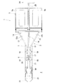
第1実施形態の連続鉢苗移植機1は、圃場を前進するに伴い、溝切部4(溝切部)により圃場2の植付け面に植付け溝を形成しつつ、鉢苗載置部5から引き出された連続鉢苗6(6a,6b)を鉢苗案内部7により後方へ案内しながら鉢苗繰出し部8から該植付け溝内へ繰り出して移植するように構成される。また、連続鉢苗移植機1は、鉢苗載置部5が機台幅方向(図1における上下方向)へ並ぶ2つの鉢苗載置領域5a,5bに区画され、図5および図6に示されるように、各鉢苗載置領域5a,5bから引き出された各連続鉢苗6a,6bを集約しつつ整列させ、整列させた各連続鉢苗6a,6bを1条の植付け溝へ繰り出して移植するように構成したものである。
(First embodiment)
A first embodiment of the present invention will be described with reference to FIGS. For convenience of explanation, the traveling direction of the continuous potted seedling transplanter 1 (the right direction in FIGS. 1, 2, 5, and 6) is defined as the front.
The continuous potted seedling transplanting machine 1 according to the first embodiment moves from the potted seedling placement unit 5 while forming a planting groove on the planting surface of the field 2 by the grooved part 4 (grooved part) as the field advances. The drawn continuous potted seedlings 6 (6a, 6b) are configured to be fed out from the potted seedling feeding part 8 into the planting groove and transplanted while being guided backward by the potted seedling guiding part 7. Moreover, the continuous potted seedling transplanting machine 1 is divided into two potted seedling placement areas 5a and 5b in which the potted seedling placement section 5 is arranged in the machine width direction (vertical direction in FIG. 1). As shown, the continuous potted seedlings 6a and 6b drawn from the potted seedling placement areas 5a and 5b are aligned while being aggregated, and the aligned continuous potted seedlings 6a and 6b are fed into a single planting groove. And configured to be transplanted.

連続鉢苗移植機1は、進行方向の後側(図1および図2における左側)の下面を接地面とする機台3を有する。機台3上には、前から順に、鉢苗載置部5と、該鉢苗載置部5の各鉢苗載置領域5a,5bから引き出された各連続鉢苗6a,6bを集約しつつ整列させ、整列させた各連続鉢苗6a,6bを後方へ向けて案内する鉢苗案内部7と、該鉢苗案内部7により案内した各連続鉢苗6a,6bを連続に繰り出す鉢苗繰出し部8と、が設けられる。なお、図5に示されるように、鉢苗載置部5の各鉢苗載置領域5a,5bには、各連続鉢苗6a,6bを収容する各鉢苗台9a,9bが載置される。鉢苗載置部5は、仕切板等により厳格に区画する必要はなく、鉢苗載置部5に各鉢苗台9a,9bを並べて載置することで、鉢苗載置部5を各鉢苗載置領域5a,5bに区画したものとする。   The continuous potted seedling transplanting machine 1 has a machine base 3 having a lower surface on the rear side in the traveling direction (left side in FIGS. 1 and 2) as a ground contact surface. On the machine base 3, the potted seedling placement unit 5 and the continuous potted seedlings 6 a and 6 b drawn from the potted seedling placement regions 5 a and 5 b of the potted seedling placement unit 5 are gathered in order from the front. While being aligned, the potted seedling guide part 7 that guides the aligned potted seedlings 6a and 6b to the rear, and the potted seedling that continuously feeds the continuous potted seedlings 6a and 6b guided by the potted seedling guide part 7 A feeding unit 8; As shown in FIG. 5, the potted seedling stands 9 a and 9 b that house the continuous potted seedlings 6 a and 6 b are placed in the potted seedling placement areas 5 a and 5 b of the potted seedling placing unit 5. The The potted seedling placement unit 5 does not need to be strictly partitioned by a partition plate or the like, and by placing the potted seedling stands 9a and 9b side by side on the potted seedling placing unit 5, It is assumed that it is partitioned into potted seedling placement areas 5a and 5b.

図1および図2に示されるように、鉢苗案内部7は、各連続鉢苗6a,6bの滑動面を提供する底板12と、該底板12上に突設した左右1対の案内板13とを備えるフレーム11を有する。該フレーム11は、機台3上に固定され、1対の鉢苗案内板13間に仕切用のアングル材14(仕切手段)が設けられる。該アングル材14は、底板12の上面を各鉢苗載置領域5a,5bに相対する2つの領域12a,12bに区画する。各領域12a,12bは、各連続鉢苗6a,6bを円滑に案内できるように各鉢苗載置領域5a,5b側へV字形に拡張されている。また、鉢苗案内部7は、各鉢苗案内板13とアングル材14との間を通過して集約された各連続鉢苗6a,6bを誘導して起立させる姿勢矯正部15と、起立した各連続鉢苗6a,6bを整列させて鉢苗繰出し部8へ向けて案内する案内部16と、を有する。   As shown in FIGS. 1 and 2, the potted seedling guide unit 7 includes a bottom plate 12 that provides a sliding surface for each of the continuous potted seedlings 6 a and 6 b, and a pair of left and right guide plates 13 that protrude from the bottom plate 12. The frame 11 is provided. The frame 11 is fixed on the machine base 3, and an angle member 14 (partitioning means) for partitioning is provided between a pair of potted seedling guide plates 13. The angle member 14 divides the upper surface of the bottom plate 12 into two regions 12a and 12b facing the potted seedling placement regions 5a and 5b. Each area | region 12a, 12b is extended by the V shape to each potted seedling mounting area | region 5a, 5b side so that each continuous potted seedling 6a, 6b can be guided smoothly. Moreover, the potted seedling guide part 7 stood up with the attitude | position correction | amendment part 15 which guide | induces and stands up each continuous potted seedling 6a, 6b aggregated by passing between each potted seedling guide plate 13 and the angle material 14. And a guide unit 16 for aligning the respective continuous potted seedlings 6a and 6b and guiding them toward the potted seedling feeding part 8.

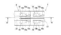
図1に示されるように、鉢苗案内部7は、フレーム11上に立設されてアングル材14の後端部から鉢苗繰出し部8へ前後へ延びる仕切板17(仕切手段)を有する。フレーム11には、左右対称(図1における上下対称)に形成された1対の鉢苗整列部材18,19(鉢苗整列手段)が、仕切板17の前側部分を挟んで機台幅方向(図1における上下方向)両側に対向して設けられる。図3および図4に示されるように、鉢苗整列部材18は、フレームに固定される取付片18aと、該取付片18aに曲げ部を介して連続して仕切板17に対して平行な垂直片18bと、該垂直片18bに曲げ部(稜)18dを介して連続して垂直片18bに対して外側へ傾倒させた傾倒片18cと、からなる。   As shown in FIG. 1, the potted seedling guide portion 7 has a partition plate 17 (partitioning means) that stands on the frame 11 and extends forward and backward from the rear end portion of the angle member 14 to the potted seedling feeding portion 8. A pair of potted seedling alignment members 18 and 19 (potted seedling aligning means) formed symmetrically in the left-right symmetry (vertical symmetry in FIG. 1) are arranged on the frame 11 with the front side portion of the partition plate 17 in the machine width direction ( The vertical direction in FIG. As shown in FIG. 3 and FIG. 4, the potted seedling alignment member 18 includes a mounting piece 18a fixed to the frame, and a vertical line parallel to the partition plate 17 continuously to the mounting piece 18a via a bent portion. It consists of a piece 18b and a tilted piece 18c that is continuously tilted outward with respect to the vertical piece 18b via a bent portion (ridge) 18d.

そして、連続鉢苗移植機1では、鉢苗整列部材18の傾倒片18cが上述した姿勢矯正部15をなし、垂直片18bが上述した案内部16をなす。同様に、鉢苗整列部材19の傾倒片19cが上述した姿勢矯正部15をなし、垂直片19bが上述した案内部16をなす。なお、鉢苗整列部材18の垂直片18aと仕切板17との間隔および鉢苗整列部材19の垂直片19aと仕切板17との間隔は、通過する各連続鉢苗6a,6bの幅に合わせて設定される。   And in the continuous potted seedling transplanting machine 1, the inclined piece 18c of the potted seedling arranging member 18 forms the above-described posture correcting section 15, and the vertical piece 18b forms the above-described guiding section 16. Similarly, the inclined piece 19c of the potted seedling alignment member 19 forms the above-described posture correcting portion 15, and the vertical piece 19b forms the above-described guide portion 16. The distance between the vertical piece 18a of the potted seedling alignment member 18 and the partition plate 17 and the distance between the vertical piece 19a of the potted seedling alignment member 19 and the partition plate 17 are matched to the width of each continuous potted seedling 6a, 6b passing through. Is set.

図1に示されるように、鉢苗繰出し部8は、フレーム20の底面を切欠いて形成した切欠部21を有する。フレーム20には、上述した1対の鉢苗整列部材18,19(鉢苗整列手段)が、仕切板17の後側部分を挟んで機台幅方向(図1における上下方向)両側に対向して設けられる。図1を参照してもわかるように、連続鉢苗移植機1には、連続鉢苗6aが通る経路と連続鉢苗6bが通る経路とが独立しており、鉢苗載置部5から引き出された各連続鉢苗6a,6bは、鉢苗繰出し部8から繰り出される時点まで接触することがないように構成される。なお、鉢苗繰出し部8に設けられる1対の鉢苗整列部材18,19は、上述した鉢苗案内部7に設けられる1対の鉢苗整列部材18,19と、部材18,19間の取付間隔を含めて同一であるので、その詳細な説明を省略する。   As shown in FIG. 1, the potted seedling feeding portion 8 has a cutout portion 21 formed by cutting out the bottom surface of the frame 20. On the frame 20, the pair of potted seedling alignment members 18 and 19 (potted seedling aligning means) described above are opposed to both sides of the machine base width direction (vertical direction in FIG. 1) across the rear portion of the partition plate 17. Provided. As can be seen from FIG. 1, the continuous potted seedling transplanter 1 has a path through which the continuous potted seedling 6 a and a path through which the continuous potted seedling 6 b pass are independent and are drawn from the potted seedling placement unit 5. Each of the continuous potted seedlings 6a and 6b is configured so as not to contact until the time when the potted seedling feeding part 8 is fed. In addition, a pair of potted seedling alignment members 18 and 19 provided in the potted seedling feeding part 8 are between the pair of potted seedling alignment members 18 and 19 provided in the potted seedling guide part 7 and the members 18 and 19. Since it is the same including the mounting interval, its detailed description is omitted.

機台3の接地面には、圃場に植付け溝を形成する上述した溝切部4が設けられる。該溝切部4は、先端部を鋭角に閉じると共に後端部を開放した箱形をなし、後部が鉢苗繰出し部8の下まで延ばされる。また、溝切部4は、左右壁の間隔が、切欠部21の幅よりやや広く形成されており、鉢苗繰出し部58から繰り出された各連続鉢苗6a,6bは、この溝切部4の側壁にも案内されながら、植付け溝へ繰り出される。また、機台3の後端部には、植付け溝に繰り出された各連続鉢苗6a,6bに周辺の土を掻き寄せる1対の培土板30と、該培土板30によって掻き寄せられた土を鎮圧する1対の鎮圧ローラ23と、が設けられる。1対の掻き寄せ板22は、さらに土の掻き寄せを行いたい場合(深植等の場合)に設けられる。なお、機台3の先端部には、ハンドル24を有するスタンド25が設けられ、該スタンド25の下端部には、圃場を滑走可能な車輪26が設けられる。   The ground contact surface of the machine base 3 is provided with the above-described groove cutting portion 4 that forms a planting groove in a farm field. The groove cutting portion 4 has a box shape in which the front end portion is closed at an acute angle and the rear end portion is opened, and the rear portion is extended under the potted seedling feeding portion 8. Further, the groove cutting part 4 is formed such that the interval between the left and right walls is slightly wider than the width of the notch part 21, and the continuous potted seedlings 6 a and 6 b fed out from the potted seedling feeding part 58 are formed in the groove cutting part 4. While being guided by the side wall of the plant, it is fed into the planting groove. In addition, at the rear end of the machine base 3, a pair of cultivating plates 30 that scrape the surrounding soil to the respective continuous potted seedlings 6 a and 6 b fed into the planting grooves, and the soil raked by the cultivating plate 30 And a pair of pressure-reducing rollers 23 for pressure-reducing the pressure. The pair of scraping plates 22 is provided when further soil scraping is desired (in the case of deep planting or the like). A stand 25 having a handle 24 is provided at the front end of the machine base 3, and a wheel 26 capable of sliding on the farm field is provided at the lower end of the stand 25.

次に、第1実施形態の作用を説明する。なお、図5および図6に示されるように、第1実施形態では、鉢苗載置部5に長ネギの各鉢苗台9a,9bを並べて載置し、各鉢苗台9a,9bから引き出された各連続鉢苗6a,6bを圃場に形成した1条の植付け溝へ繰り出して移植する場合を説明する。
まず、ハンドル24を牽いて連続鉢苗移植機1を前進させる(図1における右方向へ移動させる)。この連続鉢苗移植機1の前進に伴い、当該移植機1の溝切部4により圃場の植付け面に植付け溝が形成される。同時に、図1に示されるように、移植機1の鉢苗載置部5の各鉢苗台9a,9bから各連続鉢苗6a,6bが引き出される。
Next, the operation of the first embodiment will be described. As shown in FIG. 5 and FIG. 6, in the first embodiment, the long leek potted seedling stands 9 a and 9 b are placed side by side on the potted seedling placing portion 5 and pulled out from the potted seedling stands 9 a and 9 b. A case will be described in which each continuous potted seedling 6a, 6b is fed into a single planting groove formed in the field and transplanted.
First, the handle 24 is pulled and the continuous potted seedling transplanter 1 is moved forward (moved rightward in FIG. 1). As the continuous potted plant transplanter 1 advances, a planting groove is formed on the planting surface of the field by the groove cutting part 4 of the transplanter 1. At the same time, as shown in FIG. 1, the continuous potted seedlings 6 a and 6 b are drawn out from the potted seedling stands 9 a and 9 b of the potted seedling placement unit 5 of the transplanter 1.

各鉢苗台9a,9bから引き出された各連続鉢苗6a,6bは、底板12上の各領域12a,12bを移動する過程で集約されるが、アングル材14(仕切手段)により各連続鉢苗6a,6bが接触することはない。鉢苗案内部7の1対の鉢苗整列部材18,19(鉢苗整列手段)の各姿勢矯正部15(各傾倒片18c,19c)は、各領域12a,12bを通過した各連続鉢苗6a,6bを起き上がらせるように誘導して起立させる。さらに、鉢苗案内部7の1対の鉢苗整列部材18,19の各案内部16(各垂直片18b,19b)は、起立した各連続鉢苗6a,6bを整列させて鉢苗絞り部8へ向けて案内する。この時、鉢苗案内部7の1対の鉢苗整列部材18,19間を通過する連続鉢苗6a,6b間は仕切板17(仕切手段)により仕切られているので、各連続鉢苗6a,6bが接触することはない。   The continuous potted seedlings 6a and 6b drawn from the potted seedling stands 9a and 9b are gathered in the process of moving the respective regions 12a and 12b on the bottom plate 12, but each continuous pot by the angle material 14 (partitioning means). The seedlings 6a and 6b do not come into contact. Each posture correcting part 15 (each tilted piece 18c, 19c) of the pair of potted seedling alignment members 18, 19 (potted seedling aligning means) of the potted seedling guide part 7 is each continuous potted seedling that has passed through each region 12a, 12b. 6a and 6b are guided and stood up to rise. Furthermore, each guide part 16 (each vertical piece 18b, 19b) of the pair of potted seedling alignment members 18 and 19 of the potted seedling guide part 7 aligns the standing continuous potted seedlings 6a and 6b, and the potted seedling narrowing part. Guide to 8 At this time, since the continuous potted seedlings 6a and 6b passing between the pair of potted seedling alignment members 18 and 19 of the potted seedling guide part 7 are partitioned by the partition plate 17 (partitioning means), each continuous potted seedling 6a , 6b will not touch.

鉢苗案内部7を通過して整列された各連続鉢苗6a,6bは、鉢苗繰出し部8の1対の鉢苗整列部材18,19(鉢苗整列手段)の各案内部16(各垂直片18b,19b)に案内されつつ、当該鉢苗繰出し部8の切欠部21から植付け溝へ繰り出されて移植される。ここで、1対の鉢苗整列部材18,19間を通過する連続鉢苗6a,6b間は仕切板17(仕切手段)により仕切られているため、各連続鉢苗6a,6bが接触することはない。この時、切欠部21から繰り出される連続鉢苗6a,6b間は仕切板17(仕切手段)により仕切られているので、各連続鉢苗6a,6bが接触することはない。   Each of the continuous potted seedlings 6a and 6b aligned through the potted seedling guide part 7 is connected to each guide part 16 (each of the potted seedling aligning means) of the pair of potted seedling aligning members 18 and 19 (potted seedling aligning means). While being guided by the vertical pieces 18b, 19b), the potted seedling feeding part 8 is fed out from the notch 21 to the planting groove and transplanted. Here, since the continuous potted seedlings 6a and 6b passing between the pair of potted seedling alignment members 18 and 19 are partitioned by the partition plate 17 (partitioning means), the continuous potted seedlings 6a and 6b are in contact with each other. There is no. At this time, since the continuous potted seedlings 6a and 6b fed out from the notch 21 are partitioned by the partition plate 17 (partitioning means), the continuous potted seedlings 6a and 6b do not come into contact with each other.

なお、鉢苗繰出し部8における1対の鉢苗整列部材18,19の各姿勢矯正部15(各傾倒片18c,19c)は、各連続鉢苗6a,6bの姿勢を矯正する作用の他、各連続鉢苗6a,6bを円滑に1対の鉢苗整列部材18,19間に導き入れる作用を有する。   In addition, each posture correction | amendment part 15 (each tilting piece 18c, 19c) of a pair of potted seedling arrangement members 18 and 19 in the potted seedling feeding part 8 has the effect | action which corrects the attitude | position of each continuous potted seedling 6a, 6b, Each continuous potted seedling 6a, 6b is smoothly guided between the pair of potted seedling aligning members 18, 19.

第1実施形態では以下の効果を奏する。
第1実施形態によれば、鉢苗載置台5に2つ鉢苗台9a,9bを機台幅方向へ並べて載置し、各鉢苗台9a,9bから引き出した各連続鉢苗6a,6bを鉢苗案内部7により集約しつつ整列させ、該整列させた各連続鉢苗6a,6bを鉢苗繰出し部8から繰り出して1条の植付け溝へ移植することができる。また、各鉢苗台9a,9bから引き出された各連続鉢苗6a,6bは、アングル材14および仕切板14(仕切手段)により、植付け面へ繰り出される時点まで仕切られているので、各連続鉢苗6a,6bが接触することはない。これにより、連続鉢苗6a,6bが絡むようなことがなく、整列した状態を保持したままで連続鉢苗6a,6bを植付け面へ繰り出すことができ、連続鉢苗6a,6bを圃場へ整然と移植することができる。
例えば、長ネギの苗を比較的大きく成長させてから圃場に移植する作型に連続鉢苗6(6a,6b)を適用する場合、畦(1条の植付け溝)に移植することができる苗の数が少なく採算が合わないことから、従来、連続鉢苗移植機による移植が見送られていたが、第1実施形態の連続鉢苗移植機1を使用することで、各鉢体の長ネギの苗が比較的大きく成長した状態の複数列(本実施形態では、2列)の連続鉢苗6a,6bを1条の植付け溝へ整然と移植することができる。これにより、採算性および商品価値を確保しつつ、長ネギの各連続鉢苗6a,6bの移植作業を機械化することが可能になり、移植作業が大幅に効率化されると共に作業者への負担を大幅に軽減することができる。
また、畦に多くの苗を移植するのが有利である場合、1つの鉢体に複数粒で播種した連続鉢苗6a,6bを第1実施形態の連続鉢苗移植機1を使用して複数列(本実施形態では、2列)で畦に移植することで、畦に多くの苗を効率的に移植することができる。
さらに、複数列(本実施形態では、2列)の連続鉢苗6a,6bが同時に覆土、鎮圧されるので、複数列で移植した苗の活着、生育が良好である。
The first embodiment has the following effects.
According to the first embodiment, two potted seedling stands 9a, 9b are placed side by side in the machine width direction on the potted seedling placing stand 5, and each continuous potted seedling 6a, 6b drawn from each potted seedling stand 9a, 9b is placed. Can be aligned while being concentrated by the potted seedling guide unit 7, and the aligned continuous potted seedlings 6 a and 6 b can be fed out from the potted seedling feeding unit 8 and transplanted into one planting groove. Moreover, since each continuous potted seedling 6a, 6b pulled out from each potted seedling stand 9a, 9b is divided by the angle material 14 and the partition plate 14 (partitioning means) until it is drawn out to the planting surface, each continuous The potted seedlings 6a and 6b are not in contact with each other. Thereby, the continuous potted seedlings 6a and 6b are not entangled, and the continuous potted seedlings 6a and 6b can be fed out to the planting surface while maintaining the aligned state. Can be transplanted.
For example, when the continuous potted seedling 6 (6a, 6b) is applied to a pattern in which a long leek seedling is grown to a relatively large size and then transplanted to a field, the seedling that can be transplanted into a cocoon (one row of planting grooves) Because the number is small and the profit is not suitable, conventionally, transplantation by a continuous potted seedling transplanter has been postponed, but by using the continuous potted seedling transplanter 1 of the first embodiment, the seedlings of the long leek of each pot body A plurality of rows (two rows in this embodiment) of the continuous potted seedlings 6a and 6b in a state where the plant has grown relatively large can be orderly transplanted into one planting groove. As a result, it is possible to mechanize the transplanting operation of each of the long leek continuous potted seedlings 6a and 6b while ensuring profitability and commercial value, which greatly improves the efficiency of the transplanting operation and burdens the operator. It can be greatly reduced.
In addition, when it is advantageous to transplant many seedlings in the cocoon, a plurality of continuous potted seedlings 6a and 6b sown in one pot body with a plurality of grains using the continuous potted seedling transplanting machine 1 of the first embodiment. By transplanting the cocoon in rows (in this embodiment, two rows), many seedlings can be efficiently transplanted into the cocoon.
Furthermore, since a plurality of rows (in this embodiment, two rows) of continuous potted seedlings 6a and 6b are simultaneously soiled and crushed, the seedlings transplanted in a plurality of rows are well established and grown.

なお、実施形態は、上述した第1実施形態に限定されるのもではなく、例えば、次のように構成してもよい。
第1実施形態では、連続鉢苗移植機1を使用して長ネギの苗を移植する場合を説明したが、例えば、葉ネギ、水菜あるいは花の苗等の移植に連続鉢苗移植機1を適用することができる。
第1実施形態では、ハンドル24を牽いて連続鉢苗移植機1を前進させたが、例えば、当該移植機1をトラクタに連結して牽引させることができる。
In addition, embodiment is not limited to 1st Embodiment mentioned above, For example, you may comprise as follows.
In the first embodiment, the case of transplanting a long onion seedling using the continuous potted seedling transplanting machine 1 has been described. For example, the continuous potted seedling transplanting machine 1 is applied to transplanting leaf leek, mizuna or a flower seedling. can do.
In the first embodiment, the continuous potted seedling transplanter 1 is moved forward by checking the handle 24. For example, the transplanter 1 can be connected to a tractor and pulled.

(第2実施形態)
次に、図7に基いて第2実施形態を説明する。ここでは、明細書の記載を簡潔にするために、上述した第1実施形態と同一あるいは相当の構成要素については、同一の名称及び符号を付与すると共にその詳細な説明を省略する。
図7に示されるように、第2実施形態の連続鉢苗移植機31は、鉢苗載置部5が機台幅方向(図7における上下方向)へ並ぶ3つの鉢苗載置領域5a,5b,5cに区画され、各鉢苗載置領域5a,5b,5cから引き出された各連続鉢苗6a,6b,6cを集約しつつ整列させ、整列させた各連続鉢苗6a,6b,6cを1条の植付け溝へ繰り出して移植するように構成したものである。
(Second Embodiment)
Next, a second embodiment will be described based on FIG. Here, in order to simplify the description of the specification, the same or equivalent components as those in the first embodiment described above are given the same names and reference numerals and detailed descriptions thereof are omitted.
As shown in FIG. 7, the continuous potted seedling transplanting machine 31 according to the second embodiment includes three potted seedling placement areas 5 a in which the potted seedling placement units 5 are arranged in the machine width direction (vertical direction in FIG. 7). Each of the continuous potted seedlings 6a, 6b, 6c, which are partitioned into 5b, 5c, are aligned while aggregating the continuous potted seedlings 6a, 6b, 6c drawn from the potted seedling placement areas 5a, 5b, 5c. Is configured to be fed into a single planting groove and transplanted.

なお、鉢苗載置部5の各鉢苗載置領域5a,5b,5cには、各連続鉢苗6a,6b,6cを収容する各鉢苗台9a,9b,9cが載置される。鉢苗載置部5は、仕切板等により厳格に区画する必要はなく、鉢苗載置部5に各鉢苗台9a,9b,9cを並べて載置することで、鉢苗載置部5を各鉢苗載置領域5a,5b,5cに区画したものとする。鉢苗案内部7のフレーム11には、1対の鉢苗案内板13間に仕切用のアングル材32,33(仕切手段)が設けられる。これらアングル材32,33は、底板12の上面を各鉢苗載置領域5a,5b,5cに相対する3つの領域12a,12b,12cに区画する。   In addition, in each potted seedling placement area 5a, 5b, 5c of the potted seedling placement unit 5, the potted seedling stands 9a, 9b, 9c that house the continuous potted seedlings 6a, 6b, 6c are placed. The potted seedling placement unit 5 does not need to be strictly partitioned by a partition plate or the like, and the potted seedling placement unit 5 is arranged by placing the potted seedling stands 9a, 9b, 9c side by side on the potted seedling placement unit 5. Is partitioned into each potted seedling placement region 5a, 5b, 5c. The frame 11 of the potted seedling guide unit 7 is provided with partitioning angle members 32 and 33 (partitioning means) between a pair of potted seedling guide plates 13. These angle members 32 and 33 partition the upper surface of the bottom plate 12 into three regions 12a, 12b, and 12c that face the potted seedling placement regions 5a, 5b, and 5c.

鉢苗案内部7は、各鉢苗案内板13と各アングル材32,33との間およびアングル材32,33間を通過して集約された各連続鉢苗6a,6b,6cを誘導して起立させる姿勢矯正部15と、起立した各連続鉢苗6a,6bを整列させて鉢苗繰出し部8へ向けて案内する案内部16と、を有する。また、鉢苗案内部7は、フレーム11上に立設されて各アングル材32,33の後方から鉢苗繰出し部8へ前後へ延びる仕切板34,35(仕切手段)を有する。さらに、フレーム11には、1対の鉢苗整列部材18,19(鉢苗整列手段)が、仕切板34,35の前側部分を挟んで対向して設けられる。なお、鉢苗整列部材18の垂直片18aと仕切板34との間隔、仕切板34,35間の間隔ならびに鉢苗整列部材19の垂直片19aと仕切板35との間隔は、通過する各連続鉢苗6a,6b,6cの幅に合わせて設定される。   The potted seedling guide unit 7 guides the continuous potted seedlings 6a, 6b, and 6c that are aggregated by passing between the potted seedling guide plates 13 and the angle members 32 and 33 and between the angle members 32 and 33. It has the posture correction part 15 to stand up, and the guide part 16 which aligns each standing continuous potted seedling 6a, 6b and guides it toward the potted seedling feeding part 8. In addition, the potted seedling guide portion 7 has partition plates 34 and 35 (partitioning means) that are erected on the frame 11 and extend back and forth from the rear of each angle member 32 and 33 to the potted seedling feeding portion 8. Further, a pair of potted seedling alignment members 18 and 19 (potted seedling aligning means) are provided on the frame 11 so as to face each other with the front portions of the partition plates 34 and 35 interposed therebetween. Note that the interval between the vertical piece 18a of the potted seedling alignment member 18 and the partition plate 34, the interval between the partition plates 34 and 35, and the interval between the vertical piece 19a of the potted seedling alignment member 19 and the partition plate 35 pass through each continuous line. It is set according to the width of the potted seedlings 6a, 6b, 6c.

鉢苗繰出し部8のフレーム20には、上述した1対の鉢苗整列部材18,19(鉢苗整列手段)が、仕切板34,35の後側部分を挟んで対向して設けられる。図6を参照してもわかるように、連続鉢苗移植機31には、連続鉢苗6aが通る経路、連続鉢苗6bが通る経路ならびに連続鉢苗6cが通る経路が独立しており、鉢苗載置部5から引き出された各連続鉢苗6a,6b,6cは、鉢苗繰出し部8から繰り出される時点まで接触することがないように構成される。   The pair of potted seedling alignment members 18 and 19 (potted seedling aligning means) described above are provided on the frame 20 of the potted seedling feeding portion 8 so as to face each other with the rear portions of the partition plates 34 and 35 interposed therebetween. As can be seen from FIG. 6, the continuous potted seedling transplanter 31 has independent paths for the continuous potted seedling 6a, the path for the continuous potted seedling 6b, and the path for the continuous potted seedling 6c. Each continuous potted seedling 6a, 6b, 6c pulled out from the seedling placing part 5 is configured so as not to contact until it is drawn out from the potted seedling feeding part 8.

第2実施形態の連続鉢苗移植機31によれば、第1実施形態の連続鉢苗移植機1と同一の作用効果を得ることができる。
また、第2実施形態の連続鉢苗移植機31は、3つの各鉢苗台9a,9b,9cから引き出した各連続鉢苗6a,6b,6cを鉢苗案内部7により集約しつつ整列させ、該整列させた各連続鉢苗6a,6b,6cを鉢苗繰出し部8から繰り出して1条の植付け溝へ移植することができるので、畦により多くの苗を効率的に移植することができる。
According to the continuous potted seedling transplanter 31 of the second embodiment, the same operational effects as the continuous potted seedling transplanter 1 of the first embodiment can be obtained.
Further, the continuous potted seedling transplanting machine 31 of the second embodiment aligns the continuous potted seedlings 6a, 6b, 6c drawn from the three potted seedling stands 9a, 9b, 9c while concentrating them by the potted seedling guide unit 7. Since each of the aligned continuous potted seedlings 6a, 6b, 6c can be fed out from the potted seedling feeding part 8 and transplanted into a single planting groove, more seedlings can be efficiently transplanted into the cocoon. .

(第3実施形態)
次に、図8に基いて第3実施形態を説明する。ここでは、明細書の記載を簡潔にするために、上述した第1実施形態及び第2実施形態と同一あるいは相当の構成要素については、同一の名称及び符号を付与すると共にその詳細な説明を省略する。
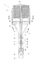
図8に示されるように、第3実施形態の連続鉢苗移植機33は、鉢苗載置部5が機台幅方向(図8における上下方向)へ並ぶ2つの鉢苗載置領域5a,5bに区画され、各鉢苗載置領域5a,5bから引き出された各連続鉢苗6a,6bを集約しつつ整列させ、整列させた各連続鉢苗6a,6bを1条の植付け溝へ繰り出して移植するように構成したものである。なお、鉢苗載置部5の各鉢苗載置領域5a,5bには、各連続鉢苗6a,6bを収容する各鉢苗台9a,9bが載置される。
(Third embodiment)
Next, a third embodiment will be described based on FIG. Here, in order to simplify the description of the specification, the same or equivalent components as those in the first embodiment and the second embodiment described above are given the same names and reference numerals and detailed descriptions thereof are omitted. To do.
As shown in FIG. 8, the continuous potted seedling transplanting machine 33 according to the third embodiment includes two potted seedling placement regions 5 a, in which the potted seedling placement unit 5 is arranged in the machine width direction (vertical direction in FIG. 8). The continuous potted seedlings 6a and 6b, which are partitioned into 5b and pulled out from the potted seedling placement areas 5a and 5b, are aligned while being aggregated, and the aligned continuous potted seedlings 6a and 6b are fed into one planting groove. And configured to be transplanted. In addition, in the potted seedling placement areas 5a and 5b of the potted seedling placement unit 5, potted seedling stands 9a and 9b that house the continuous potted seedlings 6a and 6b are placed.

第3実施形態において、鉢苗載置部5は、仕切板等により厳格に区画する必要はなく、鉢苗載置部5に各鉢苗台9a,9bを並べて載置することで、鉢苗載置部5を各鉢苗載置領域5a,5bに区画したものとする。鉢苗案内部7のフレーム11には、1対の鉢苗案内板13間に仕切用のアングル材14(仕切手段)が設けられる。アングル材14は、底板12の上面を各鉢苗載置領域5a,5bに相対する3つの領域12a,12bに区画する。   In 3rd Embodiment, the potted seedling mounting part 5 does not need to partition | separate strictly with a partition plate etc., and each potted seedling stand 9a, 9b is mounted side by side in the potted seedling mounting part 5, and potted seedling It is assumed that the placement unit 5 is partitioned into the potted seedling placement regions 5a and 5b. The frame 11 of the potted seedling guide unit 7 is provided with an angle member 14 (partitioning means) for partitioning between a pair of potted seedling guide plates 13. The angle member 14 divides the upper surface of the bottom plate 12 into three regions 12a and 12b facing the potted seedling placement regions 5a and 5b.

鉢苗案内部7は、各鉢苗案内板13とアングル材14との間を通過して集約された各連続鉢苗6a,6bを誘導して起立させる。起立直後に、苗は整列されて鉢苗繰出し部8へ向けて案内する案内部16から植溝へ繰り出される。
鉢苗繰出し部8のフレーム20には、上述した1対の鉢苗整列部材18,19(鉢苗整列手段)が、切欠部21を挟んで対向して設けられる。図9を参照してもわかるように、連続鉢苗移植機33には、連続鉢苗6aが通る経路、連続鉢苗6bが通る経路が独立しており、鉢苗載置部5から引き出された各連続鉢苗6a,6bは、鉢苗繰出し部8から繰り出される時点まで接触することがないように構成される。
The potted seedling guide unit 7 guides and stands up the continuous potted seedlings 6a and 6b that are aggregated by passing between the potted seedling guide plates 13 and the angle members 14. Immediately after standing, the seedlings are aligned and fed out from the guide unit 16 that guides the seedlings toward the potted seedling feeding unit 8.
The pair of potted seedling alignment members 18 and 19 (potted seedling aligning means) described above are provided on the frame 20 of the potted seedling feeding part 8 so as to face each other with the notch 21 interposed therebetween. As can be seen by referring to FIG. 9, the continuous potted seedling transplanter 33 has a path through which the continuous potted seedling 6 a and a path through which the continuous potted seedling 6 b pass are independent and are drawn from the potted seedling placement unit 5. Each of the continuous potted seedlings 6a and 6b is configured not to come into contact until the time when the potted seedling feeding part 8 is fed out.

第3実施形態の連続鉢苗移植機33によれば、第1実施形態の連続鉢苗移植機1と同一の作用効果を得ることができる。   According to the continuous potted seedling transplanter 33 of the third embodiment, the same operational effects as the continuous potted seedling transplanter 1 of the first embodiment can be obtained.

第1実施形態の連続鉢苗移植機の平面図である。It is a top view of the continuous potted seedling transplanter of 1st Embodiment. 第1実施形態の連続鉢苗移植機の右側面図である。It is a right view of the continuous potted seedling transplanter of 1st Embodiment. 図1における鉢苗整列手段を拡大して示した図である。It is the figure which expanded and showed the potted seedling arrangement means in FIG. 図3におけるA−A矢視図である。It is an AA arrow line view in FIG. 第1実施形態の連続鉢苗移植機を使用して、長ネギを育苗した連続鉢苗を移植する態様を示す平面図である。It is a top view which shows the aspect which transplants the continuous potted seedling which grew the long leek using the continuous potted seedling transplanting machine of 1st Embodiment. 第1実施形態の連続鉢苗移植機を使用して、長ネギを育苗した連続鉢苗を移植する態様を示す右側面図である。It is a right view which shows the aspect which transplants the continuous potted seedling which grew the long leek using the continuous potted seedling transplanting machine of 1st Embodiment. 第2実施形態の連続鉢苗移植機を使用して、長ネギを育苗した連続鉢苗を移植する態様を示す平面図である。It is a top view which shows the aspect which transplants the continuous potted seedling which grew the long leek using the continuous potted seedling transplanting machine of 2nd Embodiment. 第3実施形態の連続鉢苗移植機の平面図である。It is a top view of the continuous potted seedling transplanting machine of 3rd Embodiment. 第3実施形態の連続鉢苗移植機を使用して、長ネギを育苗した連続鉢苗を移植する態様を示す平面図である。It is a top view which shows the aspect which transplants the continuous potted seedling which grew the long leek using the continuous potted seedling transplanting machine of 3rd Embodiment.

符号の説明Explanation of symbols

1 連続鉢苗移植機、2 圃場、3 機台、4 溝切部、5 鉢苗載置部、5a,5b 鉢苗載置領域、6a,6b 連続鉢苗、7 鉢苗案内部、8 鉢苗繰出し部、14 アングル材(仕切手段)、15 姿勢矯正部、16 案内部、17 仕切板(仕切手段)、18,19 鉢苗整列部材 1 continuous potted seedling transplanting machine, 2 fields, 3 machine stands, 4 grooving section, 5 potted seedling mounting section, 5a, 5b potted seedling mounting area, 6a, 6b continuous potted seedling, 7 potted seedling guide section, 8 pots Seedling feeding part, 14 Angle material (partitioning means), 15 Posture correction part, 16 Guide part, 17 Partition plate (partitioning means), 18, 19 Potted seedling alignment member

Claims (7)

進行方向後側の下面を接地面とした機台上に、その進行方向前側から順次、連続鉢苗を載置する鉢苗載置部と、該鉢苗載置部から引き出された前記連続鉢苗を1列に整列させて案内する鉢苗案内部と、該鉢苗案内部から植付け面へ前記連続鉢苗を繰り出す鉢苗繰出し部と、が設けられ、さらに、前記機台の接地面に、圃場に植付け溝を形成する溝切部が設けられる連続鉢苗移植機であって、
前記鉢苗載置部が機台幅方向へ並ぶ複数の鉢苗載置領域に区画され、
さらに、前記鉢苗案内部に設けられ、各鉢苗載置領域から引き出された各連続鉢苗を集約しつつ整列させる鉢苗整列手段と、
を有することを特徴とする連続鉢苗移植機。
A potted seedling placement part for placing continuous potted seedlings sequentially from the front side of the traveling direction on a machine base having a lower surface on the rear side in the traveling direction as a ground contact surface, and the continuous pots drawn from the potted seedling placement part A potted seedling guide part for aligning and guiding the seedlings in a row, and a potted seedling feeding part for feeding the continuous potted seedlings from the potted seedling guide part to the planting surface, and further, on the grounding surface of the machine base , A continuous potted seedling transplanting machine provided with a groove cutting part to form a planting groove in the field,
The potted seedling placement section is divided into a plurality of potted seedling placement areas arranged in the machine width direction,
Furthermore, the potted seedling alignment means provided in the potted seedling guide unit, and aligning while aligning each continuous potted seedling drawn from each potted seedling placement region,
A continuous potted seedling transplanter characterized by comprising:
さらに、前記鉢苗案内部から前記鉢苗繰出し部まで延び、前記鉢苗整列手段により整列させた前記連続鉢苗の隣り合う前記連続鉢苗間を仕切る仕切手段を有することを特徴とする連続鉢苗移植機。 Furthermore, it has a partitioning means that extends from the potted seedling guide part to the potted seedling feeding part and partitions the adjacent potted seedlings of the continuous potted seedlings aligned by the potted seedling arranging means. Seedling transplanter. 前記鉢苗整列手段は、集約された前記連続鉢苗の通過を許容する間隔をあけて対向配置される1対の鉢苗整列部材を有することを特徴とする請求項1に記載の連続鉢苗移植機。 2. The continuous potted seedling according to claim 1, wherein the potted seedling arranging means includes a pair of potted seedling aligning members arranged to face each other with an interval that allows passage of the aggregated continuous potted seedlings. Transplanter. 前記鉢苗整列手段の各鉢苗整列部材は、前記連続鉢苗の姿勢を矯正する姿勢矯正部と、姿勢が矯正された前記連続鉢苗を整列させて前記鉢苗繰出し部へ向けて案内する案内部と、を有することを特徴とする請求項1−3に記載の連続鉢苗移植機。 Each potted seedling alignment member of the potted seedling aligning means aligns the continuous potted seedling with a posture correcting unit that corrects the posture of the continuous potted seedling and guides it toward the potted seedling feeding unit. The continuous potted seedling transplanting machine according to claim 1, further comprising a guide unit. さらに、前記1対の鉢苗整列部材が前記鉢苗繰出し部に設けられることを特徴とする請求項1−4のいずれかに記載の連続鉢苗移植機。 5. The continuous potted seedling transplanting machine according to claim 1, wherein the pair of potted seedling arranging members is provided in the potted seedling feeding portion. 連続鉢苗移植機を移動させて該移植機の溝切部により圃場に植付け溝を形成しつつ鉢苗載置部から引き出された連続鉢苗を前記植付け溝へ繰り出して移植する方法であって、
前記鉢苗載置部を機台幅方向へ並ぶ複数の鉢苗載置領域に区画しておいて、
各鉢苗載置領域から引き出された各連続鉢苗を集約しつつ整列させ、該整列させた各連続鉢苗を前記植付け溝へ繰出して移植することを特徴とする連続鉢苗移植方法。
It is a method of moving a continuous potted seedling transplanting machine and drawing out a continuous potted seedling drawn from a potted seedling placing part into the planting groove while forming a planting groove in the field by the groove cutting part of the transplanting machine. ,
Dividing the potted seedling placement part into a plurality of potted seedling placement areas arranged in the machine width direction,
A continuous potted seedling transplanting method characterized in that the continuous potted seedlings drawn from each potted seedling placement region are aligned while being aggregated, and the aligned continuous potted seedlings are fed into the planting groove and transplanted.
整列させた前記連続鉢苗の隣り合う前記連続鉢苗間を仕切板により仕切りつつ、各連続鉢苗を前記植付け溝へ繰出して移植することを特徴とする請求項6に記載の連続鉢苗移植方法。 The continuous potted seedling transplantation according to claim 6, wherein each continuous potted seedling is fed and transplanted to the planting groove while the adjacent potted seedlings adjacent to each other of the aligned continuous potted seedlings are partitioned by a partition plate. Method.
JP2008253675A 2008-09-30 2008-09-30 Continuous potted seedling transplanter Active JP5215801B2 (en)

Priority Applications (1)

Application Number Priority Date Filing Date Title
JP2008253675A JP5215801B2 (en) 2008-09-30 2008-09-30 Continuous potted seedling transplanter

Applications Claiming Priority (1)

Application Number Priority Date Filing Date Title
JP2008253675A JP5215801B2 (en) 2008-09-30 2008-09-30 Continuous potted seedling transplanter

Publications (2)

Publication Number Publication Date
JP2010081853A true JP2010081853A (en) 2010-04-15
JP5215801B2 JP5215801B2 (en) 2013-06-19

Family

ID=42246439

Family Applications (1)

Application Number Title Priority Date Filing Date
JP2008253675A Active JP5215801B2 (en) 2008-09-30 2008-09-30 Continuous potted seedling transplanter

Country Status (1)

Country Link
JP (1) JP5215801B2 (en)

Cited By (1)

* Cited by examiner, † Cited by third party
Publication number Priority date Publication date Assignee Title
JP2016171787A (en) * 2015-03-17 2016-09-29 大分県 Growing method of welsh onion large seedling

Citations (5)

* Cited by examiner, † Cited by third party
Publication number Priority date Publication date Assignee Title
JPS5681609U (en) * 1979-11-30 1981-07-02
JPH07213115A (en) * 1994-02-03 1995-08-15 Nippon Beet Sugar Mfg Co Ltd Seedling transplanter for continuously assembled multi-row pot and transplantation of continuously assembled seedling pot by the transplanter
JP3016320U (en) * 1995-03-29 1995-10-03 清貴 鈴木 Seedling transplanter for vegetables
JPH09285210A (en) * 1996-04-22 1997-11-04 Wadou Sangyo Kk Seedling planter for field
JP3092397U (en) * 2002-08-28 2003-03-07 日本甜菜製糖株式会社 Ground-type transplanter

Patent Citations (5)

* Cited by examiner, † Cited by third party
Publication number Priority date Publication date Assignee Title
JPS5681609U (en) * 1979-11-30 1981-07-02
JPH07213115A (en) * 1994-02-03 1995-08-15 Nippon Beet Sugar Mfg Co Ltd Seedling transplanter for continuously assembled multi-row pot and transplantation of continuously assembled seedling pot by the transplanter
JP3016320U (en) * 1995-03-29 1995-10-03 清貴 鈴木 Seedling transplanter for vegetables
JPH09285210A (en) * 1996-04-22 1997-11-04 Wadou Sangyo Kk Seedling planter for field
JP3092397U (en) * 2002-08-28 2003-03-07 日本甜菜製糖株式会社 Ground-type transplanter

Cited By (1)

* Cited by examiner, † Cited by third party
Publication number Priority date Publication date Assignee Title
JP2016171787A (en) * 2015-03-17 2016-09-29 大分県 Growing method of welsh onion large seedling

Also Published As

Publication number Publication date
JP5215801B2 (en) 2013-06-19

Similar Documents

Publication Publication Date Title
JP5577552B2 (en) Agricultural machines that can be fertilized
AU2007211897B2 (en) Method and apparatus for seeding canola and flax
KR101557365B1 (en) potato planter
JP2016526902A (en) Equipment for planting and processing seedlings of agricultural plants
JP2011142902A (en) Hydroponic method
JP5215801B2 (en) Continuous potted seedling transplanter
JP5209335B2 (en) Continuous potted seedling transplanting machine for dense planting in soft and soft fields
CN202050666U (en) Film mulching cultivation seeder
JP6126486B2 (en) Continuous potted seedling transplanter and crop production method
CN202857291U (en) Special transplanting machine for rape
KR101360222B1 (en) The connected pot for hydroponics and the method of raising seedlings using the same
WO2013066250A1 (en) An agricultural machine provided with a displaceable implement section
JP5035989B2 (en) Transplanting method and transplanter to cultivation bench
KR102274592B1 (en) A seeding machine
CN203040165U (en) Crop transplanting and seeding machine
JP5212831B2 (en) Planting method and apparatus
JP3242976U (en) Seed sowing ruler
JP3016320U (en) Seedling transplanter for vegetables
RU2604290C1 (en) Method of potatoes planting
JP7136989B2 (en) Continuous pot seedling transplanter and crop production method
RU2437267C1 (en) Combined ploughshare
JP6720782B2 (en) How to create mixed seedlings
JP6689086B2 (en) Simultaneous molding planting groove seedling transplanting machine
CN202183960U (en) Potato planter
JP6285886B2 (en) Nursery pot, nursery method and unit type soiled seedling

Legal Events

Date Code Title Description
A621 Written request for application examination

Free format text: JAPANESE INTERMEDIATE CODE: A621

Effective date: 20100430

A977 Report on retrieval

Free format text: JAPANESE INTERMEDIATE CODE: A971007

Effective date: 20111117

A131 Notification of reasons for refusal

Free format text: JAPANESE INTERMEDIATE CODE: A131

Effective date: 20111207

A521 Written amendment

Free format text: JAPANESE INTERMEDIATE CODE: A523

Effective date: 20120131

A131 Notification of reasons for refusal

Free format text: JAPANESE INTERMEDIATE CODE: A131

Effective date: 20120606

A521 Written amendment

Free format text: JAPANESE INTERMEDIATE CODE: A523

Effective date: 20120731

TRDD Decision of grant or rejection written
A01 Written decision to grant a patent or to grant a registration (utility model)

Free format text: JAPANESE INTERMEDIATE CODE: A01

Effective date: 20130206

A61 First payment of annual fees (during grant procedure)

Free format text: JAPANESE INTERMEDIATE CODE: A61

Effective date: 20130301

R150 Certificate of patent or registration of utility model

Ref document number: 5215801

Country of ref document: JP

Free format text: JAPANESE INTERMEDIATE CODE: R150

Free format text: JAPANESE INTERMEDIATE CODE: R150

FPAY Renewal fee payment (event date is renewal date of database)

Free format text: PAYMENT UNTIL: 20160308

Year of fee payment: 3