JP2010080429A - Ion source - Google Patents
Ion source Download PDFInfo
- Publication number
- JP2010080429A JP2010080429A JP2009122675A JP2009122675A JP2010080429A JP 2010080429 A JP2010080429 A JP 2010080429A JP 2009122675 A JP2009122675 A JP 2009122675A JP 2009122675 A JP2009122675 A JP 2009122675A JP 2010080429 A JP2010080429 A JP 2010080429A
- Authority
- JP
- Japan
- Prior art keywords
- plasma generation
- aluminum
- electrode
- plasma
- hot cathode
- Prior art date
- Legal status (The legal status is an assumption and is not a legal conclusion. Google has not performed a legal analysis and makes no representation as to the accuracy of the status listed.)
- Granted
Links
- 229910052782 aluminium Inorganic materials 0.000 claims abstract description 149
- XAGFODPZIPBFFR-UHFFFAOYSA-N aluminium Chemical compound [Al] XAGFODPZIPBFFR-UHFFFAOYSA-N 0.000 claims abstract description 98
- 239000000463 material Substances 0.000 claims abstract description 53
- 239000011737 fluorine Substances 0.000 claims abstract description 38
- 229910052731 fluorine Inorganic materials 0.000 claims abstract description 38
- 238000010884 ion-beam technique Methods 0.000 claims abstract description 29
- PXGOKWXKJXAPGV-UHFFFAOYSA-N Fluorine Chemical compound FF PXGOKWXKJXAPGV-UHFFFAOYSA-N 0.000 claims abstract 3
- 150000002500 ions Chemical class 0.000 claims description 69
- -1 aluminum ions Chemical class 0.000 claims description 66
- 239000012212 insulator Substances 0.000 claims description 9
- 239000000126 substance Substances 0.000 claims description 4
- 238000010292 electrical insulation Methods 0.000 claims description 3
- 239000011810 insulating material Substances 0.000 claims 1
- 239000002245 particle Substances 0.000 description 45
- 239000007789 gas Substances 0.000 description 28
- 238000004544 sputter deposition Methods 0.000 description 18
- YCKRFDGAMUMZLT-UHFFFAOYSA-N Fluorine atom Chemical compound [F] YCKRFDGAMUMZLT-UHFFFAOYSA-N 0.000 description 16
- 238000010438 heat treatment Methods 0.000 description 16
- 230000000694 effects Effects 0.000 description 14
- 230000003628 erosive effect Effects 0.000 description 12
- 238000000605 extraction Methods 0.000 description 7
- KRHYYFGTRYWZRS-UHFFFAOYSA-M Fluoride anion Chemical compound [F-] KRHYYFGTRYWZRS-UHFFFAOYSA-M 0.000 description 3
- AZDRQVAHHNSJOQ-UHFFFAOYSA-N alumane Chemical group [AlH3] AZDRQVAHHNSJOQ-UHFFFAOYSA-N 0.000 description 3
- 238000004519 manufacturing process Methods 0.000 description 3
- TWNQGVIAIRXVLR-UHFFFAOYSA-N oxo(oxoalumanyloxy)alumane Chemical compound O=[Al]O[Al]=O TWNQGVIAIRXVLR-UHFFFAOYSA-N 0.000 description 3
- 229910018072 Al 2 O 3 Inorganic materials 0.000 description 2
- PIGFYZPCRLYGLF-UHFFFAOYSA-N Aluminum nitride Chemical compound [Al]#N PIGFYZPCRLYGLF-UHFFFAOYSA-N 0.000 description 2
- 239000000956 alloy Substances 0.000 description 2
- 229910045601 alloy Inorganic materials 0.000 description 2
- WTEOIRVLGSZEPR-UHFFFAOYSA-N boron trifluoride Chemical compound FB(F)F WTEOIRVLGSZEPR-UHFFFAOYSA-N 0.000 description 2
- 238000010891 electric arc Methods 0.000 description 2
- 239000000284 extract Substances 0.000 description 2
- 238000005468 ion implantation Methods 0.000 description 2
- 230000007935 neutral effect Effects 0.000 description 2
- 239000003870 refractory metal Substances 0.000 description 2
- HBMJWWWQQXIZIP-UHFFFAOYSA-N silicon carbide Chemical compound [Si+]#[C-] HBMJWWWQQXIZIP-UHFFFAOYSA-N 0.000 description 2
- ABTOQLMXBSRXSM-UHFFFAOYSA-N silicon tetrafluoride Chemical compound F[Si](F)(F)F ABTOQLMXBSRXSM-UHFFFAOYSA-N 0.000 description 2
- 239000000758 substrate Substances 0.000 description 2
- 239000010936 titanium Substances 0.000 description 2
- ZOKXTWBITQBERF-UHFFFAOYSA-N Molybdenum Chemical compound [Mo] ZOKXTWBITQBERF-UHFFFAOYSA-N 0.000 description 1
- RTAQQCXQSZGOHL-UHFFFAOYSA-N Titanium Chemical compound [Ti] RTAQQCXQSZGOHL-UHFFFAOYSA-N 0.000 description 1
- 238000004140 cleaning Methods 0.000 description 1
- 238000007865 diluting Methods 0.000 description 1
- 239000003085 diluting agent Substances 0.000 description 1
- 238000007599 discharging Methods 0.000 description 1
- 239000001307 helium Substances 0.000 description 1
- 229910052734 helium Inorganic materials 0.000 description 1
- SWQJXJOGLNCZEY-UHFFFAOYSA-N helium atom Chemical compound [He] SWQJXJOGLNCZEY-UHFFFAOYSA-N 0.000 description 1
- 239000007943 implant Substances 0.000 description 1
- 238000009413 insulation Methods 0.000 description 1
- 229910052750 molybdenum Inorganic materials 0.000 description 1
- 239000011733 molybdenum Substances 0.000 description 1
- 230000009257 reactivity Effects 0.000 description 1
- 230000001846 repelling effect Effects 0.000 description 1
- 238000000926 separation method Methods 0.000 description 1
- 229910010271 silicon carbide Inorganic materials 0.000 description 1
- 229910052715 tantalum Inorganic materials 0.000 description 1
- GUVRBAGPIYLISA-UHFFFAOYSA-N tantalum atom Chemical compound [Ta] GUVRBAGPIYLISA-UHFFFAOYSA-N 0.000 description 1
- PPMWWXLUCOODDK-UHFFFAOYSA-N tetrafluorogermane Chemical compound F[Ge](F)(F)F PPMWWXLUCOODDK-UHFFFAOYSA-N 0.000 description 1
- 229910052719 titanium Inorganic materials 0.000 description 1
Images

Classifications
-
- H—ELECTRICITY
- H01—ELECTRIC ELEMENTS
- H01J—ELECTRIC DISCHARGE TUBES OR DISCHARGE LAMPS
- H01J27/00—Ion beam tubes
- H01J27/02—Ion sources; Ion guns
- H01J27/08—Ion sources; Ion guns using arc discharge
- H01J27/14—Other arc discharge ion sources using an applied magnetic field
Abstract
Description
この発明は、例えば、アルミニウムイオンを炭化ケイ素(SiC)基板等のターゲットに注入するイオン注入装置等に用いられるものであって、アルミニウムイオンを含むイオンビームを発生させるイオン源に関する。 The present invention relates to an ion source that generates an ion beam containing aluminum ions, for example, used in an ion implantation apparatus that implants aluminum ions into a target such as a silicon carbide (SiC) substrate.
この種のイオン源の一例が特許文献1に記載されている。 An example of this type of ion source is described in Patent Document 1.
この特許文献1に記載の従来のイオン源は、イオン化室内に、プラズマの生成・閉じ込め用の部品である電極(陰極)および反跳プレートとは別に、アルミニウム含有物質(例えば酸化アルミニウム)のプレートを設けておき、フッ化物ガス(例えば四フッ化ケイ素)を電離させて生成したプラズマによって当該アルミニウム含有物質のプレートを浸食させて、アルミニウムイオンをプラズマ中に放出させるものである。 In the conventional ion source described in Patent Document 1, a plate of an aluminum-containing material (for example, aluminum oxide) is provided in an ionization chamber separately from an electrode (cathode) and a recoil plate that are components for generating and confining plasma. The aluminum-containing material plate is eroded by plasma generated by ionizing a fluoride gas (for example, silicon tetrafluoride), and aluminum ions are released into the plasma.
上記従来のイオン源においては、プラズマの生成・閉じ込め用の部品とは別に、アルミニウムイオン生成専用のアルミニウム含有物質のプレートを特別に設ける必要があるので、そのぶん部品点数が増えると共に構造が複雑になるという課題がある。 In the conventional ion source described above, it is necessary to provide a special aluminum-containing material plate dedicated to the generation of aluminum ions, in addition to the plasma generation and confinement components, so that the number of parts increases and the structure becomes complicated. There is a problem of becoming.
そこでこの発明は、アルミニウムイオンを含むイオンビームを発生させるイオン源において、部品点数の削減および構造の簡素化を可能にすることを主たる目的としている。 Accordingly, the main object of the present invention is to enable the reduction of the number of parts and the simplification of the structure in an ion source for generating an ion beam containing aluminum ions.
この発明に係るイオン源の一つは、アルミニウムイオンを含むイオンビームを発生させるイオン源であって、陽極を兼ねていて内部でプラズマを生成するための容器であって、フッ素を含むイオン化ガスが導入されるプラズマ生成容器と、前記プラズマ生成容器内の一方側に、前記プラズマ生成容器から電気的に絶縁して設けられた熱陰極と、前記プラズマ生成容器内の他方側に、前記プラズマ生成容器から電気的に絶縁して、かつ前記熱陰極に対向させて設けられていて、前記プラズマ生成容器の電位を基準にして負電圧が印加される電極であって、前記プラズマ生成容器内の電子を反射させる機能を有しており、かつアルミニウム含有物質から成る対向反射電極と、前記プラズマ生成容器内に、前記熱陰極と前記対向反射電極とを結ぶ線に沿う磁界を発生させる磁石とを備えていることを特徴としている。 One of the ion sources according to the present invention is an ion source that generates an ion beam containing aluminum ions, and also serves as an anode and generates a plasma therein, and an ionized gas containing fluorine is used. A plasma generation container to be introduced; a hot cathode provided on one side of the plasma generation container and electrically insulated from the plasma generation container; and the plasma generation container on the other side of the plasma generation container Is an electrode that is electrically insulated from and opposite to the hot cathode and to which a negative voltage is applied with reference to the potential of the plasma generation vessel, A counter-reflection electrode made of an aluminum-containing material having a function of reflecting, and a line connecting the hot cathode and the counter-reflection electrode in the plasma generation container It is characterized by comprising a magnet for generating a magnetic field along.
このイオン源においては、アルミニウム含有物質から成る対向反射電極は、フッ素を含むイオン化ガスを電離させて生成されたプラズマに曝される。そしてこのプラズマ中のフッ素イオン、フッ素ラジカル等による浸食や、当該プラズマ中のフッ素イオン等のイオンによるスパッタリング等によって、対向反射電極から、アルミニウムイオン等のアルミニウム粒子がプラズマ中に放出され、プラズマ中にアルミニウムイオンが含まれるようになる。その結果、アルミニウムイオンを含むイオンビームを発生させることができる。 In this ion source, the counter-reflection electrode made of an aluminum-containing material is exposed to plasma generated by ionizing an ionized gas containing fluorine. Then, aluminum particles such as aluminum ions are released from the counter reflective electrode into the plasma by erosion by fluorine ions, fluorine radicals, etc. in the plasma, sputtering by ions such as fluorine ions in the plasma, etc. Aluminum ions are included. As a result, an ion beam containing aluminum ions can be generated.
対向反射電極に負電圧を印加する代わりに、対向反射電極を浮遊電位にしても良い。浮遊電位にしても、対向反射電極にはプラズマ中のイオンよりも軽くて移動度の高い電子がイオンよりも遥かに多く入射するので、対向反射電極は負に帯電し、対向反射電極に負電圧を印加した場合と同様の作用を奏することができる。 Instead of applying a negative voltage to the counter reflective electrode, the counter reflective electrode may be set to a floating potential. Even at a floating potential, electrons that are lighter and more mobile than ions in the plasma are incident on the counter-reflection electrode, so that the counter-reflection electrode is negatively charged and a negative voltage is applied to the counter-reflection electrode. It is possible to achieve the same effect as when applying.
前記プラズマ生成容器内であって前記熱陰極の電子放出部の背後に、前記対向反射電極に対向させて、かつ前記プラズマ生成容器から電気的に絶縁して設けられていて、前記プラズマ生成容器の電位を基準にして負電圧が印加される電極であって、前記プラズマ生成容器内の電子を反射させる機能を有しており、かつアルミニウム含有物質から成る背後反射電極を更に備えていても良い。また、この背後反射電極に負電圧を印加する代わりに、当該背後反射電極を浮遊電位にしても良い。 In the plasma generation container, behind the electron emission portion of the hot cathode, facing the counter reflective electrode and electrically insulated from the plasma generation container, the plasma generation container An electrode to which a negative voltage is applied with reference to the potential, has a function of reflecting electrons in the plasma generation container, and may further include a back reflecting electrode made of an aluminum-containing material. Further, instead of applying a negative voltage to the back reflection electrode, the back reflection electrode may be set to a floating potential.
上記背後反射電極も、イオン源の運転中は、フッ素を含むイオン化ガスを電離させて生成されたプラズマに曝されるので、対向反射電極について上述したのと同様の作用によって、即ちプラズマ中のフッ素イオン等による浸食やスパッタリング等によって、背後反射電極からもアルミニウム粒子がプラズマ中に放出されるようになる。つまり、プラズマ中のフッ素イオン等による浸食やスパッタリングを受けるアルミニウム含有物質の面積を増やすことができる。従って、プラズマ中に放出されるアルミニウム粒子の量を増大させて、イオンビーム中に含まれるアルミニウムイオンの量を増大させることができる。 During the operation of the ion source, the back reflection electrode is also exposed to plasma generated by ionizing fluorine-containing ionized gas. Therefore, the counter reflection electrode has the same action as described above, that is, fluorine in the plasma. Aluminum particles are emitted into the plasma also from the back reflecting electrode by erosion by ions or the like, sputtering, or the like. That is, the area of the aluminum-containing material that is subject to erosion or sputtering due to fluorine ions or the like in plasma can be increased. Therefore, the amount of aluminum particles contained in the ion beam can be increased by increasing the amount of aluminum particles released into the plasma.
前記熱陰極は、加熱されることによって熱電子を放出する陰極部材および当該陰極部材を加熱するフィラメントを有している傍熱型の熱陰極であって、当該陰極部材は、前記プラズマ生成容器の開口部内に配置されており、前記プラズマ生成容器の前記開口部を含んでいる壁面を、電気絶縁性のアルミニウム含有物質で構成している、という構成を採用しても良い。 The hot cathode is a indirectly heated hot cathode having a cathode member that emits thermoelectrons when heated and a filament that heats the cathode member. You may employ | adopt the structure that the wall surface which is arrange | positioned in the opening part and contains the said opening part of the said plasma production container is comprised with the electrically insulating aluminum containing material.
前記プラズマ生成容器の前記開口部を含んでいる壁面を、アルミニウム含有物質で構成しても良い。また、前記アルミニウム含有物質で構成された壁面を浮遊電位にしても良いし、当該壁面に前記プラズマ生成容器の電位を基準にして負電圧が印加されるようにしても良い。 The wall surface including the opening of the plasma generation container may be made of an aluminum-containing material. Further, the wall surface made of the aluminum-containing material may be set to a floating potential, or a negative voltage may be applied to the wall surface with reference to the potential of the plasma generation container.
上記アルミニウム含有物質で構成された壁面も、イオン源の運転中は、フッ素を含むイオン化ガスを電離させて生成されたプラズマに曝されるので、対向反射電極等について上述したのと同様の作用によって、即ちプラズマ中のフッ素イオン等による浸食やスパッタリング等によって、上記アルミニウム含有物質で構成された壁面からもアルミニウム粒子がプラズマ中に放出されるようになる。つまり、プラズマ中のフッ素イオン等による浸食やスパッタリングを受けるアルミニウム含有物質の面積を増やすことができる。従って、プラズマ中に放出されるアルミニウム粒子の量を増大させて、イオンビーム中に含まれるアルミニウムイオンの量を増大させることができる。 The wall surface made of the aluminum-containing material is also exposed to plasma generated by ionizing fluorine-containing ionized gas during the operation of the ion source. That is, aluminum particles are emitted into the plasma also from the wall surface made of the aluminum-containing material by erosion or sputtering due to fluorine ions or the like in the plasma. That is, the area of the aluminum-containing material that is subject to erosion or sputtering due to fluorine ions or the like in plasma can be increased. Therefore, the amount of aluminum particles contained in the ion beam can be increased by increasing the amount of aluminum particles released into the plasma.
請求項1、2に記載の発明によれば、プラズマ生成容器内の電子を反射させる機能を有する対向反射電極からアルミニウムイオン等のアルミニウム粒子をプラズマ中に放出させて、プラズマ中にアルミニウムイオンを含ませることができるので、従来例のイオン源のようにアルミニウムイオン生成専用のプレートを特別に設けなくて済む。従って、部品点数の削減および構造の簡素化が可能である。 According to the first and second aspects of the invention, aluminum particles such as aluminum ions are emitted from the counter-reflection electrode having a function of reflecting electrons in the plasma generation container into the plasma, and the plasma contains aluminum ions. Therefore, it is not necessary to provide a special plate dedicated for producing aluminum ions as in the conventional ion source. Therefore, the number of parts can be reduced and the structure can be simplified.
しかも、熱陰極と対向反射電極とを結ぶ線に沿う磁界を発生させる磁石を備えているので、プラズマ生成容器内の電子は熱陰極と対向反射電極との間を往復運動するようになり、熱陰極と対向反射電極との間において密度の高いプラズマを生成することができる。対向反射電極は、そのような密度の高いプラズマの端部に位置しており、しかもプラズマは上記磁界に沿う方向には移動しやすくその移動しやすい方向の端部に対向反射電極が位置しているので、対向反射電極は密度の高いプラズマに効率良く曝される。従って、対向反射電極からアルミニウムイオン等のアルミニウム粒子を効率良くプラズマ中に放出させることができる。その結果、イオンビーム中に含まれるアルミニウムイオンの量を増大させることが容易になる。 In addition, since a magnet that generates a magnetic field along a line connecting the hot cathode and the counter-reflection electrode is provided, electrons in the plasma generation container reciprocate between the hot cathode and the counter-reflection electrode, and heat is generated. High density plasma can be generated between the cathode and the counter-reflection electrode. The counter-reflection electrode is located at the end of such high-density plasma, and the plasma is easy to move in the direction along the magnetic field, and the counter-reflection electrode is located at the end in the direction in which the counter-reflection is easy to move. Therefore, the counter-reflection electrode is efficiently exposed to the high density plasma. Therefore, aluminum particles such as aluminum ions can be efficiently released into the plasma from the counter reflective electrode. As a result, it becomes easy to increase the amount of aluminum ions contained in the ion beam.
請求項3、4に記載の発明によれば次の更なる効果を奏する。即ち、プラズマ中のフッ素イオン等による浸食やスパッタリング等によって、対向反射電極からだけでなく、背後反射電極からもアルミニウム粒子がプラズマ中に放出されるようになるので、プラズマ中に放出されるアルミニウム粒子の量を増大させて、イオンビーム中に含まれるアルミニウムイオンの量を増大させることができる。
According to invention of
また、背後反射電極は、熱陰極が近傍にあってそれからの放射熱によって高温になる結果、スパッタ率の向上およびアルミニウム含有物質の蒸気圧の上昇が期待でき、それによってプラズマ中に放出されるアルミニウム粒子の量が増大するので、この観点からもイオンビーム中に含まれるアルミニウムイオンの量を増大させることができる。 In addition, the back reflecting electrode has a hot cathode in the vicinity, and as a result of high temperature due to radiant heat from the hot cathode, it is possible to expect an increase in the sputtering rate and an increase in the vapor pressure of the aluminum-containing material. Since the amount of particles increases, the amount of aluminum ions contained in the ion beam can also be increased from this viewpoint.
しかもこの発明の場合も、プラズマ生成容器内の電子を反射させる機能を有する背後反射電極をアルミニウム粒子放出用に兼用しているので、従来のイオン源のようにアルミニウムイオン生成専用のプレートを特別に設けなくて済み、それを特別に設ける場合に比べて部品点数の削減および構造の簡素化が可能である。 In addition, in the case of the present invention, the back reflection electrode having a function of reflecting electrons in the plasma generation vessel is also used for aluminum particle emission, so that a plate dedicated to the generation of aluminum ions is specially provided like a conventional ion source. The number of parts can be reduced and the structure can be simplified as compared with the case where it is not provided.
請求項5、6、7に記載の発明によれば次の更なる効果を奏する。即ち、プラズマ中のフッ素イオン等による浸食やスパッタリング等によって、対向反射電極からだけでなく、プラズマ生成容器のアルミニウム含有物質で構成された壁面からもアルミニウム粒子がプラズマ中に放出されるようになるので、プラズマ中に放出されるアルミニウム粒子の量を増大させて、イオンビーム中に含まれるアルミニウムイオンの量を増大させることができる。
According to invention of
また、上記アルミニウム含有物質で構成された壁面は、熱陰極が近傍にあってそれからの放射熱によって高温になる結果、スパッタ率の向上およびアルミニウム含有物質の蒸気圧の上昇が期待でき、それによってプラズマ中に放出されるアルミニウム粒子の量が増大するので、この観点からもイオンビーム中に含まれるアルミニウムイオンの量を増大させることができる。 In addition, the wall composed of the above-mentioned aluminum-containing material can be expected to increase the sputtering rate and increase the vapor pressure of the aluminum-containing material as a result of the hot cathode being in the vicinity and being heated by the radiant heat from it. Since the amount of aluminum particles released therein increases, the amount of aluminum ions contained in the ion beam can also be increased from this viewpoint.
しかもこの発明の場合も、プラズマ生成容器を構成する壁面の内の一部の壁面を、即ち上記開口部を含んでいる壁面を、アルミニウム粒子放出用に兼用しているので、従来のイオン源のようにアルミニウムイオン生成専用のプレートを特別に設けなくて済み、それを特別に設ける場合に比べて部品点数の削減および構造の簡素化が可能である。 Moreover, in the case of the present invention as well, a part of the wall surfaces constituting the plasma generation vessel, that is, the wall surface including the opening is also used for aluminum particle emission. Thus, it is not necessary to provide a special plate exclusively for producing aluminum ions, and the number of parts can be reduced and the structure can be simplified as compared with the case where the special plate is provided.
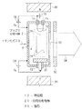
図1は、この発明に係るイオン源の一実施形態を示す概略断面図である。このイオン源は、アルミニウムイオンを含むイオンビーム34を発生させる(引き出す)イオン源であり、アーク放電の陽極を兼ねていて内部でプラズマ4を生成するためのプラズマ生成容器2を備えている。このプラズマ生成容器2は、例えば直方体状をしているが、この形状に限られるものではない。
FIG. 1 is a schematic sectional view showing an embodiment of an ion source according to the present invention. This ion source is an ion source that generates (extracts) an
プラズマ生成容器2内には、ガス導入口6を通して、フッ素を含むイオン化ガス8が導入される。ガス導入口6の位置は、図示例の位置に限定されるものではない。フッ素を含むイオン化ガス8を用いるのは、フッ素は化学作用が非常に強くて他の物質との反応性が強いので、フッ素を含むイオン化ガス8を電離させたプラズマ4によって、後述する対向反射電極20から、アルミニウムイオン等のアルミニウム粒子を放出させる作用が強いからである。
An ionized
フッ素を含むイオン化ガス8は、例えば、フッ化ホウ素(BF3 )、四フッ化ケイ素(SiF4 )、フッ化ゲルマニウム(GeF4 )等のフッ化物ガスまたはフッ素(F2 )を含むガスである。このフッ素を含むイオン化ガス8は、例えば、フッ化物ガスそのものまたはフッ素そのものでも良いし、それらを適当な希釈ガス(例えばヘリウムガス)で希釈したガスでも良い。
The ionized
プラズマ生成容器2内の一方側には、プラズマ生成容器2から電気的に絶縁して、プラズマ生成容器2内に熱電子を放出する熱陰極12が設けられている。
On one side of the
熱陰極12は、この実施形態のように直熱型のものでも良いし、後述する実施形態(図3等参照)のように傍熱型のものでも良い。
The
熱陰極12は、この実施形態では、U字状のフィラメントであり、絶縁物14によってプラズマ生成容器2から電気的に絶縁されている。なお、このフィラメントの向きは、加熱電源16との接続を明らかにするために便宜的に示したものであり、実際は、U字状に曲げたフィラメントを含む面が、後述するイオン引出し口10にほぼ平行になるように配置されている。図2に示す実施形態においても同様である。但し、フィラメントの形状はU字状以外でも良い。
In this embodiment, the
熱陰極12の両端には、当該熱陰極12を加熱する直流の加熱電源16が接続されている。熱陰極12の一端とプラズマ生成容器2との間には、両者12、2間にアーク電圧VA を印加して両者12、2間でアーク放電を生じさせて、プラズマ生成容器2内に導入されたイオン化ガス8を電離させてプラズマ4を生成するための直流のアーク電源18が、プラズマ生成容器2を正極側にして接続されている。
Both ends of the
プラズマ生成容器2内の他方側(熱陰極12とは反対側)に、熱陰極12に対向させて、プラズマ生成容器2内の電子(主として、熱陰極12から放出された熱電子。以下同様)を反射させる(換言すれば、跳ね返す、または追い返す。以下同様)機能を有する対向反射電極20が設けられている。この対向反射電極20は、絶縁物22によって、プラズマ生成容器2から電気的に絶縁されている。
Electrons in the plasma generation vessel 2 (mainly thermionic electrons emitted from the
対向反射電極20には、この実施形態では、直流のバイアス電源24から、プラズマ生成容器2の電位を基準にして負のバイアス電圧VB が印加される。バイアス電圧VB の大きさは、対向反射電極20によって電子を反射させる作用、対向反射電極20からアルミニウムイオン等のアルミニウム粒子を放出させる作用、プラズマ4中のイオンによって対向反射電極20の表面をスパッタする作用等の兼ね合いで決めれば良い。このような観点から、バイアス電圧VB の大きさは、例えば、40V〜150V程度が好ましい。その内でも、イオン化ガス8がフッ化ホウ素(BF3 )を含むガスである場合は、60V〜120V程度がより好ましい。
In this embodiment, a negative bias voltage V B is applied to the counter
公知のイオン源における対向反射電極は、チタン(Ti )、タンタル(Ta )、モリブデン(Mo )等の高融点金属またはそれらの合金から成るが、上記対向反射電極20は、アルミニウム含有物質から成る。アルミニウム含有物質は、例えば、酸化アルミニウム(Al2O3 )、窒化アルミニウム(AlN)等のアルミニウム化合物である。温度制御を行えば、アルミニウム(Al )を用いることもできる。
The counter-reflection electrode in the known ion source is made of a refractory metal such as titanium (Ti), tantalum (Ta), molybdenum (Mo), or an alloy thereof. The
プラズマ生成容器2の外部には、プラズマ生成容器2内に、熱陰極12と対向反射電極20とを結ぶ線26に沿う磁界28を発生させる磁石30が設けられている。磁石30は、例えば電磁石であるが、永久磁石でも良い。磁界28の向きは図示例とは逆向きでも良い。
A
上記のような対向反射電極20および磁界28の存在によって、プラズマ生成容器2内の電子は、磁界28の方向を軸として磁界28中で旋回しながら熱陰極12と対向反射電極20との間を往復運動するようになり、その結果、当該電子とイオン化ガス8のガス分子との衝突確率が高くなってイオン化ガス8の電離効率が高まるので、プラズマ4の生成効率が高まる。より具体的には、熱陰極12と対向反射電極20との間において密度の高いプラズマ4を生成することができる。
Due to the presence of the
プラズマ生成容器2の壁面には、プラズマ4からイオンを引き出すためのイオン引出し口10が設けられている。イオン引出し口10は、この実施形態では、上記線26に沿う方向に長い形状をしている。より具体的には、上記線26に沿う方向に長いスリット状をしている。但し、イオン引出し口10の形状はこれに限られるものではない。
An
イオン引出し口10の出口付近には、プラズマ生成容器2内から(より具体的にはそこに生成されるプラズマ4から)イオンビーム34を引き出す引出し電極系32が設けられている。引出し電極系32は、図示例では1枚の電極で構成されているが、それに限られるものではなく、複数枚の電極で構成されていても良い。
In the vicinity of the outlet of the
このイオン源においては、アルミニウム含有物質から成る対向反射電極20は、フッ素を含むイオン化ガス8を電離させて生成されたプラズマ4に曝される。そしてこのプラズマ4中のフッ素イオン、フッ素ラジカル等による浸食や、当該プラズマ4中のフッ素イオン等のイオンによるスパッタリング等によって、対向反射電極20から、アルミニウムイオン等のアルミニウム粒子がプラズマ4中に放出され、プラズマ4中にアルミニウムイオンが含まれるようになる。対向反射電極20から放出されるアルミニウム粒子には、アルミニウムイオンとして放出されるものもあるし、中性のアルミニウム原子として放出されるものもある。中性のアルミニウム原子も、ある程度の割合で、プラズマ4中の電子と衝突することによって電離されてアルミニウムイオンになる。このようにして、プラズマ4中にアルミニウムイオン(例えばAl+ 、Al2+ 、Al3+ 。以下同様)が含まれるようになる。その結果、当該アルミニウムイオンを含むイオンビーム34を発生させることができる。
In this ion source, the counter
このようにこのイオン源によれば、プラズマ生成容器2内の電子を反射させる機能を有する対向反射電極20からアルミニウムイオン等のアルミニウム粒子をプラズマ4中に放出させて、プラズマ4中にアルミニウムイオンを含ませることができるので、即ちプラズマ生成容器2内の電子を反射させる対向反射電極20をアルミニウム粒子放出用に兼用しているので、前述した従来例のイオン源のようにアルミニウムイオン生成専用のプレートを特別に設けなくて済む。従って、部品点数の削減および構造の簡素化が可能である。
As described above, according to this ion source, aluminum particles such as aluminum ions are discharged into the
しかも、熱陰極12と対向反射電極20とを結ぶ線26に沿う磁界28を発生させる磁石30を備えているので、前述したようにプラズマ生成容器2内の電子は熱陰極12と対向反射電極20との間を往復運動するようになり、熱陰極12と対向反射電極20との間において密度の高いプラズマ4を生成することができる。対向反射電極20は、そのような密度の高いプラズマ4の端部に位置しており、しかもプラズマ4は上記磁界28に沿う方向には移動しやすくその移動しやすい方向の端部に対向反射電極20が位置しているので、対向反射電極20は密度の高いプラズマ4に効率良く曝される。従って、対向反射電極20からアルミニウムイオン等のアルミニウム粒子を効率良くプラズマ4中に放出させることができる。その結果、イオンビーム34中に含まれるアルミニウムイオンの量を増大させることが容易になる。
In addition, since the
前述した従来例のイオン源では、アルミニウム含有物質のプレートは、イオン化室の底面に取り付けられている。このような位置のプレートよりも、上記対向反射電極20の方が上記磁界28との関係で密度の高いプラズマに効率良く曝されるので、より効率良く、アルミニウムイオン等のアルミニウム粒子をプラズマ4中に放出することができる。ひいては、アルミニウムイオンをより多量に含むイオンビーム34を発生させることができる。
In the above-described conventional ion source, the aluminum-containing material plate is attached to the bottom surface of the ionization chamber. Since the counter
なお、このイオン源の運転に伴って、即ちプラズマ4の生成に伴って、通常は、プラズマ4に曝される面に、対向反射電極20の表面も含めて、不要なパーティクルが堆積する。ここで対向反射電極20に着目すると、対向反射電極20はプラズマ生成容器2に対して負のバイアス電圧VB が印加されるので、上述した電子を反射させる作用に加えて、プラズマ4中のイオンをバイアス電圧VB で加速して引き込む作用をも奏する。この加速されたイオンによって、対向反射電極20の表面に堆積したパーティクルをスパッタして対向反射電極20の表面をクリーニングすることができるので、対向反射電極20の表面そのものを露出させてその表面からアルミニウム粒子を放出させる作用を、より長時間に亘って安定して維持することができる。
As the ion source is operated, that is, as the
これに対して、前述した従来例のイオン源では、アルミニウム含有物質のプレートに、イオン化室に対して負電圧を印加する(あるいは当該プレートを浮遊電位にする)ようには構成されていないので、当該プレートの表面に堆積したパーティクルを、加速されたイオンによってスパッタして当該プレートの表面をクリーニングする作用は期待できない。従って、当該プレートからアルミニウム粒子を放出させる機能は早く低下する。 On the other hand, the conventional ion source described above is not configured to apply a negative voltage to the ionization chamber (or to set the plate to a floating potential) to the aluminum-containing material plate. The effect of cleaning the surface of the plate by sputtering particles deposited on the surface of the plate with accelerated ions cannot be expected. Therefore, the function of releasing aluminum particles from the plate is quickly reduced.
対向反射電極20からアルミニウム粒子を放出させることによって対向反射電極20は消耗するので、必要に応じて対向反射電極20を交換すれば良い。この点は、前述した従来例のイオン源におけるプレートの場合と同様である。
Since the counter
ところで、このイオン源をイオン注入装置に用いて、炭化ケイ素基板等のターゲットにアルミニウムイオンを注入する場合は、必要に応じて、このイオン源とターゲットとの間に、イオンビーム34の運動量(例えば質量)分離を行って、必要な運動量のアルミニウムイオンを選別する質量分離器を設ければ良い。以下に述べる実施形態のイオン源を用いる場合も同様である。 By the way, when this ion source is used in an ion implantation apparatus and aluminum ions are implanted into a target such as a silicon carbide substrate, the momentum of the ion beam 34 (for example, between the ion source and the target, for example) Mass) separation may be performed to provide a mass separator that sorts out the necessary momentum of aluminum ions. The same applies to the case of using the ion source of the embodiment described below.
次に、この発明に係るイオン源の他の実施形態の幾つかを説明する。なお、以下の各実施形態の説明においては、それよりも先に説明した実施形態(例えば図1に示した実施形態)と同一または相当する部分には同一符号を付し、先に説明した実施形態との相違点を主体に説明する。 Next, some other embodiments of the ion source according to the present invention will be described. In the following description of each embodiment, the same or corresponding parts as those of the embodiment described earlier (for example, the embodiment shown in FIG. 1) are denoted by the same reference numerals, and the above-described embodiment is described. The difference from the form will be mainly described.
上記バイアス電源24を設ける代わりに、図2に示す実施形態のように、対向反射電極20を熱陰極12に接続して陰極電位に固定しても良い。より具体的には、対向反射電極20を、(a)図2に示す例のように加熱電源16の負極と熱陰極12の一端との接続部aに接続しても良いし、(b)加熱電源16の正極と熱陰極12の他端との接続部b(即ちアーク電源18の負極)に接続しても良い。いずれにしても、対向反射電極20に、プラズマ生成容器2の電位を基準にして負電圧を印加することができる。具体的には、上記(a)の場合はVA +VH の大きさの負電圧を、上記(b)の場合はVA の大きさの負電圧を、それぞれ印加することができる。VA は前述したアーク電源18の出力電圧であるアーク電圧、VH は加熱電源16の出力電圧である。アーク電圧VA の大きさは例えば40V〜120V程度、出力電圧VH の大きさは例えば2V〜4V程度である。
Instead of providing the
上記(a)の場合は、加熱電源16およびアーク電源18が、対向反射電極20に負電圧を印加する直流電源を兼ねており、上記(b)の場合は、アーク電源18が、対向反射電極20に負電圧を印加する直流電源を兼ねている。加熱電源16は交流電源でも良くその場合は、上記(b)を採用すれば良い。
In the case of (a), the
この実施形態の場合も、対向反射電極20に、プラズマ生成容器2を基準にして負電圧を印加することができるので、対向反射電極20に関して、図1に示した実施形態の場合とほぼ同様の作用効果を奏することができる。
Also in this embodiment, since a negative voltage can be applied to the counter
対向反射電極20に負電圧を印加する代わりに、対向反射電極20をどこにも電気的に接続せずに浮遊電位にしても良い。浮遊電位にしても、対向反射電極20にはプラズマ4中のイオンよりも軽くて移動度の高い電子がイオンよりも遥かに多く入射するので、対向反射電極20は負に帯電し、対向反射電極20に負電圧を印加した場合と同様の作用を奏することができる。即ち、対向反射電極20に関して、図1、図2に示した実施形態の場合とほぼ同様の作用効果を奏することができる。
Instead of applying a negative voltage to the counter
(a)図1に示した実施形態のようにバイアス電源24を設ける場合、(b)図2に示した実施形態のように対向反射電極20を熱陰極12に接続する場合、(c)対向反射電極20をどこにも接続せずに浮遊電位にする場合を比べると、(a)の場合は、バイアス電圧VB を自由に選べるので、対向反射電極20に、アルミニウムイオン発生等に最適な電圧を印加することが容易である。(b)の場合は、アーク電源18等が、対向反射電極20に負電圧を印加する電源を兼ねていて、対向反射電極20専用の電源が不要になるので、電源構成を簡素化することができる。しかも対向反射電極20の電位を固定することができる。(c)の場合は、対向反射電極20専用の電源が不要になるので、電源構成を簡素化することができる。これと同様のことは、後述する他の実施形態についても言える。
(A) When the
熱陰極12は、前述したように、傍熱型のものでも良い。その一例を図3に示す。
As described above, the
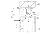
この熱陰極12は、加熱されることによって熱電子を放出する陰極部材36と、この陰極部材36を加熱するフィラメント38とを有している。なお、プラズマ生成容器2に対して陰極部材36およびフィラメント38を配置するより具体的な構造は、図3では簡略化して示しているが、例えば特許第3758667号公報等に記載されているような公知の構造を採用すれば良い。図5〜図7に示す実施形態においても同様である。
The
フィラメント38には、それを加熱する直流の加熱電源40が接続されている。フィラメント38と陰極部材36との間には、フィラメント38から放出された熱電子を陰極部材36に向けて加速して、当該熱電子の衝撃を利用して陰極部材36を加熱する直流のボンバード電源42が、陰極部材36を正極側にして接続されている。陰極部材36とプラズマ生成容器2との間には、前述したアーク電源18が接続されている。
A DC
この傍熱型の熱陰極12を設ける場合も、上記対向反射電極20には上記バイアス電圧VB を印加しても良いし、上記対向反射電極20を当該熱陰極12に接続して陰極電位に固定しても良い。より具体的には、対向反射電極20を、(a)加熱電源40の負極とフィラメント38の一端との接続部cに接続しても良いし、(b)加熱電源40の正極とフィラメント38の他端との接続部dに接続しても良いし、(c)図3中に二点鎖線で示すように、陰極部材36とアーク電源18との接続部e(即ちアーク電源18の負極)に接続しても良い。いずれにしても、対向反射電極20に、プラズマ生成容器2の電位を基準にして負電圧を印加することができる。具体的には、上記(a)の場合はVA +VD +VF の大きさの負電圧を、上記(b)の場合はVA +VD の大きさの負電圧を、上記(c)の場合はVA の大きさの負電圧を、それぞれ印加することができる。VA は前述したアーク電圧、VD はボンバード電源42の出力電圧、VF は加熱電源40の出力電圧である。アーク電圧VA の大きさは前述したように例えば40V〜120V程度、出力電圧VF の大きさは例えば2V〜4V程度、出力電圧VD の大きさは例えば300V〜600V程度である。
Even when the indirectly heated
上記(a)の場合は、アーク電源18、ボンバード電源42および加熱電源40が、対向反射電極20に負電圧を印加する直流電源を兼ねており、上記(b)の場合は、アーク電源18およびボンバード電源42が、対向反射電極20に負電圧を印加する直流電源を兼ねており、上記(c)の場合は、アーク電源18が、対向反射電極20に負電圧を印加する直流電源を兼ねている。加熱電源40は交流電源でも良くその場合は、上記(b)または(c)を採用すれば良い。
In the case of (a), the
ところで、イオン源には、例えば特許第3797160号公報にも記載されているように、対向反射電極に加えて、熱陰極側にも反射電極(背後反射電極)を備えているものもある。但し、公知のイオン源における両反射電極は、前述したように高融点金属またはその合金から成り、アルミニウム含有物質から成るものではない。この背後反射電極に相当する背後反射電極を更に備えているイオン源の実施形態を図4に示す。 Incidentally, as described in, for example, Japanese Patent No. 3797160, some ion sources include a reflective electrode (back reflective electrode) on the hot cathode side in addition to the counter reflective electrode. However, both the reflection electrodes in the known ion source are made of a refractory metal or an alloy thereof as described above, and are not made of an aluminum-containing material. FIG. 4 shows an embodiment of an ion source further including a back reflecting electrode corresponding to the back reflecting electrode.
この実施形態のイオン源は、プラズマ生成容器2内であって熱陰極12の電子放出部の背後に、対向反射電極20に対向させて、かつプラズマ生成容器2から電気的に絶縁して設けられていて、プラズマ生成容器2の電位を基準にして負電圧が印加される(または後述するように浮遊電位にされる)電極であって、プラズマ生成容器2内の電子を反射させる機能を有している背後反射電極44を更に備えている。そしてこの背後反射電極44を、前述したようなアルミニウム含有物質で構成している。
The ion source of this embodiment is provided in the
背後反射電極44をプラズマ生成容器2内にプラズマ生成容器2から電気的に絶縁して支持する手段には、公知のものが採用できる。この実施形態では一例として、電流導入端子を兼ねる絶縁物48で支持しているが、これに限られるものではない。図5に示す実施形態では、背後反射電極44の上記支持手段の図示を省略している。
As the means for supporting the
熱陰極12の電子放出部というのは、熱陰極12の内でも特に多くの熱電子を放出する部分のことであり、具体的には熱陰極12の先端部分(プラズマ生成容器2内側の先端部分)のことである。図5に示す傍熱型の熱陰極12の場合は、その陰極部材36の先端部分(プラズマ生成容器2内側の先端部分)のことである。
The electron emission portion of the
背後反射電極44は、この実施形態では、熱陰極12(より具体的にはその脚部)を電気的に絶縁して通す穴46を有している。熱陰極12と背後反射電極44との間には、例えば3mm程度の間隔がある。従って、背後反射電極44は熱陰極12の近傍に設けられていると言うことができる。
In this embodiment, the
背後反射電極44には、(a)図4に示す例のように、上記バイアス電源24を対向反射電極20と共用して当該バイアス電源24からプラズマ生成容器2の電位を基準にして負のバイアス電圧VB を印加しても良いし、(b)バイアス電源24とは別の直流のバイアス電源によってプラズマ生成容器2の電位を基準にして負のバイアス電圧を印加しても良いし、(c)図2に示した対向反射電極20の場合と同様に、背後反射電極44を上記接続部aまたはbに接続することによって、背後反射電極44にプラズマ生成容器2の電位を基準にして負電圧を印加するようにしても良い。
As shown in FIG. 4, the
あるいは、背後反射電極44に負電圧を印加する代わりに、背後反射電極44をどこにも電気的に接続せずに浮遊電位にしても良い。浮遊電位にしても、前述した浮遊電位の対向反射電極20の場合と同様に、背後反射電極44にはプラズマ4中のイオンよりも軽くて移動度の高い電子がイオンよりも遥かに多く入射するので、背後反射電極44は負に帯電し、背後反射電極44に負電圧を印加した場合と同様の作用を奏することができる。
Alternatively, instead of applying a negative voltage to the
即ち、背後反射電極44は、上記対向反射電極20の場合と同様に、プラズマ生成容器2内の電子を反射させる作用を奏する。
That is, the
しかも、この背後反射電極44も、当該イオン源の運転中は、フッ素を含むイオン化ガス8を電離させて生成されたプラズマ4に曝されるので、しかもこの背後反射電極44もアルミニウム含有物質から成るので、対向反射電極20について上述したのと同様の作用によって、即ちプラズマ4中のフッ素イオン、フッ素ラジカル等による浸食や、プラズマ4中のフッ素イオン等のイオンによるスパッタリング等によって、背後反射電極44からもアルミニウム粒子がプラズマ4中に放出されるようになる。つまり、対向反射電極20だけをアルミニウム含有物質で構成する場合よりも、プラズマ4中のフッ素イオン等による浸食やスパッタリングを受けるアルミニウム含有物質の面積を増やすことができる。従って、プラズマ4中に放出されるアルミニウム粒子の量を増大させて、イオンビーム34中に含まれるアルミニウムイオンの量を、即ちアルミニウムイオンビームの量を増大させることができる。
Moreover, since the
また、背後反射電極44は、前述したように熱陰極12が近傍に設けられていてそれからの放射熱によって高温になる結果、スパッタ率の向上およびアルミニウム含有物質の蒸気圧の上昇が期待でき、それによってプラズマ4中に放出されるアルミニウム粒子の量が増大するので、この観点からもイオンビーム34中に含まれるアルミニウムイオンの量を増大させることができる。
Further, as described above, the
高温になると背後反射電極44のスパッタ率の向上が期待できるのは、簡単に言えば、背後反射電極44を構成するアルミニウム含有物質を構成しているアルミニウム原子や他の原子等の格子振動が高温になると活発になり、これらの原子等の化学結合が切れやすくなって、アルミニウム粒子が飛び出しやすくなるからである。
Simply speaking, the sputtering rate of the
高温になるとアルミニウム含有物質の蒸気圧の上昇が期待できると言っているのは、背後反射電極44を構成するアルミニウム含有物質から前記作用によって放出されるアルミニウム粒子は厳密には蒸気とは言えないかも知れないけれども、高温になると蒸気圧が高まるのに似た現象によって、アルミニウム含有物質からアルミニウム粒子が雰囲気中(即ちプラズマ生成容器2内の真空雰囲気中)へ放出されやすくなるので、これを蒸気の場合と同様に蒸気圧の上昇と言っているのである。
The reason why the vapor pressure of the aluminum-containing material can be expected to increase at a high temperature is that the aluminum particles released from the aluminum-containing material constituting the
しかもこの実施形態の場合も、プラズマ生成容器2内の電子を反射させる機能を有する背後反射電極44をアルミニウム粒子放出用に兼用しているので、従来のイオン源のようにアルミニウムイオン生成専用のプレートを特別に設けなくて済み、それを特別に設ける場合に比べて部品点数の削減および構造の簡素化が可能である。
Moreover, also in this embodiment, the
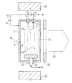
対向反射電極20に加えて上記のような背後反射電極44を備えており、かつ熱陰極12が傍熱型の場合の実施形態を図5に示す。
FIG. 5 shows an embodiment in which the
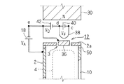
この熱陰極12は、図3に示した熱陰極12とほぼ同じ構造をしているが、この実施形態では、陰極部材36はプラズマ生成容器2内に配置されている。そしてこの熱陰極12の電子放出部(即ち前述したように陰極部材36の先端部分)の背後に、上記対向反射電極20(図4等参照)に対向させて、かつプラズマ生成容器2から電気的に絶縁して上記背後反射電極44を設けている。背後反射電極44は、言い方を変えれば陰極部材36の先端部分の側方後方に設けられていると言うこともできるが、それもこの明細書では上記「背後」に含めている。
The
背後反射電極44は、この実施形態では、陰極部材36を電気的に絶縁して通す穴46を有している。陰極部材36と背後反射電極44との間には、例えば3mm程度の間隔がある。従ってこの背後反射電極44も、熱陰極12の、より具体的にはその陰極部材36の近傍に設けられていると言うことができる。
In this embodiment, the
この実施形態における背後反射電極44にも、図4に示した実施形態の場合とほぼ同様にして、プラズマ生成容器2の電位を基準にして負電圧を印加しても良いし、背後反射電極44をどこにも電気的に接続せずに浮遊電位にしても良い。負電圧を印加する場合は、(a)上記バイアス電源24から負のバイアス電圧VB を印加しても良いし、(b)バイアス電源24とは別の直流のバイアス電源から負のバイアス電圧を印加しても良いし、(c)図3に示した実施形態の場合と同様に背後反射電極44を上記接続部e、dまたはcに接続しても良い。もっとも、背後反射電極44が図4の実施形態で説明した作用と同様の作用を奏するためには、背後反射電極44に上記出力電圧VD が含まれているほどの大きな負電圧を印加する必要はないので、背後反射電極44を接続部eに接続してそれに上記アーク電圧VA を印加すれば大きさとしては十分である。
A negative voltage may be applied to the
この実施形態の場合も、背後反射電極44に関して、図4の実施形態について説明したのとほぼ同様の作用効果を奏することができる。即ち、プラズマ生成容器2内の電子を反射させる作用に加えて、プラズマ4中に放出されるアルミニウム粒子の量を増大させてイオンビーム34(図4参照)中に含まれるアルミニウムイオンの量を増大させることができる。熱陰極12が近傍にあるために背後反射電極44が高温になり、プラズマ4中に放出されるアルミニウム粒子の量が増大することも前記と同様である。また、背後反射電極44をアルミニウム粒子放出用に兼用しているので、部品点数の削減および構造の簡素化が可能である。
Also in the case of this embodiment, with respect to the
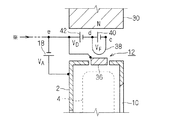
図6に示す実施形態では、上記熱陰極12の陰極部材36は、プラズマ生成容器2の開口部3内に配置されている。そしてこのプラズマ生成容器2の上記開口部3を含んでいる壁面2a(より具体的には開口部3を含んでいる一つの側面)を、電気絶縁性のアルミニウム含有物質で構成している。電気絶縁性のアルミニウム含有物質は、例えば、前述した酸化アルミニウム(Al2O3 )、窒化アルミニウム(AlN)等のアルミニウム化合物である。
In the embodiment shown in FIG. 6, the
上記アルミニウム含有物質で構成された壁面2aは、電気絶縁性のものであるので、浮遊電位にある。この壁面2aには、前述した浮遊電位の背後反射電極44の場合と同様に、イオン源運転中はプラズマ4中のイオンよりも軽くて移動度の高い電子がイオンよりも遥かに多く入射するので、当該壁面2aは負に帯電する。
Since the
従ってこの壁面2aも、上記背後反射電極44の場合と同様に、プラズマ生成容器2内の電子を反射させる作用を奏する。それに加えて、プラズマ4中に放出されるアルミニウム粒子の量を増大させてイオンビーム34中に含まれるアルミニウムイオンの量を増大させる作用効果も奏するが、これについては図7に示す実施形態と共に説明する。
Accordingly, the
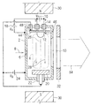
図7に示す実施形態では、プラズマ生成容器2の上記開口部3を含んでいる壁面2aを、アルミニウム含有物質で構成し、かつ絶縁物50を介在させてプラズマ生成容器2の他の壁面から電気的に絶縁している。この実施形態では、アルミニウム含有物質は電気絶縁性でも良いし導電性でも良い。
In the embodiment shown in FIG. 7, the
上記アルミニウム含有物質で構成された壁面2aには、図5に示した実施形態における背後反射電極44の場合とほぼ同様にして、プラズマ生成容器2の電位を基準にして負電圧を印加しても良いし、当該壁面2aをどこにも電気的に接続せずに浮遊電位にしても良い。負電圧を印加する場合は、(a)上記バイアス電源24から負のバイアス電圧VB を印加しても良いし、(b)バイアス電源24とは別の直流のバイアス電源から負のバイアス電圧を印加しても良いし、(c)上記壁面2aを上記接続部e、dまたはcに接続しても良い。例えば前記と同様の理由から接続部eに接続すれば良い。
Even if a negative voltage is applied to the
上記壁面2aを浮遊電位にしても、図6に示した実施形態における壁面2aの場合と同様の作用によって上記壁面2aは負に帯電するので、上記壁面2aに負電圧を印加した場合と同様の作用効果を奏することができる。
Even if the
即ち、上記壁面2aは、上記背後反射電極44等の場合と同様に、プラズマ生成容器2内の電子を反射させる作用を奏する。
That is, the
しかも、図6、図7に示したいずれの実施形態の場合も、上記アルミニウム含有物質で構成された壁面2aは、イオン源の運転中は、フッ素を含むイオン化ガス8を電離させて生成されたプラズマ4に曝されるので、対向反射電極20や背後反射電極44について上述したのと同様の作用によって、即ちプラズマ4中のフッ素イオン、フッ素ラジカル等による浸食や、プラズマ4中のフッ素イオン等のイオンによるスパッタリング等によって、上記アルミニウム含有物質で構成された壁面2aからもアルミニウム粒子がプラズマ4中に放出されるようになる。つまり、対向反射電極20だけをアルミニウム含有物質で構成する場合よりも、プラズマ4中のフッ素イオン等による浸食やスパッタリングを受けるアルミニウム含有物質の面積を増やすことができる。従って、プラズマ4中に放出されるアルミニウム粒子の量を増大させて、イオンビーム34中に含まれるアルミニウムイオンの量を、即ちアルミニウムイオンビームの量を増大させることができる。
Moreover, in any of the embodiments shown in FIGS. 6 and 7, the
また、上記アルミニウム含有物質で構成された壁面2aも、熱陰極12が(具体的にはその陰極部材36等が)近傍にあってそれからの放射熱によって高温になる結果、前記背後反射電極44の場合と同様に、当該壁面2aのスパッタ率の向上およびアルミニウム含有物質の蒸気圧の上昇が期待でき、それによってプラズマ4中に放出されるアルミニウム粒子の量が増大するので、この観点からもイオンビーム34中に含まれるアルミニウムイオンの量を増大させることができる。
Further, the
しかも図6、図7いずれの実施形態の場合も、プラズマ生成容器2を構成する壁面の内の一部の壁面を、即ち上記開口部3を含んでいる壁面2aを、アルミニウム粒子放出用に兼用しているので、従来のイオン源のようにアルミニウムイオン生成専用のプレートを特別に設けなくて済み、それを特別に設ける場合に比べて部品点数の削減および構造の簡素化が可能である。
Moreover, in both the embodiments of FIGS. 6 and 7, a part of the wall surfaces constituting the
図6、図7の両実施形態を比べると、絶縁物50が不要であるので図6の実施形態の方がより構造が簡単であり、逆に絶縁物50を有している分、図7の実施形態の方が上記壁面2aとプラズマ生成容器2の他の壁面との間の電気絶縁を確実に取ることが容易になる。
6 and 7, since the
なお、プラズマ生成容器2内側の絶縁物50の表面に、例えば溝を設ける等によって、沿面距離を増大させる構造を採用しても良く、そのようにすれば絶縁物50の表面の汚れによって絶縁性能が低下するのを抑制することができる。
In addition, you may employ | adopt the structure which increases a creepage distance by providing a groove | channel etc. in the surface of the
2 プラズマ生成容器
2a アルミニウム含有物質で構成された壁面
4 プラズマ
8 イオン化ガス
12 熱陰極
20 対向反射電極
24 バイアス電源
28 磁界
30 磁石
34 イオンビーム
36 陰極部材
44 背後反射電極
DESCRIPTION OF
Claims (7)
陽極を兼ねていて内部でプラズマを生成するための容器であって、フッ素を含むイオン化ガスが導入されるプラズマ生成容器と、
前記プラズマ生成容器内の一方側に、前記プラズマ生成容器から電気的に絶縁して設けられた熱陰極と、
前記プラズマ生成容器内の他方側に、前記プラズマ生成容器から電気的に絶縁して、かつ前記熱陰極に対向させて設けられていて、前記プラズマ生成容器の電位を基準にして負電圧が印加される電極であって、前記プラズマ生成容器内の電子を反射させる機能を有しており、かつアルミニウム含有物質から成る対向反射電極と、
前記プラズマ生成容器内に、前記熱陰極と前記対向反射電極とを結ぶ線に沿う磁界を発生させる磁石とを備えていることを特徴とするイオン源。 An ion source for generating an ion beam containing aluminum ions,
A container that also serves as an anode and generates plasma therein, and a plasma generation container into which an ionized gas containing fluorine is introduced;
A hot cathode provided on one side of the plasma generation vessel in electrical insulation from the plasma generation vessel;
The other side of the plasma generation vessel is provided so as to be electrically insulated from the plasma generation vessel and opposed to the hot cathode, and a negative voltage is applied with reference to the potential of the plasma generation vessel. An electrode having a function of reflecting electrons in the plasma generation container and made of an aluminum-containing material,
An ion source comprising: a magnet for generating a magnetic field along a line connecting the hot cathode and the counter-reflection electrode in the plasma generation container.
陽極を兼ねていて内部でプラズマを生成するための容器であって、フッ素を含むイオン化ガスが導入されるプラズマ生成容器と、
前記プラズマ生成容器内の一方側に、前記プラズマ生成容器から電気的に絶縁して設けられた熱陰極と、
前記プラズマ生成容器内の他方側に、前記プラズマ生成容器から電気的に絶縁して、かつ前記熱陰極に対向させて設けられた浮遊電位の電極であって、前記プラズマ生成容器内の電子を反射させる機能を有しており、かつアルミニウム含有物質から成る対向反射電極と、
前記プラズマ生成容器内に、前記熱陰極と前記対向反射電極とを結ぶ線に沿う磁界を発生させる磁石とを備えていることを特徴とするイオン源。 An ion source for generating an ion beam containing aluminum ions,
A container that also serves as an anode and generates plasma therein, and a plasma generation container into which an ionized gas containing fluorine is introduced;
A hot cathode provided on one side of the plasma generation vessel in electrical insulation from the plasma generation vessel;
A floating potential electrode provided on the other side of the plasma generation container so as to be electrically insulated from the plasma generation container and opposed to the hot cathode, and reflects electrons in the plasma generation container A counter-reflection electrode made of an aluminum-containing material,
An ion source comprising: a magnet for generating a magnetic field along a line connecting the hot cathode and the counter-reflection electrode in the plasma generation container.
前記プラズマ生成容器の前記開口部を含んでいる壁面を、電気絶縁性のアルミニウム含有物質で構成している請求項1または2記載のイオン源。 The hot cathode is a indirectly heated hot cathode having a cathode member that emits thermoelectrons when heated and a filament that heats the cathode member. Located in the opening,
The ion source according to claim 1 or 2, wherein a wall surface including the opening of the plasma generation container is made of an electrically insulating aluminum-containing material.
前記プラズマ生成容器の前記開口部を含んでいる壁面を、アルミニウム含有物質で構成し、かつ絶縁物を介在させて前記プラズマ生成容器の他の壁面から電気的に絶縁して浮遊電位にしている請求項1または2記載のイオン源。 The hot cathode is a indirectly heated hot cathode having a cathode member that emits thermoelectrons when heated and a filament that heats the cathode member. Located in the opening,
The wall surface including the opening of the plasma generation vessel is made of an aluminum-containing material, and is electrically insulated from other wall surfaces of the plasma generation vessel with an insulating material interposed therebetween to have a floating potential. Item 3. The ion source according to Item 1 or 2.
前記プラズマ生成容器の前記開口部を含んでいる壁面を、アルミニウム含有物質で構成し、かつ絶縁物を介在させて前記プラズマ生成容器の他の壁面から電気的に絶縁しており、
かつ前記アルミニウム含有物質で構成された壁面には前記プラズマ生成容器の電位を基準にして負電圧が印加される請求項1または2記載のイオン源。 The hot cathode is a indirectly heated hot cathode having a cathode member that emits thermoelectrons when heated and a filament that heats the cathode member. Located in the opening,
The wall including the opening of the plasma generation vessel is made of an aluminum-containing material, and is electrically insulated from other wall surfaces of the plasma generation vessel via an insulator,
The ion source according to claim 1, wherein a negative voltage is applied to the wall surface made of the aluminum-containing substance with reference to the potential of the plasma generation container.
Priority Applications (3)
| Application Number | Priority Date | Filing Date | Title |
|---|---|---|---|
| JP2009122675A JP4428467B1 (en) | 2008-08-27 | 2009-05-21 | Ion source |
| CN2009101520445A CN101661862B (en) | 2008-08-27 | 2009-07-15 | Ion source |
| US12/547,176 US8253114B2 (en) | 2008-08-27 | 2009-08-25 | Ion source |
Applications Claiming Priority (2)
| Application Number | Priority Date | Filing Date | Title |
|---|---|---|---|
| JP2008218090 | 2008-08-27 | ||
| JP2009122675A JP4428467B1 (en) | 2008-08-27 | 2009-05-21 | Ion source |
Publications (2)
| Publication Number | Publication Date |
|---|---|
| JP4428467B1 JP4428467B1 (en) | 2010-03-10 |
| JP2010080429A true JP2010080429A (en) | 2010-04-08 |
Family
ID=41723909
Family Applications (1)
| Application Number | Title | Priority Date | Filing Date |
|---|---|---|---|
| JP2009122675A Active JP4428467B1 (en) | 2008-08-27 | 2009-05-21 | Ion source |
Country Status (3)
| Country | Link |
|---|---|
| US (1) | US8253114B2 (en) |
| JP (1) | JP4428467B1 (en) |
| CN (1) | CN101661862B (en) |
Cited By (6)
| Publication number | Priority date | Publication date | Assignee | Title |
|---|---|---|---|---|
| JP2012221629A (en) * | 2011-04-05 | 2012-11-12 | Nissin Ion Equipment Co Ltd | Ion source and reflective electrode structure |
| KR20190014107A (en) * | 2016-06-30 | 2019-02-11 | 베리안 세미콘덕터 이큅먼트 어소시에이츠, 인크. | Ion source for improved ionization |
| WO2019077970A1 (en) * | 2017-10-18 | 2019-04-25 | 株式会社アルバック | Ion source and ion injection device |
| JP2020173984A (en) * | 2019-04-11 | 2020-10-22 | 株式会社アルバック | Ion source, ion implanter, and magnesium ion generation method |
| US11107659B2 (en) | 2019-07-16 | 2021-08-31 | Sumitomo Heavy Industries Ion Technology Co., Ltd. | Ion generator and ion implanter |
| US11232925B2 (en) | 2019-09-03 | 2022-01-25 | Applied Materials, Inc. | System and method for improved beam current from an ion source |
Families Citing this family (31)
| Publication number | Priority date | Publication date | Assignee | Title |
|---|---|---|---|---|
| JP2983010B2 (en) | 1997-11-13 | 1999-11-29 | 株式会社 トーア | Manufacturing method of non-washed rice |
| JP5040723B2 (en) * | 2008-02-26 | 2012-10-03 | 日新イオン機器株式会社 | Ion source |
| JP2009295475A (en) * | 2008-06-06 | 2009-12-17 | Nissin Ion Equipment Co Ltd | Ion injecting device and beam orbit correction method |
| JP5343835B2 (en) * | 2009-12-10 | 2013-11-13 | 日新イオン機器株式会社 | Reflective electrode structure and ion source |
| WO2011156499A1 (en) * | 2010-06-08 | 2011-12-15 | Ionwerks, Inc. | Nanoparticulate assisted nanoscale molecular imaging by mass spectrometery |
| US8450701B2 (en) * | 2011-04-19 | 2013-05-28 | Axcelis Technologies, Inc. | Vacuum system cold trap filter |
| CN102789945A (en) * | 2011-05-17 | 2012-11-21 | 上海凯世通半导体有限公司 | Hot-cathode ion source system for generating strip-shaped beam |
| JP5822767B2 (en) * | 2012-03-22 | 2015-11-24 | 住友重機械イオンテクノロジー株式会社 | Ion source apparatus and ion beam generating method |
| US9520263B2 (en) | 2013-02-11 | 2016-12-13 | Novaray Medical Inc. | Method and apparatus for generation of a uniform-profile particle beam |
| US9502213B2 (en) | 2013-03-15 | 2016-11-22 | Nissin Ion Equipment Co., Ltd. | Ion beam line |
| US9142386B2 (en) | 2013-03-15 | 2015-09-22 | Nissin Ion Equipment Co., Ltd. | Ion beam line |
| WO2016046939A1 (en) * | 2014-09-25 | 2016-03-31 | 三菱電機株式会社 | Ion implantation apparatus |
| CN104480447A (en) * | 2014-12-31 | 2015-04-01 | 北京中科信电子装备有限公司 | Multifunctional ion source |
| CN105390355B (en) * | 2015-11-20 | 2018-01-16 | 中国电子科技集团公司第四十八研究所 | A kind of reflective electrode structure part and ion gun |
| CN105448630A (en) * | 2015-12-11 | 2016-03-30 | 中国电子科技集团公司第四十八研究所 | Ion source for generating aluminum ion beam |
| CN105575748B (en) * | 2015-12-11 | 2017-11-21 | 中国电子科技集团公司第四十八研究所 | A kind of method for improving heavy caliber ion gun ion beam current uniformity |
| CN105655217B (en) * | 2015-12-14 | 2017-12-15 | 中国电子科技集团公司第四十八研究所 | A kind of magnetron sputtering metal source of aluminum ion of rf bias power supply |
| US9824846B2 (en) * | 2016-01-27 | 2017-11-21 | Varian Semiconductor Equipment Associates, Inc. | Dual material repeller |
| JP6455494B2 (en) * | 2016-09-15 | 2019-01-23 | 日新イオン機器株式会社 | Ion source |
| WO2018185987A1 (en) * | 2017-04-06 | 2018-10-11 | 株式会社アルバック | Ion source and ion implanter |
| TWI818252B (en) * | 2017-06-05 | 2023-10-11 | 美商瓦里安半導體設備公司 | Indirectly heated cathode ion source |
| CN108172490B (en) * | 2017-12-26 | 2020-01-03 | 广州今泰科技股份有限公司 | Multipurpose filament gas ion source device |
| CN108551716A (en) * | 2018-07-06 | 2018-09-18 | 中国科学技术大学 | A kind of plasma generating apparatus |
| US11120966B2 (en) | 2019-09-03 | 2021-09-14 | Applied Materials, Inc. | System and method for improved beam current from an ion source |
| US10854416B1 (en) * | 2019-09-10 | 2020-12-01 | Applied Materials, Inc. | Thermally isolated repeller and electrodes |
| US11127558B1 (en) | 2020-03-23 | 2021-09-21 | Applied Materials, Inc. | Thermally isolated captive features for ion implantation systems |
| KR20230075502A (en) | 2020-10-02 | 2023-05-31 | 엔테그리스, 아이엔씨. | Methods and systems useful for generating aluminum ions |
| US11699563B2 (en) * | 2020-10-30 | 2023-07-11 | Axcelis Technologies, Inc. | Etching aluminum nitride or aluminum oxide to generate an aluminum ion beam |
| CN113482870B (en) * | 2021-08-19 | 2022-06-03 | 北京理工大学 | Carbon nanotube gas field ionization thruster with double-gate structure |
| US20230082224A1 (en) * | 2021-09-13 | 2023-03-16 | Applied Materials, Inc. | Device To Control Uniformity Of Extraction Ion Beam |
| CN114242549B (en) * | 2021-12-21 | 2024-02-20 | 北京凯世通半导体有限公司 | Ion source device for forming plasma by material sputtering |
Citations (3)
| Publication number | Priority date | Publication date | Assignee | Title |
|---|---|---|---|---|
| JPH11238485A (en) * | 1998-02-24 | 1999-08-31 | Sony Corp | Ion implanting method |
| JP3758667B1 (en) * | 2005-05-17 | 2006-03-22 | 日新イオン機器株式会社 | Ion source |
| JP3793160B2 (en) * | 2003-02-28 | 2006-07-05 | 蒲田製氷冷蔵株式会社 | Automatic ice charging device for food passers |
Family Cites Families (19)
| Publication number | Priority date | Publication date | Assignee | Title |
|---|---|---|---|---|
| US4424104A (en) * | 1983-05-12 | 1984-01-03 | International Business Machines Corporation | Single axis combined ion and vapor source |
| JPH07112539B2 (en) * | 1992-04-15 | 1995-12-06 | 工業技術院長 | Method and apparatus for producing fine particles |
| US6653626B2 (en) * | 1994-07-11 | 2003-11-25 | Agilent Technologies, Inc. | Ion sampling for APPI mass spectrometry |
| US6239440B1 (en) * | 1996-03-27 | 2001-05-29 | Thermoceramix, L.L.C. | Arc chamber for an ion implantation system |
| US7838842B2 (en) * | 1999-12-13 | 2010-11-23 | Semequip, Inc. | Dual mode ion source for ion implantation |
| US6777686B2 (en) * | 2000-05-17 | 2004-08-17 | Varian Semiconductor Equipment Associates, Inc. | Control system for indirectly heated cathode ion source |
| US6661014B2 (en) * | 2001-03-13 | 2003-12-09 | Varian Semiconductor Equipment Associates, Inc. | Methods and apparatus for oxygen implantation |
| GB0128913D0 (en) * | 2001-12-03 | 2002-01-23 | Applied Materials Inc | Improvements in ion sources for ion implantation apparatus |
| JP2004134354A (en) * | 2002-08-13 | 2004-04-30 | Nissin Electric Co Ltd | Thermoelectron generating source and ion beam irradiation device equipped with it |
| US7724492B2 (en) * | 2003-09-05 | 2010-05-25 | Tessera, Inc. | Emitter electrode having a strip shape |
| GB2407433B (en) * | 2003-10-24 | 2008-12-24 | Applied Materials Inc | Cathode and counter-cathode arrangement in an ion source |
| US20080223409A1 (en) * | 2003-12-12 | 2008-09-18 | Horsky Thomas N | Method and apparatus for extending equipment uptime in ion implantation |
| JP4643588B2 (en) * | 2003-12-12 | 2011-03-02 | セメクイップ, インコーポレイテッド | Control of vapor flow sublimated from solids |
| US7791047B2 (en) * | 2003-12-12 | 2010-09-07 | Semequip, Inc. | Method and apparatus for extracting ions from an ion source for use in ion implantation |
| JP4179337B2 (en) * | 2006-05-17 | 2008-11-12 | 日新イオン機器株式会社 | Ion source and operation method thereof |
| US7435971B2 (en) * | 2006-05-19 | 2008-10-14 | Axcelis Technologies, Inc. | Ion source |
| JP4915671B2 (en) * | 2007-09-20 | 2012-04-11 | 日新イオン機器株式会社 | Ion source, ion implantation apparatus, and ion implantation method |
| JP4548523B2 (en) * | 2008-07-18 | 2010-09-22 | 日新イオン機器株式会社 | Assembly method for indirectly heated cathode |
| JP5119396B2 (en) * | 2008-08-18 | 2013-01-16 | 日新イオン機器株式会社 | Hot cathode and ion source comprising the same |
-
2009
- 2009-05-21 JP JP2009122675A patent/JP4428467B1/en active Active
- 2009-07-15 CN CN2009101520445A patent/CN101661862B/en not_active Expired - Fee Related
- 2009-08-25 US US12/547,176 patent/US8253114B2/en active Active
Patent Citations (3)
| Publication number | Priority date | Publication date | Assignee | Title |
|---|---|---|---|---|
| JPH11238485A (en) * | 1998-02-24 | 1999-08-31 | Sony Corp | Ion implanting method |
| JP3793160B2 (en) * | 2003-02-28 | 2006-07-05 | 蒲田製氷冷蔵株式会社 | Automatic ice charging device for food passers |
| JP3758667B1 (en) * | 2005-05-17 | 2006-03-22 | 日新イオン機器株式会社 | Ion source |
Cited By (10)
| Publication number | Priority date | Publication date | Assignee | Title |
|---|---|---|---|---|
| JP2012221629A (en) * | 2011-04-05 | 2012-11-12 | Nissin Ion Equipment Co Ltd | Ion source and reflective electrode structure |
| KR20190014107A (en) * | 2016-06-30 | 2019-02-11 | 베리안 세미콘덕터 이큅먼트 어소시에이츠, 인크. | Ion source for improved ionization |
| KR102198551B1 (en) | 2016-06-30 | 2021-01-06 | 베리안 세미콘덕터 이큅먼트 어소시에이츠, 인크. | Indirect heated ion source and Bernas ion source |
| KR20210005291A (en) * | 2016-06-30 | 2021-01-13 | 베리안 세미콘덕터 이큅먼트 어소시에이츠, 인크. | Indirectly heated cathode ion source and bernas ion source |
| KR102332684B1 (en) | 2016-06-30 | 2021-12-02 | 베리안 세미콘덕터 이큅먼트 어소시에이츠, 인크. | Indirectly heated cathode ion source and bernas ion source |
| WO2019077970A1 (en) * | 2017-10-18 | 2019-04-25 | 株式会社アルバック | Ion source and ion injection device |
| JP6514425B1 (en) * | 2017-10-18 | 2019-05-15 | 株式会社アルバック | Ion source and ion implanter |
| JP2020173984A (en) * | 2019-04-11 | 2020-10-22 | 株式会社アルバック | Ion source, ion implanter, and magnesium ion generation method |
| US11107659B2 (en) | 2019-07-16 | 2021-08-31 | Sumitomo Heavy Industries Ion Technology Co., Ltd. | Ion generator and ion implanter |
| US11232925B2 (en) | 2019-09-03 | 2022-01-25 | Applied Materials, Inc. | System and method for improved beam current from an ion source |
Also Published As
| Publication number | Publication date |
|---|---|
| CN101661862A (en) | 2010-03-03 |
| US8253114B2 (en) | 2012-08-28 |
| JP4428467B1 (en) | 2010-03-10 |
| US20100051825A1 (en) | 2010-03-04 |
| CN101661862B (en) | 2011-06-15 |
Similar Documents
| Publication | Publication Date | Title |
|---|---|---|
| JP4428467B1 (en) | Ion source | |
| EP2492949B1 (en) | Stable cold field emission electron source | |
| CN102097271B (en) | Repeller structure and ion source | |
| JP4179337B2 (en) | Ion source and operation method thereof | |
| KR102272680B1 (en) | Ion generating device and thermoelectron emitter | |
| TWI671778B (en) | Ion beam device, ion implantation device, ion beam irradiation method | |
| JP3716700B2 (en) | Ion source and operation method thereof | |
| TWI730642B (en) | Indirectly heated cathode ion source and method of operating the same | |
| CN105655217A (en) | Magnetron sputtering metal aluminum ion source of radio frequency bias voltage power supply | |
| US7622721B2 (en) | Focused anode layer ion source with converging and charge compensated beam (falcon) | |
| CN105448630A (en) | Ion source for generating aluminum ion beam | |
| JP2015088218A (en) | Ion beam processing apparatus and neutralizer | |
| Faircloth | Negative ion sources: Magnetron and penning | |
| JP2009283459A (en) | Multimode ion source | |
| JP3075129B2 (en) | Ion source | |
| JP3073711B2 (en) | Ion plating equipment | |
| US20220285123A1 (en) | Ion gun and ion milling machine | |
| JP5409470B2 (en) | Neutralizer and ion beam apparatus provided with the same | |
| JP5321234B2 (en) | Ion source | |
| JP2000090844A (en) | Ion source | |
| US11600473B2 (en) | Ion source with biased extraction plate | |
| JPH10255675A (en) | Negative ion source | |
| JP2005290442A (en) | Ecr sputtering system | |
| JP2004311135A (en) | Negative ion source using carbon nanotube | |
| JPH0160888B2 (en) |
Legal Events
| Date | Code | Title | Description |
|---|---|---|---|
| TRDD | Decision of grant or rejection written | ||
| A01 | Written decision to grant a patent or to grant a registration (utility model) |
Free format text: JAPANESE INTERMEDIATE CODE: A01 |
|
| FPAY | Renewal fee payment (event date is renewal date of database) |
Free format text: PAYMENT UNTIL: 20121225 Year of fee payment: 3 |
|
| R150 | Certificate of patent or registration of utility model |
Ref document number: 4428467 Country of ref document: JP Free format text: JAPANESE INTERMEDIATE CODE: R150 Free format text: JAPANESE INTERMEDIATE CODE: R150 |
|
| A61 | First payment of annual fees (during grant procedure) |
Free format text: JAPANESE INTERMEDIATE CODE: A61 Effective date: 20091207 |
|
| FPAY | Renewal fee payment (event date is renewal date of database) |
Free format text: PAYMENT UNTIL: 20121225 Year of fee payment: 3 |
|
| FPAY | Renewal fee payment (event date is renewal date of database) |
Free format text: PAYMENT UNTIL: 20121225 Year of fee payment: 3 |
|
| FPAY | Renewal fee payment (event date is renewal date of database) |
Free format text: PAYMENT UNTIL: 20131225 Year of fee payment: 4 |
|
| R250 | Receipt of annual fees |
Free format text: JAPANESE INTERMEDIATE CODE: R250 |
|
| FPAY | Renewal fee payment (event date is renewal date of database) |
Free format text: PAYMENT UNTIL: 20131225 Year of fee payment: 4 |
|
| R250 | Receipt of annual fees |
Free format text: JAPANESE INTERMEDIATE CODE: R250 |
|
| R250 | Receipt of annual fees |
Free format text: JAPANESE INTERMEDIATE CODE: R250 |
|
| R250 | Receipt of annual fees |
Free format text: JAPANESE INTERMEDIATE CODE: R250 |
|
| R250 | Receipt of annual fees |
Free format text: JAPANESE INTERMEDIATE CODE: R250 |
|
| R250 | Receipt of annual fees |
Free format text: JAPANESE INTERMEDIATE CODE: R250 |
|
| R250 | Receipt of annual fees |
Free format text: JAPANESE INTERMEDIATE CODE: R250 |
|
| R250 | Receipt of annual fees |
Free format text: JAPANESE INTERMEDIATE CODE: R250 |
|
| R250 | Receipt of annual fees |
Free format text: JAPANESE INTERMEDIATE CODE: R250 |
|
| R250 | Receipt of annual fees |
Free format text: JAPANESE INTERMEDIATE CODE: R250 |
|
| R250 | Receipt of annual fees |
Free format text: JAPANESE INTERMEDIATE CODE: R250 |