JP2010078062A - Collision energy absorbing steel pipe and method for manufacturing the same - Google Patents
Collision energy absorbing steel pipe and method for manufacturing the same Download PDFInfo
- Publication number
- JP2010078062A JP2010078062A JP2008247274A JP2008247274A JP2010078062A JP 2010078062 A JP2010078062 A JP 2010078062A JP 2008247274 A JP2008247274 A JP 2008247274A JP 2008247274 A JP2008247274 A JP 2008247274A JP 2010078062 A JP2010078062 A JP 2010078062A
- Authority
- JP
- Japan
- Prior art keywords
- steel pipe
- collision energy
- energy absorbing
- pipe
- cross
- Prior art date
- Legal status (The legal status is an assumption and is not a legal conclusion. Google has not performed a legal analysis and makes no representation as to the accuracy of the status listed.)
- Granted
Links
Images


Landscapes
- Vibration Dampers (AREA)
Abstract
Description
本発明は、自動車のバンパーやドアインパクトビームのような衝突エネルギー吸収特性が要求される部分に用いるに適した衝突エネルギー吸収用鋼管およびその製造方法に関するものである。 TECHNICAL FIELD The present invention relates to a collision energy absorbing steel pipe suitable for use in a portion requiring a collision energy absorption characteristic such as a bumper or a door impact beam of an automobile, and a manufacturing method thereof.
自動車のバンパーやドアインパクトビームのような部材は、自動車が衝突した際にそれ自体が変形することによって衝突エネルギーを吸収し、乗員の生存空間を確保する役割を果たしている。この目的のためには、圧壊時や曲げ変形時における衝突エネルギーの吸収量が大きいことが必要であることはいうまでもない。しかしこれらの部材は自動車内部の限られたスペースに収納する必要があることから、断面積ができるだけ小さく軽量であることも要求されており、最近における自動車の小型化・軽量化の傾向に伴い、この要求が一段と強まっている。 A member such as a bumper or a door impact beam of an automobile plays a role of securing a living space for an occupant by absorbing the collision energy by deforming itself when the automobile collides. For this purpose, it goes without saying that the amount of collision energy absorbed during crushing or bending deformation must be large. However, since these members need to be stored in a limited space inside the automobile, the cross-sectional area is required to be as small and lightweight as possible. With the recent trend of miniaturization and weight reduction of automobiles, This demand is getting stronger.
このために従来から様々な構造の衝突エネルギー吸収部材が提案されているが、中でも特許文献1に示されるような、円形の外側管の内部に単数または複数の内側管を収納した複合管構造は、軽度の衝突時には外側管が変形し、強い衝撃時には内側管も変形して大きな衝突エネルギーを吸収できる点で優れている。
ところが特許文献1に示された複合管構造の衝突エネルギー吸収部材は、外側管の内部に内側管を挿入して溶接するか、あるいは外側管の内部に内側管を圧入したものであり、外側管と内側管との間に多くの隙間がある。このために外側管の管壁の一部は内側管に拘束されることなく比較的容易に変形することとなり、その間は衝突エネルギーの吸収量が小さい。このため十分な衝突エネルギー吸収特性を示すとは言えない点があった。
However, the collision energy absorbing member having a composite pipe structure disclosed in
また特許文献1に示された複合管構造の衝突エネルギー吸収部材は、円形または角形の外側管の内部に単数または複数の内側管を収納した構造を基本とするため、断面形状が円形または四角形に限定されている。このため取り付けスペースが限定される場合があった。
In addition, since the collision energy absorbing member having a composite tube structure disclosed in
従って本発明の目的は上記した従来の問題点を解決し、十分な衝突エネルギー吸収特性を示し、しかも異形断面の取り付けスペースにも対応可能な新規な衝突エネルギー吸収用鋼管およびその製造方法を提供することである。 Accordingly, an object of the present invention is to solve the above-mentioned conventional problems, and to provide a novel impact energy absorbing steel pipe that exhibits sufficient impact energy absorption characteristics and can cope with a mounting space having a deformed cross section, and a method for manufacturing the same. That is.
上記の課題を解決するためになされた本発明の衝突エネルギー吸収用鋼管は、外側鋼管の内部に複数本の内側鋼管が挿入された複合管構造を備え、外側鋼管が引抜き加工によって内側鋼管の外周面に圧着されており、かつ外側鋼管の内周長のうち内側鋼管との非接触長の和が、内周長の20%以下であることを特徴とするものである。なお請求項2に記載のように、内側鋼管を断面円形の鋼管または断面非円形の異形鋼管とすることができる。
The steel pipe for impact energy absorption of the present invention made to solve the above-mentioned problem has a composite pipe structure in which a plurality of inner steel pipes are inserted into the outer steel pipe, and the outer steel pipe is drawn by an outer periphery of the inner steel pipe. The sum of the non-contact length with the inner steel pipe among the inner peripheral lengths of the outer steel pipe is 20% or less of the inner peripheral length. In addition, as described in
また本発明の衝突エネルギー吸収用鋼管の製造方法は、断面円形の外側鋼管の内部に複数本の内側鋼管を挿入し、複数本の内側鋼管の断面形状に対応した孔型、もしくは外側鋼管を縮径する孔型を有するダイスにて引抜き加工を施し、外側鋼管を内側鋼管の外周面に圧着させることを特徴とするものである。なお請求項4に記載のように、内側鋼管として、断面円形の鋼管または断面非円形の異形鋼管を用いることができる。 Further, the method for manufacturing a steel pipe for absorbing energy of collision according to the present invention includes inserting a plurality of inner steel pipes into an outer steel pipe having a circular cross section, and compressing a hole type corresponding to the cross-sectional shape of the plurality of inner steel pipes or the outer steel pipe. The outer steel pipe is crimped to the outer peripheral surface of the inner steel pipe by performing a drawing process with a die having a hole-shaped die. As described in claim 4, as the inner steel pipe, a steel pipe having a circular cross section or a deformed steel pipe having a non-circular cross section can be used.
本発明の衝突エネルギー吸収用鋼管は、外側鋼管が引抜き加工によって内側鋼管の外周面に圧着されており、かつ外側鋼管の内周長のうち内側鋼管との非接触長の和が、内周長の20%以下である。このために外側鋼管のほとんどの部分は内側鋼管の外周面により拘束されており、二重管のような肉厚となっている。しかも内側鋼管は複数本であるから、単なる二重管とは異なり外側鋼管の内部に円形断面の複数の隔壁が形成された構造である。したがって衝突時には優れた衝突エネルギー吸収特性を示す。 In the steel pipe for absorbing impact energy of the present invention, the outer steel pipe is crimped to the outer peripheral surface of the inner steel pipe by drawing, and the sum of the non-contact length with the inner steel pipe among the inner peripheral lengths of the outer steel pipe is the inner peripheral length. 20% or less. For this reason, most of the outer steel pipe is constrained by the outer peripheral surface of the inner steel pipe, and has a wall thickness like a double pipe. Moreover, since there are a plurality of inner steel pipes, a structure in which a plurality of partition walls having a circular cross section are formed inside the outer steel pipe is different from a simple double pipe. Therefore, it shows excellent collision energy absorption characteristics at the time of collision.
また本発明の衝突エネルギー吸収用鋼管は、断面円形の外側鋼管の内部に複数本の内側鋼管を挿入し、複数本の内側鋼管の断面形状に対応した孔型、もしくは外側鋼管を縮径する孔型を有するダイスにて引抜き加工を施し、外側鋼管を内側鋼管の外周面に圧着させたものであるから、内側鋼管の断面形状や配置を変えることによって外形状を様々に設定することができる。このため異形断面の取り付けスペースしか確保できない場合にも対応可能である。 Further, the steel pipe for absorbing impact energy according to the present invention has a hole shape corresponding to the cross-sectional shape of the plurality of inner steel pipes, or a hole for reducing the diameter of the outer steel pipe by inserting a plurality of inner steel pipes inside the outer steel pipe having a circular cross section. Since the outer steel pipe is crimped to the outer peripheral surface of the inner steel pipe by drawing with a die having a mold, the outer shape can be variously set by changing the cross-sectional shape and arrangement of the inner steel pipe. For this reason, it is possible to cope with a case where only a mounting space with an irregular cross section can be secured.
さらに本発明の衝突エネルギー吸収用鋼管は、外側鋼管は引抜き加工時の加工硬化によって機械的強度が上がり衝突エネルギー吸収特性が向上する一方、内側鋼管は引抜き加工時にさほど変形しないため延性を残している。従って外剛内柔の複合管構造となり、大きな衝突エネルギーを受けたときには適度の変形を生じさせることができる。 Furthermore, in the steel pipe for impact energy absorption of the present invention, the outer steel pipe has increased mechanical strength due to work hardening at the time of drawing, and the impact energy absorption characteristics are improved. On the other hand, the inner steel pipe remains ductile because it does not deform so much at the time of drawing. . Therefore, it becomes a composite pipe structure of outer-hard / inner-soft structure, and can be moderately deformed when it receives a large collision energy.
以下に図面を参照しつつ本発明の好ましい実施形態を示す。
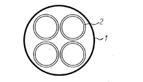
図1と図2は本発明の第1の実施形態を示す図である。先ず図1に示されるように、外側鋼管1の内部に複数本の内側鋼管2を挿入する。外側鋼管1及び内側鋼管2としては通常の機械構造用の鋼管を用いることができるが、強化用の合金元素を添加した高強度鋼管を使用してもよい。本発明では外側鋼管1の内部に複数本の内側鋼管2を圧入する必要はないので、図1のようにゆとりを持たせて内側鋼管2を挿入することができる。なお内側鋼管2は複数本とし、この実施形態では4本である。また内側鋼管2の断面形状は円形であっても角形その他の異形であってもよいが、この実施形態では通常の丸鋼管である。
Hereinafter, preferred embodiments of the present invention will be described with reference to the drawings.
1 and 2 are views showing a first embodiment of the present invention. First, as shown in FIG. 1, a plurality of
次に図1の状態の内部に複数本の内側鋼管2が挿入された外側鋼管1を、ダイスを用いて引抜き加工する。このダイスには複数本の内側鋼管2の断面形状に対応した孔型が形成されており、引抜き加工によって外側鋼管1の管壁は内側に塑性変形し、図2に示す断面形状の複合管構造となる。このとき、外側鋼管1の管壁のうち、角部に位置する内側鋼管2の外周面に沿った部分の変形量は小さいが、内側鋼管2相互間の部分は内側に大きく絞り込まれる。
Next, the
その結果、外側鋼管1の管壁の大部分は内側鋼管2の外周面に圧着されるが、一部は非接触状態となる。そして本発明では、外側鋼管1の内周長のうち内側鋼管2との非接触長の和が、外側鋼管1の内周長の20%以下となるようにする。非接触長は外側鋼管1の絞込み量により決定され、その絞込み量はダイスの孔型により決定されるので、非接触長の和を外側鋼管1の内周長の20%以下となるようにすることは、引抜き加工を行えば容易である。本発明において非接触長の和を外側鋼管1の内周長の20%以下としたのは、非接触長の和がこれよりも大きくなると外側鋼管1のみが変形する可能性が生じ、衝突エネルギー吸収特性の向上効果が不十分となる可能性があるためである。なお非接触長の和の下限は内側鋼管2の形状や本数により変化するが、ゼロとすることは不可能であり、実際には少なくとも1%程度となる。
As a result, most of the tube wall of the
この引抜き加工に伴い、外側鋼管1は加工硬化によって機械的強度が上がり、曲げや圧壊時における衝突エネルギー吸収特性が向上する。一方、内側鋼管2は延性を残したままであるが、外周を外側鋼管1により強力に固定されているので強い衝突エネルギーを受けない限りは相互の位置がずれたりすることはない。
Along with this drawing process, the
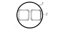
上記した第1の実施形態では、外側鋼管1の内部に4本の内側鋼管2を挿入したが、図3、図4に示す第2の実施形態ではその数を2本とした。この場合にも外側鋼管1の内周長に対する非接触長の和を20%以下となるようにする。この値はダイスの孔型によって決定することができることは上記と同様である。このほか、外側鋼管1の内部に挿入する内側鋼管2の本数を3本としたり、5本、6本とすることも可能である。しかしあまり本数を増加させると引抜き加工時の位置決めが行いにくくなるので、2〜6本が適切な本数である。
In the first embodiment described above, four
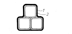
また内側鋼管2は異形管であってもよく、図5、図6に示す第3の実施形態では内側鋼管2は角管である。この場合には内側鋼管2が丸管である場合よりも、外側鋼管1の内周長に対する非接触長の和の比率を更に下げることが可能となる。しかし角管は平面により構成されているため、衝撃を受ける方向によっては変形が生じ易くなる。このため、方向による衝突エネルギー吸収特性の差を考慮した配置が必要である。
The
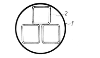
図7、図8は内側鋼管2を3本の角管とした第4の実施形態を示す。この場合にも上記した他の実施形態と同様の作用効果を得ることができる。
7 and 8 show a fourth embodiment in which the
図9、図10は第5の実施形態を示す。第1〜第4の実施形態では、内部鋼管2の外周面のプロフィールに合わせた孔型を有するダイスにて引抜き加工を施したが、この第5の実施形態では、円形の孔型を有するダイスを用いて外側鋼管1の径を円形のまま縮径させた。この場合には内部鋼管2が図10に示すように変形する。このようにして製造されたものも、他の実施形態と同様の作用効果を得ることができる。
9 and 10 show a fifth embodiment. In the first to fourth embodiments, the drawing process is performed with a die having a hole shape that matches the profile of the outer peripheral surface of the
以上に説明したように、本発明の衝突エネルギー吸収用鋼管は優れた衝突エネルギー吸収特性を示し、従来品よりも小さい断面積で大きい衝突エネルギー吸収効果を得ることができる。また外形状を様々に設定することができるため、十分な取り付けスペースしか確保できない場合にも対応可能である。このため、自動車の小型化・軽量化の動向に適した衝突エネルギー吸収用鋼管として、利用価値が高いものである。 As described above, the steel pipe for absorbing impact energy of the present invention exhibits excellent impact energy absorbing characteristics, and can obtain a large impact energy absorbing effect with a smaller cross-sectional area than that of the conventional product. In addition, since the outer shape can be set in various ways, it is possible to cope with a case where only a sufficient mounting space can be secured. For this reason, it has a high utility value as a collision energy absorbing steel pipe suitable for the trend of miniaturization and weight reduction of automobiles.
表1に示すほぼ同重量の3種類の鋼管にて衝撃曲げ試験を行った。各鋼管の断面は、図11に示すように、比較例1はφ40の鋼管、比較例2はφ40の外側鋼管とφ15.5の内側鋼管4本で構成された複合鋼管(外側鋼管の内周長の内非接触長の和は95%)、発明例1は比較例2の複合鋼管をダイスにて引抜き加工を施した複合引抜き鋼管(外側鋼管の内周長の内非接触長の和は7%)である。また各鋼管は、長さ1200mmである。
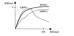
衝撃曲げ試験方法は、図12に示すように、スパン800mmで固定された支持台の上にサンプルを乗せ、衝突部のRが150mmである半円柱状の負荷子を55km/hで衝突させ、ロードセルで荷重を測定した。ロードセルにフィルターをかけ、振動の影響を取り除いた荷重の値と変位との関係を調べた。また、変位−荷重曲線から150mm変位までの吸収エネルギーを算出(変位−荷重曲線で囲まれた面積を計算)した。
An impact bending test was conducted on three types of steel pipes having the same weight as shown in Table 1. As shown in FIG. 11, the cross section of each steel pipe is as follows: Comparative Example 1 is a φ40 steel pipe, Comparative Example 2 is a composite steel pipe composed of an outer steel pipe of φ40 and four inner steel pipes of φ15.5 (the inner circumference of the outer steel pipe). (The sum of the inner non-contact length is 95%). Inventive Example 1 is a composite drawn steel pipe obtained by drawing the composite steel pipe of Comparative Example 2 with a die (the inner non-contact length of the inner peripheral length of the outer steel pipe is 7%). Each steel pipe has a length of 1200 mm.
As shown in FIG. 12, the impact bending test method places a sample on a support base fixed with a span of 800 mm, collides a semi-cylindrical load element having a collision portion R of 150 mm at 55 km / h, The load was measured with a load cell. A filter was applied to the load cell, and the relationship between the load value excluding the influence of vibration and the displacement was investigated. Also, the absorbed energy from the displacement-load curve to 150 mm displacement was calculated (the area surrounded by the displacement-load curve was calculated).
結果を表1及び図13に示す。図13より、比較例1の鋼管は断面2次モーメントが大きい為に衝突初期の荷重の上がり方は大きいが、断面が扁平し易い為、一度座屈をおこすと急激に荷重が低下する事が分かる。比較例2の複合鋼管は、内側鋼管が4本挿入されているため座屈は起こり難いが、外側鋼管と内側鋼管の間に大きな隙間がある為、衝突後外側鋼管と内側鋼管が接触するまではほぼ外側鋼管のみで荷重を受け持つ為、衝突初期の荷重の上がり方は小さい。一方発明例1の複合引抜き鋼管は、外側鋼管と内側鋼管の隙間が小さい為、衝突初期から全体で荷重を受け持つ為荷重の上がり方が大きく、また内側鋼管が4本挿入されているため座屈も起こり難い。また、本発明の複合引抜き鋼管は、引抜いた際に外側鋼管が加工硬化されている為、さらに衝突抵抗が増す。この為、衝突初期から150mm変位に至るまで安定して高い荷重を維持できる事が特徴である。以上の事から150mm吸収エネルギーは、表1に示すように比較例1が5200J、比較例2が5400Jであるのに対し、本発明の発明例1は6000Jと高い衝突エネルギー吸収能を示す。 The results are shown in Table 1 and FIG. From FIG. 13, the steel pipe of Comparative Example 1 has a large moment of inertia in the section, so the way of increasing the load at the beginning of the collision is large, but the section is easy to flatten. I understand. The composite steel pipe of Comparative Example 2 is unlikely to buckle because four inner steel pipes are inserted, but there is a large gap between the outer steel pipe and the inner steel pipe. Since only the outer steel pipe handles the load, the way of increasing the load at the beginning of the collision is small. On the other hand, the composite drawn steel pipe of Invention Example 1 has a small gap between the outer steel pipe and the inner steel pipe, so it takes over the entire load from the beginning of the collision, so the load rises greatly, and because four inner steel pipes are inserted, it buckles. It is hard to happen. Moreover, since the outer steel pipe is work-hardened when the composite drawn steel pipe of the present invention is drawn, the collision resistance is further increased. For this reason, it is characterized in that a high load can be stably maintained from the initial collision to a displacement of 150 mm. From the above, the 150 mm absorbed energy is 5200 J in Comparative Example 1 and 5400 J in Comparative Example 2 as shown in Table 1, whereas Inventive Example 1 of the present invention shows a high collision energy absorbing ability of 6000 J.
前記したように、本発明の複合引抜き鋼管は、重量同等の鋼管及び複合引抜き鋼管に対して高い吸収エネルギー能を示した。実施例のように使用すれば吸収エネルギーの点でメリットが出るが、必要に応じて板厚を薄くすれば、吸収エネルギーのメリットの変わりに軽量化のメリットを得る事もできる。また、図11を見ても分かるように本発明の複合引抜き鋼管は断面積が小さいので、小さな取り付けスペースにも取り付け可能である。 As described above, the composite drawn steel pipe of the present invention showed a high absorbed energy capability with respect to a steel pipe and a composite drawn steel pipe having the same weight. If it is used as in the embodiment, there is a merit in terms of absorbed energy, but if the plate thickness is reduced as necessary, the merit of weight reduction can be obtained instead of the merit of absorbed energy. Further, as can be seen from FIG. 11, the composite drawn steel pipe of the present invention has a small cross-sectional area, so that it can be mounted in a small mounting space.

1 外側鋼管
2 内側鋼管
1
Claims (4)
Priority Applications (1)
| Application Number | Priority Date | Filing Date | Title |
|---|---|---|---|
| JP2008247274A JP5316935B2 (en) | 2008-09-26 | 2008-09-26 | Steel pipe for impact energy absorption for automobile and method for manufacturing the same |
Applications Claiming Priority (1)
| Application Number | Priority Date | Filing Date | Title |
|---|---|---|---|
| JP2008247274A JP5316935B2 (en) | 2008-09-26 | 2008-09-26 | Steel pipe for impact energy absorption for automobile and method for manufacturing the same |
Publications (2)
| Publication Number | Publication Date |
|---|---|
| JP2010078062A true JP2010078062A (en) | 2010-04-08 |
| JP5316935B2 JP5316935B2 (en) | 2013-10-16 |
Family
ID=42208747
Family Applications (1)
| Application Number | Title | Priority Date | Filing Date |
|---|---|---|---|
| JP2008247274A Active JP5316935B2 (en) | 2008-09-26 | 2008-09-26 | Steel pipe for impact energy absorption for automobile and method for manufacturing the same |
Country Status (1)
| Country | Link |
|---|---|
| JP (1) | JP5316935B2 (en) |
Cited By (8)
| Publication number | Priority date | Publication date | Assignee | Title |
|---|---|---|---|---|
| WO2011033150A1 (en) * | 2009-09-15 | 2011-03-24 | Universidad De Alicante | Device for absorbing energy from motor vehicle collisions |
| CN103318112A (en) * | 2013-07-11 | 2013-09-25 | 吉林大学 | Heavy duty vehicle bionic rear bumper |
| CN104709208A (en) * | 2015-01-25 | 2015-06-17 | 吉林大学 | Bumper of imitating-ox-horn structure |
| KR101547279B1 (en) | 2013-12-16 | 2015-08-26 | 주식회사 성우하이텍 | Bumper beam unit for vehicles |
| KR20160107757A (en) * | 2015-03-05 | 2016-09-19 | 주식회사 성우하이텍 | Bumper beam unit for vehicles |
| US9694774B1 (en) | 2016-04-18 | 2017-07-04 | Sungwoo Hitech Co., Ltd. | Bumper beam unit for vehicles |
| US10131301B2 (en) | 2017-03-07 | 2018-11-20 | Ford Global Technology, Llc | Passive energy absorber structure adaptable to manage impact energy for different deformation targets and loads |
| CN108953450A (en) * | 2018-05-29 | 2018-12-07 | 北京理工大学 | A kind of shock resistance energy absorbing structure |
Families Citing this family (2)
| Publication number | Priority date | Publication date | Assignee | Title |
|---|---|---|---|---|
| CN105365725B (en) * | 2015-11-12 | 2022-02-01 | 重庆奔梦汽摩配件有限公司 | Energy-absorbing buffer automobile bumper with built-in capsule |
| CN105365726A (en) * | 2015-11-12 | 2016-03-02 | 重庆明华汽车零件有限公司 | Interlayer type energy absorption buffering automobile bumper with vertical pipes |
Citations (6)
| Publication number | Priority date | Publication date | Assignee | Title |
|---|---|---|---|---|
| JPH03275214A (en) * | 1990-03-26 | 1991-12-05 | Suzuka Fuji Xerox Kk | Multilayered metallic pipe, manufacture thereof and injecting needle |
| JPH06269853A (en) * | 1993-03-18 | 1994-09-27 | Toshida Kogyo Kk | Manufacture of double walled steel tube |
| JPH0952117A (en) * | 1995-08-10 | 1997-02-25 | Sumitomo Metal Ind Ltd | Manufacture of duplex steel tube excellent in damping property |
| JP2002284033A (en) * | 2001-03-27 | 2002-10-03 | Nippon Steel Corp | Strength member for automobile |
| JP2003312404A (en) * | 2002-04-24 | 2003-11-06 | Press Kogyo Co Ltd | Vehicular composite structural member |
| JP2003312535A (en) * | 2002-04-24 | 2003-11-06 | Jfe Steel Kk | Impact energy absorbing member |
-
2008
- 2008-09-26 JP JP2008247274A patent/JP5316935B2/en active Active
Patent Citations (6)
| Publication number | Priority date | Publication date | Assignee | Title |
|---|---|---|---|---|
| JPH03275214A (en) * | 1990-03-26 | 1991-12-05 | Suzuka Fuji Xerox Kk | Multilayered metallic pipe, manufacture thereof and injecting needle |
| JPH06269853A (en) * | 1993-03-18 | 1994-09-27 | Toshida Kogyo Kk | Manufacture of double walled steel tube |
| JPH0952117A (en) * | 1995-08-10 | 1997-02-25 | Sumitomo Metal Ind Ltd | Manufacture of duplex steel tube excellent in damping property |
| JP2002284033A (en) * | 2001-03-27 | 2002-10-03 | Nippon Steel Corp | Strength member for automobile |
| JP2003312404A (en) * | 2002-04-24 | 2003-11-06 | Press Kogyo Co Ltd | Vehicular composite structural member |
| JP2003312535A (en) * | 2002-04-24 | 2003-11-06 | Jfe Steel Kk | Impact energy absorbing member |
Cited By (10)
| Publication number | Priority date | Publication date | Assignee | Title |
|---|---|---|---|---|
| WO2011033150A1 (en) * | 2009-09-15 | 2011-03-24 | Universidad De Alicante | Device for absorbing energy from motor vehicle collisions |
| CN103318112A (en) * | 2013-07-11 | 2013-09-25 | 吉林大学 | Heavy duty vehicle bionic rear bumper |
| KR101547279B1 (en) | 2013-12-16 | 2015-08-26 | 주식회사 성우하이텍 | Bumper beam unit for vehicles |
| CN104709208A (en) * | 2015-01-25 | 2015-06-17 | 吉林大学 | Bumper of imitating-ox-horn structure |
| KR20160107757A (en) * | 2015-03-05 | 2016-09-19 | 주식회사 성우하이텍 | Bumper beam unit for vehicles |
| KR101685399B1 (en) * | 2015-03-05 | 2016-12-13 | 주식회사 성우하이텍 | Bumper beam unit for vehicles |
| US9694774B1 (en) | 2016-04-18 | 2017-07-04 | Sungwoo Hitech Co., Ltd. | Bumper beam unit for vehicles |
| US10131301B2 (en) | 2017-03-07 | 2018-11-20 | Ford Global Technology, Llc | Passive energy absorber structure adaptable to manage impact energy for different deformation targets and loads |
| CN108953450A (en) * | 2018-05-29 | 2018-12-07 | 北京理工大学 | A kind of shock resistance energy absorbing structure |
| CN108953450B (en) * | 2018-05-29 | 2020-02-07 | 北京理工大学 | Impact-resistant energy absorption structure |
Also Published As
| Publication number | Publication date |
|---|---|
| JP5316935B2 (en) | 2013-10-16 |
Similar Documents
| Publication | Publication Date | Title |
|---|---|---|
| JP5316935B2 (en) | Steel pipe for impact energy absorption for automobile and method for manufacturing the same | |
| TWI583579B (en) | Collision box and manufacturing method thereof | |
| EP3357600B1 (en) | Bumper member joining method | |
| CN106794733B (en) | Connector | |
| US8360490B2 (en) | Bumper crossbeam as component of a bumper of a motor vehicle | |
| CN103459239B (en) | Metallic hollow column-like member | |
| WO2011126146A1 (en) | Collision energy absorbing structure | |
| JP2004036944A (en) | Piping joint structure and its manufacturing method | |
| US20150048635A1 (en) | Bumper reinforcement and method of manufacturing the same | |
| US5836189A (en) | Method of manufacturing a pipe having sections with different cross-sectional configurations | |
| JP2005147365A (en) | Retainer for conical roller bearing and assembling method of conical roller bearing | |
| US20190374994A1 (en) | Joining method for members and joint body | |
| JPH09254808A (en) | Aluminum alloy extruded square pipe for front side member excellent in axial compression characteristics | |
| JP2006247748A (en) | Pipe integrally equipped with flange, more particularly pipe integrally equipped with flange composed of flexibly rolled material for vehicle and body structure | |
| KR20150123234A (en) | Formed material manufacturing method and formed material | |
| JP2003312535A (en) | Impact energy absorbing member | |
| JP2001138841A (en) | Shock absorber of vehicle | |
| JP5419401B2 (en) | Roll bending member and roll bending method | |
| JP3501228B2 (en) | Vehicle shock absorber | |
| JP5632147B2 (en) | Crash box | |
| JP4734129B2 (en) | Automotive strength members with excellent impact characteristics | |
| CN214147388U (en) | Impact-resistant steel pipe for automobile | |
| JP4054101B2 (en) | Automotive door reinforcement with excellent energy absorption at the time of collision | |
| JP2006137376A (en) | Strength member for automobile excellent in collision characteristic and structural member for automobile using the same | |
| JP2007232002A (en) | Structural member and structure |
Legal Events
| Date | Code | Title | Description |
|---|---|---|---|
| A621 | Written request for application examination |
Free format text: JAPANESE INTERMEDIATE CODE: A621 Effective date: 20100810 |
|
| A131 | Notification of reasons for refusal |
Free format text: JAPANESE INTERMEDIATE CODE: A131 Effective date: 20110816 |
|
| A977 | Report on retrieval |
Free format text: JAPANESE INTERMEDIATE CODE: A971007 Effective date: 20110818 |
|
| A521 | Written amendment |
Free format text: JAPANESE INTERMEDIATE CODE: A523 Effective date: 20110916 |
|
| A131 | Notification of reasons for refusal |
Free format text: JAPANESE INTERMEDIATE CODE: A131 Effective date: 20120327 |
|
| A521 | Written amendment |
Free format text: JAPANESE INTERMEDIATE CODE: A523 Effective date: 20120523 |
|
| A02 | Decision of refusal |
Free format text: JAPANESE INTERMEDIATE CODE: A02 Effective date: 20121204 |
|
| A521 | Written amendment |
Free format text: JAPANESE INTERMEDIATE CODE: A523 Effective date: 20130304 |
|
| A911 | Transfer of reconsideration by examiner before appeal (zenchi) |
Free format text: JAPANESE INTERMEDIATE CODE: A911 Effective date: 20130311 |
|
| TRDD | Decision of grant or rejection written | ||
| A01 | Written decision to grant a patent or to grant a registration (utility model) |
Free format text: JAPANESE INTERMEDIATE CODE: A01 Effective date: 20130614 |
|
| A61 | First payment of annual fees (during grant procedure) |
Free format text: JAPANESE INTERMEDIATE CODE: A61 Effective date: 20130627 |
|
| R151 | Written notification of patent or utility model registration |
Ref document number: 5316935 Country of ref document: JP Free format text: JAPANESE INTERMEDIATE CODE: R151 |
|
| S533 | Written request for registration of change of name |
Free format text: JAPANESE INTERMEDIATE CODE: R313533 |
|
| R350 | Written notification of registration of transfer |
Free format text: JAPANESE INTERMEDIATE CODE: R350 |