JP2010076517A - Control device of vehicle - Google Patents
Control device of vehicle Download PDFInfo
- Publication number
- JP2010076517A JP2010076517A JP2008244920A JP2008244920A JP2010076517A JP 2010076517 A JP2010076517 A JP 2010076517A JP 2008244920 A JP2008244920 A JP 2008244920A JP 2008244920 A JP2008244920 A JP 2008244920A JP 2010076517 A JP2010076517 A JP 2010076517A
- Authority
- JP
- Japan
- Prior art keywords
- air
- heating
- engine
- cooling
- mix door
- Prior art date
- Legal status (The legal status is an assumption and is not a legal conclusion. Google has not performed a legal analysis and makes no representation as to the accuracy of the status listed.)
- Granted
Links
Images


Landscapes
- Air-Conditioning For Vehicles (AREA)
Abstract
Description
本発明は、車両の制御技術に関し、特に、エンジンを自動的に停止させる機能を備えた車両における空調装置を制御する技術に関する。 The present invention relates to a vehicle control technique, and more particularly to a technique for controlling an air conditioner in a vehicle having a function of automatically stopping an engine.
車両の制御装置として、特許文献1には、車両が予め定めた条件を満たす場合に、エンジンを停止させる自動停止機能(いわゆるアイドリングストップ機能)を備えた車両において、この機能によりエンジンが停止した際に、空調装置の送風ファンを作動させて車室内の空調を行う技術が開示されている。
ここで、空調装置は、加熱用熱交換器と冷却用熱交換器とを備え、これらのそれぞれには、エンジンの駆動力を用いて加熱媒体や冷却媒体が供給されている。このため、アイドリングストップ機能によってエンジンが停止した場合、加熱用熱交換器又は冷却用熱交換器に対する加熱媒体又は冷却媒体の供給が停止することとなる。これにより、加熱用熱交換器の加熱性能又は冷却用熱交換器の冷却性能が低下してしまうため、これを補うべく、エアミックスドアを作動させて加熱空気と冷却空気との混合割合を調整している。 Here, the air conditioner includes a heating heat exchanger and a cooling heat exchanger, and a heating medium and a cooling medium are supplied to each of them using the driving force of the engine. For this reason, when the engine is stopped by the idling stop function, the supply of the heating medium or the cooling medium to the heating heat exchanger or the cooling heat exchanger is stopped. As a result, the heating performance of the heat exchanger for heating or the cooling performance of the heat exchanger for cooling deteriorates. To compensate for this, the mixing ratio of heated air and cooling air is adjusted by operating the air mix door. is doing.
しかしながら、エアミックスドアは、モータにより駆動するため、頻繁に作動した場合には、乗員にとって耳障りとなる。特に、エンジンがアイドリングストップ機能により停止している場合には、この作動音が顕著に露呈してしまう。 However, since the air mix door is driven by a motor, it becomes annoying to the occupant when operated frequently. In particular, when the engine is stopped by the idling stop function, this operating sound is remarkably exposed.
従って、本発明の目的は、エンジンの自動停止時に、空調性能を確保しながら、エアミックスドアのモータの作動音の発生頻度を低減することにある。 Therefore, an object of the present invention is to reduce the frequency of occurrence of operating noise of the motor of the air mix door while ensuring air conditioning performance when the engine is automatically stopped.
上記課題を解決するため、本発明においては、予め定めた条件が成立した場合に、エンジンを自動停止する自動停止手段と、車室内に空調空気を吹き出す吹出部を有する空調手段と、車室内の実室温が目標室温に近づくように前記空調手段を制御する空調制御手段と、を備え、前記空調手段が、前記吹出部に連通した空気通路と、前記空気通路に設けられ、前記吹出部へ空気を圧送する送風機と、前記空気通路に設けられ、前記送風機により圧送される空気を冷却する冷却手段と、前記空気通路に設けられ、前記送風機により圧送される空気を加熱する加熱手段と、前記空気通路に設けられ、前記吹出部から吹き出される空調空気の、前記冷却手段により冷却された空気と、前記加熱手段により加熱された空気と、の混合割合を調整するエアミックスドアと、前記エアミックスドアを駆動するモータと、を備えた車両の制御装置において、前記空調制御手段は、前記エアミックスドアの開度を規定する前記モータに対する制御量を、前記自動停止手段による前記エンジンの自動停止中は、そうでない場合よりも増大補正することを特徴とする車両の制御装置が提供される。 In order to solve the above-described problem, in the present invention, when a predetermined condition is satisfied, an automatic stop unit that automatically stops the engine, an air conditioning unit that has a blow-out unit that blows conditioned air into the vehicle interior, Air-conditioning control means for controlling the air-conditioning means so that the actual room temperature approaches the target room temperature, the air-conditioning means being provided in the air passage, the air passage being provided with air to the blow-out portion A cooling device provided in the air passage and for cooling air pumped by the blower, a heating device provided in the air passage for heating the air pumped by the blower, and the air Air that is provided in the passage and adjusts the mixing ratio of the air cooled by the cooling means and the air heated by the heating means of the conditioned air blown from the blowing portion And a motor for driving the air mix door, wherein the air conditioning control means is configured to control a control amount for the motor that defines an opening degree of the air mix door by the automatic stop means. There is provided a vehicle control device that performs an increase correction during the automatic stop of the engine as compared with a case where the engine is not.
本発明によれば、前記空調制御手段は、前記エアミックスドアの開度を規定する前記モータに対する制御量を、前記自動停止手段による前記エンジンの自動停止中は、そうでない場合よりも増大補正するため、前記空調装置の空調性能を確保しながら、前記エアミックスドアを作動する前記モータの作動音の発生頻度を低減することができる。 According to the present invention, the air conditioning control means corrects the control amount for the motor that defines the opening of the air mix door to be increased during the automatic stop of the engine by the automatic stop means than when it is not. Therefore, it is possible to reduce the frequency of occurrence of the operation sound of the motor that operates the air mix door while ensuring the air conditioning performance of the air conditioner.
また、本発明においては、前記エアミックスドアは、運転席側に供給する空調空気における前記冷却された空気と前記加熱された空気との混合割合を調整する第1のエアミックスドアと、助手席側に供給する空調空気における前記冷却された空気と前記加熱された空気との混合割合を調整する第2のエアミックスドアと、を備え、前記モータは、前記第1のエアミックスドアを作動する第1のモータと、前記第2のエアミックスドアを作動する第2のモータと、を備え、前記空調制御手段は、前記第1及び第2のモータを独立して制御する構成であってもよい。このように、前記空調制御手段が前記第1及び第2のモータを独立して制御する構成とすると、前記モータの作動音の発生頻度が更に増加するが、前記モータに対する制御量を増大補正することにより、前記モータの作動音の発生頻度を低減することができる。 In the present invention, the air mix door includes a first air mix door that adjusts a mixing ratio of the cooled air and the heated air in the conditioned air supplied to the driver's seat, and a passenger seat. A second air mix door that adjusts a mixing ratio of the cooled air and the heated air in the conditioned air supplied to the side, and the motor operates the first air mix door A first motor and a second motor for operating the second air mix door, wherein the air conditioning control means controls the first and second motors independently. Good. Thus, when the air-conditioning control means controls the first and second motors independently, the frequency of operation noise of the motor further increases, but the control amount for the motor is increased and corrected. As a result, the frequency of operation noise of the motor can be reduced.
また、本発明においては、前記空調手段は、前記冷却手段に冷却媒体を供給する冷却媒体供給手段と、前記加熱手段に加熱媒体を供給する加熱媒体供給手段と、を更に備え、前記冷却媒体供給手段及び前記加熱媒体供給手段の少なくともいずれか一方は、エンジンの駆動力を用いることにより、前記冷却手段に前記冷却媒体を供給し、又は前記加熱手段に前記加熱媒体を供給する構成であってもよい。この構成によれば、前記加熱媒体供給手段、前記冷却媒体供給手段の少なくともいずれか一方が、エンジンの駆動力を用いて前記供給処理を行うため、前記自動停止手段によるエンジンの自動停止中は、前記加熱媒体又は前記冷却媒体の供給が停止されることとなる。このため、前記冷却手段の冷却性能、前記加熱手段の加熱性能の少なくともいずれか一方が低下するため、前記エアミックスドアの開度調整が頻繁に行われることとなる。このような状態で、前記モータに対する制御量を増大補正することにより、前記モータの作動音の発生頻度をより効果的に低減することができる。 In the present invention, the air conditioning unit further includes a cooling medium supply unit that supplies a cooling medium to the cooling unit, and a heating medium supply unit that supplies a heating medium to the heating unit, and the cooling medium supply At least one of the means and the heating medium supply means may be configured to supply the cooling medium to the cooling means or supply the heating medium to the heating means by using the driving force of the engine. Good. According to this configuration, since at least one of the heating medium supply unit and the cooling medium supply unit performs the supply process using the driving force of the engine, during the automatic stop of the engine by the automatic stop unit, The supply of the heating medium or the cooling medium is stopped. For this reason, since at least one of the cooling performance of the cooling means and the heating performance of the heating means is lowered, the opening adjustment of the air mix door is frequently performed. In such a state, by increasing and correcting the control amount for the motor, it is possible to more effectively reduce the frequency of occurrence of operating noise of the motor.
また、本発明においては、前記空調手段は、前記冷却媒体又は前記冷却された空気の温度を検出する第1温度検出手段と、前記加熱媒体又は前記加熱された空気の温度を検出する第2温度検出手段と、を備え、前記空調制御手段は、前記自動停止手段によるエンジンの自動停止中は、前記第1又は前記第2温度検出手段で検出した温度の変化量に基づいて、前記モータを制御する構成であってもよい。この構成によれば、エンジンが停止されている間は、前記加熱用熱交換器の加熱性能又は前記冷却用熱交換器の冷却性能が低下していくため、それに応じて前記モータを駆動していく必要があるが、前記モータに対する制御量を増大補正することにより、前記モータの作動音の発生頻度を低減することができる。 In the present invention, the air conditioning unit includes a first temperature detecting unit that detects a temperature of the cooling medium or the cooled air, and a second temperature that detects a temperature of the heating medium or the heated air. Detecting means, and the air conditioning control means controls the motor based on the amount of change in temperature detected by the first or second temperature detecting means during the automatic stop of the engine by the automatic stopping means. It may be configured to. According to this configuration, while the engine is stopped, the heating performance of the heating heat exchanger or the cooling performance of the cooling heat exchanger decreases, so the motor is driven accordingly. Although it is necessary to increase the control amount for the motor, it is possible to reduce the frequency of the operation noise of the motor.
本発明によれば、エンジンの自動停止時に、空調性能を確保しながら、エアミックスドアのモータの作動音の発生頻度を低減することができる。 ADVANTAGE OF THE INVENTION According to this invention, the frequency of generation | occurrence | production of the operating sound of the motor of an air mix door can be reduced, ensuring air conditioning performance at the time of an engine automatic stop.
以下に、本発明の実施の形態について添付図面を参照して詳細に説明する。なお、以下に説明する実施の形態は、本発明の実現手段としての一例であり、本発明は、その趣旨を逸脱しない範囲で以下の実施形態を修正又は変形したものに適用可能である。 Hereinafter, embodiments of the present invention will be described in detail with reference to the accompanying drawings. The embodiment described below is an example as means for realizing the present invention, and the present invention can be applied to a modified or modified embodiment described below without departing from the spirit of the present invention.
[全体構成]
図1は、本発明の一実施形態に係る車両の側面図である。図2において、(a)は図1のA方向から見た矢視図であり、(b)は暖房強度設定部220を示す図であり、(c)は暖房ユニット210の構成を概念的に示す図である。図3は、本発明の一実施形態に係る空調ユニット110の構成を概念的に示す図である。図4において、(a)は加熱媒体W1の循環経路を示す図であり、(b)は冷却媒体W2の循環経路を示す図である。図5は、空調制御部130の機能的構成を示すブロック図である。
[overall structure]
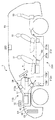
FIG. 1 is a side view of a vehicle according to an embodiment of the present invention. 2, (a) is an arrow view seen from the A direction of FIG. 1, (b) is a figure which shows the heating
本実施形態では、車両前後方向の長さが長い車両(例えば、ミニバンタイプ)を想定しており、車室内には、車両前後方向に並んで3列のシートS1、S2、S3が配設される。シートS1は、運転席及び助手席である。ダッシュボードDBの車両前後方向前方には、エンジンルームERが形成される。 In the present embodiment, a vehicle (for example, a minivan type) having a long length in the vehicle front-rear direction is assumed, and three rows of seats S1, S2, S3 are arranged in the vehicle front-rear direction. The The seat S1 is a driver seat and a passenger seat. An engine room ER is formed in front of the dashboard DB in the vehicle front-rear direction.
エンジンルームER内には、エンジンEGやトルクコンバータTC等が搭載される。エンジンEGは、種々のセンサから取得される情報に基づいて、エンジン制御部10によって制御される。エンジン制御部10は、例えば、CPU、ROM、RAM等を有するエンジンコントロールユニット(ECU)である。エンジン制御部10は、予め定めた条件が成立した場合に燃料噴射制御や点火制御等によりエンジンEGを自動停止させる自動停止部として機能する。すなわち、エンジン制御部10は、エンジンEGをアイドリングストップさせるか否かを制御する機能を有する。
An engine EG, a torque converter TC, and the like are mounted in the engine room ER. The engine EG is controlled by the
また、車両には、車室内の空調を行う車両用空調装置Sが配設される。 The vehicle is also provided with a vehicle air conditioner S for air conditioning the vehicle interior.
[車両用空調装置Sの構成]
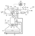
車両用空調装置Sは、車室内空間のうち、前席側空間に空調空気を吹き出す前部吹出部113を有する空調ユニット110と、車室内及び車室外の空調環境を検出する空調環境検出部120と、車室内の実室温が目標室温に近づくように空調ユニット110を制御する空調制御部130とを備える。
[Configuration of vehicle air conditioner S]
The vehicle air conditioner S includes an
空調ユニット110は、ダッシュボードDBの車両前後方向前方に設けられる。空調ユニット110は、前部吹出部113に連通した空気通路D1と、車室内又は車室外の空気を圧送する送風機111と、送風機111により圧送される空気を冷却する冷却部112bと、送風機111により圧送される空気を加熱する加熱部112aと、前部吹出部113から吹き出される空調空気の、冷却部112bにより冷却された空気と、加熱部112aにより加熱された空気との混合割合を調整するエアミックスドア114と、エアミックスドア114を駆動するモータ115とを備える。また、空調ユニット110は、加熱部112aに加熱媒体W1を供給する加熱媒体供給部112eと、冷却部112bに冷却媒体W2を供給する冷却媒体供給部112fとを備える。
The
送風機111は、空気通路D1に設けられる。また、送風機111は、車室内から取り込んだ内気を圧送するモードと、車室外から取り込んだ外気を圧送するモードとを切替弁B1を切り替えることにより選択可能である。
The
冷却部112bは、空気通路D1内において、送風機111の送風方向の下流側に設けられる。また、冷却部112bは、冷却用熱交換器で構成され、この冷却用熱交換器には、冷却媒体供給部112fによってエンジンEGの駆動力を用いることにより冷却媒体W2が供給される。
The
加熱部112aは、空気通路D1内において、冷却部112bに対して、送風機111の送風方向の下流側に設けられる。また、加熱部112aは、加熱用熱交換器で構成され、この加熱用熱交換器には、加熱媒体供給部112eによって加熱媒体W1が供給される。
The
加熱媒体供給部112eは、エンジンEGから熱を奪って高温となった冷却水を加熱媒体W1として加熱部112aに供給し、加熱部112aで熱を奪われて低温となった冷却水を再びエンジンEGに戻すウォーターポンプH1と、エンジンEGから熱を奪って高温となった冷却水を冷却するラジエータH2とを有する。
The heating
ウォーターポンプH1は、本実施形態では、モータを作動させることにより、冷却水を強制的に循環させる。ラジエータH2は、エンジンEGの車両前後方向前方であって、後述のコンデンサC2の車両前後方向後方のエンジンルームER内に配設され、フロントグリルから取り入れた走行風に加えて、エンジンEGの駆動力を用いて作動するファンF1によって冷却される。 In this embodiment, the water pump H1 forcibly circulates the cooling water by operating a motor. The radiator H2 is disposed in the engine room ER in front of the engine EG in the vehicle front-rear direction and behind the capacitor C2, which will be described later, in the vehicle front-rear direction. It is cooled by a fan F1 that operates using
冷却媒体供給部112fは、冷却部112bで空気の熱を奪って気化した低温・低圧の冷媒ガスを吸入圧縮して高温・高圧のガス冷媒とするコンプレッサC1と、コンプレッサC1からの高温・高圧のガス冷媒を冷却して凝縮液化して冷却部112bに供給するコンデンサC2とを有する。
The cooling
コンプレッサC1には、その出力軸にプーリP1が固定されており、そのプーリP1とエンジンEGのクランクシャフトCSに固定されたプーリP2との間でベルトB1が巻き回されている。これにより、エンジンEGの駆動力がコンプレッサC1に伝達される。コンデンサC2は、本実施形態では、ラジエータH2の車両前後方向前方のエンジンルームER内に配設され、走行風によって冷却される。 A pulley P1 is fixed to the output shaft of the compressor C1, and a belt B1 is wound between the pulley P1 and a pulley P2 fixed to the crankshaft CS of the engine EG. Thereby, the driving force of engine EG is transmitted to compressor C1. In the present embodiment, the capacitor C2 is disposed in the engine room ER in front of the radiator H2 in the vehicle front-rear direction, and is cooled by traveling wind.
従って、エンジン制御部10によってエンジンEGが停止されている場合には、クランクシャフトCSが回転しないため、コンプレッサC1が作動せず、冷却媒体W2の供給が停止されることとなる。なお、ウォーターポンプH1は、本実施形態では、モータにより駆動するものとしたが、コンプレッサC1と同様に、エンジンEGの駆動力を用いて作動する構成としてもよい。また、ウォーターポンプH1をエンジンEGの駆動力を用いて作動させ、コンプレッサC1をモータによって作動させる構成であってもよい。
Therefore, when the engine EG is stopped by the
エアミックスドア114及びモータ115は、空気通路D1内において、冷却部112bと加熱部112aとの間に設けられる。すなわち、エアミックスドア114は、冷却部112bで冷却された空気が加熱部112aを通過する割合を規定する。モータ115は、回動軸115cを有し、その回動軸115cにエアミックスドア114が固定される。モータ115には、例えば、ステッピングモータやサーボモータ、ポテンショ式モータ等のように回転角度を制御可能であるモータを用いることができる。
The
前部吹出部113は、フロントウインドウFWの内面に空調空気を吹き出す吹出口113aと、シートS1(前席)の乗員に向けて空調空気を吹き出す吹出口113bとを含む。吹出口113bは、シートS1(前席)に着座する乗員の顔面に向けて空調空気を吹き出す吹出口113b’と、シートS1(前席)に着座する乗員の足元に向けて空調空気を吹き出す吹出口113b”とを含む。
The
吹出口113aは、フロントウインドウFWの曇りを除去又は防止するデフロスタモードに用いられる。吹出口113b’、113b”は、フェイスモード、フットモードにそれぞれ用いられる。空調ユニット110は、吹出口113a、113bから空調空気を吹き出す第1モードと、吹出口113aのみから空調空気を吹き出す第2モードを含む複数の動作モードで動作可能である。
The
空調環境検出部120は、車室温度Trを検出する内気温度検出センサ121、外気温度Tambを検出する外気温度検出センサ122、加熱部112aで加熱された加熱空気の温度を検出する加熱空気温度検出センサ123(第2温度検出手段)と、冷却部112bで冷却された冷却空気の温度を検出する冷却空気温度検出センサ124(第1温度検出手段)と、日射量を検出する日射量検出センサ125とを有する。
The air-conditioning
内気温度検出センサ121は、ダッシュボードDBに設けられ、前席側の車室温度を検出する。加熱空気温度検出センサ123は、加熱部112aの送風方向に対する下流側に設けられ、冷却空気温度検出センサ124は、冷却部112bの送風方向に対する下流側に設けられる。加熱空気温度検出センサ123及び冷却空気温度検出センサ124は、加熱空気又は冷却空気の温度を常時検出している。しかし、加熱空気温度検出センサ123及び冷却空気温度検出センサ124は、アイドリングストップ機能によってエンジンEGが停止している間だけ検出するようにしても構わない。
The inside air
また、加熱空気温度検出センサ123は、加熱部112aで加熱された加熱空気の温度を検出するものとしたが、加熱媒体W1の温度を検出するものとしてもよい。同様に、冷却空気温度検出センサ124は、冷却部112bで冷却された冷却空気の温度を検出するものとしたが、冷却媒体W2の温度を検出するものとしてもよい。
Moreover, although the heating air
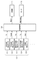
空調制御部130は、例えば、CPU、ROM、RAM等を有する車載コンピュータである。空調制御部130は、エアミックスドア114の開度を規定するモータ115に対する制御量をエンジン制御部10によるエンジンEGの自動停止中は、そうでない場合よりも増大補正する。すなわち、空調制御部130には、空調環境検出部120としての種々のセンサが接続されている。空調制御部130は、これらのセンサから入力される情報に基づいて、送風機111の電圧Vやエアミックスドア114の開度、すなわち、モータ115の回転角度Rを制御する。なお、空調制御部130の具体的な制御手順については後述する。
The air
また、車両用空調装置Sは、車室内空間のうち、後席側空間の暖房強度を乗員が設定可能な暖房強度設定部220と、暖房強度設定部220により設定された暖房強度に応じて、後席側空間に暖気を吹き出す後部吹出部213を有する暖房ユニット210とを備える。
In addition, the vehicle air conditioner S includes a heating
暖房ユニット210は、後部吹出部213に連通した空気通路D2と、車室内の空気を圧送する送風機211と、送風機211により圧送される空気を加熱する加熱部212とを有する。
The
送風機211及び加熱部212は、空気通路D2内において、運転席及び助手席の上下方向下方に設けられる。加熱部212は、加熱用熱交換器で構成され、この加熱用熱交換器には、図4(a)で示すように、加熱媒体供給部112eによって空調ユニット110の加熱部112aに供給される加熱媒体W1と同じ加熱媒体が供給される。
The
後部吹出部213は、シートS1の上下方向下方に配設され、シートS2の乗員の足元に温風を吹き出す吹出口213aと、シートS2の上下方向下方に配設され、シートS3の乗員の足元に温風を吹き出す吹出口213bとを含む。
The
暖房強度設定部220は、ルーフ部R2の車室側に配設され、送風機211の送風能力をユーザが設定可能である。すなわち、送風能力は、本実施形態では送風強度であり、図2(b)で示すように、「OFF・1・2・3」の4段階に設定することができる。更に、ユーザは、後席の乗員の足元に空調空気を吹き出すモード(フットモード)と、後席の乗員の顔面周辺に空調空気を吹き出すモード(フェイスモード)とに設定可能である。なお、これらのフットモードとフェイスモードとを同時に設定することも可能である。
The heating
また、暖房強度設定部220は、本実施形態では、送風機211の送風能力を設定可能であるものとしたが、加熱部212の加熱能力をユーザが設定可能としてもよい。
In the present embodiment, the heating
[空調制御部130の制御について]
図6は、空調制御部130の制御手順を示す図である。まず、ステップS101において、各種のセンサで検出された情報を読み込む。具体的には、車室温度Tr、外気温度Tamb、日射量Sun、冷却空気温度Te、加熱空気温度Tw、乗員によって設定された空調ユニット110の設定温度Tsetを読み込む。
[Control of air conditioning control unit 130]
FIG. 6 is a diagram illustrating a control procedure of the air
次に、ステップS102において、目標車室温度Ttargetを(式1)を用いて算出する。なお、(式1)のfは演算式であることを示す。 Next, in step S102, the target vehicle compartment temperature Ttarget is calculated using (Equation 1). Note that f in (Expression 1) indicates an arithmetic expression.
Ttarget=f(Tamb,Sun,Tset)・・・(式1)
次に、ステップS103において、車室温度Trが目標車室温度Ttargetと同値となるように、空調ユニット110の送風機111の風量及び空調空気の温度を算出する。そして、ステップS104において、ステップS103で算出された送風機111の風量及び空調空気の温度に基づいて、送風機111の電圧及びエアミックスドア114の開度を算出する。
Ttarget = f (Tamb, Sun, Tset) (Formula 1)
Next, in step S103, the air volume of the
次に、ステップS105において、車室温度Trと目標車室温度Ttargetとの差分(絶対値)が閾値th1以下であるか否かを判定する。ステップS105で差分が閾値th1以下であると判定された場合には、ステップS106において、アイドリングストップ許可をエンジン制御部10に送信する。一方、ステップS105で差分が閾値th1よりも大きいと判定された場合には、ステップS106及びステップS107の処理を行わずにステップS109に進む。
Next, in step S105, it is determined whether or not the difference (absolute value) between the passenger compartment temperature Tr and the target passenger compartment temperature Ttarget is equal to or less than a threshold th1. If it is determined in step S105 that the difference is equal to or smaller than the threshold th1, an idling stop permission is transmitted to the
次に、ステップS107において、空調制御部130がエンジン制御部10からアイドリングストップの実行を受信したか否かを判定する。ステップS107でアイドリングストップの実行を受信したと判定された場合には、ステップS108において、エアミックスドア114の開度補正処理を行う。なお、エアミックスドア開度補正処理の詳細については後述する。一方、ステップS107でアイドリングストップの実行を受信しなかったと判定された場合には、エアミックスドア開度補正処理を行わずにステップS109に進む。
Next, in step S107, it is determined whether or not the air
ステップS109では、送風機111の電圧V及びエアミックスドア114の開度Xに基づいて、送風機111及びモータ115を制御する。
In step S109, the
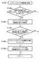
図7は、第1の実施形態に係るエアミックスドア開度補正処理(ステップS108)の詳細な動作手順を示す図である。 FIG. 7 is a diagram illustrating a detailed operation procedure of the air mix door opening correction process (step S108) according to the first embodiment.
まず、ステップS108aにおいて、加熱空気温度検出センサ123で検出された加熱空気温度Twが低下したか、又は冷却空気温度検出センサ124で検出された冷却空気温度Teが上昇したか否かを判定する。ステップS108aで加熱空気温度Twが低下したか、又は冷却空気温度Teが上昇したと判定された場合には、ステップS108bにおいて、加熱空気温度Twの低下量又は冷却空気温度Teの上昇量を補正するためのエアミックスドア114の開度補正量ΔXを算出する。すなわち、開度補正量ΔXは、エンジンEGがアイドリング停止したことに起因する変化量を補正する値である。一方、ステップS108aで加熱空気温度Twが低下せず、かつ、冷却空気温度Teが上昇していないと判定された場合には、エアミックスドア114の開度補正処理を行わずにステップS108の処理を終了する。エンジンEGがアイドリング停止しているとしても、加熱空気温度Tw又は冷却空気温度Teに変化がなければ、空調空気の温度に影響が出ないためである。
First, in step S108a, it is determined whether the heating air temperature Tw detected by the heating air
従って、空調制御部130は、エンジン制御部10によってエンジンEGが停止されている間、加熱空気温度検出センサ123で検出した加熱空気温度Tw及び冷却空気温度検出センサ124で検出した冷却空気温度Teの変化量ΔXに基づいて、モータ115を制御する。
Therefore, the air
なお、ステップS108aでは、エンジンEGが自動停止してから加熱空気温度Twが少しでも上昇した、又は冷却空気温度Teが少しでも低下した場合には、ステップS108bに進むこととするが、変化量の閾値を予め設定しておき、変化量がその閾値を越えているか否かによって判定してもよい。 In step S108a, if the heating air temperature Tw has risen even a little after the engine EG has automatically stopped or the cooling air temperature Te has fallen even a little, the process proceeds to step S108b. A threshold value may be set in advance, and the determination may be made based on whether or not the amount of change exceeds the threshold value.
次に、ステップS108cにおいて、ステップS108bで算出されたエアミックスドア114の開度補正量ΔXが閾値th2よりも大きいか否かを判定する。ステップS108cで開度補正量ΔXが閾値th2よりも大きい(ΔX>th2)と判定された場合には、ステップS108dにおいて、エアミックスドア114の開度Xを(式2)を用いて補正する。
Next, in step S108c, it is determined whether or not the opening correction amount ΔX of the
X=X+ΔX・・・(式2)
一方、ステップS108cで開度補正量ΔXが閾値th2以下である(ΔX<=th2)と判定された場合には、エアミックスドア114の開度補正処理を行わずにステップS108の処理を終了する。
X = X + ΔX (Formula 2)
On the other hand, when it is determined in step S108c that the opening correction amount ΔX is equal to or less than the threshold th2 (ΔX <= th2), the opening correction process of the
その後、ステップS108eにおいて、エアミックスドア114の制御量単位をxからxよりも大きいx’に変更する。最後に、上述したステップS109において、この補正後のエアミックスドア114の開度Xに基づいて、エアミックスドアXのモータ115の回転角度をステップS108eで変更された制御量単位x’で制御する。
Thereafter, in step S108e, the control amount unit of the
従って、空調制御部130は、エンジン制御部10によってエンジンEGが停止されている間、エンジンEG作動中の制御量単位よりも大きい制御量単位でモータ115を駆動する。例えば、エンジン作動中におけるモータ115の1回当たりの回転角度が3°であった場合には、エンジンEGがアイドリング停止中にはモータ115の1回当たりの回転角度を6°に設定することにより、モータ115の作動音の発生頻度を半減させることができる。
Therefore, while the engine EG is stopped by the
以上述べた通り、本実施形態によれば、エンジンEGがアイドリング停止している間において、空調性能を確保しながら、エアミックスドア114のモータ115の作動音の発生頻度を低減することができる。
As described above, according to the present embodiment, it is possible to reduce the frequency of operation noise of the
なお、本実施形態では、エンジン制御部10と空調制御部130とが別々の制御装置からなるものとしたが、1つの制御装置がこれらの機能を備えていても構わない。また、本実施形態では、後席側の暖房を行う暖房ユニット210を備える構成としたが、暖房ユニット210は本発明を実施する上で必須の構成ではない。
In the present embodiment, the
[第1の実施形態の変形例]
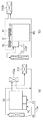
なお、上述の実施形態では、空調ユニット110は、運転席側と助手席側との間で同じ温度の空調空気を供給する構成としたが、図8で示すように、運転席側と助手席側との間で異なる温度の空調空気を供給可能である構成としてもよい。図8は、一実施形態の変形例に係る空調ユニット310を概念的に示す図である。
[Modification of First Embodiment]
In the above-described embodiment, the
エアミックスドア114は、運転席側に供給する空調空気における加熱空気と冷却空気との混合割合を調整するエアミックスドア114a(第1のエアミックスドア)と、助手席側に供給する空調空気における加熱空気と冷却空気との混合割合を調整するエアミックスドア114b(第2のエアミックスドア)とを含む。
The
モータ115は、エアミックスドア114aを作動するモータ115a(第1のモータ)と、エアミックスドア114bを作動するモータ115b(第2のモータ)とを含む。
The
エアミックスドア114の送風方向に対する上流側には、冷却部112bがダクトの幅全域に渡って配設され、エアミックスドア114の送風方向に対する下流側には、加熱部112aがダクトの幅全域に渡って配設される。また、加熱部112aの送風方向に対する下流側には、上述のフェイスモードやフットモード等の吹き出しモードを選択するためのモードダンパ116が設けられる。モードダンパ116は、ユーザの操作に応じて駆動するモータ117によって作動する。
On the upstream side of the
空調制御部130は、エアミックスドア114a、114bのモータ115a、115bを独立して制御する。これにより、運転席と助手席とで設定温度Tsetを変えることで、運転席と助手席との間で異なる温度の空調空気を供給することが可能となる。このような制御を行うと、2つのモータ115a、115bのそれぞれから作動音が発生することとなるため、本発明を適用することにより、作動音の発生頻度をより効果的に減少させることができる。
The air
<第2の実施形態>
上述の第1の実施形態では、エアミックスドア114の開度補正量ΔXが閾値th2よりも大きい場合にのみ、開度補正処理を行うものであった。一方、本実施形態では、エンジンEGがアイドリング停止した時からタイマのカウントを開始し、タイマが所定時間カウントを完了した場合にのみ開度補正処理を行う。すなわち、本実施形態では、エンジンEGがアイドリング停止してから所定時間経過した場合には、必ず開度補正処理を行うことにより、エンジン停止時における目標車室温度の維持に重点を置いた制御を行う。
<Second Embodiment>
In the first embodiment described above, the opening correction process is performed only when the opening correction amount ΔX of the
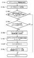
図9は、第2の実施形態に係るエアミックスドア開度補正処理(ステップS108)の詳細な制御手順を示す図である。まず、ステップS107でエンジン制御部10からアイドリングストップの実行を受信した場合には、ステップS108a’において、タイマのカウントを開始する。
FIG. 9 is a diagram illustrating a detailed control procedure of the air mix door opening correction process (step S108) according to the second embodiment. First, when the idling stop execution is received from the
そして、ステップS108b’において、加熱空気温度検出センサ123で検出された加熱空気温度Twが低下したか、又は冷却空気温度検出センサ124で検出された冷却空気温度Teが上昇したか否かを判定する。ステップS108b’で加熱空気温度Twが低下せず、かつ、冷却空気温度Teが上昇していないと判定された場合には、エアミックスドア114の開度補正処理を行わずにステップS108の処理を終了する。一方、ステップS108b’で加熱空気温度Twが低下したか、又は冷却空気温度Teが上昇したと判定された場合には、ステップS108c’において、タイマが所定時間のカウントを完了したか否かを判定する。
In step S108b ′, it is determined whether the heating air temperature Tw detected by the heating air
ステップS108c’でタイマが所定時間のカウントを完了していないと判定された場合には、エアミックスドア114の開度補正処理を行わずにステップS108の処理を終了する。一方、ステップS108c’でタイマが所定時間のカウントを完了したと判定された場合には、ステップS108d’において、エアミックスドア114の開度補正量ΔXを算出する。
If it is determined in step S108c 'that the timer has not completed counting the predetermined time, the process of step S108 is terminated without performing the opening correction process of the
そして、ステップS108e’において、ステップS104で算出されたエアミックスドア114の開度Xに開度補正量ΔXを(式3)のように加算する補正を行って、ステップS108f’でタイマをリセットする。
In step S108e ', correction is performed by adding the opening correction amount ΔX to the opening X of the
X=X+ΔX・・・(式3)
その後、ステップS108g’において、エアミックスドア114の制御量単位をxからxよりも大きいx’に変更する。最後に、上述したステップS109において、この補正後のエアミックスドア114の開度Xに基づいて、エアミックスドアXのモータ115の回転角度をステップS108g’で変更された制御量単位x’で制御する。
X = X + ΔX (Formula 3)
Thereafter, in step S108g ′, the control amount unit of the
以上述べた通り、本実施形態によれば、エンジンEGがアイドリング停止している際に、空調性能を確保しながら、エアミックスドア114のモータ115の作動音の発生頻度を低減することができる。
As described above, according to the present embodiment, when the engine EG is idling stopped, it is possible to reduce the frequency of operation noise of the
C2 コンデンサ
D1 空気通路
DB ダッシュボード
EG エンジン
ER エンジンルーム
FW フロントウインドウ
H2 ラジエータ
10 エンジン制御部
110 空調ユニット
111 送風機
112a 加熱部
112b 冷却部
113 前部吹出部
114 エアミックスドア
115 モータ
120 空調環境検出部
130 空調制御部
C2 Capacitor D1 Air passage DB Dashboard EG Engine ER Engine room FW Front
Claims (4)
車室内に空調空気を吹き出す吹出部を有する空調手段と、
車室内の実室温が目標室温に近づくように前記空調手段を制御する空調制御手段と、を備え、
前記空調手段が、
前記吹出部に連通した空気通路と、
前記空気通路に設けられ、前記吹出部へ空気を圧送する送風機と、
前記空気通路に設けられ、前記送風機により圧送される空気を冷却する冷却手段と、
前記空気通路に設けられ、前記送風機により圧送される空気を加熱する加熱手段と、
前記空気通路に設けられ、前記吹出部から吹き出される空調空気の、前記冷却手段により冷却された空気と、前記加熱手段により加熱された空気と、の混合割合を調整するエアミックスドアと、
前記エアミックスドアを駆動するモータと、
を備えた車両の制御装置において、
前記空調制御手段は、
前記エアミックスドアの開度を規定する前記モータに対する制御量を、前記自動停止手段による前記エンジンの自動停止中は、そうでない場合よりも増大補正することを特徴とする車両の制御装置。 Automatic stop means for automatically stopping the engine when a predetermined condition is satisfied;
Air-conditioning means having a blowing section for blowing out conditioned air into the vehicle interior;
Air conditioning control means for controlling the air conditioning means so that the actual room temperature in the passenger compartment approaches the target room temperature,
The air conditioning means
An air passage communicating with the blowing portion;
A blower that is provided in the air passage and that pumps air to the blowing section;
A cooling means provided in the air passage for cooling air pumped by the blower;
A heating means provided in the air passage for heating the air pumped by the blower;
An air mix door for adjusting the mixing ratio of the air cooled by the cooling means and the air heated by the heating means of the conditioned air blown out from the blowing portion provided in the air passage;
A motor for driving the air mix door;
In a vehicle control device comprising:
The air conditioning control means includes
A control apparatus for a vehicle, wherein the control amount for the motor that defines the opening of the air mix door is corrected to be increased during the automatic stop of the engine by the automatic stop means than when it is not.
運転席側に供給する空調空気における前記冷却された空気と前記加熱された空気との混合割合を調整する第1のエアミックスドアと、
助手席側に供給する空調空気における前記冷却された空気と前記加熱された空気との混合割合を調整する第2のエアミックスドアと、を備え、
前記モータは、
前記第1のエアミックスドアを作動する第1のモータと、
前記第2のエアミックスドアを作動する第2のモータと、を備え、
前記空調制御手段は、前記第1及び第2のモータを独立して制御することを特徴とする請求項1に記載の車両の制御装置。 The air mix door
A first air mix door for adjusting a mixing ratio of the cooled air and the heated air in the conditioned air supplied to the driver's seat side;
A second air mix door for adjusting a mixing ratio of the cooled air and the heated air in the conditioned air supplied to the passenger seat side,
The motor is
A first motor for operating the first air mix door;
A second motor for operating the second air mix door,
2. The vehicle control device according to claim 1, wherein the air conditioning control unit independently controls the first and second motors.
前記冷却手段に冷却媒体を供給する冷却媒体供給手段と、
前記加熱手段に加熱媒体を供給する加熱媒体供給手段と、を更に備え、
前記冷却媒体供給手段及び前記加熱媒体供給手段の少なくともいずれか一方は、エンジンの駆動力を用いることにより、前記冷却手段に前記冷却媒体を供給し、又は前記加熱手段に前記加熱媒体を供給することを特徴とする請求項1又は2に記載の車両の制御装置。 The air conditioning means includes:
A cooling medium supply means for supplying a cooling medium to the cooling means;
A heating medium supply means for supplying a heating medium to the heating means,
At least one of the cooling medium supply means and the heating medium supply means supplies the cooling medium to the cooling means or supplies the heating medium to the heating means by using the driving force of the engine. The vehicle control device according to claim 1 or 2.
前記冷却媒体又は前記冷却された空気の温度を検出する第1温度検出手段と、
前記加熱媒体又は前記加熱された空気の温度を検出する第2温度検出手段と、を備え、
前記空調制御手段は、前記自動停止手段によるエンジンの自動停止中は、前記第1又は前記第2温度検出手段で検出した温度の変化量に基づいて、前記モータを制御することを特徴とする請求項3に記載の車両の制御装置。 The air conditioning means includes:
First temperature detecting means for detecting a temperature of the cooling medium or the cooled air;
A second temperature detecting means for detecting the temperature of the heating medium or the heated air,
The air conditioning control means controls the motor based on the amount of change in temperature detected by the first or second temperature detecting means while the engine is automatically stopped by the automatic stopping means. Item 4. The vehicle control device according to Item 3.
Priority Applications (1)
| Application Number | Priority Date | Filing Date | Title |
|---|---|---|---|
| JP2008244920A JP5176820B2 (en) | 2008-09-24 | 2008-09-24 | Vehicle control device |
Applications Claiming Priority (1)
| Application Number | Priority Date | Filing Date | Title |
|---|---|---|---|
| JP2008244920A JP5176820B2 (en) | 2008-09-24 | 2008-09-24 | Vehicle control device |
Publications (2)
| Publication Number | Publication Date |
|---|---|
| JP2010076517A true JP2010076517A (en) | 2010-04-08 |
| JP5176820B2 JP5176820B2 (en) | 2013-04-03 |
Family
ID=42207476
Family Applications (1)
| Application Number | Title | Priority Date | Filing Date |
|---|---|---|---|
| JP2008244920A Expired - Fee Related JP5176820B2 (en) | 2008-09-24 | 2008-09-24 | Vehicle control device |
Country Status (1)
| Country | Link |
|---|---|
| JP (1) | JP5176820B2 (en) |
Cited By (8)
| Publication number | Priority date | Publication date | Assignee | Title |
|---|---|---|---|---|
| WO2012035573A1 (en) * | 2010-09-14 | 2012-03-22 | 三菱電機株式会社 | Air-conditioning device |
| CN104057799A (en) * | 2013-03-18 | 2014-09-24 | 马自达汽车株式会社 | Vehicle Air-conditioning Control Apparatus |
| JP2014180892A (en) * | 2013-03-18 | 2014-09-29 | Mazda Motor Corp | Vehicle air conditioner control device |
| JP2014180882A (en) * | 2013-03-18 | 2014-09-29 | Mazda Motor Corp | Vehicle air conditioner control device |
| JP2014193640A (en) * | 2013-03-28 | 2014-10-09 | Japan Climate Systems Corp | Vehicle air conditioner |
| JP2015186963A (en) * | 2014-03-27 | 2015-10-29 | マツダ株式会社 | Vehicle air conditioner control device |
| JP2016120801A (en) * | 2014-12-24 | 2016-07-07 | マツダ株式会社 | Air conditioner for vehicle |
| KR101801230B1 (en) * | 2011-08-23 | 2017-11-24 | 한온시스템 주식회사 | Air conditioning system for automotive vehicles of idle stop and go type |
Citations (10)
| Publication number | Priority date | Publication date | Assignee | Title |
|---|---|---|---|---|
| JPH0717241A (en) * | 1993-06-30 | 1995-01-20 | Nissan Motor Co Ltd | Revolution controller for engine accessory |
| JPH07266840A (en) * | 1994-02-09 | 1995-10-17 | Nippondenso Co Ltd | Air conditioner for vehicle |
| JP2000280897A (en) * | 1999-03-31 | 2000-10-10 | Mitsubishi Electric Corp | Ventilation device for rolling stock |
| JP2001026214A (en) * | 1999-05-11 | 2001-01-30 | Denso Corp | Air conditioner for vehicle |
| JP2001180246A (en) * | 1999-12-28 | 2001-07-03 | Fuji Heavy Ind Ltd | Air conditioner for vehicle |
| JP2004243812A (en) * | 2003-02-12 | 2004-09-02 | Denso Corp | Air conditioner for vehicle |
| JP2004360580A (en) * | 2003-06-05 | 2004-12-24 | Honda Motor Co Ltd | Vehicle equipped with air-conditioner |
| JP3624617B2 (en) * | 1997-03-18 | 2005-03-02 | 株式会社日本自動車部品総合研究所 | Air conditioner for vehicles |
| JP2007269218A (en) * | 2006-03-31 | 2007-10-18 | Denso Corp | Vehicular air-conditioner |
| JP2008080889A (en) * | 2006-09-26 | 2008-04-10 | Calsonic Kansei Corp | Vehicular air conditioner |
-
2008
- 2008-09-24 JP JP2008244920A patent/JP5176820B2/en not_active Expired - Fee Related
Patent Citations (10)
| Publication number | Priority date | Publication date | Assignee | Title |
|---|---|---|---|---|
| JPH0717241A (en) * | 1993-06-30 | 1995-01-20 | Nissan Motor Co Ltd | Revolution controller for engine accessory |
| JPH07266840A (en) * | 1994-02-09 | 1995-10-17 | Nippondenso Co Ltd | Air conditioner for vehicle |
| JP3624617B2 (en) * | 1997-03-18 | 2005-03-02 | 株式会社日本自動車部品総合研究所 | Air conditioner for vehicles |
| JP2000280897A (en) * | 1999-03-31 | 2000-10-10 | Mitsubishi Electric Corp | Ventilation device for rolling stock |
| JP2001026214A (en) * | 1999-05-11 | 2001-01-30 | Denso Corp | Air conditioner for vehicle |
| JP2001180246A (en) * | 1999-12-28 | 2001-07-03 | Fuji Heavy Ind Ltd | Air conditioner for vehicle |
| JP2004243812A (en) * | 2003-02-12 | 2004-09-02 | Denso Corp | Air conditioner for vehicle |
| JP2004360580A (en) * | 2003-06-05 | 2004-12-24 | Honda Motor Co Ltd | Vehicle equipped with air-conditioner |
| JP2007269218A (en) * | 2006-03-31 | 2007-10-18 | Denso Corp | Vehicular air-conditioner |
| JP2008080889A (en) * | 2006-09-26 | 2008-04-10 | Calsonic Kansei Corp | Vehicular air conditioner |
Cited By (14)
| Publication number | Priority date | Publication date | Assignee | Title |
|---|---|---|---|---|
| JP5752135B2 (en) * | 2010-09-14 | 2015-07-22 | 三菱電機株式会社 | Air conditioner |
| CN103097832A (en) * | 2010-09-14 | 2013-05-08 | 三菱电机株式会社 | Air-conditioning device |
| WO2012035573A1 (en) * | 2010-09-14 | 2012-03-22 | 三菱電機株式会社 | Air-conditioning device |
| US9587861B2 (en) | 2010-09-14 | 2017-03-07 | Mitsubishi Electric Corporation | Air-conditioning apparatus |
| CN103097832B (en) * | 2010-09-14 | 2016-04-27 | 三菱电机株式会社 | Conditioner |
| KR101801230B1 (en) * | 2011-08-23 | 2017-11-24 | 한온시스템 주식회사 | Air conditioning system for automotive vehicles of idle stop and go type |
| JP2014180892A (en) * | 2013-03-18 | 2014-09-29 | Mazda Motor Corp | Vehicle air conditioner control device |
| JP2014180882A (en) * | 2013-03-18 | 2014-09-29 | Mazda Motor Corp | Vehicle air conditioner control device |
| US9422861B2 (en) | 2013-03-18 | 2016-08-23 | Mazda Motor Corporation | Vehicle air-conditioning control apparatus |
| JP2014180881A (en) * | 2013-03-18 | 2014-09-29 | Mazda Motor Corp | Vehicle air conditioner control device |
| CN104057799A (en) * | 2013-03-18 | 2014-09-24 | 马自达汽车株式会社 | Vehicle Air-conditioning Control Apparatus |
| JP2014193640A (en) * | 2013-03-28 | 2014-10-09 | Japan Climate Systems Corp | Vehicle air conditioner |
| JP2015186963A (en) * | 2014-03-27 | 2015-10-29 | マツダ株式会社 | Vehicle air conditioner control device |
| JP2016120801A (en) * | 2014-12-24 | 2016-07-07 | マツダ株式会社 | Air conditioner for vehicle |
Also Published As
| Publication number | Publication date |
|---|---|
| JP5176820B2 (en) | 2013-04-03 |
Similar Documents
| Publication | Publication Date | Title |
|---|---|---|
| JP5176820B2 (en) | Vehicle control device | |
| JP5594281B2 (en) | Air conditioner for vehicles | |
| US6732941B2 (en) | Air conditioner for vehicle | |
| US20120152512A1 (en) | Vehicle air-conditioning control apparatus | |
| JP3722041B2 (en) | Air conditioner for vehicles | |
| WO2016186170A1 (en) | Air conditioning device for vehicle | |
| JP6363972B2 (en) | Air conditioner for vehicles | |
| JP5492857B2 (en) | Air conditioning control device for vehicles | |
| JP6019776B2 (en) | Air conditioner for vehicles | |
| US20190039433A1 (en) | Vehicular air conditioning device | |
| JP5640936B2 (en) | Air conditioner for vehicles | |
| JP5549639B2 (en) | Air conditioner for vehicles | |
| JP2010120414A (en) | Air conditioner for vehicle | |
| JP2010076516A (en) | Air conditioner for vehicle | |
| JP6443054B2 (en) | Air conditioner for vehicles | |
| JP2004155299A (en) | Vehicular air conditioner | |
| JP6630615B2 (en) | Vehicle air conditioner | |
| JP4457301B2 (en) | Air conditioning system for vehicles | |
| JP6390364B2 (en) | Air conditioner for vehicles | |
| JP2002144840A (en) | Vehicular air conditioner | |
| JP3309750B2 (en) | Vehicle air conditioner | |
| JP6568812B2 (en) | Air conditioner for vehicles | |
| JP2008143406A (en) | Automatic air conditioner control device of automobile | |
| JP2007245989A (en) | Air conditioner for vehicle | |
| JP6107781B2 (en) | Vehicle control device |
Legal Events
| Date | Code | Title | Description |
|---|---|---|---|
| RD03 | Notification of appointment of power of attorney |
Free format text: JAPANESE INTERMEDIATE CODE: A7423 Effective date: 20101001 |
|
| RD04 | Notification of resignation of power of attorney |
Free format text: JAPANESE INTERMEDIATE CODE: A7424 Effective date: 20101001 |
|
| A621 | Written request for application examination |
Free format text: JAPANESE INTERMEDIATE CODE: A621 Effective date: 20110802 |
|
| A521 | Written amendment |
Free format text: JAPANESE INTERMEDIATE CODE: A523 Effective date: 20120723 |
|
| A977 | Report on retrieval |
Free format text: JAPANESE INTERMEDIATE CODE: A971007 Effective date: 20121207 |
|
| TRDD | Decision of grant or rejection written | ||
| A01 | Written decision to grant a patent or to grant a registration (utility model) |
Free format text: JAPANESE INTERMEDIATE CODE: A01 Effective date: 20121211 |
|
| A61 | First payment of annual fees (during grant procedure) |
Free format text: JAPANESE INTERMEDIATE CODE: A61 Effective date: 20121224 |
|
| R150 | Certificate of patent or registration of utility model |
Ref document number: 5176820 Country of ref document: JP Free format text: JAPANESE INTERMEDIATE CODE: R150 |
|
| LAPS | Cancellation because of no payment of annual fees |