JP2010076065A - Cutting apparatus, and rotating balance adjusting method of cutting blade - Google Patents
Cutting apparatus, and rotating balance adjusting method of cutting blade Download PDFInfo
- Publication number
- JP2010076065A JP2010076065A JP2008248618A JP2008248618A JP2010076065A JP 2010076065 A JP2010076065 A JP 2010076065A JP 2008248618 A JP2008248618 A JP 2008248618A JP 2008248618 A JP2008248618 A JP 2008248618A JP 2010076065 A JP2010076065 A JP 2010076065A
- Authority
- JP
- Japan
- Prior art keywords
- amplitude
- cutting
- cutting blade
- detection mechanism
- mass
- Prior art date
- Legal status (The legal status is an assumption and is not a legal conclusion. Google has not performed a legal analysis and makes no representation as to the accuracy of the status listed.)
- Granted
Links
- 238000005520 cutting process Methods 0.000 title claims abstract description 144
- 238000000034 method Methods 0.000 title claims description 7
- 238000001514 detection method Methods 0.000 claims abstract description 46
- 238000003780 insertion Methods 0.000 claims description 9
- 230000037431 insertion Effects 0.000 claims description 9
- 238000006243 chemical reaction Methods 0.000 claims description 6
- 230000003287 optical effect Effects 0.000 claims description 6
- 230000002093 peripheral effect Effects 0.000 claims description 3
- 235000012431 wafers Nutrition 0.000 description 22
- XLYOFNOQVPJJNP-UHFFFAOYSA-N water Substances O XLYOFNOQVPJJNP-UHFFFAOYSA-N 0.000 description 11
- 238000004140 cleaning Methods 0.000 description 5
- 238000003384 imaging method Methods 0.000 description 5
- PXHVJJICTQNCMI-UHFFFAOYSA-N Nickel Chemical compound [Ni] PXHVJJICTQNCMI-UHFFFAOYSA-N 0.000 description 4
- 238000010586 diagram Methods 0.000 description 4
- 239000000758 substrate Substances 0.000 description 4
- 239000006061 abrasive grain Substances 0.000 description 3
- 239000013307 optical fiber Substances 0.000 description 3
- 239000004065 semiconductor Substances 0.000 description 3
- 230000032258 transport Effects 0.000 description 3
- 230000001133 acceleration Effects 0.000 description 2
- 229910003460 diamond Inorganic materials 0.000 description 2
- 239000010432 diamond Substances 0.000 description 2
- 229910052759 nickel Inorganic materials 0.000 description 2
- XUIMIQQOPSSXEZ-UHFFFAOYSA-N Silicon Chemical compound [Si] XUIMIQQOPSSXEZ-UHFFFAOYSA-N 0.000 description 1
- 239000002390 adhesive tape Substances 0.000 description 1
- 239000000919 ceramic Substances 0.000 description 1
- 238000007796 conventional method Methods 0.000 description 1
- 238000001035 drying Methods 0.000 description 1
- 239000011521 glass Substances 0.000 description 1
- 238000003754 machining Methods 0.000 description 1
- 239000000463 material Substances 0.000 description 1
- 238000007747 plating Methods 0.000 description 1
- 239000011347 resin Substances 0.000 description 1
- 229920005989 resin Polymers 0.000 description 1
- 229910052710 silicon Inorganic materials 0.000 description 1
- 239000010703 silicon Substances 0.000 description 1
- 238000003860 storage Methods 0.000 description 1
- 208000024891 symptom Diseases 0.000 description 1
Images


Abstract
Description
本発明は、環状の切削ブレードがスピンドルに装着された切削手段を有する切削装置及び切削ブレードの回転バランス調整方法に関する。 The present invention relates to a cutting apparatus having a cutting means in which an annular cutting blade is mounted on a spindle, and a method for adjusting the rotational balance of the cutting blade.
シリコン基板にICやLSI等のデバイスが複数形成された半導体ウエーハや、電子部品に使用される各種セラミック基板、樹脂基板、ガラス基板等の被加工物は、切削装置によって個々のチップに分割され、分割されたチップは各種電子機器に広く利用されている。 Workpieces such as semiconductor wafers in which a plurality of devices such as IC and LSI are formed on a silicon substrate, various ceramic substrates used in electronic components, resin substrates, glass substrates, etc., are divided into individual chips by a cutting device, The divided chips are widely used in various electronic devices.
切削装置としては、被加工物を保持するチャックテーブルと、チャックテーブルに保持された被加工物を切削する環状の切削ブレードと、切削ブレードが装着されるスピンドルとを備えたダイサーと称される装置が広く使用されている。 As a cutting device, a device called a dicer comprising a chuck table for holding a workpiece, an annular cutting blade for cutting the workpiece held on the chuck table, and a spindle on which the cutting blade is mounted. Is widely used.
切削ブレードは、例えば数μm程度のダイヤモンド砥粒をニッケルメッキ等で固めた切刃を有しており、切削ブレードはマウントフランジと固定ナットとで挟持されてスピンドル先端に装着される。切削ブレードはスピンドルによって20000〜60000rpm等の高速で回転させられつつ被加工物へ切り込むことで切削が行われる。 The cutting blade has a cutting blade in which, for example, diamond abrasive grains of about several μm are hardened by nickel plating or the like, and the cutting blade is sandwiched between a mount flange and a fixing nut and attached to the tip of the spindle. Cutting is performed by cutting the cutting blade into the workpiece while being rotated by the spindle at a high speed such as 20000 to 60000 rpm.
スピンドルに装着される切削ブレードの着脱を可能とするために、切削ブレードの内径と切削ブレードを装着するマウントフランジのボス部との間には数μm程度の遊びを設ける必要がある。 In order to make it possible to attach and detach the cutting blade attached to the spindle, it is necessary to provide a play of about several μm between the inner diameter of the cutting blade and the boss portion of the mount flange to which the cutting blade is attached.
このため、スピンドルの回転中心と切削ブレードの回転中心とが完全に合致しない状態で切削ブレードがスピンドルに装着された場合には、回転バランスが崩れ、スピンドルが高速回転すると振動が発生し、切削ブレードがばたつくことになる。従って、正常な切削は行われず、被加工物には欠けやクラックが発生し、ひいては切削ブレードや被加工物を破損させてしまう恐れがある。 For this reason, when the cutting blade is mounted on the spindle in a state where the rotation center of the spindle and the rotation center of the cutting blade do not completely coincide with each other, the rotation balance is lost and vibration occurs when the spindle rotates at a high speed. Will flutter. Therefore, normal cutting is not performed, and there is a risk that the workpiece may be chipped or cracked, and consequently the cutting blade or workpiece may be damaged.
スピンドルに装着した切削ブレードの偏心ぶれを取り除くために、一般砥粒を含むドレッサーを切削することで切削ブレードを磨耗させて真円に近づけるドレス作業が広く行われている。 In order to remove the eccentric shake of the cutting blade mounted on the spindle, dressing work is performed widely in which the cutting blade is worn by cutting a dresser including general abrasive grains so as to approach a perfect circle.
しかし、特に硬度の高い切削ブレードや厚みが厚い切削ブレードでは、ドレス作業を行っても完全に真円を出すことは困難である。更に、切刃先端にV字形状が形成された切削ブレードの場合には、V形状を維持するためにもドレス作業を行うことができず、回転バランスを調整する必要があった。 However, with a cutting blade having a high hardness or a cutting blade having a large thickness, it is difficult to produce a perfect circle even if a dressing operation is performed. Furthermore, in the case of a cutting blade having a V-shape formed at the tip of the cutting edge, the dressing operation cannot be performed in order to maintain the V shape, and the rotation balance has to be adjusted.
特開2001−129743号公報には、複数種類のバランスウエートを用意することなく、精密なバランス調整を容易に行うことのできる切削装置の回転バランス調整機構が開示されている。 Japanese Patent Laid-Open No. 2001-129743 discloses a rotation balance adjustment mechanism of a cutting apparatus that can easily perform precise balance adjustment without preparing a plurality of types of balance weights.
また、スピンドルのハウジングに加速度センサを取り付けてスピンドルのアンバランス位置を検出する装置(例えば広島県福山市大門町5丁目6番45号に所在する大宮工業株式会社製の商品名「Myself−1」)を用いて、切削手段の回転バランスを調整する方法が提案されている。
しかし、特許文献1に開示された切削装置の回転バランス調整機構では、切削ブレードの径方向の振幅を検出する振幅検出機構及び切削ブレードの回転周期を検出する回転周期検出機構が設けられていないため、複数回の試行錯誤によりねじ穴に挿入するバランスウエート用ねじのねじ込みの程度を決定する必要があり、回転バランスの調整に時間を要するという問題がある。
However, the rotation balance adjustment mechanism of the cutting apparatus disclosed in
また、ハウジングに加速度センサを取り付ける方法では、回転バランス調整用に専用の装置が必要であるとともに実際に切削ブレードが装着されているスピンドルの振動は測定できないという問題がある。 Further, the method of attaching the acceleration sensor to the housing has a problem that a dedicated device is required for adjusting the rotational balance and vibration of the spindle on which the cutting blade is actually mounted cannot be measured.
本発明はこのような点に鑑みてなされたものであり、その目的とするところは、スピンドルに装着された切削ブレード自体の回転バランスを容易に調整可能な切削装置を提供することである。 The present invention has been made in view of the above points, and an object of the present invention is to provide a cutting apparatus capable of easily adjusting the rotational balance of the cutting blade itself mounted on the spindle.
本発明によると、被加工物を保持するチャックテーブルと、該チャックテーブルに保持された被加工物を切削する環状の切削ブレードがマウントフランジと固定ナットで挟持されてスピンドルに装着された切削手段とを備えた切削装置であって、回転する前記切削ブレードの径方向の振幅を検出する振幅検出機構と、前記切削ブレードの回転周期を検出する回転周期検出機構と、該振幅検出機構で検出された振幅と該回転周期検出機構で検出された回転周期とに基づいて、振幅データを作成する振幅データ作成手段と、該振幅データに基づいて前記切削手段の回転バランスを調整するための調整用物体の質量を演算する質量演算手段と、該質量演算手段で演算された質量の調整用物体が装着される回転バランス調整機構と、を具備したことを特徴とする切削装置が提供される。 According to the present invention, a chuck table for holding a workpiece, and a cutting means for attaching an annular cutting blade for cutting the workpiece held on the chuck table to a spindle by being sandwiched between a mount flange and a fixing nut. An amplitude detection mechanism for detecting a radial amplitude of the rotating cutting blade, a rotation period detection mechanism for detecting a rotation period of the cutting blade, and the amplitude detection mechanism An amplitude data creating means for creating amplitude data based on the amplitude and the rotation period detected by the rotation period detecting mechanism, and an adjustment object for adjusting the rotational balance of the cutting means based on the amplitude data Mass calculating means for calculating mass, and a rotation balance adjusting mechanism on which an object for adjusting the mass calculated by the mass calculating means is mounted. Cutting device is provided to symptoms.
好ましくは、振幅検出機構は、切削ブレードの外周縁を照射するように切削ブレードの一方の側に配設された発光手段と、発光手段に対向して切削ブレードの他方の側に配設された受光手段と、受光手段が受光した光量を電圧信号に変換する光電変換手段とを含んでいる。 Preferably, the amplitude detection mechanism is disposed on one side of the cutting blade so as to irradiate the outer peripheral edge of the cutting blade, and disposed on the other side of the cutting blade so as to face the light emitting means. It includes a light receiving means and a photoelectric conversion means for converting the amount of light received by the light receiving means into a voltage signal.
前記振幅データ作成手段は、光電変換手段が出力する電圧値の最大値と最小値と、回転周期検出機構で検出された回転周期に基づいて、切削ブレードの径方向の振幅データを作成する。 The amplitude data creating means creates amplitude data in the radial direction of the cutting blade based on the maximum value and the minimum value of the voltage value output from the photoelectric conversion means and the rotation period detected by the rotation period detection mechanism.
好ましくは、回転バランス調整機構は、固定ナットの周方向に等間隔で形成された複数のねじ穴と、これらのねじ穴に挿入可能な調整用ねじとを含んでおり、前記調整用物体は調整用ねじから構成される。好ましくは、回転周期検出機構は、光センサ又は磁気センサから構成される。 Preferably, the rotation balance adjustment mechanism includes a plurality of screw holes formed at equal intervals in the circumferential direction of the fixing nut, and an adjustment screw that can be inserted into these screw holes, and the adjustment object is adjusted. Consists of screws. Preferably, the rotation period detection mechanism is constituted by an optical sensor or a magnetic sensor.
本発明によると、振幅検出機構で検出された振幅と回転周期検出機構で検出された回転周期とに基づいて、振幅データ作成手段で振幅データを作成するので、この振幅データに基づいて切削ブレード自身の回転バランスを容易に調整することができる。 According to the present invention, the amplitude data is created by the amplitude data creation means based on the amplitude detected by the amplitude detection mechanism and the rotation period detected by the rotation period detection mechanism. Can be easily adjusted.
従って、従来のスピンドルハウジングの振動データで回転バランスを調整する方法に比べてより高精度な調整が可能となる。又、回転バランス調整用に専用の装置を必要とせず、装置の省スペース化が可能となる。 Therefore, it is possible to perform adjustment with higher accuracy than the conventional method of adjusting the rotation balance with the vibration data of the spindle housing. Further, a dedicated device for adjusting the rotation balance is not required, and the space of the device can be saved.
以下、本発明の実施形態を図面を参照して詳細に説明する。図1は半導体ウエーハをダイシングして個々のチップ(デバイス)に分割することのできる本発明実施形態に係る切削装置2の外観を示している。
Hereinafter, embodiments of the present invention will be described in detail with reference to the drawings. FIG. 1 shows an appearance of a
切削装置2の前面側には、オペレータが加工条件等の装置に対する指示を入力するための操作手段4が設けられている。装置上部には、オペレータに対する案内画面や後述する撮像手段によって撮像された画像が表示されるCRT等の表示手段6が設けられている。
On the front side of the
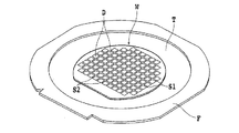
図2に示すように、ダイシング対象のウエーハWの表面においては、第1のストリートS1と第2ストリートS2とが直交して形成されており、第1のストリートS1と第2のストリートS2とによって区画されて多数のデバイスDがウエーハW上に形成されている。 As shown in FIG. 2, on the surface of the wafer W to be diced, the first street S1 and the second street S2 are formed orthogonally, and the first street S1 and the second street S2 A plurality of devices D are partitioned and formed on the wafer W.
ウエーハWは粘着テープであるダイシングテープTに貼着され、ダイシングテープTの外周縁部は環状フレームFに貼着されている。これにより、ウエーハWはダイシングテープTを介してフレームFに支持された状態となり、図1に示したウエーハカセット8中にウエーハが複数枚(例えば25枚)収容される。ウエーハカセット8は上下動可能なカセットエレベータ9上に載置される。
The wafer W is attached to a dicing tape T that is an adhesive tape, and the outer peripheral edge of the dicing tape T is attached to an annular frame F. As a result, the wafer W is supported by the frame F via the dicing tape T, and a plurality of wafers (for example, 25 sheets) are accommodated in the
ウエーハカセット8の後方には、ウエーハカセット8から切削前のウエーハWを搬出するとともに、切削後のウエーハをウエーハカセット8に搬入する搬出入手段10が配設されている。ウエーハカセット8と搬出入手段10との間には、搬出入対象のウエーハが一時的に載置される領域である仮置き領域12が設けられており、仮置き領域12には、ウエーハWを一定の位置に位置合わせする位置合わせ手段14が配設されている。
Behind the
仮置き領域12の近傍には、ウエーハWと一体となったフレームFを吸着して搬送する旋回アームを有する搬送手段16が配設されており、仮置き領域12に搬出されたウエーハWは、搬送手段16により吸着されてチャックテーブル18上に搬送され、このチャックテーブル18に吸引されるとともに、複数の固定手段19によりフレームFが固定されることでチャックテーブル18上に保持される。
In the vicinity of the
チャックテーブル18は、回転可能且つX軸方向に往復動可能に構成されており、チャックテーブル18のX軸方向の移動経路の上方には、ウエーハWの切削すべきストリートを検出するアライメント手段20が配設されている。
The chuck table 18 is configured to be rotatable and reciprocally movable in the X-axis direction. Above the movement path of the chuck table 18 in the X-axis direction, an
アライメント手段20は、ウエーハWの表面を撮像する撮像手段22を備えており、撮像により取得した画像に基づき、パターンマッチング等の処理によって切削すべきストリートを検出することができる。撮像手段22によって取得された画像は、表示手段6に表示される。
The
アライメント手段20の左側には、チャックテーブル18に保持されたウエーハWに対して切削加工を施す切削手段24が配設されている。切削手段24はアライメント手段20と一体的に構成されており、両者が連動してY軸方向及びZ軸方向に移動する。
On the left side of the alignment means 20, a cutting means 24 for cutting the wafer W held on the chuck table 18 is disposed. The
切削手段24は、回転可能なスピンドル26の先端に切削ブレード28が装着されて構成され、Y軸方向及びZ軸方向に移動可能となっている。切削ブレード28は撮像手段22のX軸方向の延長線上に位置している。
The
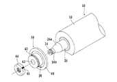
図3を参照すると、スピンドルと、スピンドルに装着されるマウントフランジとの関係を示す分解斜視図が示されている。スピンドルユニット30のスピンドルハウジング32中には、図示しないサーボモータにより回転駆動されるスピンドル26が回転可能に収容されている。スピンドル26はテーパ部26a及び先端小径部26bを有しており、先端小径部26bには雄ねじ34が形成されている。
Referring to FIG. 3, an exploded perspective view showing the relationship between the spindle and the mount flange attached to the spindle is shown. A
36はボス部(凸部)38と、ボス部38と一体的に形成された固定フランジ40とから構成されるマウントフランジであり、ボス部38には雄ねじ42が形成されている。さらに、マウントフランジ36は装着穴43を有している。
A
マウントフランジ36は、装着穴43をスピンドル26の先端小径部26b及びテーパ部26aに挿入して、ナット44を雄ねじ34に螺合して締め付けることにより、図4に示すようにスピンドル26の先端部に取り付けられる。ナット44には遮光テープ45が貼付されている。
The
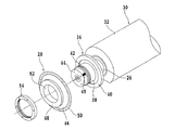
図4はマウントフランジ36が固定されたスピンドル26と、切削ブレード28との装着関係を示す分解斜視図である。切削ブレード28はハブブレードと呼ばれ、円形ハブ48を有する円形基台46の外周にニッケル母材中にダイヤモンド砥粒が分散された切刃50が電着されて構成されている。
FIG. 4 is an exploded perspective view showing the mounting relationship between the
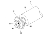
切削ブレード28の装着穴52をマウントフランジ36のボス部38に挿入し、固定ナット54をボス部38の雄ねじ42に螺合して締め付けることにより、図5に示すように切削ブレード28がスピンドル26に取り付けられる。
The mounting
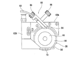
図6を参照すると、切削手段24の拡大斜視図が示されている。60は切削ブレード28をカバーするブレードカバーであり、このブレードカバー60には切削ブレード28の側面に沿って伸長する図示しない切削水ノズルが取り付けられている。切削水が、パイプ72を介して図示しない切削水ノズルに供給される。
Referring to FIG. 6, an enlarged perspective view of the cutting means 24 is shown. A
62は着脱カバーであり、ねじ64によりブレードカバー60に取り付けられる。着脱カバー62は、ブレードカバー60に取り付けられた際、切削ブレード28の側面に沿って伸長する切削水ノズル70を有している。切削水は、パイプ74を介して切削水ノズル70に供給される。
66はブレード検出ブロックであり、ねじ68によりブレードカバー60に取り付けられる。ブレード検出ブロック66には発光素子及び受光素子からなる図示しないブレードセンサが取り付けられており、このブレードセンサにより切削ブレード28の切刃50の状態を検出する。
A
ブレードセンサにより切刃50の欠け等を検出した場合には、切削ブレード28を新たな切削ブレードに交換する。76はブレードセンサの位置を調整するための調整ねじである。
When the cutting of the
ブレードセンサが本発明の振幅検出機構を兼用することもできる。ブレードセンサを振幅検出機構として用いる場合には、発光素子からの光ビームの概略半分程度が切刃50によりブロックされるように発光素子及び受光素子を切削ブレード28の切刃50を挟んで取り付ける。
The blade sensor can also serve as the amplitude detection mechanism of the present invention. When the blade sensor is used as the amplitude detection mechanism, the light emitting element and the light receiving element are attached with the
78は発光素子及び受光素子を有する光センサであり、着脱カバー62に取り付けられている。マウントフランジ36をスピンドル26に固定するナット44には遮光テープ45が貼付されている。光センサ78と遮光テープ45で回転周期検出機構を構成する。遮光テープ45に変わり、ナット44の外周の一部分を黒のマジックインクで塗りつぶすようにしても良い。
An
図7を参照すると、振幅検出機構の第2実施形態が示されている。60Aはブレードカバーであり、ブレードカバー60にスライド可能にスライドカバー62Aが取り付けられている。
Referring to FIG. 7, a second embodiment of the amplitude detection mechanism is shown.
ブレードカバー60Aには、発光部(端部)84からの光ビームが切削ブレード28の切刃50により概略半分程ブロックされるように光ファイバ82が取り付けられている。切削ブレード28の反対側には、受光部が発光部84に対向するようにフォトディテクタに接続された光ファイバが取り付けられている。
An
86は切削ブレード28の切刃50に対する発光部及び受光部の位置を調整する調整ねじであり、調整終了後には固定ねじ88により調整後の位置が固定される。
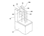
図8を参照すると、第3実施形態の振幅検出機構80Aの斜視図が示されている。振幅検出機構80AのU形状部材92は支持部材90上に取り付けられており、支持部材90は図1に示した切削装置2のチャックテーブル18の近辺に配設される。
Referring to FIG. 8, a perspective view of an
U形状部材92は切削ブレード28が進入するブレード進入部98を画成しており、発光素子94及び受光素子96はブレード進入部98の両側に取り付けられている。100はブレード進入部98に挿入された切削ブレード28に洗浄水を供給する洗浄水供給ノズルであり、102はエアーを供給するエアー供給ノズルである。
The
本実施形態の振幅検出機構80Aで切削ブレード28の径方向の振幅を検出するには、図示しないX軸送り機構及びY軸送り機構を駆動して、切削ブレード28をU形状部材92のブレード進入部98中に進入させる。
In order to detect the radial amplitude of the
そして、洗浄水供給ノズル100から切削ブレードに洗浄水を供給して切削ブレードを洗浄し、次いでエアー供給ノズル102からエアーを供給して切削ブレード28から洗浄水を吹き飛ばし、切削ブレードを乾燥する。
Then, cleaning water is supplied from the cleaning
切削ブレード28の乾燥が終了すると、図示しないZ軸送り機構を駆動して切削ブレード28の切刃50の高さを調整し、発光素子94から出射された光ビームの概略半分程度が切刃50によりブロックされるように設定する。この状態で切削ブレード28を20000〜60000rpmで回転させて切削ブレード28の径方向の振幅を検出する。
When drying of the
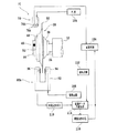
次に図9を参照して、回転周期検出機構78及び第3実施形態の振幅検出機構80Aを使用した切削ブレード28の回転バランス調整方法について図9乃至図12を参照して説明する。図9は回転バランス調整機構のブロック図である。
Next, a method for adjusting the rotational balance of the
図9において、光源104に接続された発光部78aと受光部78bを有する光センサ78と、ナット44に貼付された遮光テープ45により回転周期検出機構77を構成する。回転周期検出機構77で検出された回転周期112は記憶手段106に記憶されるとともに、後で説明する振幅データの作成に利用される。
In FIG. 9, a rotation
駆動回路108により発光素子94が駆動されると、発光素子94から光ビームが出射され、その一部が受光素子96により受光される。切削ブレード28は高速回転しているため、径方向の振動が発生し、受光素子96で受光する光量は切削ブレード28の振動に応じて変化する。
When the
受光素子96で受光された光量はフォトディテクタ等の光電変換手段110により電圧信号に変換される。振幅データ作成手段114では、光電変換手段110が出力する電圧値の最大値と最小値と、回転周期検出機構77で検出された回転周期112に基づいて、切削ブレード28の径方向の振幅データを作成する。
The amount of light received by the
この振幅データは、図10に示すように振幅の大きさ及び振幅が現れる切削ブレード28の角度位置のデータを含んでいる。図10において、符号118は固定ナット54の調整用ねじ挿入位置120に調整用ねじを挿入しない時の、切削ブレード28の第1振幅データを示している。固定ナット54には周方向に等間隔離間して複数の調整用ねじ挿入穴(図示せず)が形成されている。
As shown in FIG. 10, the amplitude data includes amplitude data and angular position data of the
符号122は、回転バランスが崩れていなかった場合、調整用ねじを調整用ねじ挿入穴120に挿入した際に得られるべき振幅データを示している。符号124は、調整用ねじ挿入穴120に調整用ねじを挿入した際に得られた第2振幅データを示している。
126は第1振幅データ118を打ち消すのに必要な振幅を示しており、第1振幅データ118の180度反対側に第1振幅データの大きさと同じ振幅を発生させることにより、回転バランスは修正される。
以下、図10の振幅データに対応する図11に示すベクトル図を参照して、第1振幅データ118を打ち消すのに必要な調整用ねじの質量を計算する。この調整用ねじの質量の計算は、図9の質量演算手段116により行われる。F1は第1振幅データ118に対応し、F3は第2振幅データ124に対応し、F2は振幅122に対応する。
Hereinafter, with reference to the vector diagram shown in FIG. 11 corresponding to the amplitude data of FIG. 10, the mass of the adjusting screw necessary to cancel the
図11において、θ1=30度の位置に第1振幅F1が検出され、θ2=90度の調整用ねじ挿入位置120に20mgの調整ねじを挿入した時に、θ3=60度の位置に第2振幅S3が検出され、第1振幅F1が8μm、第2振幅F3が13.84μmであった場合について計算する。
In FIG. 11, when the first amplitude F1 is detected at the position of θ1 = 30 degrees and a 20 mg adjustment screw is inserted into the adjustment
F3=F1+F2 よって、F1=F3−F2
F3=1.73F1 F2=20mgであるから
F3=F1cosθ5+F2cosθ4
・ 73F1=F1cos30°+20・cos30°
1.73F1−F1cos30°=20・cos30°
F1=(20・cos30°)/(1.73―cos30°)
≒20
よって、挿入すべき調整ねじの重さF1はF1≒20mgと算出される。
F3 = F1 + F2 Therefore, F1 = F3-F2
Because F3 = 1.73F1 F2 = 20 mg
F3 = F1 cos θ5 + F2 cos θ4
・ 73F1 = F1cos30 ° + 20 ・ cos30 °
1.73F1-F1cos30 ° = 20 · cos30 °
F1 = (20 ·
≒ 20
Therefore, the weight F1 of the adjusting screw to be inserted is calculated as F1≈20 mg.
従って、F1を打ち消すためには、180度回転したθ6=210度の調整用ねじ挿入穴に20mgの調整ねじを挿入する必要がある。 Therefore, in order to cancel F1, it is necessary to insert a 20 mg adjustment screw into the adjustment screw insertion hole of θ6 = 210 degrees rotated 180 degrees.
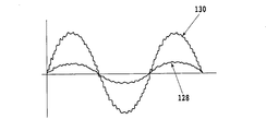
切削装置が固有の振動を有する場合等では、図12に示すように事前に低回転時の振幅を検出し振幅データ128を記憶しておき、回転バランス調整を行う際の振幅データ130から低回転時の振幅データ128を差し引くことにより、高精度の回転バランス調整方法が可能となる。
When the cutting device has inherent vibrations, the amplitude at the time of low rotation is detected in advance and the
18 チャックテーブル
26 スピンドル
28 切削ブレード
36 マウントフランジ
44 ナット
45 遮光テープ
54 固定ナット
77 回転周期検出機構
78 光センサ
80,80A 振幅検出機構
82 光ファイバ
84 発光部
94 発光素子
96 受光素子
98 ブレード進入部
114 振幅データ作成手段
116 質量演算手段
18 Chuck table 26
Claims (5)
回転する前記切削ブレードの径方向の振幅を検出する振幅検出機構と、
前記切削ブレードの回転周期を検出する回転周期検出機構と、
該振幅検出機構で検出された振幅と該回転周期検出機構で検出された回転周期とに基づいて、振幅データを作成する振幅データ作成手段と、
該振幅データに基づいて前記切削手段の回転バランスを調整するための調整用物体の質量を演算する質量演算手段と、
該質量演算手段で演算された質量の調整用物体が装着される回転バランス調整機構と、
を具備したことを特徴とする切削装置。 A cutting apparatus comprising: a chuck table for holding a workpiece; and a cutting means in which an annular cutting blade for cutting the workpiece held on the chuck table is sandwiched between a mount flange and a fixing nut and mounted on a spindle. Because
An amplitude detection mechanism for detecting the radial amplitude of the rotating cutting blade;
A rotation period detection mechanism for detecting a rotation period of the cutting blade;
Amplitude data creating means for creating amplitude data based on the amplitude detected by the amplitude detection mechanism and the rotation period detected by the rotation period detection mechanism;
A mass computing means for computing the mass of the adjusting object for adjusting the rotational balance of the cutting means based on the amplitude data;
A rotation balance adjusting mechanism to which an object for adjusting the mass calculated by the mass calculating means is mounted;
A cutting apparatus comprising:
前記切削ブレードの外周縁を照射するように該切削ブレードの一方の側に配設された発光手段と、
該発光手段に対向して前記切削ブレードの他方の側に配設された受光手段と、
該受光手段が受光した光量を電圧信号に変換する光電変換手段とを含み、
前記振幅データ作成手段は、該光電変換手段が出力する電圧値の最大値と最小値と、該回転周期検出機構で検出された回転周期に基づいて、前記切削ブレードの径方向の振幅データを作成する請求項1記載の切削装置。 The amplitude detection mechanism is:
A light emitting means disposed on one side of the cutting blade so as to irradiate the outer peripheral edge of the cutting blade;
A light receiving means disposed on the other side of the cutting blade opposite the light emitting means;
Photoelectric conversion means for converting the amount of light received by the light receiving means into a voltage signal,
The amplitude data creation means creates the amplitude data in the radial direction of the cutting blade based on the maximum and minimum values of the voltage value output from the photoelectric conversion means and the rotation period detected by the rotation period detection mechanism. The cutting device according to claim 1.
前記振幅検出機構で検出した前記切削ブレード回転時の径方向の第1の振幅と、前記回転周期検出機構で検出した回転周期とに基づいて、第1振幅データを形成する第1振幅検出ステップと、
該第1振幅検出ステップを実施した後、前記複数のねじ穴のうち所定位置のねじ穴に既知の質量の第1調整用ねじを挿入する第1調整用ねじ挿入ステップと、
該第1調整用ねじ挿入ステップを実施した後、前記振幅検出機構で検出した前記切削ブレード回転時の径方向の第2の振幅と、前記回転周期検出機構で検出した回転周期とに基づいて、第2振幅データを形成する第2振幅検出ステップと、
前記第1の振幅と前記第2の振幅の差及び前記第1調整用ねじの質量とに基づいて、該第1の振幅を打ち消すために挿入すべき調整用ねじの質量を算出する必要質量算出ステップと、
前記第1調整用ねじを取り外した後、前記第1振幅検出ステップで検出した第1の振幅位置と周方向180度反対側のねじ穴位置に、前記必要質量算出ステップで算出した質量の第2調整用ねじを挿入する第2調整用ねじ挿入ステップと、
を具備したことを特徴とする回転バランス調整方法。 The cutting apparatus according to claim 3, wherein the rotation balance is adjusted by adjusting the rotation balance of the cutting blade.
A first amplitude detection step for forming first amplitude data based on a first amplitude in a radial direction during rotation of the cutting blade detected by the amplitude detection mechanism and a rotation period detected by the rotation period detection mechanism; ,
A first adjustment screw insertion step of inserting a first adjustment screw having a known mass into a screw hole at a predetermined position among the plurality of screw holes after performing the first amplitude detection step;
After performing the first adjustment screw insertion step, based on the second amplitude in the radial direction during rotation of the cutting blade detected by the amplitude detection mechanism and the rotation period detected by the rotation period detection mechanism, A second amplitude detecting step for forming second amplitude data;
Based on the difference between the first amplitude and the second amplitude, and the mass of the first adjustment screw, the required mass calculation for calculating the mass of the adjustment screw to be inserted to cancel the first amplitude. Steps,
After removing the first adjustment screw, the second mass of the mass calculated in the required mass calculation step is placed at a screw hole position 180 degrees opposite to the first amplitude position detected in the first amplitude detection step. A second adjustment screw insertion step for inserting the adjustment screw;
A rotation balance adjustment method comprising:
Priority Applications (1)
| Application Number | Priority Date | Filing Date | Title |
|---|---|---|---|
| JP2008248618A JP5248250B2 (en) | 2008-09-26 | 2008-09-26 | Cutting device and method for adjusting rotational balance of cutting blade |
Applications Claiming Priority (1)
| Application Number | Priority Date | Filing Date | Title |
|---|---|---|---|
| JP2008248618A JP5248250B2 (en) | 2008-09-26 | 2008-09-26 | Cutting device and method for adjusting rotational balance of cutting blade |
Publications (2)
| Publication Number | Publication Date |
|---|---|
| JP2010076065A true JP2010076065A (en) | 2010-04-08 |
| JP5248250B2 JP5248250B2 (en) | 2013-07-31 |
Family
ID=42207098
Family Applications (1)
| Application Number | Title | Priority Date | Filing Date |
|---|---|---|---|
| JP2008248618A Active JP5248250B2 (en) | 2008-09-26 | 2008-09-26 | Cutting device and method for adjusting rotational balance of cutting blade |
Country Status (1)
| Country | Link |
|---|---|
| JP (1) | JP5248250B2 (en) |
Cited By (5)
| Publication number | Priority date | Publication date | Assignee | Title |
|---|---|---|---|---|
| JP2016112635A (en) * | 2014-12-12 | 2016-06-23 | Towa株式会社 | Cutting device and cutting method |
| JP2016122673A (en) * | 2014-12-24 | 2016-07-07 | Towa株式会社 | Cutting device and cutting method |
| CN106442535A (en) * | 2015-08-13 | 2017-02-22 | 维嘉数控科技(苏州)有限公司 | Cutter body breakage detection device |
| JP2017536251A (en) * | 2014-12-01 | 2017-12-07 | ラテュンデ アンド コーポレイテッド ゲーエムベーハー | Method for sawing long profiles and machine for cross-cutting long profiles |
| JP2020163546A (en) * | 2019-03-29 | 2020-10-08 | 株式会社小松製作所 | Industrial machine, decentration specification device, decentration specification method, and program |
Citations (7)
| Publication number | Priority date | Publication date | Assignee | Title |
|---|---|---|---|---|
| JPS61132813A (en) * | 1984-11-30 | 1986-06-20 | Nagase Tekkosho:Kk | Balance detecting display device of rotating body |
| JPH0328733A (en) * | 1989-06-26 | 1991-02-06 | Nagase Iron Works Co Ltd | Detector for balancing state and wearing state of grindstone |
| JPH04203544A (en) * | 1990-11-29 | 1992-07-24 | Nagase Iron Works Co Ltd | Balance correcting device for rotary body |
| JP2001170863A (en) * | 1999-12-20 | 2001-06-26 | Okamoto Machine Tool Works Ltd | Grinding device |
| JP2004338034A (en) * | 2003-05-15 | 2004-12-02 | Toshiba Mach Co Ltd | Method and apparatus for cooling main spindle of machine tool, and method of balancing the main spindle |
| JP2005199410A (en) * | 2004-01-19 | 2005-07-28 | Japan Science & Technology Agency | Method and apparatus for suppressing vibration in grinding machine having grinding wheel and machine tool having rotary cutter |
| JP2006272541A (en) * | 2005-03-28 | 2006-10-12 | Takashima Sangyo Kk | Rotation balancer |
-
2008
- 2008-09-26 JP JP2008248618A patent/JP5248250B2/en active Active
Patent Citations (7)
| Publication number | Priority date | Publication date | Assignee | Title |
|---|---|---|---|---|
| JPS61132813A (en) * | 1984-11-30 | 1986-06-20 | Nagase Tekkosho:Kk | Balance detecting display device of rotating body |
| JPH0328733A (en) * | 1989-06-26 | 1991-02-06 | Nagase Iron Works Co Ltd | Detector for balancing state and wearing state of grindstone |
| JPH04203544A (en) * | 1990-11-29 | 1992-07-24 | Nagase Iron Works Co Ltd | Balance correcting device for rotary body |
| JP2001170863A (en) * | 1999-12-20 | 2001-06-26 | Okamoto Machine Tool Works Ltd | Grinding device |
| JP2004338034A (en) * | 2003-05-15 | 2004-12-02 | Toshiba Mach Co Ltd | Method and apparatus for cooling main spindle of machine tool, and method of balancing the main spindle |
| JP2005199410A (en) * | 2004-01-19 | 2005-07-28 | Japan Science & Technology Agency | Method and apparatus for suppressing vibration in grinding machine having grinding wheel and machine tool having rotary cutter |
| JP2006272541A (en) * | 2005-03-28 | 2006-10-12 | Takashima Sangyo Kk | Rotation balancer |
Cited By (8)
| Publication number | Priority date | Publication date | Assignee | Title |
|---|---|---|---|---|
| JP2017536251A (en) * | 2014-12-01 | 2017-12-07 | ラテュンデ アンド コーポレイテッド ゲーエムベーハー | Method for sawing long profiles and machine for cross-cutting long profiles |
| JP2016112635A (en) * | 2014-12-12 | 2016-06-23 | Towa株式会社 | Cutting device and cutting method |
| JP2016122673A (en) * | 2014-12-24 | 2016-07-07 | Towa株式会社 | Cutting device and cutting method |
| CN106442535A (en) * | 2015-08-13 | 2017-02-22 | 维嘉数控科技(苏州)有限公司 | Cutter body breakage detection device |
| JP2020163546A (en) * | 2019-03-29 | 2020-10-08 | 株式会社小松製作所 | Industrial machine, decentration specification device, decentration specification method, and program |
| WO2020203844A1 (en) * | 2019-03-29 | 2020-10-08 | 株式会社小松製作所 | Industrial machine, eccentricity specifying device, eccentricity specifying method, and program |
| CN113543931A (en) * | 2019-03-29 | 2021-10-22 | 株式会社小松制作所 | Industrial machine, eccentricity specifying device, eccentricity specifying method, and program |
| JP7241587B2 (en) | 2019-03-29 | 2023-03-17 | 株式会社小松製作所 | Industrial machine, eccentricity identification device, eccentricity identification method, and program |
Also Published As
| Publication number | Publication date |
|---|---|
| JP5248250B2 (en) | 2013-07-31 |
Similar Documents
| Publication | Publication Date | Title |
|---|---|---|
| JP5184250B2 (en) | Cutting equipment | |
| US20070284764A1 (en) | Sensing mechanism for crystal orientation indication mark of semiconductor wafer | |
| JP5248250B2 (en) | Cutting device and method for adjusting rotational balance of cutting blade | |
| JP5717571B2 (en) | Cutting equipment | |
| JP2009083076A (en) | Cutting device | |
| JP2019071334A (en) | Cutting device | |
| JP2009107040A (en) | Machining device | |
| JP5340832B2 (en) | Mounting flange end face correction method | |
| JP5220513B2 (en) | Nozzle adjustment jig | |
| JP2011108746A (en) | Method for processing wafer | |
| JP2009045674A (en) | Cutter | |
| JP2009130315A (en) | Cutting method of wafer | |
| JP2011183501A (en) | Dressing method of cutting blade | |
| JP5465064B2 (en) | Nozzle adjustment jig | |
| JP2009206363A (en) | Method of detecting flapping in cutting blade | |
| JP2009269158A (en) | Cutting blade | |
| JP2009206362A (en) | Method of cutting plate-like material | |
| JP5220439B2 (en) | Cutting method of plate | |
| JP2018094682A (en) | Cutting process and cutting device | |
| JP5081600B2 (en) | Correction device | |
| JP2013091120A (en) | Blade cover device | |
| JP2010228048A (en) | Cutting device | |
| JP2009160671A (en) | Spindle assembly | |
| JP5473374B2 (en) | Cutting equipment | |
| JP2022099716A (en) | Grinding device |
Legal Events
| Date | Code | Title | Description |
|---|---|---|---|
| A621 | Written request for application examination |
Free format text: JAPANESE INTERMEDIATE CODE: A621 Effective date: 20110824 |
|
| A131 | Notification of reasons for refusal |
Free format text: JAPANESE INTERMEDIATE CODE: A131 Effective date: 20130219 |
|
| A521 | Request for written amendment filed |
Free format text: JAPANESE INTERMEDIATE CODE: A523 Effective date: 20130315 |
|
| TRDD | Decision of grant or rejection written | ||
| A01 | Written decision to grant a patent or to grant a registration (utility model) |
Free format text: JAPANESE INTERMEDIATE CODE: A01 Effective date: 20130409 |
|
| A61 | First payment of annual fees (during grant procedure) |
Free format text: JAPANESE INTERMEDIATE CODE: A61 Effective date: 20130410 |
|
| R150 | Certificate of patent or registration of utility model |
Ref document number: 5248250 Country of ref document: JP Free format text: JAPANESE INTERMEDIATE CODE: R150 Free format text: JAPANESE INTERMEDIATE CODE: R150 |
|
| FPAY | Renewal fee payment (event date is renewal date of database) |
Free format text: PAYMENT UNTIL: 20160419 Year of fee payment: 3 |
|
| R250 | Receipt of annual fees |
Free format text: JAPANESE INTERMEDIATE CODE: R250 |
|
| R250 | Receipt of annual fees |
Free format text: JAPANESE INTERMEDIATE CODE: R250 |
|
| R250 | Receipt of annual fees |
Free format text: JAPANESE INTERMEDIATE CODE: R250 |
|
| R250 | Receipt of annual fees |
Free format text: JAPANESE INTERMEDIATE CODE: R250 |
|
| R250 | Receipt of annual fees |
Free format text: JAPANESE INTERMEDIATE CODE: R250 |
|
| R250 | Receipt of annual fees |
Free format text: JAPANESE INTERMEDIATE CODE: R250 |
|
| R250 | Receipt of annual fees |
Free format text: JAPANESE INTERMEDIATE CODE: R250 |
|
| R250 | Receipt of annual fees |
Free format text: JAPANESE INTERMEDIATE CODE: R250 |
|
| R250 | Receipt of annual fees |
Free format text: JAPANESE INTERMEDIATE CODE: R250 |