JP2010071539A - Canned beverage temperature adjusting device - Google Patents
Canned beverage temperature adjusting device Download PDFInfo
- Publication number
- JP2010071539A JP2010071539A JP2008238891A JP2008238891A JP2010071539A JP 2010071539 A JP2010071539 A JP 2010071539A JP 2008238891 A JP2008238891 A JP 2008238891A JP 2008238891 A JP2008238891 A JP 2008238891A JP 2010071539 A JP2010071539 A JP 2010071539A
- Authority
- JP
- Japan
- Prior art keywords
- container
- temperature
- temperature control
- beverage
- temperature adjusting
- Prior art date
- Legal status (The legal status is an assumption and is not a legal conclusion. Google has not performed a legal analysis and makes no representation as to the accuracy of the status listed.)
- Granted
Links
Images


Classifications
-
- F—MECHANICAL ENGINEERING; LIGHTING; HEATING; WEAPONS; BLASTING
- F25—REFRIGERATION OR COOLING; COMBINED HEATING AND REFRIGERATION SYSTEMS; HEAT PUMP SYSTEMS; MANUFACTURE OR STORAGE OF ICE; LIQUEFACTION SOLIDIFICATION OF GASES
- F25B—REFRIGERATION MACHINES, PLANTS OR SYSTEMS; COMBINED HEATING AND REFRIGERATION SYSTEMS; HEAT PUMP SYSTEMS
- F25B21/00—Machines, plants or systems, using electric or magnetic effects
- F25B21/02—Machines, plants or systems, using electric or magnetic effects using Peltier effect; using Nernst-Ettinghausen effect
-
- H—ELECTRICITY
- H10—SEMICONDUCTOR DEVICES; ELECTRIC SOLID-STATE DEVICES NOT OTHERWISE PROVIDED FOR
- H10N—ELECTRIC SOLID-STATE DEVICES NOT OTHERWISE PROVIDED FOR
- H10N10/00—Thermoelectric devices comprising a junction of dissimilar materials, i.e. devices exhibiting Seebeck or Peltier effects
- H10N10/10—Thermoelectric devices comprising a junction of dissimilar materials, i.e. devices exhibiting Seebeck or Peltier effects operating with only the Peltier or Seebeck effects
- H10N10/13—Thermoelectric devices comprising a junction of dissimilar materials, i.e. devices exhibiting Seebeck or Peltier effects operating with only the Peltier or Seebeck effects characterised by the heat-exchanging means at the junction
-
- F—MECHANICAL ENGINEERING; LIGHTING; HEATING; WEAPONS; BLASTING
- F25—REFRIGERATION OR COOLING; COMBINED HEATING AND REFRIGERATION SYSTEMS; HEAT PUMP SYSTEMS; MANUFACTURE OR STORAGE OF ICE; LIQUEFACTION SOLIDIFICATION OF GASES
- F25D—REFRIGERATORS; COLD ROOMS; ICE-BOXES; COOLING OR FREEZING APPARATUS NOT OTHERWISE PROVIDED FOR
- F25D31/00—Other cooling or freezing apparatus
- F25D31/006—Other cooling or freezing apparatus specially adapted for cooling receptacles, e.g. tanks
- F25D31/007—Bottles or cans
-
- F—MECHANICAL ENGINEERING; LIGHTING; HEATING; WEAPONS; BLASTING
- F25—REFRIGERATION OR COOLING; COMBINED HEATING AND REFRIGERATION SYSTEMS; HEAT PUMP SYSTEMS; MANUFACTURE OR STORAGE OF ICE; LIQUEFACTION SOLIDIFICATION OF GASES
- F25D—REFRIGERATORS; COLD ROOMS; ICE-BOXES; COOLING OR FREEZING APPARATUS NOT OTHERWISE PROVIDED FOR
- F25D2331/00—Details or arrangements of other cooling or freezing apparatus not provided for in other groups of this subclass
- F25D2331/80—Type of cooled receptacles
- F25D2331/805—Cans
-
- F—MECHANICAL ENGINEERING; LIGHTING; HEATING; WEAPONS; BLASTING
- F25—REFRIGERATION OR COOLING; COMBINED HEATING AND REFRIGERATION SYSTEMS; HEAT PUMP SYSTEMS; MANUFACTURE OR STORAGE OF ICE; LIQUEFACTION SOLIDIFICATION OF GASES
- F25D—REFRIGERATORS; COLD ROOMS; ICE-BOXES; COOLING OR FREEZING APPARATUS NOT OTHERWISE PROVIDED FOR
- F25D2331/00—Details or arrangements of other cooling or freezing apparatus not provided for in other groups of this subclass
- F25D2331/80—Type of cooled receptacles
- F25D2331/809—Holders
Abstract
Description
本発明は、容器入り飲料(例えば、缶ビール等)の温度を調節(例えば、冷却)する容器入り飲料温度調節装置に関する。 The present invention relates to a container-containing beverage temperature adjusting device that adjusts (eg, cools) the temperature of a container-containing beverage (eg, canned beer).
缶ビール等の容器入り飲料は、通常、まず容器ごと飲み頃の温度(例えば、5℃程度)まで冷やされた上で、中身の飲料が飲まれている。容器入り飲料の冷却は、例えば、冷蔵庫内に一定時間、貯蔵しておくことで行われる。 In general, beverages contained in containers such as canned beer are first cooled to the temperature at which they are drunk together (for example, about 5 ° C.) and then the contents of the beverage are drunk. Cooling of the beverage in a container is performed by storing in a refrigerator for a certain time, for example.
しかしながら、通常、冷蔵庫での冷却にはある程度時間がかかることになる。そのため、冷えた飲料を飲みたくなったときに即座に飲めるようにするには、容器入り飲料を予め冷蔵庫内に貯蔵しておき、予め冷却しておく必要があった。 However, cooling in the refrigerator usually takes some time. Therefore, in order to be able to drink a cold beverage immediately when it becomes necessary to drink it, it is necessary to store the beverage in a container in the refrigerator in advance and cool it in advance.
この場合、冷蔵庫に貯蔵された容器入り飲料は、すぐには飲まれることなく、例えば、数日間にわたって、冷蔵庫内に貯蔵され続けることになる。つまり、容器入り飲料を常温(例えば、25℃)から飲み頃の温度にまで冷やすためだけではなく、飲み頃の温度を維持するためにもエネルギーが使われることになり、エネルギーの有効利用という観点からは、必ずしも望ましいことではない。 In this case, the beverage in a container stored in the refrigerator is not drunk immediately, but continues to be stored in the refrigerator for several days, for example. In other words, energy is used not only for cooling the beverage in a container from room temperature (for example, 25 ° C.) to the temperature for drinking, but also for maintaining the temperature for drinking, and the viewpoint of effective use of energy. Is not always desirable.
ここで、容器入り飲料を急速に冷却することができれば、飲みたくなった時点で容器入り飲料を急速冷却し、その場で飲むということが可能となる。このようなことができれば、容器入り飲料を予め冷却しておき、飲み頃の温度に維持しておくということも不要となるので、その分エネルギーを節約することが可能となる。最近では、エコロジー的な観点からも、そのようなエネルギーを節約することを可能とする装置に対するニーズは高い。 Here, if the beverage in a container can be rapidly cooled, it becomes possible to rapidly cool the beverage in a container when it is desired to drink and drink it on the spot. If such a thing can be done, since it becomes unnecessary to cool the drink in a container beforehand and to maintain the temperature at the time of drinking, it becomes possible to save energy accordingly. Recently, from an ecological point of view, there is a high need for a device that can save such energy.
なお、特開2003−114080号公報には、容器状に形成された吸熱側熱導体の下面に、熱電変換素子を取り付けて、前記吸熱側熱導体の内側に挿入された缶等を冷やす構成が開示されている。
本発明の目的は、容器入り飲料の温度を急速に調節することが可能な容器入り飲料温度調節装置を提供することにある。 An object of the present invention is to provide a container-containing beverage temperature adjustment device capable of rapidly adjusting the temperature of a container-containing beverage.
本発明に係る容器入り飲料温度調節装置は、容器入り飲料を保持して、当該容器入り飲料の温度を調節する温度調節部と、前記温度調節部を回転させる回転駆動部とを備え、前記温度調節部は、前記容器入り飲料の側面に当接する温度調節ユニットを備えることを特徴とする。 The container-containing beverage temperature adjusting device according to the present invention includes a temperature adjusting unit that holds a container-containing beverage and adjusts the temperature of the container-containing beverage, and a rotation driving unit that rotates the temperature adjusting unit, and the temperature The adjustment unit includes a temperature adjustment unit that abuts against a side surface of the container-containing beverage.
この場合において、前記温度調節部は、前記温度調節ユニットを複数備えるようにしてもよい。更に、この場合、前記温度調節ユニットは、前記容器入り飲料の周囲に配置されるようにしてもよいし、前記容器入り飲料の側面の全域を覆うようにしてもよい。 In this case, the temperature adjustment unit may include a plurality of the temperature adjustment units. Furthermore, in this case, the temperature control unit may be arranged around the beverage in the container, or may cover the entire side surface of the beverage in the container.
また、以上の場合において、前記温度調節部は、複数の前記温度調節ユニットが前記容器入り飲料の側面に当接することによって、前記容器入り飲料を保持するようにしてもよい。 Moreover, in the above case, the said temperature control part may hold | maintain the said beverage with a container when the said several temperature control unit contact | abuts the side surface of the said beverage with a container.
また、以上の場合において、前記温度調節ユニットは、前記容器入り飲料の側面に当接する伝熱部材と、一方の面が、前記伝熱部材と熱的に接触する熱電変換モジュールとを備えるようにしてもよい。 In the above case, the temperature adjustment unit includes a heat transfer member that abuts on a side surface of the beverage in a container, and a thermoelectric conversion module in which one surface is in thermal contact with the heat transfer member. May be.
この場合、前記温度調節ユニットは、前記伝熱部材を進退可能に保持するホルダを更に備えるようにしてもよく、更に、前記伝熱部材を、前記容器入り飲料の方向に付勢する付勢手段を備えるようにしてもよい。また、前記温度調節ユニットは、前記熱電変換モジュールの他方の面と、熱的に接触する液冷部材を更に備えるようにしてもよい。 In this case, the temperature control unit may further include a holder for holding the heat transfer member so as to be able to advance and retreat, and further, an urging means for urging the heat transfer member in the direction of the beverage in the container. You may make it provide. The temperature adjustment unit may further include a liquid cooling member that is in thermal contact with the other surface of the thermoelectric conversion module.
本発明によれば、容器入り飲料の温度を急速に調節することが可能となる。 According to the present invention, it is possible to rapidly adjust the temperature of a beverage in a container.
以下、本発明の実施の形態について、図面を参照しつつ詳細に説明する。以下では、容器入り飲料としての缶入り飲料(より具体的には、缶ビール)の冷却を行う容器入り飲料温度調節装置(以下、缶ビール冷却装置という)について説明する。本缶ビール冷却装置は、缶ビールを急に飲みたくなったとき等に、冷えていない缶ビールを急速に冷却するために利用される。より具体的には、本缶ビール冷却装置は、例えば、350mlの缶ビールを、常温(25℃)から5℃位まで、約5分程度で冷却するものである。 Hereinafter, embodiments of the present invention will be described in detail with reference to the drawings. Below, the container-containing drink temperature control apparatus (henceforth a can-beer cooling apparatus) which cools the can-containing drink (more specifically, canned beer) as a container-containing drink is demonstrated. This canned beer cooling device is used for rapidly cooling uncooled canned beer when, for example, it is desired to drink canned beer suddenly. More specifically, this canned beer cooling device cools, for example, 350 ml of beer from room temperature (25 ° C.) to about 5 ° C. in about 5 minutes.
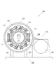
図1〜図3は、本発明による缶ビール冷却装置の全体構造を説明するための図である。図1は正面図を示し、図2は側面図を示し、図3は平面図を示している。 1-3 is a figure for demonstrating the whole structure of the canned beer cooling device by this invention. 1 shows a front view, FIG. 2 shows a side view, and FIG. 3 shows a plan view.
図1及び図2に示すように、本発明による缶ビール冷却装置100は、温度調節部110と、回転駆動部120とを備える。なお、簡単のため、図3では、温度調節部110は省略してある。
As shown in FIGS. 1 and 2, the canned
温度調節部110は、缶ビール101を保持して、缶ビール101の温度を調節(本実施形態では、冷却)するものである。図1及び図2に示すように、温度調節部110は、温度調節ユニット111と、温度調節ユニット保持部112とを備える。
The temperature adjusting
温度調節ユニット111は、缶ビール101の側面に当接して、缶ビール101の温度を調節(本実施形態では、冷却)するものである。図2に示すように、温度調節部110は、複数(本実施形態では、6つ)の温度調節ユニット111を備えている。なお、簡単のため、図1では、一つの温度調節ユニット111のみを示している。後述するように、各温度調節ユニット111は、熱電変換モジュール(ペルチェモジュール)を備えており、熱電変換モジュールに一定方向の電流を流すことによって、缶ビール101を冷却する。
The
温度調節ユニット保持部112は、複数の温度調節ユニット111を、缶ビール101の周囲に配置されるように保持するものである。後述するように、温度調節部110は、複数(本実施形態では、2つ)の温度調節ユニット保持部112を備えているが、図1では、そのうちの1つのみが見えている。
The temperature control
温度調節部110の構造の更なる詳細については後述する。
Further details of the structure of the
回転駆動部120は、温度調節部110を回転させるものであり、温度調節部110を回転させることによって、温度調節部110と共に、温度調節部110によって保持された缶ビール101を回転させるものである。図1〜図3に示すように、回転駆動部120は、温度調節部保持部121と、連結部材122と、回転シャフト123と、軸受部124と、従動プーリ125と,ベルト126と、駆動プーリ127と、減速機付きモータ128とを備える。また、回転シャフト123の中央部付近には、ロータリージョイント131と、スリップリング132とが装着されている。
The
温度調節部保持部121は、温度調節部110を保持する部材であって、背の低い有底円筒状の形状を有し、開口部分に、温度調節部110の一方の温度調節ユニット保持部112を収容した状態で、温度調節部110(温度調節ユニット保持部112)と連結される。また、温度調節部保持部121の底部の中央には、回転シャフト123の一端を挿入するための孔が形成されている。
The temperature adjustment
連結部材122は、温度調節部保持部121と回転シャフト123とを連結する部材である。温度調節部保持部121と回転シャフト123とは、連結部材122によって連結されることで、一体となって回転する。
The connecting
回転シャフト123は、温度調節部保持部121を回転させる軸部材であって、長手方向に延びる貫通孔141が形成された中空軸となっている。当該貫通孔141内には、温度調節ユニット111内の熱電変換モジュールへ電力を供給するための配線が通ることとなる。すなわち、熱電変換モジュールと、スリップリング132とを接続する配線が通ることとなる。更に、回転シャフト123の一方(図1における右側)の端面には、一定の深さを有する小さな縦穴142が複数個(本実施形態では、12個)、前記貫通孔141の回りに形成される。そして、回転シャフト123の側面のロータリージョイント131が装着される付近には、前記縦穴142のそれぞれと連通する横孔が形成されている。これらの横孔及び縦穴142並びにロータリージョイント131を介して、温度調節ユニット111への冷却液(冷却媒体)の供給及び温度調節ユニット111からの冷却液の回収が行われる。
The rotating
軸受部124は、回転シャフト123を回転可能に支持する部材であって、ボールベアリングと、ボールベアリングを保持するベアリングホルダとから構成される。図1に示すように、回転駆動部120は、軸受部124を2つ備えており、2つの軸受部124は、回転シャフト123の両端部付近に配置されている。各軸受部124は、ベース部150に立設された一対の脚部151に取り付けられて、ベース部150に固定されている。
The
従動プーリ125は、回転シャフト123を回転させるための部材であって、回転シャフト123の一方の端部付近に装着(固定)される。駆動プーリ127は、減速機付きモータ128の回転軸(出力シャフト)に装着(固定)される部材であって、減速機付きモータ128の回転軸と一体となって回転するものである。ベルト126は、従動プーリ125と駆動プーリ127とに巻き掛けられて、駆動プーリ127の回転を、従動プーリ125へ伝達するものである。すなわち、駆動プーリ127、ベルト126及び従動プーリ125を介して、減速機付きモータ128の回転力が、回転シャフト123に伝達されることになる。減速機付きモータ128は、駆動プーリ127、ベルト126及び従動プーリ125を介して、回転シャフト123を回転駆動するものである。なお、簡単のため、図1では、ベルト126、駆動プーリ127及び減速機付きモータ128は省略してある。
The driven
ロータリージョイント131は、温度調節部110に対して、放熱用の冷却液を供給するとともに、温度調節部110で使用された冷却液を、温度調節部110から回収するためのものであって、ロータリージョイント131を利用することにより、温度調節部110を回転させた状態においても、温度調節部110に対して、外部から冷却液を供給等することが可能となる。なお、前述したように、ロータリージョイント131は、回転シャフト123に形成された横孔及び縦穴142を介して、各温度調節ユニット111との間で冷却液の供給及び回収を行う。すなわち、簡単のため、図示は省略してあるが、各温度調節ユニット111と、回転シャフト123の一方の端面に形成された縦穴142とは、例えば、チューブ及び継手を介して適宜接続されており、各温度調節ユニット111への冷却液の供給及び各温度調節ユニット111からの冷却液の回収が可能なようになっている。前述したように、本実施形態では、縦穴142は12個形成されており、各縦穴142は、6つある温度調節ユニット111それぞれの供給用及び回収用のそれぞれに利用される(6×2=12)。
The rotary joint 131 is used to supply the heat-dissipating coolant to the
スリップリング132は、温度調節部110に対して、電力を供給するためのものであって、スリップリング132を利用することにより、温度調節部110を回転させた状態においても、温度調節部110に対して、外部から電力を供給することが可能になる。前述したように、スリップリング132と各温度調節ユニット111(熱電変換モジュール)との間の配線は、回転シャフト123内の空洞141を介して行われる。
The
次に、温度調節部110の構造について説明する。
Next, the structure of the
図4及び図5は、温度調節部110の構造を説明するための図である。図4は正面図を示し、図5は側面図を示す。なお、簡単のため、図4でも、一つの温度調節ユニット111のみを示している。
4 and 5 are diagrams for explaining the structure of the
前述したように、温度調節部110は、温度調節ユニット111と、温度調節ユニット保持部112とを備えている。図5に示すように、温度調節部110は、複数(具体的には、6つ)の温度調節ユニット111a〜111fを備えており、複数の温度調節ユニット111a〜111f全体で、缶ビール101の側面のほぼ全域を覆うようにしている。温度調節ユニット保持部112は、複数の温度調節ユニット111がこのような位置に配置されるよう、複数の温度調節ユニット111を保持している。図4に示すように、温度調節部110は、複数(具体的には、2つ)の温度調節ユニット保持部112を備えており、缶ビール101をセットした際に、各温度調節ユニット保持部112が、缶ビール1の端部(上端部又は下端部)付近に位置するように配置される。図5に示すように、温度調節ユニット保持部112は、円板状の部材の中央に正六角形状の孔が形成されたリング状の部材であって、その内周面(正六角形の各辺)に、温度調節ユニット111が固定される。
As described above, the
次に、温度調節ユニット111の構造について説明する。複数の温度調節ユニット111a〜111fの構造は、基本的に同一である。但し、6つの温度調節ユニット111のうち5つの温度調節ユニット111a〜111e(以下、可動温度調節ユニットということがある)は、温度調節ユニット保持部112に対して、進退(前後動)可能に構成されるのに対して、ひとつの温度調節ユニット111f(以下、固定温度調節ユニットということがある)は、進退(前後動)しないように構成される点で異なる。
Next, the structure of the
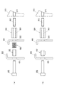
図6は、温度調節ユニット111の構造を説明するための図である。同図(a)は、可動温度調節ユニット111a〜111eの構造を示し、同図(b)は、固定温度調節ユニット111fの構造を示している。
FIG. 6 is a diagram for explaining the structure of the
同図に示すように、温度調節ユニット111は、伝熱ブロック610と、熱電変換モジュール620と、液冷ブロック630と、プッシャ640と、ホルダ650とを備える。
As shown in the figure, the
伝熱ブロック610は、缶ビールの側面に当接すると共に、熱電変換モジュール620の一方の面(本実施形態では、吸熱面)に接触して熱を伝達する伝熱部材であって、例えば、熱伝導性の高い金属(例えば、アルミニウム)によって構成される。伝熱ブロック610の缶ビールの側面に当接する側の面は、缶ビールの側面に密接するように、缶ビールの側面の形状に適合した形状に形成される。本実施形態では、6つの伝熱ブロック610で缶ビールの側面のほぼ全域を覆うようにしているので、各伝熱ブロック610は、缶ビールの周方向のほぼ1/6の領域を覆うように構成される。なお、伝熱ブロック610と、熱電変換モジュール620とは、例えば、熱伝導性の高い接着剤で接着されて一体をなす。
The
熱電変換モジュール620は、缶ビールの温度を調節(本実施形態では、冷却)するために、伝熱ブロック610の温度を調節(本実施形態では、冷却)する温度調節手段(冷却手段)であって、伝熱ブロック610と、液冷ブロック630との間に挟持される。熱電変換モジュール620の構造については後述する。
The
液冷ブロック630は、熱電変換モジュール620の他方の面(本実施形態では、放熱面)に接触して熱を伝達(放熱)する伝熱部材(放熱部材)であって、例えば、熱伝導性の高い金属(例えば、アルミニウム)によって構成される。液冷ブロック630は、概ね背の低い四角柱状の形状を有しており、その内部に、冷却液を通過させるための液路が形成されている。液路は、熱電変換モジュール620の放熱面と平行に蛇行するよう形成されており、供給口となる一方の継手から供給された冷却液が、排出口となる他方の継手に向かって、蛇行しながら流れることによって、熱電変換モジュール620の放熱面の熱が効果的に奪われることになる。液冷ブロック630の構造については後述する。
The
プッシャ640は、細長い平板状の部材の短手方向の両端部分を直角に曲げて、断面がコの字状になるように形成されたものである。プッシャ640は、スタッド660を介して伝熱ブロック610と一体をなすように接合(ねじ留め)されている。なお、スタッド660とは、中央部にねじ孔が形成された六角柱状の部材である。
The
ホルダ650は、プッシャ640を保持する部材であって、プッシャ640同様、細長い平板状の部材の短手方向の両端部分を直角に曲げて、断面がコの字状になるように形成されたものである。ホルダ650は、コの字の開口側をプッシャ640の方に向けた状態で、温度調節ユニット保持部112に取り付けられる。
The
また、同図に示すように、液冷ブロック630とプッシャ640との間には、付勢手段として、ばね(より具体的には、皿ばね)670が配置されており、皿ばね670の付勢力によって、液冷ブロック630が、熱電変換モジュール620に対して押しつけられるようになっている。なお、液冷ブロック630と熱電変換モジュール620とが接する面には、熱伝導性を高めるため、例えば、熱伝導性に優れた半固形状の物質であるサーマルグリースが塗布される。
Further, as shown in the figure, a spring (more specifically, a disc spring) 670 is disposed as an urging means between the
ここまで説明した構造は、6つの温度調節ユニット111すべてに共通する構造である。以下、可動温度調節ユニット111a〜111eと、固定温度調節ユニット111fとで異なる点について説明する。
The structure described so far is a structure common to all six
同図(a)に示すように、可動温度調節ユニット111a〜111eでは、プッシャ640とホルダ650との間に、付勢手段として、ばね(より具体的には、圧縮コイルばね)680が配置されており、圧縮コイルばね680によって、プッシャ640とホルダ650とは、互いに離れる方向に付勢されている。なお、圧縮コイルばね680は、ねじ690の軸部(ねじ部)が挿入される円筒状の部材である可動用カラー691の外周に装着されている。
As shown in FIG. 5A, in the movable
一方、同図(b)に示すように、固定温度調節ユニット111fでは、プッシャ640とホルダ650との間には、固定用カラー692が配置されており、当該固定用カラー692を介して、プッシャ640とホルダ650とが、ねじ690によって固定されている。
On the other hand, as shown in FIG. 5B, in the fixed
図7は、温度調節ユニット111における、各構成要素の連結関係を説明するための図である。同図(a)は、可動温度調節ユニット111a〜111eにおける連結関係を示し、同図(b)は、固定温度調節ユニット111fにおける連結関係を示している。
FIG. 7 is a diagram for explaining the connection relationship of each component in the
同図(a)に示すように、可動温度調節ユニット111a〜111eにおいては、まず、伝熱ブロック610とスタッド660とが、ねじ693によって連結される。更に、軸部に可動用カラー691を挿入したねじ690が、ホルダ650に形成された孔651及びプッシャ640に形成された孔641を介して、スタッド660に形成されたねじ孔661にねじ込まれることによって、プッシャ640とスタッド660とが連結される。その結果、伝熱ブロック610と、スタッド660と、プッシャ640と、カラー691と、ねじ690とは、一体をなすよう連結されることになる。なお、前述したように、可動用カラー691の外周には、圧縮コイルばね680が装着されて、プッシャ640とホルダ650とを互いに離れる方向に付勢する。また、同図(a)に示すように、可動用カラー691の径は、プッシャ640に形成された孔641の径よりは大きいが、ホルダ650に形成された孔651の径よりは小さいので、例えば、ホルダ650が固定された状態で、伝熱ブロック610に対して、同図の右から左に向かって外力が作用した場合、伝熱ブロック610と一体をなす可動用カラー691の左端部は、ホルダ650に形成された孔651を通過して、左側に突出することになる。
As shown in FIG. 5A, in the movable
一方、同図(b)に示すように、固定温度調節ユニット111fにおいても、可動温度調節ユニット111a〜111eと同様に、まず、伝熱ブロック610とスタッド660とが、ねじ693によって連結される。更に、固定温度調節ユニット111fでは、ねじ690が、ホルダ650に形成された孔651、固定用カラー692及びプッシャ640に形成された孔641を介して、スタッド660に形成されたねじ孔661にねじ込まれることによって、ホルダ650とプッシャ640とスタッド660とが連結される。同図(b)に示すように、固定用カラー692は、大径及び小径の円柱状部材を連結して、その中央にねじ690の軸部を通す孔を形成したような形状を有しており、更に、小径部の径は、ホルダ650に形成された孔651を通過可能である一方で、大径部の径は、プッシャ640に形成された孔641及びホルダ650に形成された孔651のいずれをも通過できないように形成されている。その結果、伝熱ブロック610と、スタッド660と、プッシャ640と、固定用カラー692と、ホルダ650と、ねじ690とは、一体をなすよう連結されることになる。
On the other hand, as shown in FIG. 5B, also in the fixed
図8は、可動温度調節ユニット111a〜111eの進退動作を説明するための図である。
FIG. 8 is a diagram for explaining the advance / retreat operation of the movable
可動温度調節ユニット111a〜111eにおいては、伝熱ブロック610に対して、外力が作用していない場合、圧縮コイルばね680の付勢力によって、ホルダ650から離れる方向(同図における右方向)に、プッシャ640が押され、同図(a)に示すように、プッシャ640と(可動用カラー691を介して)一体をなすねじ690の頭部がホルダ650に当接した状態で静止することになる。
In the movable
一方、同図(a)に示した状態において、伝熱ブロック610に対して、同図の右から左に向かって外力が作用した場合、スタッド660を介して、プッシャ640が、圧縮コイルばね680の付勢力に逆らって、ホルダ650に近づく方向(同図における左方向)に押され、同図(b)に示すように、プッシャ640の直角に曲げられた端部が、ホルダ650に当接した状態で静止することになる。この際、プッシャ640と一体をなす可動用カラー691及びねじ690は、同図(b)に示すように、同図(a)の状態に比べて、左側に突出することになる。
On the other hand, when an external force is applied to the heat transfer block 610 from the right to the left in the drawing (a) in the state shown in the figure (a), the
以上説明したように、可動温度調節ユニット111a〜111eにおいては、ホルダ650に対して、伝熱ブロック610(並びに伝熱ブロック610と一体をなす熱電変換モジュール620、液冷ブロック630及びプッシャ640)が進退(前後動)可能に構成される。
As described above, in the movable
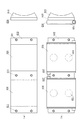
図9〜図11は、温度調節ユニット111における各構成要素の位置関係を説明するための図である。
9-11 is a figure for demonstrating the positional relationship of each component in the
図9(a)に示すように、本実施形態では、ひとつの伝熱ブロック610に対して、2つの熱電変換モジュール620を設けており、2つの熱電変換モジュール620は、それぞれ、伝熱ブロック610の長手方向の両端及び中央に形成されたねじ孔611の間に配置される。前述したように、伝熱ブロック610と熱電変換モジュール620とは、例えば、熱伝導性の高い接着剤で接着されて一体をなしている。また、2つの熱電変換モジュール620は、電気的には直列に接続される。
As shown in FIG. 9A, in the present embodiment, two
更に、同図(b)に示すように、各熱電変換モジュール620に対しては、液冷ブロック630が用意されており、前述したように、熱電変換モジュール620と液冷ブロック630は、熱伝導性を高めるため、例えば、サーマルグリースを介して、熱的に接触している。また、2つの液冷ブロック630は、一本の流路を形成するように、継手637及びチューブ(不図示)を介して直列に連結される。なお、同図(b)に示すように、液冷ブロック630の熱電変換モジュール620と接する面とは反対側の面には、後述する皿ばねホルダ671が嵌め込まれる浅い穴631が形成されている。
Further, as shown in FIG. 5B, a
更に、図10(a)に示すように、各液冷ブロック630に対しては、2つの皿ばねホルダ671が用意されている。皿ばねホルダ671は、円板状の部材(円板部)672の中央に円柱状の部材(円柱部)673を連結したような形状を有しており、円板部672が液冷ブロック630に形成された穴631に嵌め込まれ、円柱部673に皿ばねが装着されて、皿ばねの付勢力によって、液冷ブロック630を熱電変換モジュール620に対して押しつけるものである。
Furthermore, as shown in FIG. 10A, two
更に、同図(b)に示すように、各皿ばねホルダ671の円柱部673に皿ばね670を装着した状態で、各皿ばねホルダ671の円柱部673が、プッシャ640に形成された孔642に挿入されるように、プッシャ640が配置される。すなわち、各皿ばねホルダ671は、プッシャ640に形成された孔642に、円柱部673が保持された状態で、皿ばね670の付勢力によって、円板部672を液冷ブロック630に対して押しつけることになる。なお、このとき、伝熱ブロック610に形成されたねじ孔611の位置と、プッシャ640に形成された孔641の位置があうようになっている。
Further, as shown in FIG. 5B, in the state where the
更に、図11(a)に示すように、プッシャ640を覆うように、ホルダ650が配置される。この際、プッシャ640に形成された孔641と、ホルダ650に形成された孔651の位置があうように配置される。なお、同図(a)に示すように、ホルダ650には、更に、ホルダ650を温度調節ユニット保持部112に固定するためのねじ孔652が形成されている。すなわち、同図(b)に示すように、当該ねじ孔652を介して、ホルダ650が温度調節ユニット保持部112に固定されることによって、温度調節ユニット111全体が、温度調節ユニット保持部112に保持されることになる。
Furthermore, as shown in FIG. 11A, a
次に、熱電変換モジュール620の構造について説明する。
Next, the structure of the
図12は、熱電変換モジュール620の構造を説明するための図である。
FIG. 12 is a diagram for explaining the structure of the
同図に示すように、熱電変換モジュール620は、板状に並べられた複数のπ型熱電素子621(n型半導体素子622及びp型半導体素子623の一端を金属電極624で接合したもの)によって構成されており、複数のπ型熱電素子621は、金属電極625によって、電気的には直列に、熱的には並列に接続されている。同図に示した例では、矢印の方向(π型熱電素子のn側からp側へ向かう方向)に直流電流を流すと、上面側(π型熱電素子のnp接合側)で吸熱が行われ、底面側で放熱が行われることになる。また、上面及び底面には、それぞれ、絶縁基板626(例えば、セラミック基板)が接合されており、吸熱面及び放熱面を形成している。なお、同図では、上面側の絶縁基板は省略してある。
As shown in the figure, the
次に、液冷ブロック630の構造について説明する。
Next, the structure of the
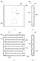
図13は、液冷ブロック630の構造を説明するための図である。同図(a)は正面図を示し、同図(b)は側面図を示し、同図(c)は断面図を示している。また、同図(d)は、後述するエンドブロックの底面図を示している。
FIG. 13 is a view for explaining the structure of the
同図に示すように、液冷ブロック630は、一つの本体ブロック632と、二つのエンドブロック633とによって構成されている。本体ブロック632及びエンドブロック633は、一体となって、冷却液を流すための液路を形成する部材である。
As shown in the figure, the
同図に示すように、本体ブロック632は、概ね背の低い四角柱状の形状を有し、一方(同図における左側)の端面から他方(同図における右側)の端面に向かって延びる複数(同図の例では、9つ)の貫通孔634が形成されている。当該貫通孔634が、冷却液が流れる液路の一部を構成することになる。
As shown in the figure, the
同図に示すように、エンドブロック633は、概ね細長い四角柱状の形状を有し、長手方向の端部に貫通孔635が形成されている。当該貫通孔635は、継手が接続されて、冷却液の供給口又は排出口を構成することになる。また、エンドブロック633は、本体ブロック632と接合された際、隣接する貫通孔634同士を連通して、一本の液路を形成するよう、本体ブロック632と対向する面に、複数(同図の例では、4つ)の長穴(凹部)636が形成されている。2つのエンドブロック633は、同図に示すように、貫通孔635が対角の位置に来るように配置されて、本体ブロック632と接合される。
As shown in the figure, the
以上のような構造を有する本体ブロック632とエンドブロック633とを組み付けることにより、供給口となる継手から、排出口となる継手に向かって、蛇行しながら進む液路が、液冷ブロック630内に形成されることになる。すなわち、一方のエンドブロック633に形成された貫通孔635から導入された冷却液は、2つのエンドブロック633の間を、エンドブロック633にぶつかるたびに、180°向きを変えて流れることになり、交互に180°逆向きに流れるように蛇行しながら、他方のエンドブロック633に形成された貫通孔635に向かって流れることになる。
By assembling the
また、同図(a)に示すように、液冷ブロック630は、プッシャ640と対向する面に、円状の浅い穴631が形成されている。当該穴631は、前述したように、皿ばねホルダ671が嵌り込む穴である。液冷ブロック630は、皿ばねホルダ671に装着された皿ばね670によって、プッシャ640に対して、熱電変換モジュール620の方向に押されることになる。すなわち、液冷ブロック630は、皿ばね670の付勢力によって、熱電変換モジュール620に対して押しつけられることになる。
Further, as shown in FIG. 5A, the
次に、以上のような構成を有する缶ビール冷却装置100の動作について説明する。
Next, operation | movement of the can
まず、図1及び図2に示すように、冷却対象となる缶ビール101を缶ビール冷却装置100にセットする。すなわち、温度調節部110の一方側(図1における右側)から、缶ビール101を押し込むことで、図1に示す位置に、缶ビール101をセットする。缶ビール101がセットされていない状態では、6つの温度調節ユニット111(伝熱ブロック610)で形成される円柱状領域の径は、缶ビール101の径よりやや小さくなるように構成されている。このような状態において、缶ビール101を押し込もうとすると、温度調節ユニット111(伝熱ブロック610)が外側に向かって押されることになる。そうすると、可動温度調節ユニット111a〜111eについては、プッシャ640とホルダ650との間に配置された圧縮コイルばね680が縮み、温度調節ユニット111(伝熱ブロック610)が少し、温度調節ユニット保持部112(ホルダ650)の方へ後退するので、缶ビール101のセットは容易に行える。この際、固定温度調節ユニット111fについては動かないので、缶ビール101は、固定温度調節ユニット111fを基準に、所定の位置にセットされることになる。また、缶ビール101が、図1及び図2に示すように、所定の位置にセットされた状態では、可動温度調節ユニット111a〜111eについては、プッシャ640とホルダ650との間に配置された圧縮コイルばね680の付勢力によって、プッシャ640が缶ビール101方向に押されることとなり、プッシャ640と一体をなす伝熱ブロック610が缶ビール101の側面に押しつけられることになる。その結果、伝熱ブロック610と缶ビール101との密接度が高まり、両者間の熱伝導性が向上して、冷却効率を向上させることができる。
First, as shown in FIGS. 1 and 2, the canned
缶ビール101のセットが完了すると、次に、温度調節部110及び回転駆動部120をそれぞれ動作させる。まず、温度調節部110(温度調節ユニット111)を動作させることによって、伝熱ブロック610に当接する缶ビール101を冷却する。すなわち、熱電変換モジュール620に直流電流を流すことによって、伝熱ブロック610及び缶ビール101を冷却する。
When the setting of the canned
また、同時に、回転駆動部120を動作させることによって、温度調節部110を、缶ビール101と共に回転させる。すなわち、減速機付きモータ128を動作させることによって、駆動プーリ127、ベルト126及び従動プーリ125を介して、回転シャフト123を回転させ、回転シャフト123に固定された温度調節部保持部121を回転させる。その結果、温度調節部110が、缶ビール101と共に回転することとなる。
At the same time, the
温度調節部110を動作させて、セットした缶ビール101を冷却しつつ、缶ビール101を温度調節部110と共に回転させることにより、温度調節部110による冷却によって缶ビール101の内周面付近に温度境界層が発生するのを抑制することが可能となり、冷却効率を向上させることができる。
The
以上のようにして、缶ビール冷却装置100を一定時間動作させると、冷却対象となる缶ビール101が、所望の温度まで、急速に冷却されることになる。
As described above, when the canned
上述した缶ビール冷却装置100によれば、缶ビール101の周囲を覆うように配置された複数の温度調節ユニット111を同時に動作させているので、缶ビール101を急速に冷却することが可能となる。
According to the above-described canned
更に、温度調節部110を缶ビール101と共に回転させているので、缶ビール101の内周面付近に温度境界層が発生するのを抑制することが可能となり、冷却効率を向上させて、缶ビール101をより速く冷却することが可能となる。
Furthermore, since the
また、上述した実施形態では、熱電変換モジュール620の放熱に、空冷方式ではなく、液冷方式を採用しているので、装置(温度調節部110)をコンパクトに構成することが可能となる。
Further, in the above-described embodiment, since the liquid cooling method is adopted for the heat radiation of the
以上、本発明の実施形態について説明してきたが、当然のことながら、本発明の実施形態は上記のものに限られない。例えば、上述した実施形態においては、6つの温度調節ユニット111によって、缶ビールの側面のほぼ全域を覆うようにしていたが、必要とされる冷却性能に応じて、温度調節ユニットの数を変えたり、缶ビールの側面の一部を覆うようにしたりすることもできる。例えば、前述した温度調節ユニット111を3つ使って、3つの温度調節ユニット111を等間隔に、缶ビールの周囲に配置するようにすることで、缶ビールの側面のほぼ1/2の領域を覆うようにすることが考えられる。
As mentioned above, although embodiment of this invention has been described, it cannot be overemphasized that embodiment of this invention is not restricted above. For example, in the above-described embodiment, six
また、上述した実施形態では、缶ビールを冷却する場合について説明したが、もちろん、本発明を、缶ジュースその他の容器入り飲料の冷却に利用することもできるし、冷却する場合だけでなく、加温する場合に利用することも考えられる。例えば、熱電変換モジュールに流す電流の向きを逆にすれば、吸熱面と放熱面とが逆になるので、上述した構成のまま、容器入り飲料を加温することが可能になる。 In the above-described embodiment, the case where canned beer is cooled has been described. Of course, the present invention can also be used for cooling canned juice and other beverages contained in containers. It may be used when warming. For example, if the direction of the current flowing through the thermoelectric conversion module is reversed, the heat absorption surface and the heat dissipation surface are reversed, so that the beverage in a container can be heated with the above-described configuration.
100 缶ビール冷却装置
110 温度調節部
111 温度調節ユニット
111a〜111e 可動温度調節ユニット
111f 固定温度調節ユニット
112 温度調節ユニット保持部
120 回転駆動部
121 温度調節部保持部
122 連結部材
123 回転シャフト
124 軸受部
125 従動プーリ
126 ベルト
127 駆動プーリ
128 減速機付きモータ
131 ロータリージョイント
132 スリップリング
141 貫通孔
142 縦穴
150 ベース部
151 脚部
610 伝熱ブロック
611 ねじ孔
620 熱電変換モジュール
621 π型熱電素子
622 n型半導体素子
623 p型半導体素子
624,625 金属電極
626 絶縁基板
630 液冷ブロック
631 穴
632 本体ブロック
633 エンドブロック
634,635 貫通孔
636 長孔(凹部)
637 継手
640 プッシャ
641,642 孔
650 ホルダ
651 孔
652 ねじ孔
660 スタッド
661 ねじ孔
670 皿ばね
671 皿ばねホルダ
672 円板部
673 円柱部
680 圧縮コイルばね
690 ねじ
691 可動用カラー
692 固定用カラー
693 ねじ
DESCRIPTION OF
Claims (9)
前記温度調節部を回転させる回転駆動部と
を備え、
前記温度調節部は、前記容器入り飲料の側面に当接する温度調節ユニットを備える
ことを特徴とする容器入り飲料温度調節装置。 Holding a beverage in a container and adjusting the temperature of the beverage in the container;
A rotation drive unit that rotates the temperature adjustment unit,
The temperature adjusting unit includes a temperature adjusting unit that contacts a side surface of the container-containing beverage.
ことを特徴とする請求項1に記載の容器入り飲料温度調節装置。 The container temperature adjusting device according to claim 1, wherein the temperature adjusting unit includes a plurality of the temperature adjusting units.
ことを特徴とする請求項2に記載の容器入り飲料温度調節装置。 The said temperature control unit is arrange | positioned around the said drink in a container, The drink temperature adjustment apparatus in a container of Claim 2 characterized by the above-mentioned.
ことを特徴とする請求項3に記載の容器入り飲料温度調節装置。 The said temperature control unit covers the whole region of the side surface of the said container-containing drink, The container-containing drink temperature control apparatus of Claim 3 characterized by the above-mentioned.
ことを特徴とする請求項2〜4のいずれか一項に記載の容器入り飲料温度調節装置。 The said temperature control part hold | maintains the said beverage with a container when the said several temperature control unit contact | abuts the side surface of the said beverage with a container, The Claims 2-4 characterized by the above-mentioned. Container drink temperature control device.
前記容器入り飲料の側面に当接する伝熱部材と、
一方の面が、前記伝熱部材と熱的に接触する熱電変換モジュールと
を備える
ことを特徴とする請求項1〜5のいずれか一項に記載の容器入り飲料温度調節装置。 The temperature control unit includes:
A heat transfer member in contact with the side surface of the beverage containing the container;
One surface is provided with the thermoelectric conversion module which contacts the said heat-transfer member thermally, The drink temperature adjustment apparatus with a container as described in any one of Claims 1-5 characterized by the above-mentioned.
前記伝熱部材を進退可能に保持するホルダ
を更に備えることを特徴とする請求項6に記載の容器入り飲料温度調節装置。 The temperature control unit includes:
The container-containing beverage temperature adjusting device according to claim 6, further comprising a holder that holds the heat transfer member so as to be movable back and forth.
前記伝熱部材を、前記容器入り飲料の方向に付勢する付勢手段
を更に備えることを特徴とする請求項7に記載の容器入り飲料温度調節装置。 The temperature control unit includes:
8. The container-containing beverage temperature adjusting device according to claim 7, further comprising urging means for urging the heat transfer member in a direction of the container-containing beverage.
前記熱電変換モジュールの他方の面と、熱的に接触する液冷部材
を更に備えることを特徴とする請求項6〜8のいずれか一項に記載の容器入り飲料温度調節装置。 The temperature control unit includes:
The beverage temperature adjusting device in a container according to any one of claims 6 to 8, further comprising a liquid cooling member that is in thermal contact with the other surface of the thermoelectric conversion module.
Priority Applications (5)
| Application Number | Priority Date | Filing Date | Title |
|---|---|---|---|
| JP2008238891A JP5033743B2 (en) | 2008-09-18 | 2008-09-18 | Container temperature control device |
| PCT/JP2009/065930 WO2010032689A1 (en) | 2008-09-18 | 2009-09-11 | Packaged beverage temperature adjustment device |
| CN200980137061XA CN102159909B (en) | 2008-09-18 | 2009-09-11 | Packaged beverage temperature adjustment device |
| EP09814534.5A EP2327944B1 (en) | 2008-09-18 | 2009-09-11 | Packaged beverage temperature adjustment device |
| US13/050,764 US8919138B2 (en) | 2008-09-18 | 2011-03-17 | Packaged beverage temperature adjustment apparatus |
Applications Claiming Priority (1)
| Application Number | Priority Date | Filing Date | Title |
|---|---|---|---|
| JP2008238891A JP5033743B2 (en) | 2008-09-18 | 2008-09-18 | Container temperature control device |
Publications (2)
| Publication Number | Publication Date |
|---|---|
| JP2010071539A true JP2010071539A (en) | 2010-04-02 |
| JP5033743B2 JP5033743B2 (en) | 2012-09-26 |
Family
ID=42039513
Family Applications (1)
| Application Number | Title | Priority Date | Filing Date |
|---|---|---|---|
| JP2008238891A Active JP5033743B2 (en) | 2008-09-18 | 2008-09-18 | Container temperature control device |
Country Status (5)
| Country | Link |
|---|---|
| US (1) | US8919138B2 (en) |
| EP (1) | EP2327944B1 (en) |
| JP (1) | JP5033743B2 (en) |
| CN (1) | CN102159909B (en) |
| WO (1) | WO2010032689A1 (en) |
Families Citing this family (14)
| Publication number | Priority date | Publication date | Assignee | Title |
|---|---|---|---|---|
| WO2013112710A1 (en) * | 2012-01-25 | 2013-08-01 | Alphabet Energy, Inc. | Modular thermoelectric units for heat recovery systems and methods thereof |
| WO2014008423A2 (en) | 2012-07-06 | 2014-01-09 | Gentherm Incorporated | Systems and methods for cooling inductive charging assemblies |
| CN105121224A (en) * | 2013-03-15 | 2015-12-02 | 金瑟姆股份公司 | Thermally-conditioned beverage holders and bins |
| CN104764290A (en) * | 2014-01-04 | 2015-07-08 | 黄雄浩 | Rapid refrigerating device for beverage |
| EP3098546A1 (en) * | 2015-05-25 | 2016-11-30 | Vestel Beyaz Esya Sanayi Ve Ticaret A.S. | A chilling system |
| EP3124881A1 (en) | 2015-07-28 | 2017-02-01 | Siemens Aktiengesellschaft | Peltier air dehumidifer for installation in a container |
| CA3047606C (en) * | 2017-03-03 | 2023-02-14 | Legacy US, LLC | Modularized beverage holder for actively cooling beverages and method for performing the same |
| CA3095760A1 (en) | 2018-04-19 | 2019-10-24 | Ember Technologies, Inc. | Portable cooler with active temperature control |
| JP6603364B1 (en) * | 2018-05-16 | 2019-11-06 | 株式会社テックスイージー | Container temperature control device |
| WO2020146394A2 (en) | 2019-01-11 | 2020-07-16 | Ember Technologies, Inc. | Portable cooler with active temperature control |
| US11668508B2 (en) | 2019-06-25 | 2023-06-06 | Ember Technologies, Inc. | Portable cooler |
| CA3143365A1 (en) | 2019-06-25 | 2020-12-30 | Ember Technologies, Inc. | Portable cooler |
| US11162716B2 (en) | 2019-06-25 | 2021-11-02 | Ember Technologies, Inc. | Portable cooler |
| RU203556U1 (en) * | 2020-02-29 | 2021-04-12 | Ирина Владимировна Павлова | THERMOELECTRIC GAS DRYER TWD |
Citations (3)
| Publication number | Priority date | Publication date | Assignee | Title |
|---|---|---|---|---|
| JP2003114080A (en) * | 2001-07-30 | 2003-04-18 | Tekkusu Iijii:Kk | Thermoelectric conversion device and manufacturing method therefor |
| JP2005331159A (en) * | 2004-05-19 | 2005-12-02 | Kmj:Kk | Drink quick cooling device |
| US20080098767A1 (en) * | 2001-02-12 | 2008-05-01 | Philip Molfese | Liquid Cooler Apparatus |
Family Cites Families (19)
| Publication number | Priority date | Publication date | Assignee | Title |
|---|---|---|---|---|
| US4164851A (en) * | 1977-12-19 | 1979-08-21 | Bryant Jon A | Beverage container cooler |
| GB2168798B (en) * | 1984-12-19 | 1989-05-17 | Charles Raymond Micallef | A method and apparatus for cooling beverage in a bottle |
| US5282368A (en) * | 1993-05-17 | 1994-02-01 | Ordoukhanian Raymond D | Beverage cooling device |
| US5584183A (en) * | 1994-02-18 | 1996-12-17 | Solid State Cooling Systems | Thermoelectric heat exchanger |
| JPH11201613A (en) * | 1998-01-09 | 1999-07-30 | Yamaha Corp | Electronic cooling drink cooler |
| US6606866B2 (en) * | 1998-05-12 | 2003-08-19 | Amerigon Inc. | Thermoelectric heat exchanger |
| US6035660A (en) * | 1998-07-27 | 2000-03-14 | W.C. Linden, Inc. | Refrigerated beverage mug |
| US6272867B1 (en) * | 1999-09-22 | 2001-08-14 | The Coca-Cola Company | Apparatus using stirling cooler system and methods of use |
| EP1320298B8 (en) | 2000-08-18 | 2007-10-10 | FBD Partnership LP | Frozen beverage machine |
| US6474093B1 (en) * | 2000-10-23 | 2002-11-05 | Cosmo Tech Development, Inc. | Expanding barrel system for cooling beverages |
| EP1364175B1 (en) * | 2001-03-01 | 2009-08-12 | Revolutionary Cooling Systems, Inc. | Rapid fluid cooling and heating device and method |
| US6701718B1 (en) * | 2001-04-18 | 2004-03-09 | University Of South Florida | Heat exchanging apparatus for handling and transporting vessels |
| US6945069B2 (en) * | 2003-01-24 | 2005-09-20 | Lg Electronics Inc. | Quick cooling device |
| US7059137B2 (en) * | 2004-09-07 | 2006-06-13 | Childress William H | Portable thermoelectric cooling and heating device |
| US7650757B2 (en) * | 2005-01-24 | 2010-01-26 | Delphi Technologies, Inc. | Thermoelectric heat transfer system |
| US7178343B2 (en) * | 2005-03-23 | 2007-02-20 | Innovative Displayworks, Inc. | Compact thermoelectric wine cooler and humidor |
| EP1984208B1 (en) * | 2006-01-30 | 2012-02-29 | Amerigon, Inc. | Cooling system for container in a vehicle |
| PL1821053T3 (en) * | 2006-01-31 | 2016-04-29 | Electrolux Home Products Corp Nv | Rapid chilling apparatus for beverages and method for controlling the same |
| WO2009055066A1 (en) * | 2007-10-25 | 2009-04-30 | Paradise Smoothies, Inc. | Apparatus for mixing, cooling, and dispensing a containerized beverage |
-
2008
- 2008-09-18 JP JP2008238891A patent/JP5033743B2/en active Active
-
2009
- 2009-09-11 WO PCT/JP2009/065930 patent/WO2010032689A1/en active Application Filing
- 2009-09-11 EP EP09814534.5A patent/EP2327944B1/en active Active
- 2009-09-11 CN CN200980137061XA patent/CN102159909B/en active Active
-
2011
- 2011-03-17 US US13/050,764 patent/US8919138B2/en active Active
Patent Citations (3)
| Publication number | Priority date | Publication date | Assignee | Title |
|---|---|---|---|---|
| US20080098767A1 (en) * | 2001-02-12 | 2008-05-01 | Philip Molfese | Liquid Cooler Apparatus |
| JP2003114080A (en) * | 2001-07-30 | 2003-04-18 | Tekkusu Iijii:Kk | Thermoelectric conversion device and manufacturing method therefor |
| JP2005331159A (en) * | 2004-05-19 | 2005-12-02 | Kmj:Kk | Drink quick cooling device |
Also Published As
| Publication number | Publication date |
|---|---|
| JP5033743B2 (en) | 2012-09-26 |
| EP2327944B1 (en) | 2014-10-29 |
| EP2327944A1 (en) | 2011-06-01 |
| EP2327944A4 (en) | 2013-04-10 |
| WO2010032689A1 (en) | 2010-03-25 |
| CN102159909B (en) | 2013-11-27 |
| CN102159909A (en) | 2011-08-17 |
| US8919138B2 (en) | 2014-12-30 |
| US20110167839A1 (en) | 2011-07-14 |
Similar Documents
| Publication | Publication Date | Title |
|---|---|---|
| JP5033743B2 (en) | Container temperature control device | |
| JP2008528912A (en) | Counterflow thermoelectric configuration using heat transfer fluid in a closed cycle | |
| JP2005519256A (en) | Thermoelectric transient cooling and transient heating system | |
| KR20040067652A (en) | Ice maker | |
| US7825324B2 (en) | Spreading thermoelectric coolers | |
| JP2009152440A (en) | Temperature regulator for heating element | |
| US20180087812A1 (en) | Single beverage container thermo electric cooler | |
| US6351952B1 (en) | Interruptible thermal bridge system | |
| KR101756376B1 (en) | cup holder device composed of selection type for cooling and heating | |
| JP3154096U (en) | Container temperature control device | |
| JP2924369B2 (en) | Heat pump device | |
| JP4497171B2 (en) | Beverage quick cooler | |
| JP2008106958A (en) | Heat exchanger | |
| JP6054661B2 (en) | Cooling device, cooling system, and cooling heating system | |
| JPH08186205A (en) | Temperature control device and method | |
| WO2018003009A1 (en) | Refrigerating/heating device, and analysis device | |
| JP2007097872A (en) | Freezing method of straw tube and its freezing device | |
| KR970002797B1 (en) | Cooler for a canned beverage | |
| US20070226891A1 (en) | Spa including thermoelectric module for providing cooling of beverages | |
| JP2010164277A (en) | Liquid temperature adjustment device | |
| JP2012069872A (en) | Temperature maintaining device for packaged beverage | |
| KR200208302Y1 (en) | Cooling and heating equipment of a beverage | |
| JP3172502B2 (en) | Thermoelectric converters such as coolers, heaters, temperature regulators, and generators using Peltier modules, coolers using Peltier modules, heaters using Peltier modules, and generators using Peltier modules | |
| KR200444959Y1 (en) | Table type cooling apparatus of using thermoelectric module | |
| JPH11201613A (en) | Electronic cooling drink cooler |
Legal Events
| Date | Code | Title | Description |
|---|---|---|---|
| A621 | Written request for application examination |
Free format text: JAPANESE INTERMEDIATE CODE: A621 Effective date: 20110630 |
|
| A131 | Notification of reasons for refusal |
Free format text: JAPANESE INTERMEDIATE CODE: A131 Effective date: 20120417 |
|
| A521 | Request for written amendment filed |
Free format text: JAPANESE INTERMEDIATE CODE: A523 Effective date: 20120528 |
|
| TRDD | Decision of grant or rejection written | ||
| A01 | Written decision to grant a patent or to grant a registration (utility model) |
Free format text: JAPANESE INTERMEDIATE CODE: A01 Effective date: 20120626 |
|
| A01 | Written decision to grant a patent or to grant a registration (utility model) |
Free format text: JAPANESE INTERMEDIATE CODE: A01 |
|
| A61 | First payment of annual fees (during grant procedure) |
Free format text: JAPANESE INTERMEDIATE CODE: A61 Effective date: 20120702 |
|
| R150 | Certificate of patent or registration of utility model |
Ref document number: 5033743 Country of ref document: JP Free format text: JAPANESE INTERMEDIATE CODE: R150 Free format text: JAPANESE INTERMEDIATE CODE: R150 |
|
| FPAY | Renewal fee payment (event date is renewal date of database) |
Free format text: PAYMENT UNTIL: 20150706 Year of fee payment: 3 |
|
| R250 | Receipt of annual fees |
Free format text: JAPANESE INTERMEDIATE CODE: R250 |
|
| R250 | Receipt of annual fees |
Free format text: JAPANESE INTERMEDIATE CODE: R250 |
|
| R250 | Receipt of annual fees |
Free format text: JAPANESE INTERMEDIATE CODE: R250 |
|
| R250 | Receipt of annual fees |
Free format text: JAPANESE INTERMEDIATE CODE: R250 |
|
| R250 | Receipt of annual fees |
Free format text: JAPANESE INTERMEDIATE CODE: R250 |