US20080098767A1 - Liquid Cooler Apparatus - Google Patents
Liquid Cooler Apparatus Download PDFInfo
- Publication number
- US20080098767A1 US20080098767A1 US11/673,654 US67365407A US2008098767A1 US 20080098767 A1 US20080098767 A1 US 20080098767A1 US 67365407 A US67365407 A US 67365407A US 2008098767 A1 US2008098767 A1 US 2008098767A1
- Authority
- US
- United States
- Prior art keywords
- container
- block
- freezer
- heatsink
- interior
- Prior art date
- Legal status (The legal status is an assumption and is not a legal conclusion. Google has not performed a legal analysis and makes no representation as to the accuracy of the status listed.)
- Granted
Links
Images


Classifications
-
- F—MECHANICAL ENGINEERING; LIGHTING; HEATING; WEAPONS; BLASTING
- F25—REFRIGERATION OR COOLING; COMBINED HEATING AND REFRIGERATION SYSTEMS; HEAT PUMP SYSTEMS; MANUFACTURE OR STORAGE OF ICE; LIQUEFACTION SOLIDIFICATION OF GASES
- F25D—REFRIGERATORS; COLD ROOMS; ICE-BOXES; COOLING OR FREEZING APPARATUS NOT OTHERWISE PROVIDED FOR
- F25D31/00—Other cooling or freezing apparatus
- F25D31/006—Other cooling or freezing apparatus specially adapted for cooling receptacles, e.g. tanks
- F25D31/007—Bottles or cans
-
- F—MECHANICAL ENGINEERING; LIGHTING; HEATING; WEAPONS; BLASTING
- F25—REFRIGERATION OR COOLING; COMBINED HEATING AND REFRIGERATION SYSTEMS; HEAT PUMP SYSTEMS; MANUFACTURE OR STORAGE OF ICE; LIQUEFACTION SOLIDIFICATION OF GASES
- F25D—REFRIGERATORS; COLD ROOMS; ICE-BOXES; COOLING OR FREEZING APPARATUS NOT OTHERWISE PROVIDED FOR
- F25D23/00—General constructional features
- F25D23/02—Doors; Covers
- F25D23/04—Doors; Covers with special compartments, e.g. butter conditioners
-
- F—MECHANICAL ENGINEERING; LIGHTING; HEATING; WEAPONS; BLASTING
- F25—REFRIGERATION OR COOLING; COMBINED HEATING AND REFRIGERATION SYSTEMS; HEAT PUMP SYSTEMS; MANUFACTURE OR STORAGE OF ICE; LIQUEFACTION SOLIDIFICATION OF GASES
- F25D—REFRIGERATORS; COLD ROOMS; ICE-BOXES; COOLING OR FREEZING APPARATUS NOT OTHERWISE PROVIDED FOR
- F25D23/00—General constructional features
- F25D23/12—Arrangements of compartments additional to cooling compartments; Combinations of refrigerators with other equipment, e.g. stove
- F25D23/126—Water cooler
-
- F—MECHANICAL ENGINEERING; LIGHTING; HEATING; WEAPONS; BLASTING
- F25—REFRIGERATION OR COOLING; COMBINED HEATING AND REFRIGERATION SYSTEMS; HEAT PUMP SYSTEMS; MANUFACTURE OR STORAGE OF ICE; LIQUEFACTION SOLIDIFICATION OF GASES
- F25D—REFRIGERATORS; COLD ROOMS; ICE-BOXES; COOLING OR FREEZING APPARATUS NOT OTHERWISE PROVIDED FOR
- F25D2331/00—Details or arrangements of other cooling or freezing apparatus not provided for in other groups of this subclass
- F25D2331/80—Type of cooled receptacles
- F25D2331/805—Cans
-
- F—MECHANICAL ENGINEERING; LIGHTING; HEATING; WEAPONS; BLASTING
- F25—REFRIGERATION OR COOLING; COMBINED HEATING AND REFRIGERATION SYSTEMS; HEAT PUMP SYSTEMS; MANUFACTURE OR STORAGE OF ICE; LIQUEFACTION SOLIDIFICATION OF GASES
- F25D—REFRIGERATORS; COLD ROOMS; ICE-BOXES; COOLING OR FREEZING APPARATUS NOT OTHERWISE PROVIDED FOR
- F25D3/00—Devices using other cold materials; Devices using cold-storage bodies
- F25D3/02—Devices using other cold materials; Devices using cold-storage bodies using ice, e.g. ice-boxes
- F25D3/06—Movable containers
- F25D3/08—Movable containers portable, i.e. adapted to be carried personally
Definitions
- This invention relates generally to cooling devices, and more specifically to a cooling device that will rapidly cool the contents of a liquid container.
- Rotating a container of liquid about its longitudinal axis while the container is within a bucket of ice can cool the container of liquid. Furthermore, cooling is effected more quickly as the speed of rotation is increased.
- holding and rotating a container while it is disposed in ice can cause the container to tear or fracture due to the sharp edges which may be present on the ice.
- manually handling the container may be awkward.
- Still other container coolers are designed for either bottles or cans exclusively, and not for both.
- U.S. Pat. No. 2,216,762 issued to Bolas discloses a mechanism to rotate a bottle of wine inserted into an ice bucket and is specifically limited to bottles.
- U.S. Pat. No. 3,316,734, issued to Crane discloses an apparatus for cooling canned liquids and is specifically limited to cans.
- a liquid cooler is provided herein.
- the liquid cooler includes a housing and at least two heatsinks attached with the housing.
- the heatsinks each includes a top wall with an inwardly facing wall, a bottom wall with an inner surface, interior sidewalls and an interior lower wall.
- the inner surface is formed to surround and contact a portion of an outer surface of a container.
- the inwardly facing wall, the interior sidewalls, and the interior lower wall define a cavity.
- the interior lower wall of the cavity includes at least one heat fin.
- An outer covering is included and surrounds the heatsinks.
- a method of rotation is provided to rotate the heatsinks and the outer covering.
- the liquid cooler in another aspect of the invention, includes a housing and a block attached with the housing.
- the block has an inner surface that defines a space.
- the block is configured so that the space is able to receive a container, and a method of rotation is provided to rotate the block.
- the liquid cooler in another aspect of the invention, includes a housing and at least one heatsink attached with the housing.
- the heatsink includes a flexible membrane and interior sidewalls.
- the membrane is formed to surround and contact a portion of an outer surface of a container.
- the interior sidewall and the membrane define a cavity.
- a cooling substance is provided and contained within the cavity.
- the liquid cooler also includes an outer covering that is attached with the housing and surrounds the heatsink. A method of rotation is provided to rotate the heatsink and the outer covering.
- the liquid cooler includes a housing and at least one heatsink attached with said housing.
- the heatsink has a top wall with an inwardly facing wall, a bottom wall with an inner surface formed to surround and contact a portion of an outer surface of the container, interior sidewalls and an interior lower wall.
- the inwardly facing wall, interior sidewalls, and interior lower wall define a cavity.
- the interior lower wall of the cavity includes at least one heat fin.
- the liquid container further includes an outer covering attached with the housing that surrounds the heatsink, a pushbutton for rotating the heatsink and the outer covering, and an ejector button for removing the container from the heatsink.
- the invention also embodies a method of rapidly chilling liquids within containers.
- the method includes providing a liquid cooler having a housing, at least one cold heatsink, and a container receiver.
- a 12-ounce container is placed into the container receiver.
- the container receiver is rotated, and the container is cooled from approximately 80 degrees F. to approximately 40 degrees F. in less than one minute.
- the container is then removed from the container receiver.
- the invention also embodies a method of promoting the sale of liquid coolers. At least one liquid cooler having a container receiver is distributed. The liquid cooler is then incorporated into a device. A container is placed into the container receiver. The container receiver is rotated, and the container is cooled from approximately 80 degrees F. to approximately 40 degrees F. in less than one minute. The container is then removed from the container receiver.
- FIG. 1 is a side view of an embodiment
- FIG. 2 is a side view of an embodiment of FIG. 1 with the heatsinks removed;
- FIG. 3 is a front sectional view of an embodiment taken along the line A-A of FIG. 1 ;
- FIG. 4 is a side view of another embodiment showing a block
- FIG. 5 is a front sectional view of an embodiment taken along the line B-B of FIG. 4 ;
- FIG. 6 is a side view of an embodiment of FIG. 1 showing an ejecting member
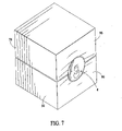
- FIG. 7 is a perspective view of two heatsinks and a container with the heatsinks each having a membrane;
- FIG. 8 is a side view of an embodiment of the liquid cooler incorporated into a recreational product, with the sidewall of the recreational product removed;
- FIG. 9 is a top view of an embodiment of the liquid cooler incorporated into a recreational product, with the liquid cooler configured to face upwardly;
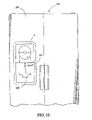
- FIG. 10 is a front view of the liquid cooler incorporated into the freezer door of a refrigerator-freezer
- FIGS. 1-3 generally illustrate an embodiment of the liquid cooler 2 .
- a novel liquid cooler 2 to cool liquid in a container 4 is described below.
- the container 4 has a top side 6 , a bottom side 8 , and a peripheral boundary 10 connecting the top side 6 and bottom side 8 .
- the peripheral boundary 10 of the container 4 includes an outer surface 14 .
- the container 4 may be made of glass, aluminum, plastic, or any other type of material typically used to hold liquid.
- the container 4 may be a commonly available product, such as a can or bottle of beer, soda, or juice.
- the container 4 may also be a commonly available cleaning agent, chemical, or solvent.
- the liquid cooler 2 has a base 16 .
- the base 16 includes a top surface 20 and a sidewall 22 having a first surface 24 and a second surface 26 .
- a bottom face 28 of the sidewall 22 is attached with the top surface 20 of the base 16 .
- Protruding from a through-going opening 30 in the first surface 24 and second surface 26 of the sidewall 22 is a shaft 32 .
- the shaft 32 has a first end 34 that protrudes from the portion of the opening 30 in the first surface 24 , and a second end 36 that protrudes from the portion of the opening 30 in the second surface 26 .
- a rotating connector 38 having a front side 40 and a rear side 42 is attached with the first end 34 of the shaft 32 .
- the rotating connector 38 is attached with the first end 34 of the shaft 32 , preferably by having screws 44 passing through the front side 40 and the rear side 42 of the rotating connector 38 and fastening the rear side 42 of the rotating connector 38 to the first end 34 of the shaft 32 .
- a rotating mechanism 46 having an inner side 48 and an outer side 50 is attached with the second end 36 of the shaft 32 .
- the rotating mechanism 46 is a conventional bearing or gear assembly.
- a handle 52 is connected with the outer side 50 of the rotating mechanism 46 , and provides for direct rotation of the shaft 32 .
- Two heatsinks 58 each having a top side 60 , a bottom side 62 , and a front side 63 are connected with the front side 40 of the rotating connector 38 .
- the heatsinks 58 preferably are removably connected with the front side 40 of the rotating connector 38 , but they can also be affixed to the rotating connector 38 .
- the heatsink 58 is made from a conductive material, such as aluminum. However, in other embodiments other types of materials may also be used, such as plastics.
- the bottom side 62 of the heatsink 58 has an inner portion 64 .
- the inner portion 64 is formed to be substantially adjacent to and in contact with the peripheral boundary 10 of the container 4 .
- the heatsinks 58 are oriented to form a container receiver 66 that surrounds a container 4 when a container 4 is placed therein.
- an outer covering may be attached with the rotating connector so that it surrounds the heatsinks.
- the heatsinks are oriented in the outer covering to form the container receiver described above, and are removable with respect to the outer sheet. Insulation may be placed between the heatsinks and the outer covering.
- An inwardly facing wall 68 of the top side 60 , a pair of interior sidewalls 70 , and an interior bottom wall 72 define a cavity 74 within the heatsink 58 .
- the cavity 74 holds a cooling substance, such as ice or conventional gel or “cold packs.”
- the interior bottom wall 72 of the cavity 74 is formed to be adapted to the shape of the bottom side 62 of the heatsink 58 .
- the interior bottom wall 72 of the cavity 74 preferably is defined by a series of heat fins 76 which have been formed in the interior bottom wall 72 .
- other embodiments of the invention can have the heatsink without an interior bottom wall adapted to include heat fins.
- the top side 60 of the heatsink 58 is removable, and allows the cooling substance to be removed from and placed into the cavity 74 .
- the top side may be non-removable with respect to the heatsink.
- a drain hole may be put in the heatsink to allow the cooling substance to be removed from and placed into the cavity.
- the heatsinks may be utilized without a cooling substance.
- the operation of the liquid cooler is as follows:
- the heatsinks 58 with or without a cooling substance, preferably are removed from a freezer where they have been stored.
- the heatsinks 58 are then connected with the front side 40 of the rotating connector 38 .
- the heatsinks will be placed within the outer covering and will be oriented to form the container receiver 66 .
- a container 4 is placed into the container receiver 66 so that the container 4 lies along its longitudinal axis in the container receiver 66 .
- the inner portion 64 of the bottom side 62 of the heatsink 58 should contact the outer surface 14 of the container 4 .
- the clearance 61 will also increase the force exerted on the container 4 , allowing for greater conductivity between the cooling substance in the cavity 74 and the liquid in the container 4 .
- the handle 52 is then used to rotate the heatsinks 58 and the container 4 within the container receiver 66 . While the container 4 is being rotated, different portions of the liquid within the container 4 are circulated towards the peripheral boundary 10 of the container 4 .
- the inner portion 64 of the heatsink 58 cooled by the cooling substance within the cavity 74 of the heatsink 58 , will cool the liquid in the container 4 as it circulates towards the peripheral boundary 10 .
- the heat fins 76 in the cavity 74 allow for a high level of conductivity between the cooling substance in the cavity 74 and the liquid in the container 4 .
- heatsinks there may be a different number of heatsinks. More than two heatsinks may be connected with the front side of the rotating connector, with the heatsinks oriented to form a container receiver as previously described. Alternatively, one heatsink may be used.
- FIGS. 4 and 5 there may be one block 98 attached with the rotating connector 38 . Passing through the block 98 is a cutout 100 adapted to surround and receive a container 4 .
- An interior upper wall 102 , an interior lower wall 104 , a pair of interior sidewalls 106 , and an inside wall 108 , formed to surround the cutout 100 define a cavity 110 in the block.
- the cavity 110 in the block 98 may hold a cooling substance.
- Heat fins as described above, may be used to define the inside wall 108 of the cavity 110 , but are not necessary.
- another embodiment of the liquid cooler 2 also incorporates an ejecting member 80 for removing the container 4 from the container receiver 66 .
- the ejecting member 80 has a first end 82 and a second end 84 , and preferably incorporates a spring 86 so that the ejecting member 80 is spring-loaded.
- the first end 82 of the ejecting member 80 protrudes from a cutout 88 in the handle 52 .
- the second end 84 of the ejecting member 80 passes through an opening 90 in the shaft 32 , and protrudes from a cutout 92 in the rotating connector 38 .
- Operation of the ejecting member 80 is as follows: once a container 4 has been cooled as described above, the first end 82 of the ejecting member 80 is depressed. While the first end 82 of the ejecting member 80 is depressed, the second end 84 will contact the container 4 and dislodge the container 4 from the container receiver 66 so that a portion of the container 4 protrudes from the container receiver 66 . The first end 82 is then released, and the spring 86 returns the ejecting member 80 to its non-depressed position. The container 4 may then be removed from the container receiver 66 .
- an ejected member may still be incorporated into the liquid cooler.
- FIG. 7 another embodiment of the invention incorporates a flexible membrane 96 for use with liquid coolers that utilize a cooling substance.
- the membrane 96 allows for expansion of the cooling substance.
- a membrane 96 is used in lieu of the front face of the heatsink 58 , although in other embodiments the membrane may be used in lieu of the front and bottom faces of the heatsink.
- the membrane 96 allows for thermal variations in the cooling substance, allowing the cooling substance to expand, and thereby preventing the heatsink from cracking.
- the membrane may be any suitable material having sufficient strength such as, by way of example, latex, plastic, or urethanes.
- a pressure relief valve may be used instead of a membrane.
- the pressure relief valve is a one-way valve located on the heatsink that allows gases to exit from the heatsink but which retains liquid. The pressure relief valve would prevent expansion of the cooling substance, and, as with the membrane, would prevent the heatsink from cracking.
- a handle may be connected with one of the heatsinks.
- a motor assembly may be connected with the rotating connector, allowing for motorized rotation of the liquid cooler.
- a conventional electrical cord inserted into an electrical outlet, may supply power to the motor assembly.
- Rotation may also be accomplished using battery power, such as through the use of a push button on the liquid cooler or by plugging the liquid cooler into a battery source such as a cigarette lighter in an automobile.
- rotation may be accomplished using solar power.
- FIG. 8 another embodiment of the invention allows the liquid cooler 2 to be incorporated into a recreational product 112 such as a transportable picnic cooler.
- a recreational product 112 such as a transportable picnic cooler.
- the second end 36 of the shaft 32 may be incorporated into a first side 114 of a wall 116 of the recreational product 112 so that the second end 36 protrudes from a second side 118 of the wall 116 of the recreational product 112 .
- the handle 52 may then be attached with the second end 36 of the shaft 32 .
- Operation of the liquid cooler 2 is as described above.
- FIG. 9 shows an additional embodiment of the liquid cooler 2 incorporated into a recreational product 112 .
- the liquid cooler 2 is oriented so that the container receiver 66 faces upwardly and preferably is operated via a pushbutton 125 on a heatsink 58 .
- any of the rotational methods described above may be used.
- FIG. 10 illustrates the liquid cooler 2 incorporated in the door of a refrigerator-freezer 136 .
- Conventional refrigerator-freezers often will have a water dispenser and an icemaker located on a freezer door.
- the liquid cooler 2 may be incorporated into freezer door 134 with a water dispenser 130 and an icemaker 132 .
- the liquid cooler may also be incorporated into a freezer door alone.
- the advantages of the above-described embodiments of the invention are numerous.
- the heatsinks removably attached with the rotating connector, they can easily be stored in a freezer without taking up space. When used to cool a container, they may be removed from the freezer for use with the liquid cooler.
- the liquid cooler allows for the rapid cooling of containers, refrigerated space need not be wasted storing a plurality of cans. This is especially useful for smaller refrigerators, such as those commonly found in college dormitories.
- Another advantage of the present embodiments is not having the cooling substance in direct contact with the container.
- the container will not become wet or soiled, and therefore will be easier to handle.
Landscapes
- Engineering & Computer Science (AREA)
- Chemical & Material Sciences (AREA)
- Combustion & Propulsion (AREA)
- Physics & Mathematics (AREA)
- Mechanical Engineering (AREA)
- Thermal Sciences (AREA)
- General Engineering & Computer Science (AREA)
- Packages (AREA)
Abstract
A liquid cooler is disclosed that includes a housing and at least two heatsinks attached with the housing. The heatsinks each include a top wall with an inwardly facing wall, a bottom wall with an inner surface, interior sidewalls and an interior lower wall. The inner surface is formed to surround and contact a portion of an outer surface of a container. The inwardly facing wall, the interior sidewalls, and the interior lower wall define a cavity. The interior lower wall of the cavity includes at least one heat fin. An outer covering is included and surrounds the heatsink. A method of rotation is provided to rotate the heatsink and the outer covering.
Description
- This application is a continuation (divisional) of co-pending U.S. patent application Ser. No. 10/073,821, filed Feb. 11, 2002, which claims the benefit of priority to U.S. Provisional Application No. 60/268,172, filed Feb. 12, 2001. This divisional application incorporates by reference and claims the benefit of priority to both prior applications.
- This invention relates generally to cooling devices, and more specifically to a cooling device that will rapidly cool the contents of a liquid container.
- Rotating a container of liquid about its longitudinal axis while the container is within a bucket of ice can cool the container of liquid. Furthermore, cooling is effected more quickly as the speed of rotation is increased. However, holding and rotating a container while it is disposed in ice can cause the container to tear or fracture due to the sharp edges which may be present on the ice. Furthermore, manually handling the container may be awkward.
- This situation has prompted others to manufacture devices to effect the rapid chilling of beverages in containers. Some of these devices cool beverages by rotating a container that is in direct contact with a cold substance. However, this will often cause the container to get soiled and be more difficult to handle. Additionally, some of these beverage coolers are awkward to handle and difficult to store.
- Still other container coolers are designed for either bottles or cans exclusively, and not for both. For example, U.S. Pat. No. 2,216,762, issued to Bolas, discloses a mechanism to rotate a bottle of wine inserted into an ice bucket and is specifically limited to bottles. U.S. Pat. No. 3,316,734, issued to Crane, discloses an apparatus for cooling canned liquids and is specifically limited to cans.
- A liquid cooler is provided herein. The liquid cooler includes a housing and at least two heatsinks attached with the housing. The heatsinks each includes a top wall with an inwardly facing wall, a bottom wall with an inner surface, interior sidewalls and an interior lower wall. The inner surface is formed to surround and contact a portion of an outer surface of a container. The inwardly facing wall, the interior sidewalls, and the interior lower wall define a cavity. The interior lower wall of the cavity includes at least one heat fin. An outer covering is included and surrounds the heatsinks. A method of rotation is provided to rotate the heatsinks and the outer covering.
- In another aspect of the invention, the liquid cooler includes a housing and a block attached with the housing. The block has an inner surface that defines a space. The block is configured so that the space is able to receive a container, and a method of rotation is provided to rotate the block.
- In another aspect of the invention, the liquid cooler includes a housing and at least one heatsink attached with the housing. The heatsink includes a flexible membrane and interior sidewalls. The membrane is formed to surround and contact a portion of an outer surface of a container. The interior sidewall and the membrane define a cavity. A cooling substance is provided and contained within the cavity. The liquid cooler also includes an outer covering that is attached with the housing and surrounds the heatsink. A method of rotation is provided to rotate the heatsink and the outer covering.
- Another aspect of the invention provides a refrigerator-freezer having a freezer door including a liquid cooler for cooling a container. The liquid cooler includes a housing and at least one heatsink attached with said housing. The heatsink has a top wall with an inwardly facing wall, a bottom wall with an inner surface formed to surround and contact a portion of an outer surface of the container, interior sidewalls and an interior lower wall. The inwardly facing wall, interior sidewalls, and interior lower wall define a cavity. The interior lower wall of the cavity includes at least one heat fin. The liquid container further includes an outer covering attached with the housing that surrounds the heatsink, a pushbutton for rotating the heatsink and the outer covering, and an ejector button for removing the container from the heatsink.
- The invention also embodies a method of rapidly chilling liquids within containers. The method includes providing a liquid cooler having a housing, at least one cold heatsink, and a container receiver. A 12-ounce container is placed into the container receiver. The container receiver is rotated, and the container is cooled from approximately 80 degrees F. to approximately 40 degrees F. in less than one minute. The container is then removed from the container receiver.
- The invention also embodies a method of promoting the sale of liquid coolers. At least one liquid cooler having a container receiver is distributed. The liquid cooler is then incorporated into a device. A container is placed into the container receiver. The container receiver is rotated, and the container is cooled from approximately 80 degrees F. to approximately 40 degrees F. in less than one minute. The container is then removed from the container receiver.
- The foregoing and other features and advantages of the invention will become further apparent from the following detailed description of the embodiments, read in conjunction with the accompanying drawings.
-
FIG. 1 is a side view of an embodiment; -
FIG. 2 is a side view of an embodiment ofFIG. 1 with the heatsinks removed; -
FIG. 3 is a front sectional view of an embodiment taken along the line A-A ofFIG. 1 ; -
FIG. 4 is a side view of another embodiment showing a block; -
FIG. 5 is a front sectional view of an embodiment taken along the line B-B ofFIG. 4 ; -
FIG. 6 is a side view of an embodiment ofFIG. 1 showing an ejecting member; -
FIG. 7 is a perspective view of two heatsinks and a container with the heatsinks each having a membrane; -
FIG. 8 is a side view of an embodiment of the liquid cooler incorporated into a recreational product, with the sidewall of the recreational product removed; -
FIG. 9 is a top view of an embodiment of the liquid cooler incorporated into a recreational product, with the liquid cooler configured to face upwardly; and -
FIG. 10 is a front view of the liquid cooler incorporated into the freezer door of a refrigerator-freezer; -
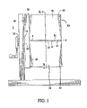
FIGS. 1-3 generally illustrate an embodiment of theliquid cooler 2. Anovel liquid cooler 2 to cool liquid in acontainer 4 is described below. Thecontainer 4 has atop side 6, abottom side 8, and aperipheral boundary 10 connecting thetop side 6 andbottom side 8. Theperipheral boundary 10 of thecontainer 4 includes anouter surface 14. Thecontainer 4 may be made of glass, aluminum, plastic, or any other type of material typically used to hold liquid. Thecontainer 4 may be a commonly available product, such as a can or bottle of beer, soda, or juice. By way of another example, thecontainer 4 may also be a commonly available cleaning agent, chemical, or solvent. - The
liquid cooler 2 has abase 16. Thebase 16 includes atop surface 20 and asidewall 22 having afirst surface 24 and asecond surface 26. Preferably, abottom face 28 of thesidewall 22 is attached with thetop surface 20 of thebase 16. Protruding from a through-goingopening 30 in thefirst surface 24 andsecond surface 26 of thesidewall 22 is ashaft 32. Theshaft 32 has afirst end 34 that protrudes from the portion of theopening 30 in thefirst surface 24, and asecond end 36 that protrudes from the portion of theopening 30 in thesecond surface 26. - A rotating
connector 38 having afront side 40 and arear side 42 is attached with thefirst end 34 of theshaft 32. The rotatingconnector 38 is attached with thefirst end 34 of theshaft 32, preferably by havingscrews 44 passing through thefront side 40 and therear side 42 of the rotatingconnector 38 and fastening therear side 42 of the rotatingconnector 38 to thefirst end 34 of theshaft 32. - A
rotating mechanism 46 having aninner side 48 and anouter side 50 is attached with thesecond end 36 of theshaft 32. Preferably, the rotatingmechanism 46 is a conventional bearing or gear assembly. Ahandle 52 is connected with theouter side 50 of therotating mechanism 46, and provides for direct rotation of theshaft 32. - Two
heatsinks 58, each having atop side 60, abottom side 62, and afront side 63 are connected with thefront side 40 of the rotatingconnector 38. Theheatsinks 58 preferably are removably connected with thefront side 40 of the rotatingconnector 38, but they can also be affixed to the rotatingconnector 38. Preferably, theheatsink 58 is made from a conductive material, such as aluminum. However, in other embodiments other types of materials may also be used, such as plastics. - The
bottom side 62 of theheatsink 58 has aninner portion 64. Theinner portion 64 is formed to be substantially adjacent to and in contact with theperipheral boundary 10 of thecontainer 4. When attached with the rotatingconnector 38, theheatsinks 58 are oriented to form acontainer receiver 66 that surrounds acontainer 4 when acontainer 4 is placed therein. - In other embodiments, an outer covering may be attached with the rotating connector so that it surrounds the heatsinks. The heatsinks are oriented in the outer covering to form the container receiver described above, and are removable with respect to the outer sheet. Insulation may be placed between the heatsinks and the outer covering.
- An inwardly facing
wall 68 of thetop side 60, a pair ofinterior sidewalls 70, and aninterior bottom wall 72 define acavity 74 within theheatsink 58. Thecavity 74 holds a cooling substance, such as ice or conventional gel or “cold packs.” Theinterior bottom wall 72 of thecavity 74 is formed to be adapted to the shape of thebottom side 62 of theheatsink 58. - Referring to
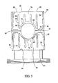
FIG. 3 , theinterior bottom wall 72 of thecavity 74 preferably is defined by a series ofheat fins 76 which have been formed in theinterior bottom wall 72. However, other embodiments of the invention can have the heatsink without an interior bottom wall adapted to include heat fins. - The
top side 60 of theheatsink 58 is removable, and allows the cooling substance to be removed from and placed into thecavity 74. However, in other embodiments, the top side may be non-removable with respect to the heatsink. In yet another embodiment of a heatsink with a non-removable top side, a drain hole may be put in the heatsink to allow the cooling substance to be removed from and placed into the cavity. Alternatively, the heatsinks may be utilized without a cooling substance. - The operation of the liquid cooler is as follows: The
heatsinks 58, with or without a cooling substance, preferably are removed from a freezer where they have been stored. Theheatsinks 58 are then connected with thefront side 40 of the rotatingconnector 38. For liquid coolers that use an outer covering, the heatsinks will be placed within the outer covering and will be oriented to form thecontainer receiver 66. Acontainer 4 is placed into thecontainer receiver 66 so that thecontainer 4 lies along its longitudinal axis in thecontainer receiver 66. - When the
container 4 is in thecontainer receiver 66, theinner portion 64 of thebottom side 62 of theheatsink 58 should contact theouter surface 14 of thecontainer 4. Preferably, however, there should be anominal clearance 61 between thebottom sides 62 of theheatsinks 58 so that they do not contact each other. While thisclearance 61 is not necessary for the operation of theliquid cooler 2, having thisclearance 61 will prevent interference between thecontainer 4 and theheatsinks 58. Theclearance 61 will also increase the force exerted on thecontainer 4, allowing for greater conductivity between the cooling substance in thecavity 74 and the liquid in thecontainer 4. - The
handle 52 is then used to rotate theheatsinks 58 and thecontainer 4 within thecontainer receiver 66. While thecontainer 4 is being rotated, different portions of the liquid within thecontainer 4 are circulated towards theperipheral boundary 10 of thecontainer 4. Theinner portion 64 of theheatsink 58, cooled by the cooling substance within thecavity 74 of theheatsink 58, will cool the liquid in thecontainer 4 as it circulates towards theperipheral boundary 10. Theheat fins 76 in thecavity 74 allow for a high level of conductivity between the cooling substance in thecavity 74 and the liquid in thecontainer 4. - Because different portions of the warm liquid are continuously being circulated towards the
peripheral boundary 10 of thecontainer 4, a large temperature gradient is maintained between the cooling substance in thecavity 74 and liquid in thecontainer 4. The large temperature gradient allows the liquid in thecontainer 4 to be cooled in less than one minute. - Once the liquid in the
container 4 is cooled, rotation is stopped and thecontainer 4 is removed from thecontainer receiver 66. - While the embodiments of the invention disclosed herein are presently considered to be preferred, various changes and modifications can be made without departing from the spirit and scope of the invention. For example, in other embodiments of the invention there may be a different number of heatsinks. More than two heatsinks may be connected with the front side of the rotating connector, with the heatsinks oriented to form a container receiver as previously described. Alternatively, one heatsink may be used.
- As shown in
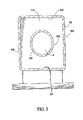
FIGS. 4 and 5 , in another embodiment there may be oneblock 98 attached with the rotatingconnector 38. Passing through theblock 98 is acutout 100 adapted to surround and receive acontainer 4. An interiorupper wall 102, an interiorlower wall 104, a pair ofinterior sidewalls 106, and aninside wall 108, formed to surround thecutout 100, define acavity 110 in the block. As with thecavity 74 in theheatsink 58 previously described, thecavity 110 in theblock 98 may hold a cooling substance. Heat fins, as described above, may be used to define theinside wall 108 of thecavity 110, but are not necessary. - As shown in
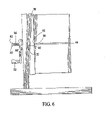
FIG. 6 , another embodiment of theliquid cooler 2 also incorporates an ejectingmember 80 for removing thecontainer 4 from thecontainer receiver 66. The ejectingmember 80 has afirst end 82 and asecond end 84, and preferably incorporates aspring 86 so that the ejectingmember 80 is spring-loaded. In a preferred embodiment, thefirst end 82 of the ejectingmember 80 protrudes from acutout 88 in thehandle 52. Thesecond end 84 of the ejectingmember 80 passes through anopening 90 in theshaft 32, and protrudes from acutout 92 in the rotatingconnector 38. - Operation of the ejecting
member 80 is as follows: once acontainer 4 has been cooled as described above, thefirst end 82 of the ejectingmember 80 is depressed. While thefirst end 82 of the ejectingmember 80 is depressed, thesecond end 84 will contact thecontainer 4 and dislodge thecontainer 4 from thecontainer receiver 66 so that a portion of thecontainer 4 protrudes from thecontainer receiver 66. Thefirst end 82 is then released, and thespring 86 returns the ejectingmember 80 to its non-depressed position. Thecontainer 4 may then be removed from thecontainer receiver 66. - Note that in additional embodiments that incorporate rotational devices other than a handle, described in more detail below, an ejected member may still be incorporated into the liquid cooler.
- Referring now to
FIG. 7 , another embodiment of the invention incorporates aflexible membrane 96 for use with liquid coolers that utilize a cooling substance. Themembrane 96 allows for expansion of the cooling substance. Preferably, amembrane 96 is used in lieu of the front face of theheatsink 58, although in other embodiments the membrane may be used in lieu of the front and bottom faces of the heatsink. Themembrane 96 allows for thermal variations in the cooling substance, allowing the cooling substance to expand, and thereby preventing the heatsink from cracking. As shown inFIG. 7 , when acontainer 4 is placed into thecontainer receiver 66, themembrane 96 will flex to conform to the shape of the container. The membrane may be any suitable material having sufficient strength such as, by way of example, latex, plastic, or urethanes. - In an alternative embodiment, a pressure relief valve may be used instead of a membrane. The pressure relief valve is a one-way valve located on the heatsink that allows gases to exit from the heatsink but which retains liquid. The pressure relief valve would prevent expansion of the cooling substance, and, as with the membrane, would prevent the heatsink from cracking.
- In other embodiments, different devices and configurations can be used to rotate the heatsinks. For example, instead of using a handle connected with a shaft to rotate the heatsinks, a handle may be connected with one of the heatsinks. Alternatively, a motor assembly may be connected with the rotating connector, allowing for motorized rotation of the liquid cooler. A conventional electrical cord, inserted into an electrical outlet, may supply power to the motor assembly. Rotation may also be accomplished using battery power, such as through the use of a push button on the liquid cooler or by plugging the liquid cooler into a battery source such as a cigarette lighter in an automobile. In yet additional embodiments, rotation may be accomplished using solar power.
- As shown in
FIG. 8 , another embodiment of the invention allows theliquid cooler 2 to be incorporated into arecreational product 112 such as a transportable picnic cooler. For example, instead of utilizing thebase 16, thesecond end 36 of theshaft 32 may be incorporated into afirst side 114 of awall 116 of therecreational product 112 so that thesecond end 36 protrudes from asecond side 118 of thewall 116 of therecreational product 112. Thehandle 52 may then be attached with thesecond end 36 of theshaft 32. Operation of theliquid cooler 2 is as described above.FIG. 9 shows an additional embodiment of theliquid cooler 2 incorporated into arecreational product 112. Theliquid cooler 2 is oriented so that thecontainer receiver 66 faces upwardly and preferably is operated via apushbutton 125 on aheatsink 58. However, any of the rotational methods described above may be used. -
FIG. 10 illustrates theliquid cooler 2 incorporated in the door of a refrigerator-freezer 136. Conventional refrigerator-freezers often will have a water dispenser and an icemaker located on a freezer door. As shown inFIG. 10 , theliquid cooler 2 may be incorporated intofreezer door 134 with awater dispenser 130 and anicemaker 132. Of course, the liquid cooler may also be incorporated into a freezer door alone. - The advantages of the above-described embodiments of the invention are numerous. For example, by having the heatsinks removably attached with the rotating connector, they can easily be stored in a freezer without taking up space. When used to cool a container, they may be removed from the freezer for use with the liquid cooler. Furthermore, because the liquid cooler allows for the rapid cooling of containers, refrigerated space need not be wasted storing a plurality of cans. This is especially useful for smaller refrigerators, such as those commonly found in college dormitories.
- Another advantage of the present embodiments is not having the cooling substance in direct contact with the container. The container will not become wet or soiled, and therefore will be easier to handle.
- The embodiments of the invention disclosed herein are presently considered to be preferred, various changes and modifications can be made without departing from the spirit and scope of the invention. The scope of the invention is indicated in the appended claims, and all changes that come within the meaning and range of equivalents are intended to be embraced therein.
Claims (20)
1. A refrigerator-freezer comprising: a freezer door including a liquid cooler for cooling a container, said liquid cooler having a housing, at least one heatsink attached with said housing, said heatsink having a top wall with an inwardly facing wall, a bottom wall with an inner surface formed to surround and contact a portion of an outer surface of said container, interior sidewalls and an interior lower wall, said inwardly facing wall, said interior sidewalls, and said interior lower wall defining a cavity, wherein said interior lower wall of said cavity includes at least one heat fin, said liquid container further including an outer covering attached with said housing that surrounds said heatsink, a pushbutton for rotating said heatsink and said outer covering, and an ejector button for removing said container from said heatsink.
2. The refrigerator-freezer of claim 1 , wherein said outer covering is insulated.
3. The refrigerator-freezer of claim 1 , wherein said block further comprises a conductive material.
4. The refrigerator-freezer of claim 3 , wherein said conductive material comprises aluminum.
5. The refrigerator-freezer of claim 1 , wherein said heatsink further comprises a plastic material.
6. The refrigerator-freezer of claim 1 , wherein said heatsink comprises a pressure relief valve.
7. An apparatus for rapidly cooling the liquid contents of a container, the apparatus comprising:
a block having an inner space configured to receive the container and to surround and contact a major portion of the outer surface of the container, the block being substantially comprised of a material having high thermal conductivity;
cooling means for reducing the temperature of the block, the cooling means having a housing connected to the block; and
rotating means connected to the housing for rotating the block and the container about the longitudinal axis of the container,
whereby the liquid contents of the container are rapidly cooled via heat transfer to the block when the block has been previously made cold.
8. The apparatus of claim 7 , wherein said block has at least one inner wall that is flexible so as to conform to containers having different shapes.
9. The apparatus of claim 8 , wherein said inner wall includes a flexible membrane comprised of a material selected from the group of latex, plastic, and urethane.
10. The apparatus of claim 7 , wherein said block includes an enclosed interior cavity adapted for containing a cooling substance.
11. The apparatus of claim 7 , wherein said block includes a plurality of heat fins protruding into the interior cavity.
12. The apparatus of claim 7 , wherein said rotating means includes an electric motor.
13. The apparatus of claim 7 , wherein said rotating means includes a handle configured for the user to manually rotate.
14. The apparatus of claim 7 , wherein said cooling means is a freezer.
15. The apparatus of claim 7 , wherein said cooling means is a portable cooler.
16. A freezer for rapidly chilling the liquid contents of a substantially cylindrically shaped beverage container having a first temperature, the freezer adapted to lower its interior temperature to a second temperature substantially below the first temperature, the freezer comprising:
an external wall having an outside surface accessible to a user and an inside surface disposed on the interior of the freezer;
a block having a substantially cylindrically shaped inner space configured to receive the beverage container and to surround and directly contact a major portion of the outer surface of the container, the block being substantially larger than the container and being substantially comprised of a conductive material;
mounting means for coupling the block to the external wall such that the majority of the block is disposed on the interior of the freezer and such that a beverage container can be placed into the inner space of the block from outside the freezer;
rotating means coupled to the mounting means for rotating the block and the container along the longitudinal axis of the container,
whereby upon placing the beverage container within the inner space of the block and rotating the block and the container for a period of time, the liquid contents of the beverage container are chilled via heat transfer from the beverage to the block.
17. The apparatus of claim 16 , wherein the inner surface of the inner space of the block includes a flexible membrane comprised of a material selected from the group of latex, plastic, and urethane.
18. The apparatus of claim 16 , wherein said rotating means includes an electric motor configured to continuously rotate the block and container.
19. The apparatus of claim 16 , wherein said block includes an enclosed interior cavity adapted for containing a cooling substance.
20. The apparatus of claim 16 , wherein the inner space of the block is configured to surround and contact substantially all of the outer surface of a cylindrically shaped 12 ounce beverage can.
Priority Applications (1)
| Application Number | Priority Date | Filing Date | Title |
|---|---|---|---|
| US11/673,654 US7497087B2 (en) | 2001-02-12 | 2007-02-12 | Liquid cooler apparatus |
Applications Claiming Priority (3)
| Application Number | Priority Date | Filing Date | Title |
|---|---|---|---|
| US26817201P | 2001-02-12 | 2001-02-12 | |
| US10/073,821 US7174723B2 (en) | 2001-02-12 | 2002-02-11 | Portable liquid cooler |
| US11/673,654 US7497087B2 (en) | 2001-02-12 | 2007-02-12 | Liquid cooler apparatus |
Related Parent Applications (1)
| Application Number | Title | Priority Date | Filing Date |
|---|---|---|---|
| US10/073,821 Division US7174723B2 (en) | 2001-02-12 | 2002-02-11 | Portable liquid cooler |
Publications (2)
| Publication Number | Publication Date |
|---|---|
| US20080098767A1 true US20080098767A1 (en) | 2008-05-01 |
| US7497087B2 US7497087B2 (en) | 2009-03-03 |
Family
ID=26754926
Family Applications (2)
| Application Number | Title | Priority Date | Filing Date |
|---|---|---|---|
| US10/073,821 Expired - Fee Related US7174723B2 (en) | 2001-02-12 | 2002-02-11 | Portable liquid cooler |
| US11/673,654 Expired - Fee Related US7497087B2 (en) | 2001-02-12 | 2007-02-12 | Liquid cooler apparatus |
Family Applications Before (1)
| Application Number | Title | Priority Date | Filing Date |
|---|---|---|---|
| US10/073,821 Expired - Fee Related US7174723B2 (en) | 2001-02-12 | 2002-02-11 | Portable liquid cooler |
Country Status (3)
| Country | Link |
|---|---|
| US (2) | US7174723B2 (en) |
| AU (1) | AU2002242154A1 (en) |
| WO (1) | WO2002065032A1 (en) |
Cited By (1)
| Publication number | Priority date | Publication date | Assignee | Title |
|---|---|---|---|---|
| JP2010071539A (en) * | 2008-09-18 | 2010-04-02 | Tekkusu Iijii:Kk | Canned beverage temperature adjusting device |
Families Citing this family (10)
| Publication number | Priority date | Publication date | Assignee | Title |
|---|---|---|---|---|
| US6974598B2 (en) * | 1999-05-14 | 2005-12-13 | Coors Worldwide Inc. | Method of cooling a beverage |
| US7785641B2 (en) * | 1998-05-15 | 2010-08-31 | Coors Brewing Company | Method of cooling a beverage |
| US6964177B2 (en) * | 2003-05-28 | 2005-11-15 | Lg Electronics Inc. | Refrigerator with icemaker |
| US20070131716A1 (en) * | 2004-05-29 | 2007-06-14 | Prabucki Robert W | Solar panel and water dispenser |
| US7182222B2 (en) * | 2004-05-29 | 2007-02-27 | Prabucki Robert W | Solar panel and water dispenser |
| US9080803B2 (en) * | 2012-02-10 | 2015-07-14 | Turbo Innovations, Llc | Method and device for rapidly cooling liquids |
| JP6054661B2 (en) * | 2012-07-17 | 2016-12-27 | サントリーホールディングス株式会社 | Cooling device, cooling system, and cooling heating system |
| USD735250S1 (en) | 2013-06-11 | 2015-07-28 | Turbo Innovations, Llc | Rapid fluid heat exchange device |
| EP3098546A1 (en) * | 2015-05-25 | 2016-11-30 | Vestel Beyaz Esya Sanayi Ve Ticaret A.S. | A chilling system |
| US10180274B2 (en) * | 2015-07-20 | 2019-01-15 | William J Jacob | Rapid cooling dock |
Citations (10)
| Publication number | Priority date | Publication date | Assignee | Title |
|---|---|---|---|---|
| US4164851A (en) * | 1977-12-19 | 1979-08-21 | Bryant Jon A | Beverage container cooler |
| US4549409A (en) * | 1985-03-21 | 1985-10-29 | Smith Jeffrey I | Apparatus for cooling beverage containers and the like |
| US4580405A (en) * | 1985-05-10 | 1986-04-08 | Cretzmeyer Iii Francis X | Beverage cooling device and method for using same |
| US5361604A (en) * | 1993-07-09 | 1994-11-08 | Pier Steven J | Beverage chilling receptacle |
| US5505054A (en) * | 1994-08-26 | 1996-04-09 | Loibl; Gregory H. | Rapid beverage cooling |
| US5845501A (en) * | 1994-09-22 | 1998-12-08 | Stonehouse; David Richard | Chilling device for beverage container |
| US6314751B1 (en) * | 2000-11-17 | 2001-11-13 | Gilbert Sebastian Gjersvik | Beverage chilling apparatus |
| US6378313B2 (en) * | 1999-09-22 | 2002-04-30 | The Coca-Cola Company | Apparatus using Stirling cooler system and methods of use |
| US6397624B1 (en) * | 1998-07-02 | 2002-06-04 | Chilla Limited | Cooling apparatus |
| US6449958B1 (en) * | 2000-08-18 | 2002-09-17 | Matthew R. Foye | Contained beverage cooling apparatus |
Family Cites Families (14)
| Publication number | Priority date | Publication date | Assignee | Title |
|---|---|---|---|---|
| US2028825A (en) * | 1933-08-15 | 1936-01-28 | Christensen Emil | Service container |
| US2216762A (en) | 1938-11-05 | 1940-10-08 | Providence Braid Company | Liquid chilling device |
| US3316734A (en) | 1966-04-12 | 1967-05-02 | Jr Roland F Crane | Apparatus for cooling canned liquids |
| US4344303A (en) | 1980-12-01 | 1982-08-17 | Kelly Jr C Brantley | Beverage container cooler |
| US4420943A (en) * | 1982-05-10 | 1983-12-20 | Raytheon Company | Method and apparatus for refrigerator defrost |
| GB2168798B (en) * | 1984-12-19 | 1989-05-17 | Charles Raymond Micallef | A method and apparatus for cooling beverage in a bottle |
| US5272890A (en) | 1992-09-29 | 1993-12-28 | Penxa Jerome M | Portable beverage cooling apparatus |
| US5327817A (en) * | 1993-09-15 | 1994-07-12 | Lyco Manufacturing, Inc. | Food machinery with agitating flight auger |
| US5421159A (en) | 1994-06-21 | 1995-06-06 | Stokes; Patrick F. | Beverage cooler and dispenser |
| US6065303A (en) | 1996-10-10 | 2000-05-23 | Harris; Randall A. | Cold can or bottle cooler dispenser |
| US5983662A (en) | 1997-04-21 | 1999-11-16 | Luetsch; Guido | Self cooling beverage cooler |
| US5881567A (en) | 1997-09-29 | 1999-03-16 | Whirlpool Corporation | Refrigerator condenser air flow |
| USD405650S (en) | 1998-04-14 | 1999-02-16 | William M Meier | Sealing can cooler |
| US6327871B1 (en) | 2000-04-14 | 2001-12-11 | Alexander P. Rafalovich | Refrigerator with thermal storage |
-
2002
- 2002-02-11 AU AU2002242154A patent/AU2002242154A1/en not_active Abandoned
- 2002-02-11 WO PCT/US2002/004029 patent/WO2002065032A1/en not_active Ceased
- 2002-02-11 US US10/073,821 patent/US7174723B2/en not_active Expired - Fee Related
-
2007
- 2007-02-12 US US11/673,654 patent/US7497087B2/en not_active Expired - Fee Related
Patent Citations (10)
| Publication number | Priority date | Publication date | Assignee | Title |
|---|---|---|---|---|
| US4164851A (en) * | 1977-12-19 | 1979-08-21 | Bryant Jon A | Beverage container cooler |
| US4549409A (en) * | 1985-03-21 | 1985-10-29 | Smith Jeffrey I | Apparatus for cooling beverage containers and the like |
| US4580405A (en) * | 1985-05-10 | 1986-04-08 | Cretzmeyer Iii Francis X | Beverage cooling device and method for using same |
| US5361604A (en) * | 1993-07-09 | 1994-11-08 | Pier Steven J | Beverage chilling receptacle |
| US5505054A (en) * | 1994-08-26 | 1996-04-09 | Loibl; Gregory H. | Rapid beverage cooling |
| US5845501A (en) * | 1994-09-22 | 1998-12-08 | Stonehouse; David Richard | Chilling device for beverage container |
| US6397624B1 (en) * | 1998-07-02 | 2002-06-04 | Chilla Limited | Cooling apparatus |
| US6378313B2 (en) * | 1999-09-22 | 2002-04-30 | The Coca-Cola Company | Apparatus using Stirling cooler system and methods of use |
| US6449958B1 (en) * | 2000-08-18 | 2002-09-17 | Matthew R. Foye | Contained beverage cooling apparatus |
| US6314751B1 (en) * | 2000-11-17 | 2001-11-13 | Gilbert Sebastian Gjersvik | Beverage chilling apparatus |
Cited By (4)
| Publication number | Priority date | Publication date | Assignee | Title |
|---|---|---|---|---|
| JP2010071539A (en) * | 2008-09-18 | 2010-04-02 | Tekkusu Iijii:Kk | Canned beverage temperature adjusting device |
| US20110167839A1 (en) * | 2008-09-18 | 2011-07-14 | Tex E.G. Co., Ltd. | Packaged beverage temperature adjustment apparatus |
| CN102159909A (en) * | 2008-09-18 | 2011-08-17 | 泰克斯机电有限公司 | Packaged beverage temperature adjustment device |
| US8919138B2 (en) | 2008-09-18 | 2014-12-30 | Tex E.G. Co., Ltd. | Packaged beverage temperature adjustment apparatus |
Also Published As
| Publication number | Publication date |
|---|---|
| US7174723B2 (en) | 2007-02-13 |
| US7497087B2 (en) | 2009-03-03 |
| WO2002065032A8 (en) | 2003-02-20 |
| AU2002242154A1 (en) | 2002-08-28 |
| WO2002065032A1 (en) | 2002-08-22 |
| US20020134091A1 (en) | 2002-09-26 |
Similar Documents
| Publication | Publication Date | Title |
|---|---|---|
| US7497087B2 (en) | Liquid cooler apparatus | |
| US5207076A (en) | Pitcher cooler | |
| US5361604A (en) | Beverage chilling receptacle | |
| US6173582B1 (en) | Self-dispensing portable cooler | |
| US5042258A (en) | Drinking container | |
| US5207762A (en) | Quick cooling apparatus and method | |
| US5845514A (en) | Chilling apparatus | |
| US5572872A (en) | Liquid cooling, storing and dispensing device | |
| US7296434B2 (en) | Cooler | |
| US3161031A (en) | Portable cooler | |
| EP2459840B1 (en) | Improvements in or relating to cooling | |
| US4870837A (en) | Device for maintaining the chill on a bottle of wine | |
| US4164851A (en) | Beverage container cooler | |
| US9448006B2 (en) | Turbo-chill chamber using secondary coolant | |
| US6269653B1 (en) | Portable device for refrigerating beverages | |
| CN102405382B (en) | refrigerator | |
| US20100018223A1 (en) | Tabletop Quick Cooling Device | |
| US6101838A (en) | Beverage chiller and holder | |
| US5983662A (en) | Self cooling beverage cooler | |
| JPS6334470A (en) | Device for cooling for drink vessel, particularly, bottle | |
| JP2004156839A (en) | Canned beverage cooler and canned beverage cooling method | |
| KR200285179Y1 (en) | Wine cold storage flag | |
| WO2014166867A1 (en) | A system for externally cooling a beverage holder and a method of externally cooling a beverage holder | |
| JP3568523B2 (en) | Cooler for wine etc. | |
| KR200328344Y1 (en) | Transfer style drink and wine chiller |
Legal Events
| Date | Code | Title | Description |
|---|---|---|---|
| FPAY | Fee payment |
Year of fee payment: 4 |
|
| REMI | Maintenance fee reminder mailed | ||
| LAPS | Lapse for failure to pay maintenance fees | ||
| STCH | Information on status: patent discontinuation |
Free format text: PATENT EXPIRED DUE TO NONPAYMENT OF MAINTENANCE FEES UNDER 37 CFR 1.362 |
|
| STCH | Information on status: patent discontinuation |
Free format text: PATENT EXPIRED DUE TO NONPAYMENT OF MAINTENANCE FEES UNDER 37 CFR 1.362 |
|
| FP | Lapsed due to failure to pay maintenance fee |
Effective date: 20170303 |