JP2010069882A - Cartridge for printing device - Google Patents
Cartridge for printing device Download PDFInfo
- Publication number
- JP2010069882A JP2010069882A JP2009265580A JP2009265580A JP2010069882A JP 2010069882 A JP2010069882 A JP 2010069882A JP 2009265580 A JP2009265580 A JP 2009265580A JP 2009265580 A JP2009265580 A JP 2009265580A JP 2010069882 A JP2010069882 A JP 2010069882A
- Authority
- JP
- Japan
- Prior art keywords
- cartridge
- printing apparatus
- ink
- printing
- sticker
- Prior art date
- Legal status (The legal status is an assumption and is not a legal conclusion. Google has not performed a legal analysis and makes no representation as to the accuracy of the status listed.)
- Granted
Links
Images


Classifications
-
- B—PERFORMING OPERATIONS; TRANSPORTING
- B41—PRINTING; LINING MACHINES; TYPEWRITERS; STAMPS
- B41J—TYPEWRITERS; SELECTIVE PRINTING MECHANISMS, i.e. MECHANISMS PRINTING OTHERWISE THAN FROM A FORME; CORRECTION OF TYPOGRAPHICAL ERRORS
- B41J3/00—Typewriters or selective printing or marking mechanisms characterised by the purpose for which they are constructed
- B41J3/44—Typewriters or selective printing mechanisms having dual functions or combined with, or coupled to, apparatus performing other functions
- B41J3/445—Printers integrated in other types of apparatus, e.g. printers integrated in cameras
-
- B—PERFORMING OPERATIONS; TRANSPORTING
- B41—PRINTING; LINING MACHINES; TYPEWRITERS; STAMPS
- B41J—TYPEWRITERS; SELECTIVE PRINTING MECHANISMS, i.e. MECHANISMS PRINTING OTHERWISE THAN FROM A FORME; CORRECTION OF TYPOGRAPHICAL ERRORS
- B41J13/00—Devices or arrangements of selective printing mechanisms, e.g. ink-jet printers or thermal printers, specially adapted for supporting or handling copy material in short lengths, e.g. sheets
-
- B—PERFORMING OPERATIONS; TRANSPORTING
- B41—PRINTING; LINING MACHINES; TYPEWRITERS; STAMPS
- B41J—TYPEWRITERS; SELECTIVE PRINTING MECHANISMS, i.e. MECHANISMS PRINTING OTHERWISE THAN FROM A FORME; CORRECTION OF TYPOGRAPHICAL ERRORS
- B41J2/00—Typewriters or selective printing mechanisms characterised by the printing or marking process for which they are designed
- B41J2/005—Typewriters or selective printing mechanisms characterised by the printing or marking process for which they are designed characterised by bringing liquid or particles selectively into contact with a printing material
- B41J2/01—Ink jet
-
- B—PERFORMING OPERATIONS; TRANSPORTING
- B41—PRINTING; LINING MACHINES; TYPEWRITERS; STAMPS
- B41J—TYPEWRITERS; SELECTIVE PRINTING MECHANISMS, i.e. MECHANISMS PRINTING OTHERWISE THAN FROM A FORME; CORRECTION OF TYPOGRAPHICAL ERRORS
- B41J3/00—Typewriters or selective printing or marking mechanisms characterised by the purpose for which they are constructed
- B41J3/36—Typewriters or selective printing or marking mechanisms characterised by the purpose for which they are constructed for portability, i.e. hand-held printers or laptop printers
-
- G—PHYSICS
- G03—PHOTOGRAPHY; CINEMATOGRAPHY; ANALOGOUS TECHNIQUES USING WAVES OTHER THAN OPTICAL WAVES; ELECTROGRAPHY; HOLOGRAPHY
- G03B—APPARATUS OR ARRANGEMENTS FOR TAKING PHOTOGRAPHS OR FOR PROJECTING OR VIEWING THEM; APPARATUS OR ARRANGEMENTS EMPLOYING ANALOGOUS TECHNIQUES USING WAVES OTHER THAN OPTICAL WAVES; ACCESSORIES THEREFOR
- G03B17/00—Details of cameras or camera bodies; Accessories therefor
- G03B17/48—Details of cameras or camera bodies; Accessories therefor adapted for combination with other photographic or optical apparatus
-
- G—PHYSICS
- G03—PHOTOGRAPHY; CINEMATOGRAPHY; ANALOGOUS TECHNIQUES USING WAVES OTHER THAN OPTICAL WAVES; ELECTROGRAPHY; HOLOGRAPHY
- G03B—APPARATUS OR ARRANGEMENTS FOR TAKING PHOTOGRAPHS OR FOR PROJECTING OR VIEWING THEM; APPARATUS OR ARRANGEMENTS EMPLOYING ANALOGOUS TECHNIQUES USING WAVES OTHER THAN OPTICAL WAVES; ACCESSORIES THEREFOR
- G03B29/00—Combinations of cameras, projectors or photographic printing apparatus with non-photographic non-optical apparatus, e.g. clocks or weapons; Cameras having the shape of other objects
-
- G—PHYSICS
- G06—COMPUTING; CALCULATING OR COUNTING
- G06F—ELECTRIC DIGITAL DATA PROCESSING
- G06F1/00—Details not covered by groups G06F3/00 - G06F13/00 and G06F21/00
- G06F1/16—Constructional details or arrangements
- G06F1/1613—Constructional details or arrangements for portable computers
- G06F1/1626—Constructional details or arrangements for portable computers with a single-body enclosure integrating a flat display, e.g. Personal Digital Assistants [PDAs]
-
- G—PHYSICS
- G06—COMPUTING; CALCULATING OR COUNTING
- G06F—ELECTRIC DIGITAL DATA PROCESSING
- G06F1/00—Details not covered by groups G06F3/00 - G06F13/00 and G06F21/00
- G06F1/16—Constructional details or arrangements
- G06F1/1613—Constructional details or arrangements for portable computers
- G06F1/1632—External expansion units, e.g. docking stations
-
- G—PHYSICS
- G06—COMPUTING; CALCULATING OR COUNTING
- G06F—ELECTRIC DIGITAL DATA PROCESSING
- G06F1/00—Details not covered by groups G06F3/00 - G06F13/00 and G06F21/00
- G06F1/16—Constructional details or arrangements
- G06F1/1613—Constructional details or arrangements for portable computers
- G06F1/1633—Constructional details or arrangements of portable computers not specific to the type of enclosures covered by groups G06F1/1615 - G06F1/1626
- G06F1/1684—Constructional details or arrangements related to integrated I/O peripherals not covered by groups G06F1/1635 - G06F1/1675
- G06F1/1696—Constructional details or arrangements related to integrated I/O peripherals not covered by groups G06F1/1635 - G06F1/1675 the I/O peripheral being a printing or scanning device
-
- H—ELECTRICITY
- H04—ELECTRIC COMMUNICATION TECHNIQUE
- H04M—TELEPHONIC COMMUNICATION
- H04M1/00—Substation equipment, e.g. for use by subscribers
- H04M1/02—Constructional features of telephone sets
- H04M1/21—Combinations with auxiliary equipment, e.g. with clocks or memoranda pads
-
- H—ELECTRICITY
- H04—ELECTRIC COMMUNICATION TECHNIQUE
- H04N—PICTORIAL COMMUNICATION, e.g. TELEVISION
- H04N1/00—Scanning, transmission or reproduction of documents or the like, e.g. facsimile transmission; Details thereof
- H04N1/00127—Connection or combination of a still picture apparatus with another apparatus, e.g. for storage, processing or transmission of still picture signals or of information associated with a still picture
- H04N1/00347—Connection or combination of a still picture apparatus with another apparatus, e.g. for storage, processing or transmission of still picture signals or of information associated with a still picture with another still picture apparatus, e.g. hybrid still picture apparatus
-
- H—ELECTRICITY
- H04—ELECTRIC COMMUNICATION TECHNIQUE
- H04M—TELEPHONIC COMMUNICATION
- H04M1/00—Substation equipment, e.g. for use by subscribers
- H04M1/72—Mobile telephones; Cordless telephones, i.e. devices for establishing wireless links to base stations without route selection
- H04M1/724—User interfaces specially adapted for cordless or mobile telephones
-
- H—ELECTRICITY
- H04—ELECTRIC COMMUNICATION TECHNIQUE
- H04N—PICTORIAL COMMUNICATION, e.g. TELEVISION
- H04N2101/00—Still video cameras
-
- H—ELECTRICITY
- H04—ELECTRIC COMMUNICATION TECHNIQUE
- H04N—PICTORIAL COMMUNICATION, e.g. TELEVISION
- H04N2201/00—Indexing scheme relating to scanning, transmission or reproduction of documents or the like, and to details thereof
- H04N2201/0077—Types of the still picture apparatus
- H04N2201/0082—Image hardcopy reproducer
-
- H—ELECTRICITY
- H04—ELECTRIC COMMUNICATION TECHNIQUE
- H04N—PICTORIAL COMMUNICATION, e.g. TELEVISION
- H04N2201/00—Indexing scheme relating to scanning, transmission or reproduction of documents or the like, and to details thereof
- H04N2201/0077—Types of the still picture apparatus
- H04N2201/0084—Digital still camera
Abstract
Description
本発明は、印刷装置に関し、特に印刷装置用カートリッジに関する。 The present invention relates to a printing apparatus, and more particularly to a cartridge for a printing apparatus.
本発明は、これまでドロップオンデマンド方式のインクジェット印刷技術を利用する好ましい形態で開発されてきており、以下本明細書中ではこれに基づいて述べる。しかしながら、多くの場合において、本発明の態様は、他の好適に小型である印刷装置を利用する装置にも等しく適用できる。 The present invention has been developed in a preferred form utilizing a drop-on-demand ink jet printing technique, and will be described below based on this. However, in many cases, aspects of the invention are equally applicable to devices that utilize other suitably small printing devices.
本発明の一態様に基づき、印刷装置用カートリッジが提供される。前記印刷用カートリッジは、粘着剤が塗布された印刷媒体の供給器を格納するための第1容器部とインク供給器を収納するための第2容器部とを画成するカートリッジケーシングを含む。 In accordance with one aspect of the present invention, a cartridge for a printing device is provided. The printing cartridge includes a cartridge casing that defines a first container portion for storing a supply device for a printing medium coated with an adhesive and a second container portion for storing an ink supply device.
好ましくは、カートリッジは、印刷装置によって識別が可能な認証手段を含む。
望ましくは、カートリッジのインク収納容器部は、印刷装置上のインク分配ユニットと連通するように設置の際、孔を開けることができる1つ以上のインク注出口を含む。
Preferably, the cartridge includes an authentication unit that can be identified by the printing apparatus.
Desirably, the ink container portion of the cartridge includes one or more ink spouts that can be pierced when installed to communicate with an ink dispensing unit on the printing device.
好ましい形態において、ケーシングは、インク収納容器がケーシングから外側へ延在した状態で、環状構成のステッカローラを格納する。好ましくは、カートリッジケーシングは、装置にワンタッチで装着するよう構成され、この装置に用いられる。 In a preferred embodiment, the casing stores the sticker roller having an annular configuration in a state where the ink storage container extends outward from the casing. Preferably, the cartridge casing is configured to be attached to the apparatus with one touch and used in the apparatus.
1つの特に好ましい形態において、カートリッジは、以下で述べる類のステッカ印刷デジタルカメラ装置で用いるために、大きさを決め構成する。
次に、本発明の好ましい例を、添付の図面を参照して述べるが、これは例としてのみ挙げるものである。
In one particularly preferred form, the cartridge is sized and configured for use in a sticker-printed digital camera device of the kind described below.
Preferred examples of the invention will now be described with reference to the accompanying drawings, which are given by way of example only.
次に、本発明の様々な態様の好ましい実施例を、添付図面の図1乃至91を参照して述べる。
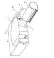
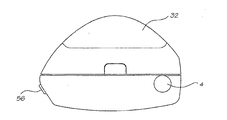
本発明の第1および第2の態様の好ましい実施例は、補充可能な印刷ロール紙上に、要求に応じてステッカを印刷できるステッカ印刷カメラから構成される。添付の図に示す「ステッカカム」1は、外部正面蓋型枠2、内蔵副構造および背面型枠3、ステッカおよびインクカートリッジ型枠4、および外部背面蓋5によって画成される多部構成のハウジングを有する。
Preferred embodiments of the various aspects of the present invention will now be described with reference to FIGS. 1 through 91 of the accompanying drawings.
Preferred embodiments of the first and second aspects of the present invention comprise a sticker printing camera capable of printing stickers on demand on refillable printing roll paper. A “sticker cam” 1 shown in the accompanying drawings is a multi-part housing defined by an external front
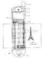
一般的に、図示した好ましい形態におけるハウジングは、正面形状が涙滴状であり、一般的に、円形部6を、印刷ロール紙形状にステッカを収納するよう構成し、残る部に、インク供給器7、印刷ヘッド配列8、およびステッカ供給機構9を格納する。
In general, the housing in the preferred form shown in the figure has a teardrop-like front shape, and generally the
またビューファインダ10を、円形ハウジング部6の中心、あるいはその付近に配置し、正面蓋2からケーシングを介して任意に取り付ける背面の接眼部11までずっと延在している。カメラレンズ12は、ケーシング正面でビューファインダ10の直下に設けるが、このレンズは、図12に示すCCD13等の適切な画像検出および処理手段と動作時に連動する。更に、「撮影」ボタン14を、「印刷」ボタン15と共にケーシング上部に設け、画像の撮影および印刷をそれぞれ行えるようにする。
Further, the
また図示する好ましい「ステッカカム」は、「画像効果用回転盤」16を含むが、この回転盤は、通常、モノクロ、セピア色、ソフトブレンド等の一連の画像効果を実施するように回転可能である。また、ハート、花、思いがけない画像効果等の図形的なクリップアートを追加するのにも用いることができる。回転盤上に、一連のアイコン図形を設け、そこに画像効果を表示するものを印刷してもよい。表示マーカ17に置かれる画像効果が、次にカメラによって適用される画像効果である。画像効果用回転盤は、一連の導電セグメントを回転子の裏に配置することで実行できるが、この導電セグメントは、表示される効果の種類を表す2値パターンを形成する。このセグメントによって、ステッカカムによって監視可能な回路が完全になり、画像効果が提供できる。
The preferred “sticker cam” shown also includes an “image effect turntable” 16, which is usually rotatable to perform a series of image effects such as monochrome, sepia, soft blend, etc. . It can also be used to add graphic clip art such as hearts, flowers, and unexpected image effects. A series of icon figures may be provided on the turntable, and an image effect display may be printed there. The image effect placed on the
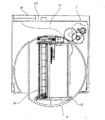
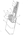
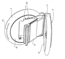
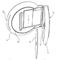
好ましい形態において、ステッカは、ステッカロール18の形態で提供されるが、好ましくは、このステッカを、外装ケーシングに取り外し可能なように固定されるカートリッジ組立品19に格納する。カートリッジは、外装ハウジングと同様の形状および構造であり、上部型枠20から構成されるが、この型枠は、一般的に三角形に区分されるインク収納部22を有する部材21を含む一般的に環状のステッカロールを画成する。好ましくは、インク収納部は、カラーおよびモノクロ印刷を提供するように、複数の個別の小室23に分ける。また2つのスロットを、カートリッジ上部型枠の側壁に設ける。1つ目はステッカ供給口スロット24であり、2つ目はピックアップローラスロット25であるが、このスロット25は、下記に更に詳細に述べるステッカ供給機構27の一部を構成する。またカートリッジ19は、ステッカロール孔およびインク小室両方を封止する母体型枠28を含む。好ましくは、インク注出孔29を、母体型枠に設けるが、この型枠は、プリンタ機構30と流体的に連通するように、設置時に孔開けされた封止薄膜で覆われる。望ましくは、カートリッジは、ステッカおよびインク供給器が同時に補充されるように、封止されたユニットである。都合のよいことに、カートリッジを、図面に示す押圧スナップマウント31によって、外装ハウジングとワンタッチで装着させてもよい。
In a preferred form, the sticker is provided in the form of a
ステッカ供給機構27およびプリンタ機構30を最もよく示す図は、図2、5、7、9、および12である。ステッカ供給機構27は、ピックアップローラ32を含むが、このローラによって、一旦カートリッジが外装ハウジングに挿入されると、ステッカが前方に巻かれる。隣接するピックアップローラは、何対かの駆動ローラ、すなわち、はさみローラ33であるが、このローラは、モータ35によって、対応する歯車チェーン34を介して動作する。またのこぎり状のカッタ36を、供給副組立品の一部として設け、ハウジング正面型枠2の一部として形成される隣接する印刷済ステッカ出口37となるように配設する。あるいは、ギロチンタイプの機構を設ける場合もある。
The best views of the
プリンタ機構30を最もよく示す図は、図6および7であり、インク分配ユニット41を有するページ幅印刷ヘッド先端部40から構成される。インク分配ユニットの一部を形成するものは、インク供給接続連結管42であり、ステッカロールおよびインクカートリッジ19上のインク注出孔29と係合する複数のインク注入凸部43を有する。印刷装置およびステッカ供給機構は、単体ユニットであり、取り外して交換および修理できることが好ましい。
The best view of the
次に、図12(および図5)において、ステッカカム装置を制御および動作するための電気的な回路の一部の概略的な配設を示している。図からわかるように、単純な可撓性のあるPCBハーネスを用いて、撮影ボタン14および印刷ボタン15を、CCD13および印刷ヘッド組立品30に相互接続できる。また回路の一部として設けられるものは、電源供給用の端子45であり、好ましくは、この電源供給は、3Vのバッテリ46の形態を取る。更に好ましくは、着脱式印刷ヘッド、および/あるいはステッカおよびインク供給カートリッジは、出願人の先行PCT出願番号PCT/AU98/00544、表題「内蔵印刷装置付きカメラ」の中で述べているような認証機構を含む。認証チップ端子47を、図12に示す。
Next, FIG. 12 (and FIG. 5) shows a schematic arrangement of a part of an electric circuit for controlling and operating the sticker cam device. As can be seen, the
使用に際しては、「ステッカカム」を対象被写体に向け、次に撮影ボタン14を操作して画像を取り込む。次に画像効果回転盤16を回して、画像効果を選択できる。次に印刷ボタン15を操作すると、ステッカ供給機構27によって、次のステッカあるいはステッカ媒体部を、効果処理された画像をその上に印刷するための印刷ヘッド組立品30に送る。
In use, the “sticker cam” is pointed at the target subject, and then the
本発明全体の概念の範囲内において、多くの変形例が可能である。例えば、印刷ヘッドユニットは、オーストラリア仮特許出願、本発明と合わせて同時出願の、表題「画像生成方法および装置(ART79)」の中で概説されているものに不都合なく適合できるが、その内容は本明細書中に相互参照のため引用している。あるいは、好ましい実施例を、PCT特許出願PCT/AU98/00549(WO99/04551)、これも本出願と合わせて出願の、表題「補充可能な使いきりカメラ装置」の中で開示されている装置の改造品として実現できる。都合がよいことに、画像検出器は、ステッカの寸法が小さいために、上記で参照したPCT出願の中で述べられているものに対して、寸法を小さくできる。 Many variations are possible within the scope of the overall concept of the invention. For example, the print head unit can be adapted inconveniently to the Australian provisional patent application, co-filed with the present invention, outlined in the title “Image Generation Method and Apparatus (ART 79)”, the contents of which are Reference is made herein for cross-reference. Alternatively, a preferred embodiment of the apparatus disclosed in PCT patent application PCT / AU98 / 00549 (WO 99/04551), which is also filed with the present application, under the title “Replenishable single-use camera apparatus”. It can be realized as a modified product. Conveniently, the image detector can be reduced in size relative to that described in the above referenced PCT application due to the small size of the sticker.
同様に、ステッカカムの電子回路は、CMOS画像検出器19付近に備えられるが、この検出器は、画像を処理し、それを印刷ヘッド12に給送して印刷するための処理回路も含む。内蔵制御電子回路の動作については、前述のPCT明細書WO99/04551の中で充分に詳述されている。
Similarly, the electronic circuit of the sticker cam is provided near the
本発明の第2の態様によるカートリッジの好ましい適用例は、補充可能なプリントロール上で、要求に応じてステッカを印刷できるステッカ印刷カメラに対してのものである。
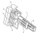
本発明による第3の態様の好ましい形態において、小型プリンタを設けるが、この小型プリンタを、名刺大の用紙上に印刷するよう構成し、PCMCIAタイプIIIカード(PCMCIA(パーソナルコンピュータメモリカード国際協会)によって、標準寸法85.6mm×54mm、厚さ10.5mmのタイプIIIカードを有するいわゆるPCカード用にパラメータを設定している)の大きさに納まるように大きさを決める。しかしながら、下記で説明するPCMCIAインターフェイスプラグによって、PCMCIAスロットを有する直結インターフェイスを組み込む一方で、本発明に基づき製造したプリンタの寸法を大きくし、例えば6インチ(15.2センチメートル)×4インチ(10.2センチメートル)の写真寸法の用紙に印刷することもできることは理解されよう。
A preferred application of the cartridge according to the second aspect of the invention is for a sticker printing camera capable of printing stickers on demand on a refillable print roll.
In a preferred form of the third aspect according to the present invention, a small printer is provided, which is configured to print on business card-sized paper, by a PCMCIA type III card (PCMCIA (Personal Computer Memory Card International Association)). The size is determined so as to fit within the size of a so-called PC card having a standard size of 85.6 mm × 54 mm and a type III card having a thickness of 10.5 mm. However, while the PCMCIA interface plug described below incorporates a direct interface with a PCMCIA slot, the size of the printer manufactured in accordance with the present invention is increased, for example 6 inches (15.2 cm) × 4 inches (10 It will be understood that it can also be printed on sheets of photo dimensions (.2 centimeters).
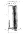
本発明の好ましい形態において、プリンタは、その端面から突き出ているPCMCIAインターフェイスプラグ2を有する支持ケース1、およびその反対の端面において蓋3の下にあるケースをほぼ横切って延びるページ幅のインクジェットプリンタから構成される。
In a preferred form of the invention, the printer is from a
プリンタは、図15および16に更に詳細に示す用紙カートリッジ5を収容するよう構成されたドッキングベイ4を組み込んでいる。
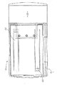
一般的に、用紙カートリッジ5は、用紙積層8を上部から抑えるよう配設される一対の一体型ばね板7を組み込んでいる金属蓋6を有し、用紙をより低い位置へ、下方向(図16に示す方向)へ力を加え、次に積層の最下部の用紙を、正面型枠9下に供給してもよい。
The printer incorporates a
In general, the
カートリッジは、下層基部材10および裏型枠11によって完成する。
蓋3下に位置するページ幅のプリンタ12は、13および14で示すような一連のインク流路貯留容器を含むが、黒インク用の大容量の付加的な貯留容器に加えて、各インク色に1つの貯留容器を備える。貯留容器は、印刷ヘッド付近に形成される。この印刷ヘッドはチップ製造技術によって形成され、CMOSおよびMEMS技術を取り入れた印刷ヘッド30にインク供給する、15、16、17、および18で示すような大きさに徐々に減少していく供給流路を有するが、このCMOSおよびMEMS技術は、オーストラリア仮特許出願番号第PP6534号、出願日1998年10月16日、本出願人に譲渡され、本明細書中に相互参照のため引用する、表題「マイクロ機械装置および方法(IJ46a)」の中で開示されているものと同様である。
The cartridge is completed by the lower
The
更に、プリンタユニット12は、ローラ19、20を含むが、このローラは、まずカートリッジ5の積層8から最下部の用紙を引き出し、印刷ヘッド30を横切って用紙を前方に送り、要求に応じて印刷し、プリンタから供給口スロット21を介して用紙を排紙するよう配設される。ローラは、電気モータ22から変速機23を経由して駆動される。
In addition, the
プリンタは、PCMCIAインターフェイス2とプリンタユニット12の間で相互接続されるプリンタ制御チップによって制御され、このチップは、印刷ヘッド24内あるいはドッキングベイ4の底部下のフレキシブルプリント回路基板内に実装してもよい。
The printer is controlled by a printer control chip interconnected between the
また印刷ヘッドを駆動する電子回路は、ASIC(特定用途向け集積回路)装置を含むことができるが、このASICによって、交換が必要になる前に使い切りのプリンタユニット12が提供される。「認証チップ」の形態において、この回路は、これも本出願人に譲渡される国際特許出願第PCT/AU98/00544号の中で開示されているものと同様のものであることが好ましい。
The electronic circuit that drives the print head can also include an ASIC (Application Specific Integrated Circuit) device, which provides a single
印刷装置12に対する独立した要素として、着脱式用紙カートリッジ5を備えることによって、用紙供給の補充準備ができるようになる。
この種の持ち運び式プリンタは、要求に応じて非常に小型で持ち運び可能な装置から名刺を印刷することを含む、多くの異なる適用例を有するが、この装置は、相互接続ケーブルあるいは他の装置を用いることなく、ラップトップあるいはノートブック型コンピュータのPCカードスロットと直接繋ぐことができる。このプリンタの拡大型のものは、これもPCMCIAインターフェイスプラグを備えるが、同様の方法でより大きい材料を印刷する、例えば6インチ(15.2センチメートル)×4インチ(10.2センチメートル)サイズの写真、あるいは他の同様な材料の印刷に用いることができる。
By providing the
This type of portable printer has many different applications, including printing business cards from a very small and portable device on demand, but this device uses an interconnect cable or other device. Without use, it can be directly connected to a PC card slot of a laptop or notebook computer. The enlarged version of this printer, which also has a PCMCIA interface plug, prints larger materials in a similar manner, eg 6 inch (15.2 cm) x 4 inch (10.2 cm) size Can be used for printing photos or other similar materials.
まず、第4の態様のオンデマンド方式印刷カメラ装置について、カメラ装置と連結できる着脱式プリンタユニットを参照して述べる。
本発明の好ましい形態において、この小型プリンタを、名刺大の用紙上に印刷するよう構成し、PCMCIAタイプIIIカード(PCMCIA(パーソナルコンピュータメモリカード国際協会)によって、標準寸法85.6mm×54mm、厚さ10.5mmのタイプIIIカードを有するいわゆるPCカードのためのパラメータが設定されている)の大きさに納まるよう寸法を決定する。しかしながら、下記で説明するPCMCIAインターフェイスプラグによって、PCMCIAスロットを有する直結インターフェイスを組み込む一方で、本発明に基づき製造したプリンタの寸法を大きくし、例えば6インチ(15.2センチメートル)×4インチ(10.2センチメートル)の写真寸法の用紙に印刷することもできることは理解されよう。
First, an on-demand printing camera device according to a fourth aspect will be described with reference to a detachable printer unit that can be connected to the camera device.
In a preferred form of the invention, the small printer is configured to print on business card-sized paper and is PCMCIA type III card (PCMCIA (Personal Computer Memory Card International Association)) standard dimensions 85.6 mm x 54 mm, thickness. The dimensions are determined so as to fit within the size of a so-called PC card having a type III card of 10.5 mm. However, while the PCMCIA interface plug described below incorporates a direct interface with a PCMCIA slot, the size of the printer manufactured in accordance with the present invention is increased, for example 6 inches (15.2 cm) × 4 inches (10 It will be understood that it can also be printed on sheets of photo dimensions (.2 centimeters).
本発明の好ましい形態において、プリンタは、その端面から突き出ているPCMCIAインターフェイスプラグ2を有する支持ケース1、およびその反対の端面において蓋3の下にあるケースをほぼ横切って延びるページ幅のインクジェットプリンタから構成される。
In a preferred form of the invention, the printer is from a
プリンタには、図2および3に更に詳細に示す用紙カートリッジ5を収容するよう構成されたドッキングベイ4を組み込んでいる。
一般的に、用紙カートリッジ5は、用紙積層8を上部から抑えるよう配設される一対の一体型ばね板7を組み込んでいる金属蓋6を有し、用紙をより低い位置へ、下方向(図20に示す方向)へ力を加え、次に積層の最下部の用紙を、正面型枠9下に供給してもよい。
The printer incorporates a
In general, the
カートリッジは、下層基部材10および裏型枠11によって完成する。
蓋3の下に位置するページ幅のプリンタ12は、13および14で示すような一連のインク流路貯留容器を含むが、黒インク用の大容量の追加的な貯留容器に加えて、各インク色に1つの貯留容器を備える。貯留容器は、印刷ヘッド付近に形成され、この印刷ヘッドは、チップ製造技術によって形成され、CMOSおよびMEMS技術を組み込んでいる印刷ヘッド30にインク供給する、15、16、17、および18で示すような大きさに徐々に減少していく供給流路を有するが、このCMOSおよびMEMS技術は、オーストラリア仮特許出願番号第PP6534号、出願日1998年10月16日、本出願人に譲渡され、本明細書中に相互参照のため引用する、表題「マイクロ機械装置および方法(IJ46a)」の中で開示されているものと同様である。
The cartridge is completed by the lower
The
更に、プリンタユニット12は、ローラ19、20を含むが、このローラは、まずカートリッジ5の積層8から最下部の用紙を引き出し、印刷ヘッド30を横切って用紙を前方に送り、要求に応じて印刷し、プリンタから供給口スロット21を介して用紙を排紙するよう配設される。ローラは、電気モータ22から変速機23を経由して駆動される。
In addition, the
プリンタは、PCMCIAインターフェイス2とプリンタユニット12の間で相互接続されるプリンタ制御チップによって制御され、このチップを、印刷ヘッド24内あるいはドッキングベイ4の底部下のフレキシブルプリント回路基板内に組み込んでもよい。
The printer is controlled by a printer control chip interconnected between the
また印刷ヘッドを駆動する電子回路は、ASIC(特定用途向け集積回路)装置を含むことができるが、このASICによって、交換が必要になる前に使い切りのプリンタユニット12が提供される。好ましくは、「認証チップ」の形態において、この回路は、これも本出願人に譲渡される国際特許出願第PCT/AU98/00544号の中で開示されているものと同様のものであることが好ましい。
The electronic circuit that drives the print head can also include an ASIC (Application Specific Integrated Circuit) device, which provides a single
印刷装置12に対する独立した要素として、着脱式用紙カートリッジ5を備えることによって、用紙供給の補充準備ができるようになる。
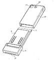
プリンタユニットをカメラ装置内に係止し、図22および23に示すような完全なカメラユニットを設ける。このカメラユニットは、プリンタユニット蓋3を備えるプリンタユニットを収容するようにしたカメラ本体25から構成され、その供給口スロット21は、ハウジングから突き出ている。
By providing the
The printer unit is locked in the camera device to provide a complete camera unit as shown in FIGS. This camera unit is composed of a
更にカメラは、レンズ26、および正面窓27と接眼部28を有するビューファインダを組み込んでいる。簡便ドア29を設けて、カメラに電力を供給するのに用いられる単体のあるいは複数のバッテリに手が届くようにしてもよい。
The camera further incorporates a
このカメラは、「シャッター」ボタン30および着脱式プリンタユニットの動作を制御するよう配設される印刷ボタン31を含む。
上記で述べたように、用紙カートリッジ5は、図25において明らかにわかるように、用紙を補充するために、プリンタユニットから取り外すことができる。
The camera includes a “shutter”
As mentioned above, the
カメラ本体25の内部に、着脱式プリンタユニットの端面でPCMCIAプラグ2と係止可能なPCMCIAスロット32(図10)を設ける。プリンタユニットをカメラ本体に挿入する場合、プラグ2を、着脱式プリンタユニットとカメラ本体の間で適切に電気的な相互接続を行うスロット32に係止する。
A PCMCIA slot 32 (FIG. 10) that can be locked to the
更にカメラユニットは、一般的にレンズ26の背後に直接位置するCCD33(図26)の形態で画像検出器を組み込んでいる。CCD33を、柔軟性のあるPCB34によって、画像処理手段を組み込んでいる主PCB35に接続するが、この画像処理手段によって、CCDからの信号を処理し、次にPCカードスロット32にその信号を送信する。
In addition, the camera unit incorporates an image detector in the form of a CCD 33 (FIG. 26) that is generally located directly behind the
カメラ装置は、蝶番で留められるドア29を通して挿入されるバッテリ35によって電力供給される。
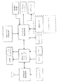
図28において、装置の動作部を概略的に図示しているが、この装置は、通信母線によって相互接続され、カメラレンズによって高解像度画像を取り込むCMOS画像検出器(CCD)37を含む。処理ユニット38によって、画像を処理し、その画像をプリンタ制御チップ39に供給するが、このチップは、着脱式プリンタユニットに位置し、次に印刷ヘッド40を制御して、画像41を生成する。記憶装置42を、カメラユニット内で中間記憶装置として利用するが、このカメラユニットも、画像がプリンタユニットに送信される前に、画像を編集するための制御装置を含んでもよい。
The camera device is powered by a
In FIG. 28, the operating part of the device is schematically illustrated, which includes a CMOS image detector (CCD) 37 interconnected by a communication bus and capturing a high resolution image with a camera lens. The
このようにして、オンデマンド方式印刷カメラ装置を設けるが、これによって、着脱式であり、また多目的のプリンタユニットを、必要に応じて写真印刷に用いることが可能になり、また、プリンタユニットを、PCMCIAインターフェイスによって他の装置と繋ぐことによって、他の目的に利用用することが可能になる。 In this way, an on-demand printing camera device is provided, which makes it possible to use a detachable and multi-purpose printer unit for photo printing as required. By connecting to other devices through the PCMCIA interface, it can be used for other purposes.
本発明による第5の態様の好ましい実施例において、プリンタユニットを提供するが、このプリンタユニットは、従来のPCのディスクドライブベイに納まるようにした全体の大きさおよび形状を有する。プリンタユニットは、ページ幅のインクジェット印刷ヘッド、印刷制御装置チップ、および消耗品インクおよび用紙供給カートリッジを組み込んでいる装置を用いるが、このカートリッジは、国際特許出願PCT/AU98/00544、表題「内蔵印刷装置付きカメラ」の中で詳細に述べられている種類のものであり、その内容を本明細書中に相互参照のために引用している。 In a preferred embodiment of the fifth aspect of the present invention, a printer unit is provided, the printer unit having an overall size and shape adapted to fit in a conventional PC disk drive bay. The printer unit uses a page width inkjet printhead, a print controller chip, and a device that incorporates consumable ink and paper supply cartridges, which are international patent application PCT / AU98 / 00544, entitled “Built-in Print”. It is of the type described in detail in “Camera with Device”, the contents of which are incorporated herein for cross-reference.
前述のPCT出願に、一体型プリンタを有するカメラ装置が開示されているが、このプリンタは、インク、およびその上に画像を要求に応じて印刷する「用紙」あるいは他の印刷媒体(本明細書を通して用紙と呼ぶ)を含む印刷ロールを利用する。本発明の好ましい実施例においては、国際出願PCT/AU98/00544のカメラ装置の画像検出部を省いており、印刷ロールおよび印刷ヘッドは、PCのディスクドライブベイ内に納まるよう形成されたプリンタユニット内に組み込まれるように構成される。 In the aforementioned PCT application, a camera device having an integrated printer is disclosed, but this printer is a “paper” or other print medium (herein) on which ink and images are printed on demand. A printing roll containing paper). In a preferred embodiment of the present invention, the image detection unit of the camera device of the international application PCT / AU98 / 00544 is omitted, and the printing roll and the printing head are in a printer unit formed to fit in the disk drive bay of the PC. Configured to be incorporated into
好ましくは、プリンタユニット1は、PCのディスクドライブユニット内に挿入するために設計され、一般的に、係止つまみ3、排出ボタン4、および電源LED5を有する副フレーム2に回転可能に取り付けられる。プリンタユニットは、図1において明らかにわかるように、用紙供給口スロット6を有する。
Preferably, the
図30に、前述の国際特許出願の中で説明されている種類の用紙およびインクカートリッジを挿入するために、プリンタユニットを90°回転させた状態の図29のユニットを示す。一般的に、プリンタユニットは、歯車列8を介して動作する電気モータ7(図32)で回転され、プリンタユニットが、図1に示す動作位置と図30に示す装填位置との間で回転する。装填位置において、装填ドア9を、図31に示すような蝶番10で外方向に開いて、インクおよび用紙カートリッジ12を収容するようにした開口部11が現れる。
FIG. 30 shows the unit of FIG. 29 with the printer unit rotated 90 ° to insert paper and ink cartridges of the type described in the aforementioned international patent application. In general, the printer unit is rotated by an electric motor 7 (FIG. 32) that operates via a
インクおよび用紙カートリッジ12を、細長い形状にし、図31から明らかになるように、長手方向にプリンタユニット内に挿入できるよう構成する。
図32に、柔軟性のあるPCB13および14を含むプリンタユニットの内部配列をいくつか示すが、このPCB13および14によって、その後のPCB15から、PCディスクドライブベイの標準規格インターフェイスと連結可能な標準規格コネクタ16、および印刷ヘッドに、各々電子回路を接続する。
The ink and
FIG. 32 shows several internal arrangements of the printer unit including
印刷ヘッドは、国際出願PCT/AU98/00544の中で詳述されているようにインクおよび用紙カートリッジからインクを供給される、図32の16に示すようなページ幅のインクジェット印刷ヘッドであることが好ましい。また図32においては、印刷ロール排紙装置17が示されている。
The print head may be a page width ink jet print head as shown at 16 in FIG. 32, supplied with ink from ink and paper cartridges as detailed in international application PCT / AU98 / 00544. preferable. Further, in FIG. 32, the printing roll
ページ幅の印刷ヘッドの断面図は、印刷小室、印刷ヘッドのキャッピング機構19、および用紙カッタ20を明確に示す図7に見ることができる。また図35において明らかなように、印刷ロールドアソレノイド21によって、印刷ロールドア22を開閉動作できる。
A cross-sectional view of a page-width print head can be seen in FIG. 7, which clearly shows the print chamber, the print
図36の縦断面図に、印刷ロールベイコネクタ16、主プリンタ回路基板23、回転式ドラムドライブモータ7、歯車8、およびドラム基部9を明確に示す。また図36に、印刷ロール12と印刷小室18の間に延びるインク流路24も示す。用紙カッタ20は、モータ駆動機25によって駆動される。
The printing
また、図36において見られるように、印刷ロールモータ26および歯車列27を、国際出願PCT/AU98/00544の中で既に述べられている同様の方法で、印刷ロールを駆動するように配設する。
Also, as seen in FIG. 36, the
次に図38において、本発明の好ましい実施例の概略的な動作を示す。好ましくは、コンピュータ装置によって、印刷データが、印刷制御装置チップ28に送られるが、このチップは、前述のPCT出願の中で検討したようなACPチップの変更形態でもよい。このACPチップは、印刷ヘッドおよび印刷ロールの動作制御の役割を担い、要求に応じて画像を印刷出力し、前述の出願の中で検討したように、基板上に認証装置を有することが可能な印刷ロール29の認証を行う。
Next, in FIG. 38, the schematic operation of the preferred embodiment of the present invention is shown. Preferably, the computer device sends the print data to the
このようにして、プリンタユニットを設け、PCのディスクドライブベイ内に全体が含まれるよう構成された、小型で且つ簡易に配置されるプリンタユニットから、写真サイズ(一般的に6インチ(15.2センチメートル)×4インチ(10.2センチメートル))の画像を印刷できる。 In this way, from a small and easily arranged printer unit that is provided with a printer unit and is entirely contained within a PC disk drive bay, a photo size (generally 6 inches (15.2). Centimeters) × 4 inches (10.2 centimeters).
第6の本発明の態様による両実施例において、内蔵着脱式プリンタを有する携帯電話を提供するが、このプリンタは、別々に着脱式印刷ヘッドとインク供給ユニット組立品を含み、更に好ましくは、別々に着脱式の用紙供給器あるいは他の印刷媒体を含む。少なくとも第1の好ましい実施例の携帯電話プリンタは、それによって動作中に高いレベルの利便性を与える標準的な大きさのものである。2つの実施例の主な相違点は、印刷媒体の形態、およびインク供給器の位置に関する。 In both embodiments according to the sixth aspect of the present invention, there is provided a mobile phone having a built-in removable printer, the printer separately including a removable print head and an ink supply unit assembly, more preferably separately. Includes a detachable paper feeder or other print media. The mobile phone printer of at least the first preferred embodiment is of a standard size thereby providing a high level of convenience during operation. The main differences between the two embodiments relate to the form of the print media and the location of the ink supply.
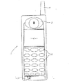
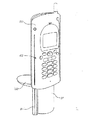
初めに、図39において、好ましい実施例の印刷機能付き電話1を示しているが、この印刷機能付き電話は、耳当部2、マイク部3、アンテナ部4、一連の押ボタン5、および好ましくは、情報表示用のカラーLCD画面6を含む従来の携帯電話のように見えるものである。
First, in FIG. 39, a
図40において、第1実施例の電話1の裏面部を、印刷媒体貯蔵容器9を明瞭にするように取り外したバッテリ蓋8と共に示すが、その容器から、名刺大のカードあるいはシート10を、プリンタユニット12によってその上に画像を印刷するよう用いる。カード上への印刷出力は、電子メールあるいは他の機能のように携帯電話によりダウンロードされる処理済み信号情報である。
In FIG. 40, the back side of the
携帯電話1が、画像を印刷出力し、あるいは画像を取り込み、携帯ネットワークに送り出すためのカメラ装置として効果的に機能することができるように、携帯電話は、例えば、要求に応じて画像を検出および記憶するように構成したCMOS検出器から構成されるカメラ装置13を任意で備え付けることができる。
The mobile phone detects, for example, an image on demand, so that the
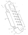
図41は、第1携帯電話装置1の部断面分解斜視図であり、印刷ヘッド組立品16および供給手段17を含むプリンタ組立品12を更に詳細に示している。用紙ハウジング9は、ばね板14によって弾力的に縮められる一連のカード10を含む。他の図に示すように、印刷媒体供給手段17を、ピンチローラ18の形態で設けるが、このローラはモータ19によって歯車列20を介して駆動され、また個々のカード10を、印刷ヘッド16へ、また印刷ヘッド16を経て駆動するために用いられる。印刷ヘッドは、任意に交換可能な印刷ヘッドの一部およびインク分配ユニット22を含むインク分配ユニット組立品21を形成してもよく、オーストラリア仮特許出願番号第PP6534号、出願日1998年10月16日、その内容は本明細書中に相互参照のため引用しているが、表題「マイクロ機械装置および方法(IJ46A)」の中で開示されているものとほぼ同様のものである。
FIG. 41 is a partial sectional exploded perspective view of the first
この第1の実施例のインク分配ユニット22は、フルカラー印刷のために設けられる一連のインク供給貯留容器23乃至26を含む。この貯留容器23は、貯留容器22乃至26よりも実質的に大きく、黒インクを収納するのに利用できる。このインク供給器は、黒の15%被写域で約2000枚を、あるいはCMYK50%被写域の約200枚の写真を印刷するのに充分である。プリンタ組立品12の更に詳細な図を、前述の仮特許出願の明細書の中で開示されている詳細な技術の記載と共に、図42Aに示す。
The
携帯電話装置は、一連の1つ以上の特定用途向け集積回路(ASICS)の制御下で、電子的に動作できるが、この回路は、カメラおよび画像処理能力に加えて、通常の携帯電話能力を組み込んでいる。第1実施例のための電気的な相互接続を表すブロック図例を図44に示す。本願によって申請されたPCT特許出願PCT/AU98/00544の中で概説されているような装置を適切に適用することをASICの設計に利用できる。他の選択可能な装置設計は、特にこの技術分野に精通した当業者の知識に基づき組み込み可能である。 A mobile phone device can operate electronically under the control of a series of one or more application specific integrated circuits (ASICS), which in addition to the camera and image processing capabilities, Incorporated. An example block diagram representing the electrical interconnection for the first embodiment is shown in FIG. Appropriate application of the device as outlined in PCT patent application PCT / AU98 / 00544 filed by the present application can be used for ASIC design. Other selectable device designs can be incorporated, particularly based on the knowledge of those skilled in the art.
電話装置における他の各部の名称/構成要素を、その機能は容易に明らかとなろうが、添付の図中において以下の参照番号で識別する。 The names / components of other parts of the telephone device are identified by the following reference numbers in the accompanying drawings, although their functions will be readily apparent.

2つの実施例の間における主な相違点は、カード供給装置およびインク供給器と一体型の印刷ヘッドを有する代わりに、この第2の実施例は、交換可能な用紙およびインク印刷ロールカートリッジを用いることである。このカートリッジは、出願人の先行出願、その内容全てを本明細書中に相互参照のために引用するが、USSN09/113,073「一体型印刷ロール付きデジタルカメラ装置」、USSN09/113,053「印刷媒体ロールおよびインク交換可能なカートリッジ」、USSN09/112,744「巻き取り媒体におけるねじれを低減するための異方性剛性」、USSN09/112,823「インクおよび用紙カートリッジを用いる小型カラープリンタ」、およびUSSN09/112,783「軸流インク小室付きインクおよび媒体カートリッジ」の中で説明されているものとほぼ同様である。 The main difference between the two embodiments is that instead of having a print head integral with the card feeder and ink feeder, this second embodiment uses replaceable paper and ink print roll cartridges. That is. This cartridge is the applicant's prior application, the entire contents of which are cited herein for cross-reference, but USSN 09 / 113,073 “Digital Camera Device with Integrated Printing Roll”, USSN 09 / 113,053 “ Print media roll and ink replaceable cartridges ", USSN 09 / 112,744" anisotropic stiffness to reduce twist in winding media ", USSN 09 / 112,823" small color printer using ink and paper cartridges ", And USSN 09 / 112,783 “Ink and Media Cartridge with Axial Flow Chamber”.
他の相違点は、走査機能を任意で含むことである。第2実施例を参照して述べる。実際、この機能は、印刷ロールの形態で印刷媒体に用いるのにより適切であるが、これは第1実施例にも含まれる。更に走査機器を収納するのに必要な追加的な空間によって、設計上第1実施例ほど小型でない第2実施例に対しては問題が小さくなる。更に詳細なこれらの相違点の特徴は以下に述べる。 Another difference is that it optionally includes a scanning function. The second embodiment will be described. In fact, this function is more suitable for use with print media in the form of a print roll, but this is also included in the first embodiment. Furthermore, the additional space required to accommodate the scanning device reduces the problem for the second embodiment, which is not as compact in design as the first embodiment. More detailed features of these differences are described below.
第2実施例において、電話ケーシング50を、電話の基部に形成されるカートリッジハッチ52によって、用紙およびインク印刷ロールカートリッジ51を収容するよう形成する。また電話の基部に設けられるものは、DC入力53およびUSBコネクタ54である。
In the second embodiment, the
この特定の実施例において、カメラ装置13は電話の背面に配置され、カメラ撮影ボタン56によって動作可能である。また印刷機能付き電話は、線形CMOS画像検出器の形態を取る走査ヘッド(図示せず)を含むが、この検出器は、電話正面に入口58、および電話背面に供給口59を有する走査画像スロット57によって画成される画像走査経路に隣接するケーシングの右側面内に配置する。
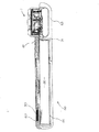
図52において最もよくわかるように、用紙およびインク印刷ロールカートリッジ51は、従来の35mmカメラフィルムに似た形状であり、設置時、電話容器50の正面左側面に形成される、対応するプリンタ供給口スロット62と位置合わせされる用紙供給口61を有する。しかしながら、カートリッジ51は充分に長く、好ましくは、写真印刷の従来の大きさである各々100mm×150mmの36枚に対して充分な画像用印刷媒体およびインクを含む。印刷ヘッドおよびインク供給器ユニット組立品21を、65で識別する母体型枠部の後ろに配置する。
In this particular embodiment, the
As best seen in FIG. 52, the paper and ink
また第2の実施例の印刷機能付き電話1は、一連の1つ以上のASICチップによる制御下で動作するが、このチップは、カメラおよび走査画像処理機能に加えて、通常の携帯電話機能を組み込んでいる。再び、本出願によって申請されたPCT特許出願PCT/AU98/00544の中で概説されているような装置の適切な適用をASICチップの設計に用いる。
In addition, the
使用上、この第2実施例の動作は、追加的な走査機能を除いて、第1の実施例とほとんど同じである。用紙およびインク供給器の交換は、カートリッジハッチ52を開くだけで行うことができ、古いカートリッジを取り外して新しいものを挿入する。カートリッジは、印刷ヘッドと接続されたインク分配組立品上のノズルと繋がる孔の開いたインク供給口を含む。
In use, the operation of this second embodiment is almost the same as the first embodiment, except for the additional scanning function. The paper and ink supply can be replaced simply by opening the
図示する第7の本発明による態様の好ましい実施例において、内蔵プリンタを有する携帯電話を提供するが、このプリンタは、別々の着脱式印刷ヘッドおよびインク供給モジュールを含む。印刷機能付き電話は、PHS、GSM、およびGPRSを含むあらゆる装置用に、標準規格寸法の電話で、あるいはそれに近い寸法で製造することができ、それによって動作中により利便性が高くなる。 In a preferred embodiment of the illustrated embodiment according to the seventh aspect of the present invention, a mobile phone having a built-in printer is provided, which includes a separate removable print head and an ink supply module. Printable phones can be manufactured on or near standard size phones for any device, including PHS, GSM, and GPRS, thereby making it more convenient during operation.
初めに図54において、PHS方式電話の形態を取る好ましい実施例を示すが、この実施例は、耳当部2、マイク部3、アンテナ部4、一連の押ボタン5、および好ましくは、情報表示用のカラーLCD画面6を含むこの種の従来の携帯電話のように多くの点で類似しており、またその特徴を含む。また図57に示すように、バッテリ8も含む。
First, in FIG. 54, a preferred embodiment in the form of a PHS phone is shown, which is an
電話1は、レンズ11、および関連CCDチップあるいはCMOS検出器12から構成されるカメラ装置10を任意に組み込んでいる。CCDあるいはCMOS検出器によって、装置が要求に応じて画像を記憶することが可能となり、そのため電話は画像を印刷出力する、すなわち画像の取り込みおよび携帯電話ネットワークを横断して供給するためのカメラ装置として効果的に機能する。内蔵制御電子回路の関連部の動作は、本出願人の先行PCT出願WO99/04551、その内容を参照のため本明細書中に引用するが、表題「補充可能な使い切りカメラ装置」の中で充分に詳述されている。他の実施例において、カメラ装置はまた、通話中に同時に画像処理を容易に行えるようにすることによって画像の複数通話が可能なように構成する。選択的な可動位置調整のために電話装置に取り付けられるカメラ機能はこの目的に利用してもよい。例えば、カメラに対向する前面と、画像の複数通話側に対向する背面の間で回転可能であってもよい。
The
印刷装置は、全般的に15で示し、印刷ヘッドおよびインク供給モジュール16から構成されるが、このモジュールは、印刷ヘッド17、インク供給/分配ユニット18、および印刷媒体供給装置20を含む。供給装置は、一連の供給ローラ23を駆動する関連する歯車列22を備えるモータ21を含む従来の形態である。
The printing device is indicated generally at 15 and is comprised of a print head and
印刷装置15のパッケージ部は、図58、59および62に最もよく示されている。このように、印刷機能付き電話1は、剛性シャーシ型枠25付近に組み立てられる。このシャーシは、印刷ヘッドモジュール16の外装ケーシング上に設けられるフランジ26を保持することによって、印刷ヘッドおよびインク供給モジュール16を滑動して収容し、保持するよう構成される。
The packaging portion of the
印刷装置15の全体の動作は、図62に最もよく示されている。使用上、印刷媒体30は、好ましくは名刺大の用紙あるいはカード用紙の形態を取るが、外装電話ケーシング32に設けられる入口スロット31を介して供給送入される。これは手差しで、あるいはこの後説明するような供給装置によって行うことができる。次に、カード30を、電動入口供給ローラ23によって摘み上げ、印刷ヘッドモジュール16に給送する。印刷ヘッドおよびインク供給モジュールは、オーストラリア仮特許出願番号第PP6534号、出願日1998年10月16日、その内容もまた本明細書中に相互参照のため引用するが、表題「マイクロ機械装置および方法(IJ46A)」の中で開示されているものとほぼ同様のものである。このような装置において、印刷ヘッドは、印刷媒体経路長全体に延在する細長い印刷ヘッドチップの形態を取り、そのため、印刷ヘッド往復機構を必要とせずに、単路において印刷媒体幅全体に印刷する。
The overall operation of the
この特に好ましい実施例において、印刷ヘッドおよびインクモジュールは、封止したユニットとして形成されるが、このユニットは、所定の量が使用された後、その全体を交換する。インク供給器および印刷ヘッドモジュールの詳細な構造を、図61にさらに明確に示す。インク供給/分配ユニット18は、蓋35を含む複部要素で成型された構造であり、4区分のインク供給器小室37乃至40を画成する広範流路型枠36は、任意の流体制御バッフル41を有する。広範流路型枠36の収束供給口と接続するものは、微小型枠42であるが、この微小型枠は、インクを印刷ヘッド17の背面上の微量インク供給入口に正確に導く同様の収束インク流体ノズル43を画成する。インクフィルタ44を、任意に2つの型枠の間に設ける。またキャッピング装置47は、印刷ヘッドを使用しない時は、ノズル供給口を封止し防護するためのモジュールの一部として設けられる。インク供給器は、平均して、黒の15%被写域で約1000枚を、あるいはCMYK50%被写域の約100枚の写真を印刷するのに充分である。印刷ヘッドおよびインク供給モジュールの詳細な技術の説明は、前述の仮特許出願PP6534および関連出願の中に見出すことができる。
In this particularly preferred embodiment, the print head and ink module are formed as a sealed unit, which unit is replaced in its entirety after a predetermined amount has been used. The detailed structure of the ink supply and printhead module is shown more clearly in FIG. The ink supply /
携帯電話装置を、一連の1つ以上の特定用途向け集積回路(ASICS)の制御下で動作するが、この集積回路は、カメラおよび画像処理機能に加えて、通常の携帯電話機能を組み込んでいる。本出願によって申請されたPCT特許出願PCT/AU98/00544の中で概説されているような装置の適用を、ASICの設計に利用することができる。好ましい実施例のための電気的な相互接続を、ブロック図として図16に示す。またこの技術分野に精通した当業者には公知の他の装置設計を用いてもよい。 A mobile phone device operates under the control of a series of one or more application specific integrated circuits (ASICS), which incorporate normal mobile phone functions in addition to camera and image processing functions. . Application of the device as outlined in PCT patent application PCT / AU98 / 00544 filed by this application can be utilized for the design of ASICs. The electrical interconnection for the preferred embodiment is shown in block diagram form in FIG. Other device designs known to those skilled in the art may also be used.
次に図64乃至68において、既述の実施例のPHS方式電話に用いるために構成された供給装置50が図示されている。供給装置は、下層型枠51から構成されるが、この型枠は、媒体収納および供給領域52、および印刷機能付き電話1を支持し、それを供給装置供給口に位置合わせする受け台53を画成する。
Next, in FIGS. 64 to 68, a
電話1を備える印刷媒体供給装置の相互動作は、図67に最もよく図示されている。そこでわかるように、供給装置50は、名刺サイズの用紙あるいはカード用紙54の形態を取る印刷媒体量が配列される収納場所52を有する。これらのカードは、図68に示すような対向する指バネ56で付勢される金属性板55上で支えられる。このようにして、供給用カードは、媒体排出機構58方向に、常に上向きに付勢される。排紙機構は、排紙滑動子59を含むが、この滑動子は、戻しばね60に反して手動で滑動させ動作可能となり、上部カードを摘み上げ、これを供給装置供給口61の外に、また電話1の媒体入口スロット31内に供給する。開放時に、滑動子は原点に自動的に戻り、次のカードと繋がり、その後の装填を行う。
The interaction of the print media supply device with
印刷機能付き電話1および/あるいは印刷ヘッドおよびインク供給モジュール16は、出願人の先行PCT出願番号PCT/AU98/00544、表題「内蔵印刷装置付きカメラ」の中で概説されているような認証機構を含むことが望ましい。これを用いることで確実にできることは、認証された認証済消耗品(印刷ヘッドおよびインク供給モジュール等)を、印刷機能付き電話に用いることだけでなく、インクあるいは印刷ヘッド自体等の消耗品構成要素の相対的な使用頻度のデータの記憶に用いること、および所定のこれら要素の使用頻度を設定するのに任意に用いることである。
The
上述したように、本発明の電話装置は、どのような種類の携帯電話であってもよく、印刷可能な形態に処理できるように信号を送受信する。更に既述の好ましい形態は、一体型に形成され、取り付け式インク供給器を有する印刷ヘッドおよびインク分配ユニットを有するが、このインク供給器を別々にすることができ、また任意に個別に補充可能である。 As described above, the telephone device of the present invention may be any type of mobile phone, and transmits and receives signals so that it can be processed into a printable form. Furthermore, the preferred form described has a print head and an ink distribution unit which are integrally formed and have a mounted ink supply, but this ink supply can be separate and can be refilled individually. It is.
第8の本発明の態様による図示する好ましい実施例において、ビデオゲーム装置を提供するが、この装置には、好ましくは、名刺大のカード上に、ビデオゲームの双方向性を高める情報を印刷出力可能な一体型プリンタが含まれる。 In the illustrated preferred embodiment in accordance with the eighth aspect of the present invention, a video game device is provided, which preferably prints out information that enhances the interactivity of the video game on a business card-sized card. Possible integrated printers are included.
図においては、プリンタモジュール2およびデジタルビデオディスク(DVD)再生装置モジュール3から構成されるビデオゲーム操作1が示されている。コンソールに接続するものは、図70に示すような任意に取り外せる制御装置モジュール4である。着脱式制御装置モジュールは、「ブルートゥース(商標)」のような無線装置あるいはケーブル等を含む何らかの適切な手段でコンソールと通信でき、磁気結合5あるいは機械的連結を含む何らかの適切な手段で、コンソールと取り外しできるように固定する。
In the figure, a
プリンタモジュール2およびDVD再生装置モジュール3を、図3に示すような浮動軸8のまわりを蝶番式に動く、ハウジング拡張部6および7を接続することによって相互接続する。好ましくは、下位接続拡張部7は、様々な入力/出力コネクタ、およびジョイスティックや他の対話型装置を任意に接続するためのポート9を含む。また、ビデオ出力ポートも設けて、この技術分野に共通の標準規格のビデオタイプ装置との接続を提供する。後続のポートを設けて、外部電源、あるいはコンソールに相互接続される音響装置等の他の装置を提供する。
The
DVD再生機モジュール3は、この産業分野では一般的になりつつある標準規格のDVDゲームディスク10を採用できる。DVD再生機は、ハイエンド演算処理装置(図示せず)と相互接続される。この演算処理装置は、標準的なハイエンドビデオゲーム用演算処理装置と同様の生産ラインで、あるいは、その内容を本明細書中に相互参照のため具体的に引用するが、PCT特許出願番号PCT/AU98/00544の中で検討されている生産ラインで製造できる。次に、演算処理装置は、標準的なビデオゲーム機能のための記憶装置を利用し、印刷制御装置チップとやり取りするが、このチップもまた、プリンタモジュール2内のPCB11上のハイエンド演算処理装置と共に格納されるのが好ましい。制御装置チップ(これも図示せず)は、オーストラリア仮特許出願明細書、出願日1998年11月9日、その内容も相互参照のために引用するが、表題「画像生成方法および装置(ART77)」の中で詳説されている生産ラインで組み立てることができる。好ましくは、コンソールを駆動するためのバッテリは、矢印12で示すDVD再生機モジュールの基礎部に設置する。
The
プリンタモジュール2は、同時にDVD再生装置モジュール3を閉じられるように構成することが好ましい。このことは、図示のように、DVDモジュールに対してプリンタユニットを蝶番式に動かすことによって達成される。プリンタモジュール2は、母体型枠14から構成されるが、この型枠を、DVD再生装置モジュール3の上部面に形成されるDVDディスク受け区室15を完全に囲むように設計する。更に、基礎成型14は、その下部面において、インクおよび用紙カートリッジ18を受け位置させるように構成された一体型シャーシ構造16を画成するよう設計する。
The
シャーシ構造16の上部面は、印刷ヘッドおよびインク分配組立品19、印刷媒体供給機構20、およびインク接続蛇管21を支持するように設計され、インク入口ノズル23を有するシャーシ上の後半連結インク供給口ノズル22を、印刷ヘッドおよびインク分配組立品19上に設ける。また、プリンタおよびDVD制御PCB10も、チャーシ16上に支持され、そこから延びてDVDと上部蓋型枠29上に設けるプリンタ制御ボタン27および28を相互接続する柔軟性のある接続部26を有する。
The upper surface of the
印刷ヘッド、インク分配組立品、および印刷媒体供給手段の詳細を、図77に示す。印刷ヘッドは、好ましくはページ幅のインクジェット印刷ヘッドチップの形態を取るが、インク分配ユニット、および印刷ヘッドモジュール30内の印刷ヘッド蓋と共にパッケージ化する。このモジュール30は、印刷ヘッドシャーシ型枠32上に支持し、印刷ヘッドキャッピング機構33、対の駆動ローラ34および35、ステッパモータ36、および駆動ローラ34および35と連結する対応変速機37を更に含む。
Details of the print head, ink dispensing assembly, and print media supply means are shown in FIG. The print head preferably takes the form of a page-width inkjet print head chip, but is packaged with an ink distribution unit and a print head lid in the
好ましいインクおよび用紙カートリッジは、出願人の同時申請出願の共同出願、「内蔵ピックアップローラ付きインクおよび印刷媒体カートリッジ」の中で述べられているものと一致することが好ましく、その内容を本明細書中に参照のため引用する。添付の図面に示す他の実施例において、インクおよび用紙カートリッジは、積層する用紙カードあるいは用紙42を保持するよう構成された上部印刷媒体収納領域41を画成するケーシング40から構成される。カード分配供給口を43で示す。容器の下部は、インク供給器領域45を画成するが、この領域は、各々が孔の開いたインク供給器供給口46と接続する4つの区域に内部で分けられる。設置の際に、これらの供給口46は、インクがカートリッジからシャーシ16上の供給口ノズルへ、接続蛇管を介して、印刷ヘッドおよびインク分配組立品19に流れるように、母体型枠の下側に配列して貫通する。
Preferred ink and paper cartridges are preferably consistent with those described in the applicant's co-pending application, “Ink and Print Media Cartridge with Built-in Pickup Roller”, the contents of which are described herein. Quote for reference. In another embodiment shown in the accompanying drawings, the ink and paper cartridges are comprised of a
また別の実施例において、プリンタユニットおよび印刷媒体容器は、コンソール内にワンタッチで装着することができ、オーストラリア仮特許、これも本出願人によって出願された、表題「画像生成方法および装置(ART79)」の中で概説される原理に基づき組み立てるが、その内容もまた本明細書中に相互参照のため引用する。 In yet another embodiment, the printer unit and the print media container can be mounted in the console with a single touch, the Australian provisional patent, also filed by the applicant, titled “Image Generation Method and Apparatus (ART 79)”. Are assembled on the basis of the principles outlined in this document, the contents of which are also cited herein for cross-reference.
使用上において、コンソールをビデオ装置と接続し、DVD48をDVD再生装置モジュール3内に挿入する。次に適切な制御装置を選択する。これは、図70に示すような着脱式制御装置モジュール1、あるいはもう1つの選択として、他の外部対話型制御装置であってもよい。次に、プリンタは、下記で更に詳細に検討するように、DVDのプログラム実行中に手動あるいは自動どちらでも動作できる。
In use, the console is connected to the video device and the DVD 48 is inserted into the
当業者には明らかであるが、この好ましい実施例は、要求に応じてカードに印刷できるビデオゲーム装置を提供する。これらのカードは、多くの目的に使用できる。まず、ビデオゲームは、所定のあるレベルで、一連の「ブラッグカード」を印刷出力できる。このことによって、ゲーム中のある時点でしか達成できない高解像度画像を提供できる。このブラッグカードによって、ゲームをする人の名前、点数、選択キャラクタ、蓄積された資産あるいは物等が個人専用化できる。また、このカードは、ビデオゲーム装置がオプションの画像検出器(図示せず)を含む場合、写真の外観を含むことができる。このようなオプションを用いると、ブラッグカードも、3Dキャラクタ等の上に、写真外観のマッピングを個人専用化できる。 As will be apparent to those skilled in the art, this preferred embodiment provides a video game device that can be printed on a card upon demand. These cards can be used for many purposes. First, a video game can print out a series of “Bragg cards” at a certain predetermined level. This can provide a high resolution image that can only be achieved at some point during the game. With this Bragg card, the names, points, selected characters, accumulated assets or objects of the game player can be personalized. The card can also include a photographic appearance if the video game device includes an optional image detector (not shown). Using such an option, the Bragg card can also personalize the mapping of the appearance of the photograph on the 3D character or the like.
DVD再生装置は、百科辞典からの情報を提供するようにCD―ROMを読み込むように設計されるのに加えて、標準規格のDVD映像を再生できるよう構成することができ、地図等を他のCD−ROMあるいはDVDディスクによって提供する。このようにして、DVD映像からの画像、およびCD―ROMあるいはDVDディスクからの情報を印刷出力できる。留意すべきことは、好ましい形態はDVD再生装置を用いあるいは駆動する一方で、対話型プログラムは、CD―ROM上あるいは半導体記憶カートリッジ上に記憶されるが、後者は、ポケットサイズの従来の技術のビデオゲーム装置と良く用いられる。 In addition to being designed to read CD-ROMs to provide information from the encyclopedia, the DVD playback device can be configured to play standard DVD video, map, etc. Provided by CD-ROM or DVD disc. In this manner, an image from a DVD video and information from a CD-ROM or DVD disc can be printed out. It should be noted that while the preferred form uses or drives a DVD player, the interactive program is stored on a CD-ROM or on a semiconductor storage cartridge, the latter of which is a pocket-sized prior art. Often used with video game devices.
更に、既述の好ましい実施例は、据置き型外部表示および制御装置に任意に用いるように設計されるが、ゲーム記憶媒体、制御装置、ゲーム演算処理装置、表示画面、音声再生、およびプリンタは、同じハウジングに全て格納してもよく、必要があればポケットサイズにしてもよい。 In addition, the preferred embodiment described above is designed to be used arbitrarily in a stationary external display and control device, but the game storage medium, control device, game arithmetic processing device, display screen, sound reproduction, and printer are All of them may be stored in the same housing, and if necessary, they may be pocket-sized.
教育用ソフトウェアを提供する場合、プリンタは、様々なレベルに到達した際、標準規格の認定状あるいは修了証書を印刷出力するのに用いることができる。こうした装置は、装置を使う子供用に絶好の動機を提供し、装置上で走る教育用ソフトウェアにさらに熱中するようになる。またプリンタを利用することによって、両親が、装置を利用中の子供を、例えば、ある情報あるいは修了証書を要求して、装置がゲーム機として利用できる前に、様々な段階で印刷出力することで監視することができる。この装置は、ゲーム遊戯と教育用ソフトウェアの間で相乗的効果があり、この場合、教育用ソフトウェアは、ゲーム遊戯中の使用者による利用のための決まりあるいは手がかりを印刷出力する。当然、他の多くの対話型使用方法を設けることができる。 When providing educational software, the printer can be used to print out a standard certificate or certificate when it reaches various levels. Such devices provide a great motivation for children who use the devices and become more enthusiastic about educational software running on the devices. By using a printer, parents can print out the child using the device at various stages, for example, by requesting certain information or a certificate of completion and before the device can be used as a game console. Can be monitored. This device has a synergistic effect between game play and educational software, in which case the educational software prints out rules or cues for use by the user during game play. Of course, many other interactive uses can be provided.
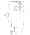
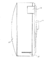
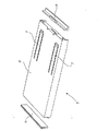
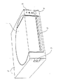
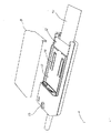
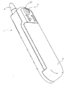
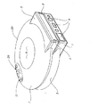
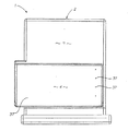
図面において、全般的に2で示すケーシングを含む印刷装置用の、第9の本発明の態様によるカートリッジ1を示す。図示する好ましい形態において、ケーシングを、2つの主部に分けるが、これは、用紙およびその類のシートを格納するための印刷媒体供給部3、およびインク供給器を格納するための第2収納部4から構成される。このカートリッジは、デジタル式印刷装置で使用するように設計し、特にドロップオンデマンド方式のインクジェット印刷装置に適している。
In the drawing, a
またケーシング2は、印刷媒体出口開口部5を画成するが、この開口部は、印刷媒体収納部3、および全般的に7で示す印刷媒体給送機構と繋がっている。給送機構は、印刷媒体供給口5に隣接する印刷媒体格納部3内に配置される。動作時、印刷媒体8を摘み上げ、印刷媒体出口開口部を介して外に印刷媒体8を駆動する。
The
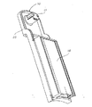
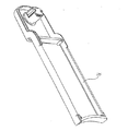
まず、カートリッジの印刷媒体収納部の要素を考慮すると、底部型枠11に対応して係止する媒体上部成型10から構成されることがわかる。このようにして、型枠は、一般的に矩形の印刷媒体収納領域12を画成するよう組み合うが、この領域において、印刷媒体は、階層状のシート用紙あるいはカードの形態で格納する。
First, considering the elements of the print medium storage portion of the cartridge, it can be seen that the medium
型枠10および11の上部および底部は、組み合わせて、印刷媒体出口開口部5を画成するように前部に両方とも構成される。使用上において、積層するカード8は収納領域12内に配置される。これらは、底部型枠11の上面14との接合方向に、薄金属ばね15によって、下方向に付勢されるが、このばねは、上部型枠10の内部の下層面16に対向している。
The top and bottom of the
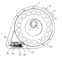
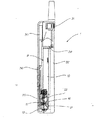
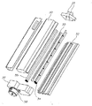
図示する好ましい形態の印刷媒体給送機構は、噛合ピックアップローラ組立品18の形態を取る。この組立品は、駆動軸19、駆動軸に固定されるピックアップローラ20、および外部駆動歯車21を含む。
The preferred form of print media feeding mechanism shown takes the form of an interlocking pick-up
給送組立品18は、上部および底部印刷媒体型枠によって形成されるケーシング部内に係留され、駆動軸19は、出口開口部5下に位置する溝路23に形成される動作リブ22によって回動可能なように支持される。上部型枠によって、ピックアップローラ20を保持する駆動軸部を完全に囲うが、外部変速機21は示すように露出したままである。他の形態において、駆動歯車は、印刷装置上の対応する電動ローラと係合するために、ケーシング内の開口部を介してアクセスしてもよい。またプラスチックあるいは金属箔25は、出口開口部5に隣接して設けられる。この箔は、一旦給送機構が動作すると用紙あるいはカードが1枚だけ出口を介して一回毎に供給されるように、出口を横切って下方向に延びるように大きさを決定する。
The feeding
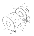
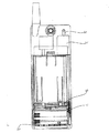
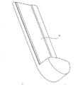
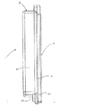
同様に、インク収納部4は、カートリッジケーシングの一部を形成する2つの個別の型枠によって画成される。元々の型枠は、複数の個別のインク小室27を画成するよう設計されたインク収納母体型枠26である。最終的には、小室がこの母体型枠26の蓋型枠との直接あるいは間接の接続によって封止されるが、これは、この好ましい形態において、印刷媒体収納底部型枠11の下側28に設けられる。
Similarly, the
図示された好ましい形態において、中間の薄い仕切り変形可能な膜30を設けるため、2つの型枠の接続は間接的であるが、この膜は、好ましくは、母体型枠26に画成されるインク小室27内に入れ子になるように当初縁取られる。組付中に、母体型枠26は、薄い仕切られる変形可能な膜30の末端部付近に設けられるフランジ31と気密接続され、次にこの膜は、印刷媒体収納底部型枠11の下側28と気密接続される。
In the preferred form shown, the connection of the two molds is indirect to provide an intermediate thin
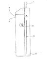
図面からわかるように、インク小室母体型枠27は、インク供給接続連結管領域32を画成するように、印刷媒体収納領域上方の周辺縁を超えて延在することが好ましい。連結管32の上部は、印刷媒体収納底部型枠11の拡張部33として形成され、そこに複数のインク接続ノズル34が含まれるが、このノズルは、孔の開いたインク封止35によって閉じられている。使用上、インクは、変形可能な膜上方に収納し、それによって、インク接続ノズル34と流体的に連通する。インクが消耗されるにつれて、変形可能な膜30が折り畳まれ易くするために、空気抜き孔37は、インク収納母体型枠26に、好ましくは、インクノズルから離れた端面に設ける。カートリッジケーシングの様々な構成要素は、粘着物の使用、超音波溶接、あるいは機械的連結等を含む適切な手段によって、組み立てられる。
As can be seen from the drawing, the ink
以上述べてきたように、本発明のカートリッジの好ましい適用例は、オーストラリア仮特許出願PP7020、および関連する米国出願、本明細書と同時出願の、表題「内蔵印刷装置付きビデオゲーム操作」の中で述べられている類の一体型プリンタを有するビデオゲーム操作用であり、これらの内容を本明細書中に参照のため引用する。 As mentioned above, a preferred application of the cartridge of the present invention is in the Australian provisional patent application PP7020 and related US application, co-pending application, entitled “Video Game Operation with Built-in Printing Device”. For video game operations having an integrated printer of the type described, the contents of which are hereby incorporated by reference.
使用上において、本発明のカートリッジは、適切に設計された印刷装置内に挿入され、それによって、駆動歯車21は、印刷装置上に設けられた対応する被駆動歯車と位置合わせされ係合する。この設計は利点を多く有する。最も重要な点は、機構および印刷媒体を密閉されたユニット内に格納するため、カートリッジ内に給送手段を備えることによって、用紙あるいは他の印刷媒体を、カートリッジの外に正確に、最小の初期汚れで、確実に供給できる。従来技術のカートリッジにおいては、カートリッジは、印刷装置に取り付けられるピックアップローラ上に圧迫され、これによって用紙が下側に露出する。対照的に、本発明に従う設計によれば、印刷媒体を同程度露出する開口部を設ける必要がないために、構造上の保全性がより高まる。更に、この設計によって、不正変更保護ユニットが提供される。
In use, the cartridge of the present invention is inserted into a suitably designed printing device, whereby the
これら好ましい形態に関する追加的な利点は、インク供給口ノズル上を覆う封止を備えることを含むが、このノズルは、装填の際に印刷装置によって自動的に孔を開けることが可能である。この点において、カートリッジは、一回のみ使用される製品としてのみ意図される。更にインク小室型枠の構造は、これによって、変形可能な膜および基礎が、同時動作で成型あるいは連結して、完全に封止されたインク小室を形成するが、製造上のコストおよび効率面の利点を明瞭に提供する。 Additional advantages associated with these preferred forms include providing a seal over the ink supply nozzle, which can be automatically pierced by the printing device upon loading. In this respect, the cartridge is intended only as a product that is used only once. Further, the structure of the ink chamber mold allows the deformable membrane and foundation to be molded or joined together in a simultaneous operation to form a completely sealed ink chamber, but in terms of manufacturing cost and efficiency. Provide benefits clearly.
印刷媒体給送機構は、ピックアップローラ機構に限定する必要はないが、カートリッジケーシングの外側から外部駆動できる、あらゆる他の適切な機構を含むことができる。同様に、インクの貯留手段は、既述の形態に限定せず、他の変形可能な、あるいは変形不可の収納手段の使用方法を含むことができる。 The print media feed mechanism need not be limited to a pickup roller mechanism, but can include any other suitable mechanism that can be driven externally from the outside of the cartridge casing. Similarly, the ink storage means is not limited to the above-described form, and may include other use methods of the storage means that can be deformed or cannot be deformed.
本発明について、具体例を参照して述べてきたが、それらは多くの他の形態に各々具体化できることは理解されるであろう。 Although the invention has been described with reference to specific examples, it will be understood that they can each be embodied in many other forms.
Claims (12)
粘着剤が塗布された印刷媒体の供給器を格納するための第1容器部とインク供給器を収納するための第2容器部とを画成するカートリッジケーシングを含むことを特徴とする印刷装置用カートリッジ。 A printing apparatus cartridge, wherein the printing apparatus cartridge is:
A printing apparatus comprising: a cartridge casing that defines a first container portion for storing a supply device for a printing medium coated with an adhesive and a second container portion for storing an ink supply device. cartridge.
前記第1容器部は、ロール状の連続的な裏地材料におけるステッカ材料から構成される印刷ロールの形態で、粘着剤が塗布されたステッカ材料を保持するように構成されることを特徴とする印刷装置用カートリッジ。 The cartridge for a printing apparatus according to claim 1,
The first container portion is configured to hold a sticker material coated with an adhesive in the form of a printing roll composed of a sticker material in a continuous continuous roll material. Device cartridge.
前記インク収納容器は、異なる色のインクを収納するために複数の個別の小室に分割されていることを特徴とする印刷装置用カートリッジ。 The cartridge for a printing apparatus according to claim 1,
The cartridge for a printing apparatus, wherein the ink storage container is divided into a plurality of individual chambers for storing different color inks.
前記インク収納容器は、設置に際して、印刷装置によって、孔を開けることが可能な、1つ以上のインク注出口を含むことを特徴とする印刷装置用カートリッジ。 The cartridge for a printing apparatus according to claim 1,
A cartridge for a printing apparatus, wherein the ink container includes one or more ink spouts that can be perforated by a printing apparatus when installed.
印刷装置によって識別が可能な認証手段を含むことを特徴とする印刷装置用カートリッジ。 The cartridge for a printing apparatus according to claim 1,
A cartridge for a printing apparatus, comprising authentication means that can be identified by the printing apparatus.
前記ステッカローラを収納するケーシング部は、環状であることを特徴とする印刷装置用カートリッジ。 The cartridge for a printing apparatus according to claim 1,
A cartridge for a printing apparatus, wherein a casing portion that houses the sticker roller is annular.
前記ステッカローラを収納するケーシング部は、環状であり、インク収納容器が前記ケーシング部から外側へ半径方向に延在することを特徴とする印刷装置用カートリッジ。 The cartridge for a printing apparatus according to claim 2,
A cartridge for a printing apparatus, wherein a casing portion for storing the sticker roller is annular, and an ink storage container extends radially outward from the casing portion.
ケーシングは、印刷装置にワンタッチで装着するよう構成されていることを特徴とする印刷装置用カートリッジ。 The cartridge for a printing apparatus according to claim 1,
A cartridge for a printing apparatus, wherein the casing is configured to be attached to the printing apparatus with a single touch.
ケーシングは、ステッカ出口開口部と、印刷装置からピックアップローラを受けるように構成された後続の開口部を含むことを特徴とする印刷装置用カートリッジ。 The cartridge for a printing apparatus according to claim 1,
The casing includes a sticker outlet opening and a subsequent opening configured to receive a pick-up roller from the printing apparatus.
ステッカ及びインク供給器は、同時に補充可能に構成されていることを特徴とする印刷装置用カートリッジ。 The cartridge for a printing apparatus according to claim 1,
The cartridge for a printing apparatus, wherein the sticker and the ink supply unit are configured to be replenished simultaneously.
ステッカ印刷デジタルカメラ装置に用いるように構成されていることを特徴とする印刷装置用カートリッジ。 The cartridge for a printing apparatus according to claim 1,
A cartridge for a printing apparatus configured to be used in a sticker printing digital camera apparatus.
前記粘着剤が塗布された印刷媒体と前記インク供給器とを含むことを特徴とする印刷装置用カートリッジ。 The cartridge for a printing apparatus according to claim 1,
A printing apparatus cartridge comprising: a printing medium coated with the pressure-sensitive adhesive; and the ink supply unit.
Applications Claiming Priority (6)
| Application Number | Priority Date | Filing Date | Title |
|---|---|---|---|
| AUPP7020A AUPP702098A0 (en) | 1998-11-09 | 1998-11-09 | Image creation method and apparatus (ART73) |
| AUPP7021A AUPP702198A0 (en) | 1998-11-09 | 1998-11-09 | Image creation method and apparatus (ART79) |
| AUPP7027A AUPP702798A0 (en) | 1998-11-09 | 1998-11-09 | Image creation method and apparatus (ART70) |
| AUPP7026A AUPP702698A0 (en) | 1998-11-09 | 1998-11-09 | Image creation method and apparatus(ART78) |
| AUPP7017A AUPP701798A0 (en) | 1998-11-09 | 1998-11-09 | Image creation method and apparatus (ART75) |
| AUPP7019A AUPP701998A0 (en) | 1998-11-09 | 1998-11-09 | Image creation method and apparatus (ART74) |
Related Parent Applications (1)
| Application Number | Title | Priority Date | Filing Date |
|---|---|---|---|
| JP2000581504A Division JP4673976B2 (en) | 1998-11-09 | 1999-11-09 | Handheld sticker printing digital camera device |
Publications (2)
| Publication Number | Publication Date |
|---|---|
| JP2010069882A true JP2010069882A (en) | 2010-04-02 |
| JP4654310B2 JP4654310B2 (en) | 2011-03-16 |
Family
ID=27542971
Family Applications (6)
| Application Number | Title | Priority Date | Filing Date |
|---|---|---|---|
| JP2000581504A Expired - Fee Related JP4673976B2 (en) | 1998-11-09 | 1999-11-09 | Handheld sticker printing digital camera device |
| JP2009265581A Expired - Fee Related JP4658219B2 (en) | 1998-11-09 | 2009-11-20 | Printer unit for personal computer type disk drive bay |
| JP2009265583A Expired - Fee Related JP4782224B2 (en) | 1998-11-09 | 2009-11-20 | Handheld mobile phone device with printing device |
| JP2009265584A Expired - Fee Related JP4658220B2 (en) | 1998-11-09 | 2009-11-20 | Cartridge for digital printer |
| JP2009265582A Expired - Fee Related JP4654311B2 (en) | 1998-11-09 | 2009-11-20 | Handheld mobile phone device with printing device and print medium for supply |
| JP2009265580A Expired - Fee Related JP4654310B2 (en) | 1998-11-09 | 2009-11-20 | Cartridge for printing device |
Family Applications Before (5)
| Application Number | Title | Priority Date | Filing Date |
|---|---|---|---|
| JP2000581504A Expired - Fee Related JP4673976B2 (en) | 1998-11-09 | 1999-11-09 | Handheld sticker printing digital camera device |
| JP2009265581A Expired - Fee Related JP4658219B2 (en) | 1998-11-09 | 2009-11-20 | Printer unit for personal computer type disk drive bay |
| JP2009265583A Expired - Fee Related JP4782224B2 (en) | 1998-11-09 | 2009-11-20 | Handheld mobile phone device with printing device |
| JP2009265584A Expired - Fee Related JP4658220B2 (en) | 1998-11-09 | 2009-11-20 | Cartridge for digital printer |
| JP2009265582A Expired - Fee Related JP4654311B2 (en) | 1998-11-09 | 2009-11-20 | Handheld mobile phone device with printing device and print medium for supply |
Country Status (10)
| Country | Link |
|---|---|
| EP (1) | EP1129388A4 (en) |
| JP (6) | JP4673976B2 (en) |
| KR (7) | KR100698369B1 (en) |
| CN (8) | CN100526978C (en) |
| AU (4) | AU768978B2 (en) |
| BR (1) | BR9915168A (en) |
| CA (1) | CA2347168A1 (en) |
| ID (1) | ID29171A (en) |
| IL (13) | IL162282A0 (en) |
| WO (1) | WO2000028379A1 (en) |
Cited By (2)
| Publication number | Priority date | Publication date | Assignee | Title |
|---|---|---|---|---|
| JP2019112170A (en) * | 2017-12-22 | 2019-07-11 | 富士通コンポーネント株式会社 | Recording paper cassette |
| JP2022010158A (en) * | 2017-12-22 | 2022-01-14 | 富士通コンポーネント株式会社 | Recording paper cassette |
Families Citing this family (52)
| Publication number | Priority date | Publication date | Assignee | Title |
|---|---|---|---|---|
| US6769128B1 (en) | 1995-06-07 | 2004-07-27 | United Video Properties, Inc. | Electronic television program guide schedule system and method with data feed access |
| US6786420B1 (en) | 1997-07-15 | 2004-09-07 | Silverbrook Research Pty. Ltd. | Data distribution mechanism in the form of ink dots on cards |
| US6618117B2 (en) | 1997-07-12 | 2003-09-09 | Silverbrook Research Pty Ltd | Image sensing apparatus including a microcontroller |
| US6948794B2 (en) | 1997-07-15 | 2005-09-27 | Silverbrook Reserach Pty Ltd | Printhead re-capping assembly for a print and demand digital camera system |
| US6624848B1 (en) | 1997-07-15 | 2003-09-23 | Silverbrook Research Pty Ltd | Cascading image modification using multiple digital cameras incorporating image processing |
| US6879341B1 (en) | 1997-07-15 | 2005-04-12 | Silverbrook Research Pty Ltd | Digital camera system containing a VLIW vector processor |
| US6986613B2 (en) | 1997-07-15 | 2006-01-17 | Silverbrook Research Pty Ltd | Keyboard |
| US6641315B2 (en) | 1997-07-15 | 2003-11-04 | Silverbrook Research Pty Ltd | Keyboard |
| US6690419B1 (en) | 1997-07-15 | 2004-02-10 | Silverbrook Research Pty Ltd | Utilising eye detection methods for image processing in a digital image camera |
| US7110024B1 (en) | 1997-07-15 | 2006-09-19 | Silverbrook Research Pty Ltd | Digital camera system having motion deblurring means |
| ES2475242T3 (en) | 1997-07-21 | 2014-07-10 | Gemstar Development Corporation | Systems and methods for displaying and recording control interfaces |
| US6508546B2 (en) * | 1998-10-16 | 2003-01-21 | Silverbrook Research Pty Ltd | Ink supply arrangement for a portable ink jet printer |
| US6733116B1 (en) | 1998-10-16 | 2004-05-11 | Silverbrook Research Pty Ltd | Ink jet printer with print roll and printhead assemblies |
| CN1867068A (en) | 1998-07-14 | 2006-11-22 | 联合视频制品公司 | Client-server based interactive television program guide system with remote server recording |
| US6898762B2 (en) | 1998-08-21 | 2005-05-24 | United Video Properties, Inc. | Client-server electronic program guide |
| AUPP702098A0 (en) | 1998-11-09 | 1998-12-03 | Silverbrook Research Pty Ltd | Image creation method and apparatus (ART73) |
| US6906778B2 (en) | 1998-11-09 | 2005-06-14 | Silverbrook Research Pty Ltd | Image recordal and generation apparatus |
| US7014307B2 (en) | 1998-11-09 | 2006-03-21 | Silverbrook Research Pty Ltd | Printing unit for an image recordal and generation apparatus |
| US7154580B2 (en) | 1998-11-09 | 2006-12-26 | Silverbrook Research Pty Ltd | Image recordal and generation apparatus |
| AUPQ056099A0 (en) | 1999-05-25 | 1999-06-17 | Silverbrook Research Pty Ltd | A method and apparatus (pprint01) |
| US7407257B2 (en) | 1999-05-25 | 2008-08-05 | Silverbrook Research Pty Ltd | Mobile device including a force transfer mechanism |
| CN101707693B (en) | 2000-10-11 | 2017-04-26 | 乐威指南公司 | Systems and methods for providing storage of data on servers in an on-demand media delivery system |
| AU2002214851B2 (en) * | 2000-12-21 | 2004-07-22 | Silverbrook Research Pty Ltd | Digital photo album with internal printer |
| CN1191940C (en) * | 2000-12-29 | 2005-03-09 | 西尔弗布鲁克研究有限公司 | Print cartridge with air filtering means |
| AUPR256401A0 (en) * | 2001-01-17 | 2001-02-08 | Silverbrook Research Pty. Ltd. | An apparatus (AP17) |
| AUPR256601A0 (en) | 2001-01-17 | 2001-02-08 | Silverbrook Research Pty. Ltd. | An apparatus (AP29) |
| AUPR256301A0 (en) | 2001-01-17 | 2001-02-08 | Silverbrook Research Pty. Ltd. | An apparatus (AP15) |
| KR101548473B1 (en) | 2001-02-21 | 2015-08-28 | 로비 가이드스, 인크. | Systems and methods for interactive program guides with personal video recording features |
| JP4532767B2 (en) * | 2001-03-21 | 2010-08-25 | キヤノン株式会社 | Media pack and inkjet recording apparatus |
| US6648533B2 (en) | 2001-06-29 | 2003-11-18 | Hewlett-Packard Development Company, L.P. | Label-making inkjet printer |
| AU2005202922B2 (en) * | 2001-08-31 | 2006-10-19 | Zamtec Limited | A printhead assembly for an ink jet printer |
| AU2006252321B2 (en) * | 2001-08-31 | 2007-06-14 | Zamtec Limited | An ink jet printer with print medium and ink cartridge |
| US20030086109A1 (en) * | 2001-11-08 | 2003-05-08 | Fitch Catherine Jo | Printer help apparatus and method |
| AUPS047802A0 (en) * | 2002-02-13 | 2002-03-07 | Silverbrook Research Pty. Ltd. | Methods and systems (AP69) |
| AUPS049302A0 (en) | 2002-02-13 | 2002-03-07 | Silverbrook Research Pty. Ltd. | Methods and systems (ap53) |
| AUPS047702A0 (en) | 2002-02-13 | 2002-03-07 | Silverbrook Research Pty. Ltd. | Methods and systems (ap68) |
| US7431427B2 (en) | 2002-06-13 | 2008-10-07 | Silverbrook Research Pty Ltd | Ink supply arrangement with improved ink flows |
| JP2004117995A (en) * | 2002-09-27 | 2004-04-15 | Nec Mobiling Ltd | Image printing system using portable telephone with camera |
| US7493646B2 (en) | 2003-01-30 | 2009-02-17 | United Video Properties, Inc. | Interactive television systems with digital video recording and adjustable reminders |
| US7801888B2 (en) | 2007-03-09 | 2010-09-21 | Microsoft Corporation | Media content search results ranked by popularity |
| US10063934B2 (en) | 2008-11-25 | 2018-08-28 | Rovi Technologies Corporation | Reducing unicast session duration with restart TV |
| US9166714B2 (en) | 2009-09-11 | 2015-10-20 | Veveo, Inc. | Method of and system for presenting enriched video viewing analytics |
| US9014546B2 (en) | 2009-09-23 | 2015-04-21 | Rovi Guides, Inc. | Systems and methods for automatically detecting users within detection regions of media devices |
| ITUD20110072A1 (en) * | 2011-05-13 | 2012-11-14 | Giacomo Battiston | DEVICE FOR PLAYING IMAGES OR GRAPHIC REASONS ON SURFACES, AND ITS PROCEDURE |
| US9225853B2 (en) * | 2011-08-17 | 2015-12-29 | Empire Technology Development Llc | Visual images processed on portions of folded substrate |
| US8805418B2 (en) | 2011-12-23 | 2014-08-12 | United Video Properties, Inc. | Methods and systems for performing actions based on location-based rules |
| CN102658732A (en) * | 2012-05-31 | 2012-09-12 | 广州市宝比塑料制品有限公司 | Printer |
| JP7014531B2 (en) * | 2017-06-21 | 2022-02-01 | 富士通コンポーネント株式会社 | Printing equipment |
| JP7148251B2 (en) * | 2018-03-23 | 2022-10-05 | 富士通コンポーネント株式会社 | Recording paper cassette and printer device |
| JP1634604S (en) * | 2018-09-03 | 2019-06-24 | Tape printing machine | |
| JP7188059B2 (en) * | 2018-12-21 | 2022-12-13 | ブラザー工業株式会社 | printer |
| CN113438241B (en) * | 2021-06-25 | 2024-02-13 | 佳缘科技股份有限公司 | Data transmission method and system |
Citations (7)
| Publication number | Priority date | Publication date | Assignee | Title |
|---|---|---|---|---|
| JPH02302181A (en) * | 1989-05-17 | 1990-12-14 | Minolta Camera Co Ltd | Camera with printer |
| JPH06183117A (en) * | 1992-12-17 | 1994-07-05 | Casio Comput Co Ltd | Printing cassette and printing device |
| JPH082754A (en) * | 1994-06-22 | 1996-01-09 | Matsushita Graphic Commun Syst Inc | Ink jet recording device |
| JPH0890879A (en) * | 1994-09-28 | 1996-04-09 | Brother Ind Ltd | Cassette case for preparing printing tape, and printing tape preparing apparatus |
| JPH08276600A (en) * | 1995-03-29 | 1996-10-22 | Hewlett Packard Co <Hp> | Ink replenishment system and method of ink jet printer |
| JPH09116843A (en) * | 1995-10-20 | 1997-05-02 | Canon Inc | Image pickup device with printer |
| JPH10183U (en) * | 1997-09-29 | 1998-08-25 | セイコーエプソン株式会社 | Tape printer |
Family Cites Families (43)
| Publication number | Priority date | Publication date | Assignee | Title |
|---|---|---|---|---|
| JPS5739387Y2 (en) * | 1977-01-05 | 1982-08-30 | ||
| JPS60204361A (en) * | 1984-03-30 | 1985-10-15 | Canon Inc | Ink tank of ink jet recording apparatus |
| US4904100A (en) * | 1988-12-05 | 1990-02-27 | Eastman Kodak Company | Cartridge and printer system for using roll print media |
| JPH0314879A (en) * | 1989-06-13 | 1991-01-23 | Seiko Epson Corp | Coating composition |
| US5020926A (en) * | 1990-06-08 | 1991-06-04 | Sejus Corporation | Printer mounting arrangement |
| JP3120448B2 (en) * | 1990-11-29 | 2000-12-25 | ミノルタ株式会社 | Still video camera system |
| US5493409A (en) * | 1990-11-29 | 1996-02-20 | Minolta Camera Kabushiki Kaisha | Still video camera having a printer capable of printing a photographed image in a plurality of printing modes |
| JP2571162B2 (en) * | 1991-03-15 | 1997-01-16 | 松下電器産業株式会社 | Mobile phone equipment |
| JPH0516377A (en) * | 1991-07-08 | 1993-01-26 | Seiko Epson Corp | Ink cartridge |
| GB2256519A (en) * | 1991-06-08 | 1992-12-09 | Nationwide Lotteries Limited | Lottery/gaming apparatus and methods |
| US5625669A (en) * | 1991-09-27 | 1997-04-29 | Telemac Cellular Corporation | Mobile phone with internal call accounting controls |
| KR940003112B1 (en) * | 1991-10-25 | 1994-04-13 | 삼성전자 주식회사 | Cassette for feeding papers in a copier |
| WO1993010506A1 (en) * | 1991-11-22 | 1993-05-27 | Engineered Data Products, Inc. | Label generation apparatus |
| JPH05201081A (en) * | 1992-01-27 | 1993-08-10 | Canon Inc | Sheet feeder and recording device using same |
| JPH05330150A (en) * | 1992-06-03 | 1993-12-14 | Matsushita Electric Ind Co Ltd | Printer |
| US5595447A (en) * | 1992-10-13 | 1997-01-21 | Seiko Epson Corporation | Tape cartridge and printing device having print medium cartridge |
| JPH06149051A (en) * | 1992-11-08 | 1994-05-27 | Ricoh Co Ltd | Developer container, processing cartridge, judgement device for recycling of such container or cartridge and image forming device |
| JP3133906B2 (en) * | 1993-08-19 | 2001-02-13 | キヤノン株式会社 | Ink tank cartridge |
| JPH07219689A (en) * | 1994-01-31 | 1995-08-18 | Hitachi Ltd | Printer and system used therefor |
| US5665249A (en) * | 1994-10-17 | 1997-09-09 | Xerox Corporation | Micro-electromechanical die module with planarized thick film layer |
| EP0710561B1 (en) * | 1994-11-07 | 2002-04-10 | Canon Aptex Inc. | Printer and ink cartridge to be employed in the same |
| JPH08185541A (en) * | 1994-12-28 | 1996-07-16 | Casio Comput Co Ltd | Image controller with printer |
| US5719936A (en) * | 1995-03-07 | 1998-02-17 | Siemens Aktiengesellschaft | Communication device for mobile operation having a telephone and notebook with display |
| AUPN234695A0 (en) * | 1995-04-12 | 1995-05-04 | Eastman Kodak Company | Heater structure for monolithic lift print heads |
| US5664013A (en) * | 1995-06-07 | 1997-09-02 | Compaq Computer Corporation | Embedded notepad system for a cellular telephone |
| KR970000595A (en) * | 1995-06-13 | 1997-01-21 | 구자홍 | HEAD GAP ADJUSTMENT FOR INK JET PRINTER |
| WO1997004353A1 (en) * | 1995-07-14 | 1997-02-06 | Chumbley Gregory R | Postage and photo vending apparatus |
| JPH0936941A (en) * | 1995-07-24 | 1997-02-07 | Mitsubishi Electric Corp | Portable telephone system |
| CN2241563Y (en) * | 1995-08-25 | 1996-12-04 | 张迎霄 | Printing card machine |
| JP3715695B2 (en) * | 1995-08-29 | 2005-11-09 | キヤノン株式会社 | Compound camera |
| JPH09113990A (en) * | 1995-10-17 | 1997-05-02 | Fuji Photo Film Co Ltd | Device for taking photograph for certificate |
| US5634169A (en) * | 1996-02-16 | 1997-05-27 | Lexmark International, Inc. | Multiple function encoder wheel for cartridges utilized in an electrophotographic output device |
| JPH09267487A (en) * | 1996-04-03 | 1997-10-14 | Canon Inc | Ink tank for recording head, recording head cartridge, and recorder using the recording head |
| CA2230123A1 (en) * | 1996-06-25 | 1997-12-31 | Casio Computer Co., Ltd. | Printing apparatus and printing system |
| US5784959A (en) * | 1996-07-09 | 1998-07-28 | Larios; Frank N. | Hand-held printer and method for adhesive tape |
| JPH1058758A (en) * | 1996-08-20 | 1998-03-03 | Brother Ind Ltd | Scanning printer |
| JPH1065780A (en) * | 1996-08-22 | 1998-03-06 | Hitachi Ltd | Portable telephone equipment with video telephone function |
| JPH10112855A (en) * | 1996-10-07 | 1998-04-28 | Kinya Matsumoto | Portable device for automatically transmitting |
| JPH10164538A (en) * | 1996-11-28 | 1998-06-19 | Fumiaki Kitazawa | Portable video telephone set by digital image-processing of various television cameras in ccd image element capable of utilizing ic chip charge card |
| US5757388A (en) * | 1996-12-16 | 1998-05-26 | Eastman Kodak Company | Electronic camera and integral ink jet printer |
| JP3664202B2 (en) * | 1997-02-24 | 2005-06-22 | 富士写真フイルム株式会社 | Color thermal printer |
| JP4447163B2 (en) | 1997-07-15 | 2010-04-07 | シルバーブルック リサーチ ピーティワイ リミテッド | Portable camera system and system for authenticating supply to portable camera system |
| US6459495B1 (en) | 1997-07-15 | 2002-10-01 | Silverbrook Research Pty Ltd | Dot center tracking in optical storage systems using ink dots |
-
1999
- 1999-11-09 IL IL16228299A patent/IL162282A0/en active IP Right Grant
- 1999-11-09 EP EP99957715A patent/EP1129388A4/en not_active Withdrawn
- 1999-11-09 AU AU15337/00A patent/AU768978B2/en not_active Ceased
- 1999-11-09 IL IL16228199A patent/IL162281A0/en active IP Right Grant
- 1999-11-09 CN CNB2004100472117A patent/CN100526978C/en not_active Expired - Fee Related
- 1999-11-09 CA CA002347168A patent/CA2347168A1/en not_active Abandoned
- 1999-11-09 CN CN2004100472070A patent/CN1550878B/en not_active Expired - Fee Related
- 1999-11-09 CN CN2004100472085A patent/CN1550879B/en not_active Expired - Fee Related
- 1999-11-09 CN CNA2004100472102A patent/CN1550881A/en active Pending
- 1999-11-09 KR KR1020017005869A patent/KR100698369B1/en not_active IP Right Cessation
- 1999-11-09 IL IL16227999A patent/IL162279A0/en active IP Right Grant
- 1999-11-09 BR BR9915168-5A patent/BR9915168A/en not_active Application Discontinuation
- 1999-11-09 IL IL16228099A patent/IL162280A0/en unknown
- 1999-11-09 ID IDW00200101034A patent/ID29171A/en unknown
- 1999-11-09 CN CNB200410047209XA patent/CN100436132C/en not_active Expired - Fee Related
- 1999-11-09 CN CNB2004100472121A patent/CN100478778C/en not_active Expired - Fee Related
- 1999-11-09 JP JP2000581504A patent/JP4673976B2/en not_active Expired - Fee Related
- 1999-11-09 IL IL14271599A patent/IL142715A/en not_active IP Right Cessation
- 1999-11-09 WO PCT/AU1999/000985 patent/WO2000028379A1/en active Search and Examination
- 1999-11-09 CN CNB998130834A patent/CN1184529C/en not_active Expired - Fee Related
- 1999-11-09 KR KR10-2004-7016331A patent/KR20040097350A/en not_active Application Discontinuation
- 1999-11-09 IL IL16227899A patent/IL162278A0/en active IP Right Grant
- 1999-11-09 KR KR10-2004-7016329A patent/KR20040102088A/en not_active Application Discontinuation
- 1999-11-09 KR KR1020047016326A patent/KR100699251B1/en not_active IP Right Cessation
- 1999-11-09 IL IL16227799A patent/IL162277A0/en unknown
- 1999-11-09 KR KR10-2004-7016327A patent/KR20040101462A/en not_active Application Discontinuation
- 1999-11-09 CN CN200410094607A patent/CN100587590C/en not_active Expired - Fee Related
- 1999-11-09 KR KR1020047016328A patent/KR100636627B1/en not_active IP Right Cessation
- 1999-11-09 KR KR10-2004-7016332A patent/KR20040101464A/en not_active Application Discontinuation
-
2004
- 2004-02-11 AU AU2004200514A patent/AU2004200514B2/en not_active Ceased
- 2004-02-11 AU AU2004200517A patent/AU2004200517B2/en not_active Ceased
- 2004-02-11 AU AU2004200510A patent/AU2004200510B2/en not_active Ceased
- 2004-06-01 IL IL162277A patent/IL162277A/en not_active IP Right Cessation
- 2004-06-01 IL IL162278A patent/IL162278A/en not_active IP Right Cessation
- 2004-06-01 IL IL162279A patent/IL162279A/en not_active IP Right Cessation
- 2004-06-01 IL IL162280A patent/IL162280A/en not_active IP Right Cessation
- 2004-06-01 IL IL162281A patent/IL162281A/en not_active IP Right Cessation
- 2004-06-01 IL IL162282A patent/IL162282A/en not_active IP Right Cessation
-
2009
- 2009-11-20 JP JP2009265581A patent/JP4658219B2/en not_active Expired - Fee Related
- 2009-11-20 JP JP2009265583A patent/JP4782224B2/en not_active Expired - Fee Related
- 2009-11-20 JP JP2009265584A patent/JP4658220B2/en not_active Expired - Fee Related
- 2009-11-20 JP JP2009265582A patent/JP4654311B2/en not_active Expired - Fee Related
- 2009-11-20 JP JP2009265580A patent/JP4654310B2/en not_active Expired - Fee Related
Patent Citations (7)
| Publication number | Priority date | Publication date | Assignee | Title |
|---|---|---|---|---|
| JPH02302181A (en) * | 1989-05-17 | 1990-12-14 | Minolta Camera Co Ltd | Camera with printer |
| JPH06183117A (en) * | 1992-12-17 | 1994-07-05 | Casio Comput Co Ltd | Printing cassette and printing device |
| JPH082754A (en) * | 1994-06-22 | 1996-01-09 | Matsushita Graphic Commun Syst Inc | Ink jet recording device |
| JPH0890879A (en) * | 1994-09-28 | 1996-04-09 | Brother Ind Ltd | Cassette case for preparing printing tape, and printing tape preparing apparatus |
| JPH08276600A (en) * | 1995-03-29 | 1996-10-22 | Hewlett Packard Co <Hp> | Ink replenishment system and method of ink jet printer |
| JPH09116843A (en) * | 1995-10-20 | 1997-05-02 | Canon Inc | Image pickup device with printer |
| JPH10183U (en) * | 1997-09-29 | 1998-08-25 | セイコーエプソン株式会社 | Tape printer |
Cited By (4)
| Publication number | Priority date | Publication date | Assignee | Title |
|---|---|---|---|---|
| JP2019112170A (en) * | 2017-12-22 | 2019-07-11 | 富士通コンポーネント株式会社 | Recording paper cassette |
| JP2022010158A (en) * | 2017-12-22 | 2022-01-14 | 富士通コンポーネント株式会社 | Recording paper cassette |
| JP7044539B2 (en) | 2017-12-22 | 2022-03-30 | 富士通コンポーネント株式会社 | Recording paper cassette |
| JP7244608B2 (en) | 2017-12-22 | 2023-03-22 | 富士通コンポーネント株式会社 | Recording paper cassette |
Also Published As
Similar Documents
| Publication | Publication Date | Title |
|---|---|---|
| JP4658219B2 (en) | Printer unit for personal computer type disk drive bay | |
| RU2249240C2 (en) | Printing camera for printing on gummed paper | |
| AU2004200512B2 (en) | A printer unit for a computer disk drive bay | |
| AU2006348291B2 (en) | Digital photo frame with integral printer | |
| JP2003143513A (en) | Recorder with printer |
Legal Events
| Date | Code | Title | Description |
|---|---|---|---|
| A131 | Notification of reasons for refusal |
Free format text: JAPANESE INTERMEDIATE CODE: A131 Effective date: 20100406 |
|
| A521 | Request for written amendment filed |
Free format text: JAPANESE INTERMEDIATE CODE: A523 Effective date: 20100625 |
|
| TRDD | Decision of grant or rejection written | ||
| A01 | Written decision to grant a patent or to grant a registration (utility model) |
Free format text: JAPANESE INTERMEDIATE CODE: A01 Effective date: 20101207 |
|
| A01 | Written decision to grant a patent or to grant a registration (utility model) |
Free format text: JAPANESE INTERMEDIATE CODE: A01 |
|
| A61 | First payment of annual fees (during grant procedure) |
Free format text: JAPANESE INTERMEDIATE CODE: A61 Effective date: 20101220 |
|
| R150 | Certificate of patent or registration of utility model |
Free format text: JAPANESE INTERMEDIATE CODE: R150 |
|
| FPAY | Renewal fee payment (event date is renewal date of database) |
Free format text: PAYMENT UNTIL: 20131224 Year of fee payment: 3 |
|
| R350 | Written notification of registration of transfer |
Free format text: JAPANESE INTERMEDIATE CODE: R350 |
|
| LAPS | Cancellation because of no payment of annual fees | ||
| R350 | Written notification of registration of transfer |
Free format text: JAPANESE INTERMEDIATE CODE: R350 |