JP2010064634A - Manufacturing method of structure for railroad car by friction stir joining - Google Patents
Manufacturing method of structure for railroad car by friction stir joining Download PDFInfo
- Publication number
- JP2010064634A JP2010064634A JP2008233421A JP2008233421A JP2010064634A JP 2010064634 A JP2010064634 A JP 2010064634A JP 2008233421 A JP2008233421 A JP 2008233421A JP 2008233421 A JP2008233421 A JP 2008233421A JP 2010064634 A JP2010064634 A JP 2010064634A
- Authority
- JP
- Japan
- Prior art keywords
- friction stir
- double skin
- joint
- stir welding
- face plate
- Prior art date
- Legal status (The legal status is an assumption and is not a legal conclusion. Google has not performed a legal analysis and makes no representation as to the accuracy of the status listed.)
- Granted
Links
Images


Abstract
Description
本発明は、ボビンツール型をした摩擦攪拌接合用工具を使用してダブルスキンパネルを接合することにより鉄道車両用構体を製造するための製造方法に関し、特にダブルスキンパネルの面板同士を隙間無しで行う摩擦攪拌接合による鉄道車両用構体の製造方法に関する。 The present invention relates to a manufacturing method for manufacturing a structure for a railway vehicle by joining a double skin panel using a friction stir welding tool of a bobbin tool type, and in particular, there is no gap between face plates of the double skin panel. The present invention relates to a method of manufacturing a railway vehicle structure by friction stir welding.
新幹線車両などのような高速鉄道車両には、押出成形によって形成されたアルミニウム合金からなるダブルスキンパネルが使用され、その一定幅で長尺なダブルスキンパネル同士を接合することによって鉄道車両用構体が構成される。そして、そうした鉄道車両用構体の製造には、幅方向に突き合わせたダブルスキンパネルの面板同士を、摩擦攪拌によって接合する摩擦攪拌接合が利用されている。例えば、下記特許文献1には、図6に示すようにして行うダブルスキンパネルの摩擦攪拌接合についての記載がある(第1従来例)。 Double-skin panels made of aluminum alloy formed by extrusion molding are used for high-speed railway vehicles such as Shinkansen vehicles, and the structure for railway vehicles is formed by joining long double-skin panels with a certain width. Composed. In manufacturing such a structure for a railway vehicle, friction stir welding is used in which the face plates of the double skin panels that are butted in the width direction are joined together by friction stirring. For example, Patent Document 1 below describes a double-skin panel friction stir welding performed as shown in FIG. 6 (first conventional example).
同文献のダブルスキンパネル100A,100Bは、二面の平行な面板101,102と、両面を連結したリブ109によって構成され、端部リブ108から突き出した自由端の接合部111,112が形成されている。摩擦攪拌接合に当たっては、ダブルスキンパネル100A、100Bの両接合部111,112が突き合わされ、面板101,102同士が面一に配置される。そして、摩擦攪拌接合用工具であるボビンツール150を用いて、接合部111,112を一対のショルダで挟み込み、摩擦攪拌による接合が行われる。その際、接合部111,112の接合端面は、突き合わせ方向に直交して形成されており、突き合わせに際してギャップ120が生じることがある。そのため、接合部111,112はギャップ120を埋めることができるように肉厚に形成されている。
The
一方、下記特許文献2,3には、接合部の端面を傾斜面にしたダブルスキンパネルの摩擦攪拌接合について記載がある。特許文献2は、継手部分の上部開口を継手板で塞ぐものであって、その継手板を端面の傾斜を利用して蓋のように載せて設置することで、隙間による欠陥を生じ難くさせた摩擦攪拌接合である(第2従来例)。また、特許文献3は、ダブルスキンパネルが、両面板の接合部の接合端面を傾斜させ、一方が他方に嵌り込むように形成されている。そのため、ボビンツールの回転体による挟み込みによって、傾斜した接合端面同士が押し付けられ、両面に隙間が生じていたとしても、その隙間を閉じた摩擦攪拌接合が行われる(第3従来例)。
鉄道車両用構体を構成するダブルスキンパネルは、例えば20メートルもの長さを有するため、剛性の低い自由端である接合部は、長手方向に見た場合に、僅かではあるが板厚方向に歪みが生じていることがある。すると、図6に示すようにダブルスキンパネル100A,100Bの両接合部111,112の高さが揃っていない場合があり、そのまま摩擦攪拌接合を行えば仕上げ面に段差が残ってしまう。そこで、従来は、摩擦攪拌接合を行うに際し、20メートルの全長にわたって段差が生じている箇所を探し出し、ハンマーなどでたたいて高さを揃えるといった、煩わしい作業が必要であった。
The double-skin panel that constitutes a railway vehicle structure has a length of, for example, 20 meters. Therefore, the joint, which is a free end having low rigidity, is slightly distorted in the thickness direction when viewed in the longitudinal direction. May have occurred. Then, as shown in FIG. 6, there are cases where the heights of both
一方、第3従来例は、接合端面を傾斜させるダブルスキンパネルについて、接合の際にその接合端面に隙間を生じさせた接合方法が記載されている。すなわち、摩擦攪拌接合する一の面板側の突き合わせの際、他の面板側の接合端面間に隙間が空き、一の面板の熱収縮後もその開口量が適正であるような寸法で形成したダブルスキンパネルの接合方法が記載されている。
これに対して、本発明は、傾斜した接合端面間を有するダブルスキンパネルについて、その接合端面間の隙間を積極的に無くし、接合部の高さを揃える手間を軽減させた摩擦攪拌接合による鉄道車両用構体の製造方法を提供することを目的とする。
On the other hand, the third conventional example describes a joining method in which a gap is generated in the joining end face when joining the double skin panel in which the joining end face is inclined. In other words, when abutting on one face plate side to be friction stir welded, a double gap is formed with dimensions such that there is a gap between the joining end faces on the other face plate side and the opening amount is appropriate even after thermal shrinkage of one face plate. A skin panel joining method is described.
On the other hand, the present invention relates to a double-skin panel having a slanted joint end surface, a rail by friction stir welding that actively eliminates the gap between the joint end surfaces and reduces the labor of aligning the joint height. It aims at providing the manufacturing method of the structure for vehicles.
本発明に係る摩擦攪拌接合による鉄道車両用構体の製造方法は、鉄道車両用構体を構成する所定幅の長尺な一対の第1面板と第2面板とを幅方向に並んだ複数のリブによって連結したダブルスキンパネルが、幅方向端部にあって前記第1及び第2面板とほぼ直交する端部リブから前記第1及び第2面板が延長して突き出した接合部を有し、その接合部の接合端面には、同じ幅方向端部において前記第1及び第2面板とで異なる方向に傾斜した接合端面が形成されたものであって、幅方向に並べた2枚の前記ダブルスキンパネルについて、同方向に傾斜した接合端面同士を突き合わせ、両ダブルスキンパネルの接合部を、ボビンツール型をした摩擦攪拌接合用工具の一対の回転体によって挟み込み、その回転体の間の攪拌軸によって前記接合端面同士を突き合わせた接合部分を長手方向に沿って摩擦攪拌して接合するものであり、前記第1面板同士及び第2面板同士の前記接合部分について、前記ダブルスキンパネルの全長にわたって前記第1面板側及び第2面板側の両方に隙間が生じないように、前記ダブルスキンパネルを幅方向に荷重をかけた状態で固定し、その接合部分を摩擦攪拌接合用工具の一対の回転体によって挟んで押さえ込み、長手方向に沿って回転移動する攪拌軸によって摩擦攪拌して接合することを特徴とする。
また、本発明に係る摩擦攪拌接合による鉄道車両用構体の製造方法は、前記摩擦攪拌接合用工具の一対の回転体による接合部の押さえ込みは、前記ダブルスキンパネルに対する幅方向の荷重によって生じる前記接合端面の滑りによる接合部の変形を戻す大きさの荷重で行うことが好ましい。
A method for manufacturing a railway vehicle structure by friction stir welding according to the present invention includes a plurality of ribs in which a pair of long first face plates and second face plates having a predetermined width constituting the railway vehicle structure are arranged in the width direction. The connected double skin panel has a joint portion at the end portion in the width direction, in which the first and second face plates extend and protrude from end ribs that are substantially orthogonal to the first and second face plates. Two double skin panels arranged in the width direction are formed on the joint end face of the portion, and are formed with joint end faces inclined in different directions from the first and second face plates at the same width direction end. The joint end surfaces inclined in the same direction are butted together, and the joint portion of both double skin panels is sandwiched by a pair of rotating bodies of a friction stir welding tool having a bobbin tool type, and the stirring shaft between the rotating bodies Junction end The joined portions that are brought into contact with each other are frictionally agitated and joined along the longitudinal direction, and the joined portions of the first face plates and the second face plates are joined to the first face plate side over the entire length of the double skin panel. The double skin panel is fixed in a state where a load is applied in the width direction so that there is no gap on both sides of the second face plate, and the joint portion is sandwiched between a pair of rotating bodies of the friction stir welding tool and pressed down. The friction stir is performed by a stirring shaft that rotates and moves along the longitudinal direction.
Further, in the method of manufacturing a railway vehicle structure by friction stir welding according to the present invention, the pressing of the joint portion by the pair of rotating bodies of the friction stir welding tool is caused by the load in the width direction on the double skin panel. It is preferable to carry out with the load of the magnitude | size which returns the deformation | transformation of a junction part by the slip of an end surface.
本発明によれば、幅方向に荷重をかけてダブルスキンパネルを固定することにより、接合端面の傾斜面による板厚方向の分力によって同方向の歪みを修正するので、従来行っていた煩わしい修正作業を省略することができる。
また、摩擦攪拌接合時に接合部の変形を戻すようにボビンツールで押さえ込むので、仕上げの良い接合を行うことが可能である。
According to the present invention, since the double skin panel is fixed by applying a load in the width direction, the distortion in the same direction is corrected by the component force in the plate thickness direction due to the inclined surface of the joint end surface, so the troublesome correction that has been performed conventionally Work can be omitted.
In addition, since it is pressed down with a bobbin tool so as to return the deformation of the joint at the time of friction stir welding, it is possible to perform joining with a good finish.
次に、本発明に係る摩擦攪拌接合による鉄道車両用構体の製造方法について、その一実施形態を図面を参照しながら以下に説明する。先ず、図1は、鉄道車両構体の一部を示した斜視図である。この鉄道車両用構体80は、側構体81、屋根構体82そして台枠83が周方向に接合され、長手方向端部には妻構体84が接合されて構成される。そうした側構体81や屋根構体82は、例えば所定の幅をもった長尺なダブルスキンパネル10が幅方向(周方向)に突き合わされて接合される。その接合には、隣り合うダブルスキンパネル10の接合端面同士が突き合わされ、車体長さである20〜25mの距離について摩擦攪拌接合が行われる。
Next, an embodiment of a method for manufacturing a railway vehicle structure by friction stir welding according to the present invention will be described below with reference to the drawings. First, FIG. 1 is a perspective view showing a part of a railway vehicle structure. The
図2は、ダブルスキンパネル10の接合方法について示した斜視図である。ダブルスキンパネル10同士を接合させる摩擦攪拌接合装置は、パネル長さに応じて形成された架台1を有し、その上にはダブルスキンパネル10を当接させる押圧治具2と位置決ブロック3が複数組設けられている。位置決ブロック3は、台形のブロック体であって、垂直面でダブルスキンパネル10を受けるように架台1に固定されている。一方、押圧治具2は、架台1に固定された支持ブロック21、その支持ブロック21に螺合した調節ロッド22及び、その調節ロッド22に連結され、位置決ブロック3に対向した押圧ブロック23によって構成されている。そして、不図示の摩擦攪拌接合装置には、ダブルスキンパネル10の接合線Sに沿って摩擦攪拌を行うボビンツールが設けられている。
FIG. 2 is a perspective view showing a joining method of the
次に、図3乃至図5は、本実施形態の製造方法によって行うダブルスキンパネル10の接合工程を示した図である。各図は、ダブルスキンパネル10の長手方向端面を示しており、図3は、架台1上に設置した状態を示し、図4は、ダブルスキンパネル10同士の押し付け状態を示し、図5は、摩擦攪拌を実行している状態を示している。
Next, FIG. 3 to FIG. 5 are views showing a joining process of the
本実施形態のダブルスキンパネル10は、図2や図3で示すように横置きにした場合に、ほぼ平行になるように第1面板11と第2面板12が一定の距離をとって配置され、その両面板11,12を連結するように幅方向(図面左右方向)に複数並べられたリブ13によって連結されている。ダブルスキンパネル10は、アルミ材の押出し成形によって形成された中空押出形材であり、その押出し方向(図3の図面を貫く方向)がパネルの長手方向であって、それに直交する方向(図3の左右方向)が幅方向である。
In the
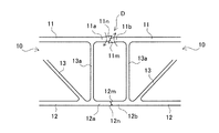
第1及び第2面板11,12の間に設けられた複数のリブ13は、隣り合うもの同士が交互に傾きを変えるように傾斜して配置されたものであるが、幅方向両端の端部リブ13aは、第1及び第2面板11,12に対して直交するように配置されている。そして、第1面板11及び第2面板12は、その端部リブ13aから幅方向に突き出し、自由端の接合部11a,11b及び12a,12bが形成されている。ここで、接合部11a,12aは、ダブルスキンパネル10の幅方向右側端部に形成されたものであり、接合部11b,12bは、同じダブルスキンパネル10の幅方向左側端部に形成されたものである。従って、ダブルスキンパネル10の左右両端部には互いが接合可能な継手になっており、これにより幅方向に並べられたダブルスキンパネル10同士が接合できるようになっている。
The plurality of
接合部11a,11b,12a,12bは、図5に示すように、ボビンツール150の回転体が入り込むスペースができるようにした端部リブ13aからの突出量である。そして、先端の接合端面は傾斜した傾斜面になっている。すなわち、ダブルスキンパネル10の右側端部にある接合部11a,12aの接合端面11m,12mは、互いが向き合う内側に傾斜し、左側端部にある接合部11b,12bの接合端面11n,12nは、互いが反対を向いた外側に傾斜して形成されている。従って、ダブルスキンパネル10は、接合端面11m,12mへ接合端面11n,12nが入り込んで嵌合するようになっている。
As shown in FIG. 5, the
本実施形態の製造方法は、こうした鉄道車両用構体を構成するダブルスキンパネル10同士を摩擦攪拌接合によって連結する方法である。ダブルスキンパネル10は、鉄道車両用構体を構成する隣り合うもの同士が図2に示すように架台1上に設置され、一方の端部に位置決ブロック3を当て、他方の端部からは押圧治具2によって荷重を加えた固定が行われる。接合するダブルスキンパネル10は、こうした位置決ブロック3と押圧治具2による固定が20メートルほどの全長にわたって数カ所で行われる。
The manufacturing method of this embodiment is a method of connecting the
このとき、一対のダブルスキンパネル10は、第1面板11の接合部11a,11bと第2面板12の接合部12a,12bとが、接合端面11m,11n同士と接合端面12m,12n同士が突き合わされている。しかし、全ての場合に接合端面同士が綺麗に突き合わされるとは限らず、例えば、図3に示すように、ダブルスキンパネル10の製作誤差によって、第2面板12の接合部12a,12bにおいて、その接合端面12m,12nの間に隙間Pが生じてしまうことがある。そうした場合、背景技術の欄で挙げた第3従来例では隙間を許容する方法がとられていたが、本実施形態では、その隙間Pを無くした状態にまでダブルスキンパネル10同士を押圧治具2によって押さえ付ける方法をとっている。
At this time, in the pair of
そのため、隙間Pを詰めて無くすように、ダブルスキンパネル10が所定の荷重で押圧される。こうした隙間Pは、第1面板11及び第2面板12の両方について、しかもダブルスキンパネル10の全長にわたって無くなるように各押圧治具2による押圧力の調整が行われる。ところで、第1面板11及び第2面板12の両方について、それぞれ隙間を無くすように押さえ付けが行われると、例えば図4に示すように、既に当接している反対側の接合部11a,11bには、その接合端面11m,11nが互いの傾斜面を滑って乗り上げ、矢印で示すように板厚方向(図面上下方向)に変形が生じる。ただし、図3に示す隙間Pや図4に示す接合部11a,11bの変形は、その状態が分かりやすいように誇張して表現したものであって、実際はこれほどの隙間間隔や変形量ではなく、極めて微小である。
Therefore, the
ダブルスキンパネル10は、20メートルほどの長さを有するため、比較的剛性の低い接合部11a,11b,12a,12bは、長手方向に見た場合に、僅かではあるが板厚方向に歪みが生じていることがある。そのため、接合箇所によっては、接合部11a,11b同士、接合部12a,12b同士で高さが異なることがあるが、本実施形態では前述した押さえ込みによって解消している。すなわち、一方のダブルスキンパネル10の接合端面11n,12nが、他方のダブルスキンパネル10の接合端面11m,12mの内側に入り込む。そのため、こうした接合端面同士の噛み合いの際、幅方向に作用する押圧力が、傾斜した接合端面11m,11n等を介し、接合部11a,11b等に板厚方向の分力となって作用する。
Since the
接合部11a,11b,12a,12bは、そもそも第1面板11や第2面板12の延長上に形成されているため、長手方向に見た場合に波打つように生じる歪みを修正させれれば、接合端面11m,11nなどの位置も第1面板11や第2面板12の高さに揃うことになる。よって、本実施形態では、ダブルスキンパネル10同士の接合部を幅方向に押圧して突き合わせる。そして、単純に接合端面同士を突き合わせるのではなく、一つは、隙間Pが生じている場合にその隙間Pを無くすことを目的とし、もう一つは、接合端面の斜面による板厚方向の分力によって同方向の歪みを修正することを目的としている。従って、押圧力は、当該二つの目的を達成できる大きさとする。
Since the
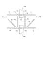
こうした押圧治具2によるダブルスキンパネル10の固定が行われた後は、ボビンツール150による摩擦攪拌接合が実行される。図5には、第1面板11と第2面板12を同時に行うように表現されているが、実際には図2に示すようにダブルスキンパネル10が固定され、そのダブルスキンパネル10に対して第1面板11側の接合が行われ、その後反転して上に位置した第2面板12側の接合が行われる。なお、ダブルスキンパネル10の固定の仕方によっては、図5に示すように第1面板11と第2面板12とを同時に行うようにしても良い。
After the
摩擦攪拌接合を行うためのボビンツール150は、第1回転体151と第2回転体152、及びその間に位置する攪拌軸153を備え、モータの駆動によって回転体151,152及び攪拌軸153に回転が与えられるように構成されたものである。第1回転体151と第2回転体152とは、その間隔が調整できるようになっており、所定の荷重をかけて接合部11a,11bなどを挟み込むことができるようになっている。
The
そこで、ボビンツール150は、図5で示すように、その攪拌軸153が接合端面11m,11nの当接位置(接合部分)に重なるように配置し、第1及び第2回転体151,152によって接合部11a,11bを挟み込む。そして、ボビンツール150は、回転しながら図2に示す接合線Sに沿って移動することで、攪拌軸153が接合端面11m,11nの当接部分を摩擦攪拌させ、その周囲の材料を塑性流動化させる。その際、接合部11a,11bを押さえ込んだ第1及び第2回転体151,152が可塑性ゾーンから材料が失われるのを防いでいる。軟化した材料は塑性流動化して攪拌混練され、攪拌軸153の後方に流れ、その後方で互いに混じり合った可塑性材が摩擦熱を失って急速に冷却固化して接合が完結する。
Therefore, as shown in FIG. 5, the
ところで、ダブルスキンパネル10同士を隙間無く幅方向に押さえ付けるため、図4の第1面板11側に見られるように、接合部11a,11bが互いに矢印で示す方向に乗り上げて変形し、段差部分Dを生じさせてしまうことがある。しかし、そうした段差部分Dの板厚方向の突き出し量は僅かである。そして、摩擦攪拌時には、接合部11a,11bなどを挟み込む第1及び第2回転体151,152は、段差部分Dの変形を戻す大きさの荷重をかけて上下方向から押さえ込んでいる。そのため、接合線Sに沿ってボビンツール150が摩擦攪拌を行う途中、段差部分Dでは、第1及び第2回転体151,152による押さえ込みによって変形が戻されるとともに、摩擦攪拌によって他の部分と攪拌混練されて流れる。そして、接合部11a,11bはそもそも同じ高さにあるため、ボビンツール150が通過した後の接合部に段差が生じることはなく、また余分な材料によるバリなどもほとんどできない。
By the way, in order to hold down the
第1面板11側の摩擦攪拌接合が完了した後は、そのダブルスキンパネル10が上下反転され、架台1の上に第2面板12側を上にして固定される。そして、ボビンツール150が一対の第1及び第2回転体151,152によって接合部12a,12bを挟み込み、回転しながら接合線Sに沿って移動することで、攪拌軸153が接合端面12m,12nの当接部分を摩擦攪拌して接合させる。そして、この第2面板12側においても、接合部11a,11bが互いに乗り上げていている段差部分Dが存在していても、その段差部分Dを第1及び第2回転体151,152で押さえ込むことにより、当該部分の変形を戻しながら摩擦攪拌接合が行われる。
After the friction stir welding on the
本実施形態の摩擦攪拌接合による鉄道車両用構体の製造方法では、ダブルスキンパネル10同士を押圧治具2によって幅方向に所定の荷重で押し付けることにより、隙間Pを無くすとともに、接合端面同士の接合部分に生じている板厚方向の歪みを修正する。従って、材料が隙間Pに流れ込んで接合後に凹みなどを生じさせることなく、仕上がりの良い接合面とすることができる。また、従来は板厚方向の歪みによって生じる段差箇所を探し出し、ハンマーでたたいて修正するという作業が必要であったが、本実施形態によれば、そうした煩わしい作業を省くことが可能になる。
更に、本実施形態によれば、一の面板側の隙間Pをなくすようにダブルスキンパネル10を押し付けると、他の面板側の接合部分に傾斜面を乗り上げた段差部分Dを生じるが、それをボビンツール150で押さえ込むことにより、変形を戻して仕上げの良い接合を行うことが可能である。
In the method for manufacturing a railway vehicle structure by friction stir welding according to the present embodiment, the
Furthermore, according to the present embodiment, when the
以上、本発明に係る摩擦攪拌接合による鉄道車両用構体の製造方法について一実施形態を説明したが、本発明はこれに限定されることなく、その趣旨を逸脱しない範囲で様々な変更が可能である。
前記実施形態では第1及び第2面板11,12が平面のダブルスキンパネル10を例に挙げて説明したが、ダブルスキンパネル10は、例えば屋根構体を構成する湾曲したもの同士、或いは湾曲したものと平面のものとの接合でもよい。
As mentioned above, although one embodiment was described about the manufacturing method of the structure for rail vehicles by the friction stir welding concerning the present invention, the present invention is not limited to this, but various changes are possible in the range which does not deviate from the meaning. is there.
In the above-described embodiment, the first and
1 架台
2 押圧治具
3 位置決ブロック
10 ダブルスキンパネル
11 第1面板
12 第2面板
13 リブ
11a,11b,12a,12b 接合部
11m,11n,12m,12n 接合端面
13a 端部リブ
150 ボビンツール
151 第1回転体
152 第2回転体
153 攪拌軸
P 隙間
DESCRIPTION OF SYMBOLS 1 Base 2 Pressing jig 3
本発明に係る摩擦攪拌接合による鉄道車両用構体の製造方法は、鉄道車両用構体を構成する所定幅の長尺な一対の第1面板と第2面板とを幅方向に並んだ複数のリブによって連結したダブルスキンパネルが、幅方向端部にあって前記第1及び第2面板とほぼ直交する端部リブから前記第1及び第2面板が延長して突き出した接合部を有し、その接合部の接合端面には、同じ幅方向端部において前記第1及び第2面板とで異なる方向に傾斜した接合端面が形成されたものであって、幅方向に並べた2枚の前記ダブルスキンパネルについて、同方向に傾斜した接合端面同士を突き合わせ、両ダブルスキンパネルの接合部を、ボビンツール型をした摩擦攪拌接合用工具の一対の回転体によって挟み込み、その回転体の間の攪拌軸によって前記接合端面同士を突き合わせた接合部分を長手方向に沿って摩擦攪拌して接合するものであり、前記第1面板同士及び第2面板同士の前記接合部分について、前記ダブルスキンパネルの全長にわたって前記第1面板側及び第2面板側の両方に隙間が生じないようにするため、前記第1面板側及び第2面板側の一方の接合部分に隙間がある場合には、当該一方の接合部分の隙間を無くし、他方の接合部分では前記接合端面同士を滑らせた接合部が面板の板厚方向に変形を生じるように、前記ダブルスキンパネルを幅方向に荷重をかけた状態で固定し、その接合部分を摩擦攪拌接合用工具の一対の回転体によって挟んで押さえ込み、長手方向に沿って回転移動する攪拌軸によって摩擦攪拌して接合することを特徴とする。
また、本発明に係る摩擦攪拌接合による鉄道車両用構体の製造方法は、前記摩擦攪拌接合用工具の一対の回転体による接合部の押さえ込みは、前記ダブルスキンパネルに対する幅方向の荷重によって生じる前記接合端面の滑りによる接合部の変形を戻す大きさの荷重で行うことが好ましい。
A method for manufacturing a railway vehicle structure by friction stir welding according to the present invention includes a plurality of ribs in which a pair of long first face plates and second face plates having a predetermined width constituting the railway vehicle structure are arranged in the width direction. The connected double skin panel has a joint portion at the end portion in the width direction, in which the first and second face plates extend and protrude from end ribs that are substantially orthogonal to the first and second face plates. Two double skin panels arranged in the width direction are formed on the joint end face of the portion, and are formed with joint end faces inclined in different directions from the first and second face plates at the same width direction end. The joint end surfaces inclined in the same direction are butted together, and the joint portion of both double skin panels is sandwiched by a pair of rotating bodies of a friction stir welding tool having a bobbin tool type, and the stirring shaft between the rotating bodies Junction end The joined portions that are brought into contact with each other are frictionally agitated and joined along the longitudinal direction, and the joined portions of the first face plates and the second face plates are joined to the first face plate side over the entire length of the double skin panel. In order to prevent a gap on both the second face plate side and the first face plate side and the second face plate side, if there is a gap on the one face portion, the gap on the one face portion is eliminated. In the other joint part, the double skin panel is fixed in a state where a load is applied in the width direction so that the joint part slid between the joint end faces is deformed in the thickness direction of the face plate , and the joint part is rubbed. It is characterized in that it is sandwiched and pressed by a pair of rotating bodies of a stir welding tool, and friction stir by a stirring shaft that rotates and moves along the longitudinal direction.
Further, in the method of manufacturing a railway vehicle structure by friction stir welding according to the present invention, the pressing of the joint portion by the pair of rotating bodies of the friction stir welding tool is caused by the load in the width direction on the double skin panel. It is preferable to carry out with the load of the magnitude | size which returns the deformation | transformation of a junction part by the slip of an end surface.
接合部11a,11b,12a,12bは、そもそも第1面板11や第2面板12の延長上に形成されているため、長手方向に見た場合に波打つように生じる歪みを修正すれば、接合端面11m,11nなどの位置も第1面板11や第2面板12の高さに揃うことになる。よって、本実施形態では、ダブルスキンパネル10同士の接合部を幅方向に押圧して突き合わせる。そして、単純に接合端面同士を突き合わせるのではなく、一つは、隙間Pが生じている場合にその隙間Pを無くすことを目的とし、もう一つは、接合端面の斜面による板厚方向の分力によって同方向の歪みを修正することを目的としている。従って、押圧力は、当該二つの目的を達成できる大きさとする。
Since the
第1面板11側の摩擦攪拌接合が完了した後は、そのダブルスキンパネル10が上下反転され、架台1の上に第2面板12側を上にして固定される。そして、ボビンツール150が一対の第1及び第2回転体151,152によって接合部12a,12bを挟み込み、回転しながら接合線Sに沿って移動することで、攪拌軸153が接合端面12m,12nの当接部分を摩擦攪拌して接合させる。そして、この第2面板12側においても、接合部12a,12bが互いに乗り上げていている段差部分Dが存在していても、その段差部分Dを第1及び第2回転体151,152で押さえ込むことにより、当該部分の変形を戻しながら摩擦攪拌接合が行われる。
After the friction stir welding on the
本発明に係る摩擦攪拌接合による鉄道車両用構体の製造方法は、鉄道車両用構体を構成する所定幅の長尺な一対の第1面板と第2面板とを幅方向に並んだ複数のリブによって連結したダブルスキンパネルが、幅方向端部にあって前記第1及び第2面板とほぼ直交する端部リブから前記第1及び第2面板が延長して突き出した接合部を有し、その接合部の接合端面には、同じ幅方向端部において前記第1及び第2面板とで異なる方向に傾斜した接合端面が形成されたものであって、幅方向に並べた2枚の前記ダブルスキンパネルについて、同方向に傾斜した接合端面同士を突き合わせ、両ダブルスキンパネルの接合部を、ボビンツール型をした摩擦攪拌接合用工具の一対の回転体によって挟み込み、その回転体の間の攪拌軸によって前記接合端面同士を突き合わせた接合部分を長手方向に沿って摩擦攪拌して接合するものであり、前記第1面板同士及び第2面板同士の前記接合部分について、前記ダブルスキンパネルの全長にわたって前記第1面板側及び第2面板側の両方に隙間が生じないようにするため、前記第1面板側及び第2面板側の一方の接合部分に隙間がある場合には、当該一方の接合部分の隙間を無くし、他方の接合部分では前記接合端面同士を滑らせた接合部が面板の板厚方向に変形を生じるように、前記ダブルスキンパネルを幅方向に荷重をかけた状態で固定し、その接合部分を摩擦攪拌接合用工具の一対の回転体によって挟んで押さえ込み、長手方向に沿って回転移動する攪拌軸によって摩擦攪拌して接合する際、前記板厚方向の変形が生じた方の接合部分では、前記摩擦攪拌接合用工具の一対の回転体が、その変形を戻す大きさの荷重で押さえ込むようにしたことを特徴とする。
A method for manufacturing a railway vehicle structure by friction stir welding according to the present invention includes a plurality of ribs in which a pair of long first face plates and second face plates having a predetermined width constituting the railway vehicle structure are arranged in the width direction. The connected double skin panel has a joint portion at the end portion in the width direction, in which the first and second face plates extend and protrude from end ribs that are substantially orthogonal to the first and second face plates. Two double skin panels arranged in the width direction are formed on the joint end face of the portion, and are formed with joint end faces inclined in different directions from the first and second face plates at the same width direction end. The joint end surfaces inclined in the same direction are butted together, and the joint portion of both double skin panels is sandwiched by a pair of rotating bodies of a friction stir welding tool having a bobbin tool type, and the stirring shaft between the rotating bodies Junction end The joined portions that are brought into contact with each other are frictionally agitated and joined along the longitudinal direction, and the joined portions of the first face plates and the second face plates are joined to the first face plate side over the entire length of the double skin panel. In order to prevent a gap on both the second face plate side and the first face plate side and the second face plate side, if there is a gap on the one face portion, the gap on the one face portion is eliminated. In the other joint part, the double skin panel is fixed in a state where a load is applied in the width direction so that the joint part slid between the joint end faces is deformed in the thickness direction of the face plate, and the joint part is rubbed. holding down across the pair of rotating bodies of stir welding tool, when joined with stirring by friction stir shaft rotated moves along the longitudinal direction, the joint portion towards the deformation of the plate thickness direction is generated, A pair of rotating bodies of serial friction stir welding tool, characterized in that as press down with a load of magnitude return the deformation.
Claims (2)
幅方向に並べた2枚の前記ダブルスキンパネルについて、同方向に傾斜した接合端面同士を突き合わせ、両ダブルスキンパネルの接合部を、ボビンツール型をした摩擦攪拌接合用工具の一対の回転体によって挟み込み、その回転体の間の攪拌軸によって前記接合端面同士を突き合わせた接合部分を長手方向に沿って摩擦攪拌して接合する、摩擦攪拌接合による鉄道車両用構体の製造方法において、
前記第1面板同士及び第2面板同士の前記接合部分について、前記ダブルスキンパネルの全長にわたって前記第1面板側及び第2面板側の両方に隙間が生じないように、前記ダブルスキンパネルを幅方向に荷重をかけた状態で固定し、
その接合部分を摩擦攪拌接合用工具の一対の回転体によって挟んで押さえ込み、長手方向に沿って回転移動する攪拌軸によって摩擦攪拌して接合することを特徴とする摩擦攪拌接合による鉄道車両用構体の製造方法。 A double skin panel in which a pair of long first face plates having a predetermined width and a second face plate constituting a railway vehicle structure are connected by a plurality of ribs arranged in the width direction is disposed at an end in the width direction and the first And the first and second face plates extend and project from end ribs substantially orthogonal to the second face plate, and the joint end faces of the joint portions have the first and second ends at the same widthwise end. A joining end face inclined in a different direction from the second face plate is formed,
For the two double skin panels arranged in the width direction, the joint end surfaces inclined in the same direction are brought into contact with each other, and the joint portions of both double skin panels are formed by a pair of rotating bodies of a friction stir welding tool having a bobbin tool type. In the manufacturing method of a railway vehicle structure by friction stir welding, the joint portion where the joint end surfaces are butted together by the stirring shaft between the rotating bodies is frictionally stirred along the longitudinal direction.
About the joint portion between the first face plates and the second face plates, the double skin panel is arranged in the width direction so that no gap is generated on both the first face plate side and the second face plate side over the entire length of the double skin panel. Fixed with a load on
A structure of a railway vehicle body by friction stir welding, characterized in that the joint portion is sandwiched and pressed by a pair of rotating bodies of a friction stir welding tool, and friction stir is joined by a stirring shaft that rotates and moves along the longitudinal direction. Production method.
前記摩擦攪拌接合用工具の一対の回転体による接合部の押さえ込みは、前記ダブルスキンパネルに対する幅方向の荷重によって生じる前記接合端面の滑りによる接合部の変形を戻す大きさの荷重で行うことを特徴とする摩擦攪拌接合による鉄道車両用構体の製造方法。 In the manufacturing method of the structure for rail vehicles by the friction stir welding of Claim 1,
The pressing of the bonded portion by the pair of rotating bodies of the friction stir welding tool is performed with a load having a magnitude that returns deformation of the bonded portion due to slippage of the bonded end surface caused by a load in the width direction with respect to the double skin panel. A method for manufacturing a railway vehicle structure by friction stir welding.
Priority Applications (1)
| Application Number | Priority Date | Filing Date | Title |
|---|---|---|---|
| JP2008233421A JP4298784B1 (en) | 2008-09-11 | 2008-09-11 | Method for manufacturing railway vehicle structure by friction stir welding |
Applications Claiming Priority (1)
| Application Number | Priority Date | Filing Date | Title |
|---|---|---|---|
| JP2008233421A JP4298784B1 (en) | 2008-09-11 | 2008-09-11 | Method for manufacturing railway vehicle structure by friction stir welding |
Publications (2)
| Publication Number | Publication Date |
|---|---|
| JP4298784B1 JP4298784B1 (en) | 2009-07-22 |
| JP2010064634A true JP2010064634A (en) | 2010-03-25 |
Family
ID=40972369
Family Applications (1)
| Application Number | Title | Priority Date | Filing Date |
|---|---|---|---|
| JP2008233421A Expired - Fee Related JP4298784B1 (en) | 2008-09-11 | 2008-09-11 | Method for manufacturing railway vehicle structure by friction stir welding |
Country Status (1)
| Country | Link |
|---|---|
| JP (1) | JP4298784B1 (en) |
Cited By (4)
| Publication number | Priority date | Publication date | Assignee | Title |
|---|---|---|---|---|
| WO2014109592A1 (en) * | 2013-01-11 | 2014-07-17 | 주식회사 우신이엠시 | Hybrid drive shaft using friction-stir welding and fabrication method thereof |
| JP2016068898A (en) * | 2014-10-01 | 2016-05-09 | 日本車輌製造株式会社 | Aluminum side structure manufacturing method |
| JP2020006852A (en) * | 2018-07-10 | 2020-01-16 | 日本車輌製造株式会社 | Railway vehicle |
| CN110773896A (en) * | 2019-11-12 | 2020-02-11 | 河北京车轨道交通车辆装备有限公司 | Method for controlling deformation of 100% low-floor modern tramcar aluminum alloy body |
Families Citing this family (3)
| Publication number | Priority date | Publication date | Assignee | Title |
|---|---|---|---|---|
| US9166130B2 (en) | 2012-10-24 | 2015-10-20 | Spectrasensors, Inc. | Solderless mounting for semiconductor lasers |
| US9166364B2 (en) | 2011-02-14 | 2015-10-20 | Spectrasensors, Inc. | Semiconductor laser mounting with intact diffusion barrier layer |
| US9368934B2 (en) | 2011-02-14 | 2016-06-14 | Spectrasensors, Inc. | Semiconductor laser mounting for improved frequency stability |
Citations (14)
| Publication number | Priority date | Publication date | Assignee | Title |
|---|---|---|---|---|
| JPH1052773A (en) * | 1996-08-06 | 1998-02-24 | Hitachi Ltd | Manufacture of structure for railway vehicle and its device |
| JPH10193139A (en) * | 1997-01-17 | 1998-07-28 | Showa Alum Corp | Friction stirring welding method |
| JPH1158036A (en) * | 1997-08-07 | 1999-03-02 | Hitachi Ltd | Friction welding method and weld joint structure |
| JPH11320127A (en) * | 1998-05-07 | 1999-11-24 | Showa Alum Corp | Method and device for friction agitation joining |
| JP2001205453A (en) * | 2000-01-25 | 2001-07-31 | Kawasaki Heavy Ind Ltd | Jig for friction stir joining |
| JP2003326376A (en) * | 2002-05-09 | 2003-11-18 | Mitsubishi Heavy Ind Ltd | Friction-stirring joined body and its manufacturing method |
| JP2004042115A (en) * | 2002-07-12 | 2004-02-12 | Mitsubishi Heavy Ind Ltd | Double skin panel and friction stir welding method for the double skin panel |
| JP2004243334A (en) * | 2003-02-12 | 2004-09-02 | Nippon Light Metal Co Ltd | Double skin panel, and friction stir joining method therefor |
| JP2004243379A (en) * | 2003-02-14 | 2004-09-02 | Mitsubishi Heavy Ind Ltd | Hollow structure shaped material and method for manufacturing structure |
| JP2005028421A (en) * | 2003-07-09 | 2005-02-03 | Showa Denko Kk | Butt joint manufacturing method, butt joint and friction stir welding equipment |
| JP2005193254A (en) * | 2004-01-05 | 2005-07-21 | Hitachi Industries Co Ltd | Friction stir joining method |
| JP2007283379A (en) * | 2006-04-19 | 2007-11-01 | Nippon Sharyo Seizo Kaisha Ltd | Joined member, joining body, and friction stirring and joining method |
| JP2007326117A (en) * | 2006-06-07 | 2007-12-20 | Nippon Sharyo Seizo Kaisha Ltd | Double skin panel and its bonded joint, and structural body |
| JP2008012550A (en) * | 2006-07-04 | 2008-01-24 | Nippon Sharyo Seizo Kaisha Ltd | Double skin panel, its joint structure, and structural body |
-
2008
- 2008-09-11 JP JP2008233421A patent/JP4298784B1/en not_active Expired - Fee Related
Patent Citations (14)
| Publication number | Priority date | Publication date | Assignee | Title |
|---|---|---|---|---|
| JPH1052773A (en) * | 1996-08-06 | 1998-02-24 | Hitachi Ltd | Manufacture of structure for railway vehicle and its device |
| JPH10193139A (en) * | 1997-01-17 | 1998-07-28 | Showa Alum Corp | Friction stirring welding method |
| JPH1158036A (en) * | 1997-08-07 | 1999-03-02 | Hitachi Ltd | Friction welding method and weld joint structure |
| JPH11320127A (en) * | 1998-05-07 | 1999-11-24 | Showa Alum Corp | Method and device for friction agitation joining |
| JP2001205453A (en) * | 2000-01-25 | 2001-07-31 | Kawasaki Heavy Ind Ltd | Jig for friction stir joining |
| JP2003326376A (en) * | 2002-05-09 | 2003-11-18 | Mitsubishi Heavy Ind Ltd | Friction-stirring joined body and its manufacturing method |
| JP2004042115A (en) * | 2002-07-12 | 2004-02-12 | Mitsubishi Heavy Ind Ltd | Double skin panel and friction stir welding method for the double skin panel |
| JP2004243334A (en) * | 2003-02-12 | 2004-09-02 | Nippon Light Metal Co Ltd | Double skin panel, and friction stir joining method therefor |
| JP2004243379A (en) * | 2003-02-14 | 2004-09-02 | Mitsubishi Heavy Ind Ltd | Hollow structure shaped material and method for manufacturing structure |
| JP2005028421A (en) * | 2003-07-09 | 2005-02-03 | Showa Denko Kk | Butt joint manufacturing method, butt joint and friction stir welding equipment |
| JP2005193254A (en) * | 2004-01-05 | 2005-07-21 | Hitachi Industries Co Ltd | Friction stir joining method |
| JP2007283379A (en) * | 2006-04-19 | 2007-11-01 | Nippon Sharyo Seizo Kaisha Ltd | Joined member, joining body, and friction stirring and joining method |
| JP2007326117A (en) * | 2006-06-07 | 2007-12-20 | Nippon Sharyo Seizo Kaisha Ltd | Double skin panel and its bonded joint, and structural body |
| JP2008012550A (en) * | 2006-07-04 | 2008-01-24 | Nippon Sharyo Seizo Kaisha Ltd | Double skin panel, its joint structure, and structural body |
Cited By (7)
| Publication number | Priority date | Publication date | Assignee | Title |
|---|---|---|---|---|
| WO2014109592A1 (en) * | 2013-01-11 | 2014-07-17 | 주식회사 우신이엠시 | Hybrid drive shaft using friction-stir welding and fabrication method thereof |
| KR101422584B1 (en) | 2013-01-11 | 2014-07-24 | 주식회사 우신이엠시 | Friction stir welding method |
| US9958003B2 (en) | 2013-01-11 | 2018-05-01 | Woo Shin Emc Co., Ltd. | Hybrid drive shaft using friction-stir welding and fabrication method thereof |
| JP2016068898A (en) * | 2014-10-01 | 2016-05-09 | 日本車輌製造株式会社 | Aluminum side structure manufacturing method |
| JP2020006852A (en) * | 2018-07-10 | 2020-01-16 | 日本車輌製造株式会社 | Railway vehicle |
| JP7217575B2 (en) | 2018-07-10 | 2023-02-03 | 日本車輌製造株式会社 | Manufacturing method of railway vehicle and railway vehicle |
| CN110773896A (en) * | 2019-11-12 | 2020-02-11 | 河北京车轨道交通车辆装备有限公司 | Method for controlling deformation of 100% low-floor modern tramcar aluminum alloy body |
Also Published As
| Publication number | Publication date |
|---|---|
| JP4298784B1 (en) | 2009-07-22 |
Similar Documents
| Publication | Publication Date | Title |
|---|---|---|
| JP4298784B1 (en) | Method for manufacturing railway vehicle structure by friction stir welding | |
| JP3589930B2 (en) | Friction stir welding method | |
| KR100428544B1 (en) | Friction welding method, and manufacturing method of structure body and vehicles using friction welding method, and structure body and vehicles thereby | |
| JP3538357B2 (en) | Friction stir welding method | |
| JP4359291B2 (en) | Joined member | |
| JP3751215B2 (en) | Friction stir welding method | |
| JP4516976B2 (en) | Double skin panel joint | |
| JP2005239029A (en) | Railway vehicle structural body | |
| JP4336351B2 (en) | Structure | |
| JP4619999B2 (en) | Double skin panel and joint structure thereof, and structure | |
| JP2009190090A (en) | Bonding joint of hollow material and bonded body | |
| JP2004223587A (en) | Joint structure of hollow extruded shape | |
| JP4427273B2 (en) | Structure manufacturing method and apparatus | |
| JP2006224160A (en) | Extruded hollow shape material and railroad car structure formed therewith | |
| JP4610522B2 (en) | Double skin panel and its joint, and structure | |
| JP4620016B2 (en) | Friction stir welding joint and joined body | |
| JP2003326373A (en) | Joined body of plurality of linear members with friction- stirring and its manufacturing method | |
| JP4440522B2 (en) | Hollow profile for friction stir welding | |
| JP3459206B2 (en) | Hollow profile for friction stir welding | |
| JP3565756B2 (en) | Shaped material for friction stir welding | |
| JP4298451B2 (en) | Panel joint structure | |
| JP3442660B2 (en) | Joining panel structure and panel | |
| JP4402062B2 (en) | Friction stir welding method | |
| JP3179758B2 (en) | Friction joining method and structure | |
| JP4402061B2 (en) | Panel structure |
Legal Events
| Date | Code | Title | Description |
|---|---|---|---|
| TRDD | Decision of grant or rejection written | ||
| A01 | Written decision to grant a patent or to grant a registration (utility model) |
Free format text: JAPANESE INTERMEDIATE CODE: A01 Effective date: 20090407 |
|
| A01 | Written decision to grant a patent or to grant a registration (utility model) |
Free format text: JAPANESE INTERMEDIATE CODE: A01 |
|
| A61 | First payment of annual fees (during grant procedure) |
Free format text: JAPANESE INTERMEDIATE CODE: A61 Effective date: 20090415 |
|
| R150 | Certificate of patent or registration of utility model |
Ref document number: 4298784 Country of ref document: JP Free format text: JAPANESE INTERMEDIATE CODE: R150 Free format text: JAPANESE INTERMEDIATE CODE: R150 |
|
| FPAY | Renewal fee payment (event date is renewal date of database) |
Free format text: PAYMENT UNTIL: 20120424 Year of fee payment: 3 |
|
| FPAY | Renewal fee payment (event date is renewal date of database) |
Free format text: PAYMENT UNTIL: 20120424 Year of fee payment: 3 |
|
| FPAY | Renewal fee payment (event date is renewal date of database) |
Free format text: PAYMENT UNTIL: 20130424 Year of fee payment: 4 |
|
| R250 | Receipt of annual fees |
Free format text: JAPANESE INTERMEDIATE CODE: R250 |
|
| FPAY | Renewal fee payment (event date is renewal date of database) |
Free format text: PAYMENT UNTIL: 20140424 Year of fee payment: 5 |
|
| R250 | Receipt of annual fees |
Free format text: JAPANESE INTERMEDIATE CODE: R250 |
|
| R250 | Receipt of annual fees |
Free format text: JAPANESE INTERMEDIATE CODE: R250 |
|
| R250 | Receipt of annual fees |
Free format text: JAPANESE INTERMEDIATE CODE: R250 |
|
| R250 | Receipt of annual fees |
Free format text: JAPANESE INTERMEDIATE CODE: R250 |
|
| R250 | Receipt of annual fees |
Free format text: JAPANESE INTERMEDIATE CODE: R250 |
|
| R250 | Receipt of annual fees |
Free format text: JAPANESE INTERMEDIATE CODE: R250 |
|
| LAPS | Cancellation because of no payment of annual fees |