JP2010063555A - Pinball game machine - Google Patents

Pinball game machine Download PDF

Info

Publication number
JP2010063555A
JP2010063555A JP2008231568A JP2008231568A JP2010063555A JP 2010063555 A JP2010063555 A JP 2010063555A JP 2008231568 A JP2008231568 A JP 2008231568A JP 2008231568 A JP2008231568 A JP 2008231568A JP 2010063555 A JP2010063555 A JP 2010063555A
Authority
JP
Japan
Prior art keywords
operation unit
ball
hand
base
game
Prior art date
Legal status (The legal status is an assumption and is not a legal conclusion. Google has not performed a legal analysis and makes no representation as to the accuracy of the status listed.)
Granted
Application number
JP2008231568A
Other languages
Japanese (ja)
Other versions
JP5178416B2 (en
Inventor
Takaaki Ichihara
高明 市原
Yoshihiro Sato
義浩 佐藤
Current Assignee (The listed assignees may be inaccurate. Google has not performed a legal analysis and makes no representation or warranty as to the accuracy of the list.)
Daiichi Shokai Co Ltd
Original Assignee
Daiichi Shokai Co Ltd
Priority date (The priority date is an assumption and is not a legal conclusion. Google has not performed a legal analysis and makes no representation as to the accuracy of the date listed.)
Filing date
Publication date
Application filed by Daiichi Shokai Co Ltd filed Critical Daiichi Shokai Co Ltd
Priority to JP2008231568A priority Critical patent/JP5178416B2/en
Publication of JP2010063555A publication Critical patent/JP2010063555A/en
Application granted granted Critical
Publication of JP5178416B2 publication Critical patent/JP5178416B2/en
Expired - Fee Related legal-status Critical Current
Anticipated expiration legal-status Critical

Links

Images

Abstract

<P>PROBLEM TO BE SOLVED: To provide a pinball game machine capable of lightly returning to a state before game start when a player releases a hand from the state during a game of operating a hitting force adjusting device. <P>SOLUTION: In the pinball game machine including a ball hitting member for hitting a game ball and the hitting force adjusting device for adjusting the hitting force of the ball hitting member, the hitting force adjusting device includes an operation base projecting roughly horizontally from a lower part on the front side of the machine, an operation part 16 having a bottom part 16a and a hand mounting part 16b and capable of swing turning centering on a fixed point, an adjusting means for adjusting the ball hitting member by the swing turning of the operation part 16, an operation part returning means for urging the operation part 16 toward an initial position, and an operation part floating urging means 20 for floating the bottom part 16a of the operation part 16 from the operation base and forming a gap. The operation part 16 and the operation base are brought into contact by the tare of the operation part 16 and the weight of a hand, and a gap is formed between the operation part 16 and the operation base by the action of the operation part floating urging means 20 in the state of releasing the hand from the operation part 16. <P>COPYRIGHT: (C)2010,JPO&INPIT

Description

本発明は、遊技板の遊技領域に遊技球を発射させて遊技を行う弾球遊技機に関する。   The present invention relates to a ball game machine that performs a game by firing a game ball on a game area of a game board.

弾球遊技機の一例をパチンコ機について説明する。
周知のようにパチンコ機は、遊技者が遊技板の遊技領域に向けて遊技球(一般に「パチンコ球」という。)を発射させ、その遊技球が遊技領域の入賞口に入った場合に景品として複数個の遊技球を機前の球皿に放出し、一方、遊技球が入賞しなかった場合にその遊技球をアウト球として機裏に排出するものである。
An example of a ball game machine will be described for a pachinko machine.
As is well known, a pachinko machine is used as a prize when a player launches a game ball (generally referred to as a “pachinko ball”) toward the game area of the game board, and the game ball enters the winning area of the game area. A plurality of game balls are discharged to a ball tray in front of the machine. On the other hand, when a game ball is not won, the game ball is discharged as an out ball to the back of the machine.

パチンコ機には、遊技板の遊技領域に向けて遊技球を発射させる球発射部材と、該球発射部材の発射力の強弱を調節する発射力調節装置とが設けられている。前記球発射部材は、主として発射レール上に供給した遊技球を一個ずつ打ち出す電動打球槌で構成されており、発射力調節装置は、その電動打球槌の発射力、すなわち電動打球槌の打撃力の強弱を調節する。   The pachinko machine is provided with a ball launching member that launches a game ball toward the game area of the game board, and a firing force adjusting device that adjusts the strength of the launching force of the ball launching member. The ball launching member is mainly composed of an electric ball striking ball that launches game balls supplied one by one on the firing rail, and the firing force adjusting device has a firing force of the electric ball striking force, that is, an impact force of the electric ball striking force. Adjust strength.

前記発射力調節装置は、図13に示したように機前の下方から遊技者側に向けてほぼ水平に突設したハンドルアーム101と、該ハンドルアーム101の先端に垂直方向に立ち上げた円形のハンドルグリップ102と、このハンドルグリップ102の周面に設けた打球発射調整操作用のダイヤル103と、を備え、前記ハンドルグリップ102の内部に設けた可変抵抗器の電気抵抗値を前記ダイヤル103によって適宜変更し、そうして電動打球槌に印加する電圧値を変更して打撃力の強弱を調節する。   As shown in FIG. 13, the firing force adjusting device includes a handle arm 101 projecting substantially horizontally from the lower front of the machine toward the player side, and a circular shape rising vertically at the tip of the handle arm 101. The handle grip 102 and a dial 103 for adjusting the hitting ball launching operation provided on the peripheral surface of the handle grip 102, and the electric resistance value of the variable resistor provided inside the handle grip 102 is determined by the dial 103. Change the voltage appropriately, and then change the voltage value applied to the electric ball to adjust the strength of the hitting force.

特開平11−128488号公報(段落0037)JP 11-128488 A (paragraph 0037)

一般に弾球遊技機の発射力調節装置は、遊技者が手で操作している遊技時の状態から手を離したとき、遊技開始前の状態に戻るようになっている。   In general, when a player releases his / her hand from the game state that the player is operating with his / her hand, the firing force adjusting device of the ball ball game machine returns to the state before starting the game.

本発明の目的は、遊技者が発射力調節装置を手で操作している遊技時の状態から遊技者が手を離したとき、遊技開始前の状態に軽やかに戻り得るようにした弾球遊技機を提供することにある。   An object of the present invention is to provide a ball game in which when a player releases his / her hand from a state in which the player operates the firing force adjusting device by hand, the player can easily return to the state before starting the game. Is to provide a machine.

遊技板の遊技領域に向けて遊技球を発射させる球発射部材と、該球発射部材の発射力の強弱を調節する発射力調節装置と、を有する弾球遊技機において、
前記発射力調節装置は、
機前の下方から遊技者側に向けてほぼ水平に突設した操作基台と、
該操作基台の上面に対向する底部とその底部上にあって遊技者が手の平を載せ置くための手載せ部とを有し、定点を中心としたほぼ扇形の軌跡を描く状態で首振り回動可能な操作部と、
該操作部の首振り回動によって前記球発射部材の発射力を強弱させ得る調節手段と、
前記操作部を前記球発射部材の発射動作が停止するよう関連付けられた初期位置に向けて付勢する操作部復動手段と、
前記操作部の底部を前記操作基台の上面から浮かせて底部との間に隙間を形成することが可能な操作部浮揚付勢手段と、を備え、
遊技者が前記操作部に手を載せ置いた遊技時の状態では操作部の自重と遊技者の手の重量によって操作部の底部と操作基台の上面とが接触し、遊技者が操作部から手を離した状態では操作部浮揚付勢手段の作用により操作部の底部と操作基台の上面との間に隙間が形成され、その状態で前記操作部復動手段により操作部が前記初期位置に復動するようになっている弾球遊技機を提供する。
In a ball game machine having a ball launching member that launches a game ball toward the game area of the game board, and a firing force adjusting device that adjusts the strength of the firing force of the ball launching member,
The firing force adjusting device includes:
An operation base that protrudes almost horizontally from the lower front of the machine toward the player,
The operation base has a bottom facing the top surface and a hand rest on the bottom for placing a palm on the player, and swings in a substantially fan-shaped locus centered on a fixed point. A movable operation unit,
Adjusting means capable of increasing or decreasing the firing force of the ball launching member by swinging the operation part;
An operation unit return means for urging the operation unit toward an associated initial position so that the firing operation of the ball projecting member stops;
An operation unit levitation biasing means capable of floating the bottom of the operation unit from the upper surface of the operation base and forming a gap with the bottom, and
When the player places his / her hand on the operation unit, the bottom of the operation unit and the upper surface of the operation base come into contact with each other due to the weight of the operation unit and the weight of the player's hand. When the hand is released, a gap is formed between the bottom of the operation unit and the upper surface of the operation base by the action of the operation unit levitation biasing means, and in this state, the operation unit is moved to the initial position by the operation unit return means. To provide a ball game machine that is adapted to return to

本発明の弾球遊技機の発射力調節装置は、操作部が操作部浮揚付勢手段で支えられている状態では、操作部の底部と操作基台の上面との間に隙間ができるから、操作部復動手段による操作部の復動が軽やかに行える効果がある。
一方、操作部浮揚付勢手段は、操作部の手載せ部に遊技者が手を載せた場合に、その手の重量の増加分に抗しきれずに操作部が下がってその底部と操作基台の上面とを接触させるから、操作部復動手段の付勢に抗して操作部を任意の位置に停止させておくことが容易になる。
In the state in which the operation unit is supported by the operation unit levitation biasing means, a gap is formed between the bottom of the operation unit and the upper surface of the operation base in the state where the operation unit is supported by the operation unit levitation biasing means. There is an effect that the operation part can be moved backward easily by the operation part return means.
On the other hand, when the player places his / her hand on the hand-held part of the operating part, the operating part floats and the operating part lowers without resisting the increase in the weight of the hand, and the bottom part and the operating base. Therefore, it is easy to stop the operation unit at an arbitrary position against the bias of the operation unit return means.

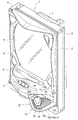
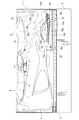
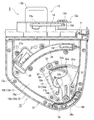
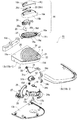
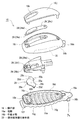
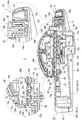
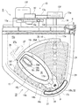
以下に本発明の実施の形態を弾球遊技機の一例たるパチンコ機を例に図面を参照しつつ説明する。なお、図1はパチンコ機の斜視図、図2はパチンコ機の要部を示す部分正面図、図3は発射力調節装置と球発射部材を示すためのパチンコ機の要部水平断面図、図4は操作基台の高さの中間を横断するパチンコ機の要部水平断面図、図5は図4の状態から操作部を回動させた状態を示すパチンコ機の要部水平断面図、図6(a),(b)は操作部浮揚付勢手段を説明するためのもので操作部と操作基台の要部を示す縦断面図、図7は発射力調節装置の分解斜視図、図8は操作部の分解斜視図、図9は操作基台内部の部品を示す分解斜視図、図10は図3のA−A線断面図、図11,図12は他の形態を示すパチンコ機の要部水平断面図である。   Embodiments of the present invention will be described below with reference to the drawings, taking a pachinko machine as an example of a ball game machine as an example. 1 is a perspective view of the pachinko machine, FIG. 2 is a partial front view showing the main part of the pachinko machine, and FIG. 3 is a horizontal cross-sectional view of the main part of the pachinko machine for showing the launch force adjusting device and the ball launching member. 4 is a horizontal cross-sectional view of the main part of the pachinko machine crossing the middle of the height of the operation base, FIG. 5 is a horizontal cross-sectional view of the main part of the pachinko machine showing the state in which the operation part is rotated from the state of FIG. 6 (a) and 6 (b) are longitudinal sectional views showing the main part of the operating part and the operating base for explaining the operating part floating urging means, FIG. 7 is an exploded perspective view of the firing force adjusting device, FIG. 8 is an exploded perspective view of the operation unit, FIG. 9 is an exploded perspective view showing components inside the operation base, FIG. 10 is a sectional view taken along line AA of FIG. 3, and FIGS. 11 and 12 are other types of pachinko machines. FIG.

[パチンコ機]
パチンコ機1は、図1,図2に示したように、四角く枠組みした外枠2と、該外枠2の一側上下部に取り付けた蝶番部材3,3と、該蝶番部材3,3により前記外枠2の前面に回動可能に取り付けた前枠4と、を有する。
このパチンコ機1の前枠4の正面には、ガラスや合成樹脂の透明板を装着した窓部5と、その窓部5の下側に突設された球皿6と、が設けられている。
一方、前枠4の裏側には、前記窓部5と対向する位置に装着された遊技板(図示せず)と、遊技球を貯める球タンク7その他の遊技機用機能部品を装着したいわゆる機構板8等が取り付けられている。
また、前記遊技板の正面にはガイドレール(図示せず)で円形に囲った遊技領域が形成されており、その遊技領域が前枠4の前記窓部5を透して遊技者から見えるようになっている。
[Pachinko machine]
As shown in FIGS. 1 and 2, the pachinko machine 1 includes a rectangular outer frame 2, hinge members 3 and 3 attached to the upper and lower sides of the outer frame 2, and the hinge members 3 and 3. A front frame 4 rotatably attached to the front surface of the outer frame 2.
On the front surface of the front frame 4 of the pachinko machine 1, there are provided a window portion 5 on which a transparent plate made of glass or synthetic resin is mounted, and a ball tray 6 protruding below the window portion 5. .
On the other hand, on the back side of the front frame 4, a so-called mechanism in which a game board (not shown) mounted at a position facing the window 5, a ball tank 7 for storing game balls and other functional parts for game machines are mounted. A plate 8 or the like is attached.
In addition, a game area surrounded by a guide rail (not shown) is formed in front of the game board so that the game area can be seen from the player through the window portion 5 of the front frame 4. It has become.

パチンコ機1は、前記球皿6にある遊技球を遊技者が前記遊技板の遊技領域に向けて発射させ、その遊技球が遊技領域に設けられている入賞口に入った場合に景品として複数個の遊技球を機前の球皿6に放出し、一方、遊技球が入賞しなかった場合にその遊技球をアウト球として前記機構板8を介して機裏に排出するものである。そのためパチンコ機1には、遊技板の遊技領域に向けて遊技球を発射させる球発射部材9と、該球発射部材9の発射力の強弱を調節する発射力調節装置10とが設けられている。   The pachinko machine 1 has a plurality of game balls as prizes when a player fires a game ball on the ball tray 6 toward the game area of the game board and the game ball enters a winning opening provided in the game area. The game balls are discharged to the ball tray 6 in the front of the machine. On the other hand, when the game balls are not won, the game balls are discharged as out balls to the back of the machine through the mechanism plate 8. Therefore, the pachinko machine 1 is provided with a ball launching member 9 that launches a game ball toward the game area of the game board, and a firing force adjusting device 10 that adjusts the strength of the launching force of the ball launching member 9. .

[球発射部材]
前記球発射部材9は、図2に示したように、遊技板の下側であって該遊技板の前面と面一の垂直面を構成するように前記前枠4の裏側に設けた発射基板11と、該発射基板11の前面に固着した発射レール12と、前記球皿6から発射レール12上に供給される遊技球を一個ずつ打ち出す電動打球槌13と、により概略構成される。
[Sphere launching member]
As shown in FIG. 2, the ball launching member 9 is provided on the back side of the front frame 4 so as to form a vertical plane that is below the game board and is flush with the front surface of the game board. 11, a launch rail 12 fixed to the front surface of the launch board 11, and an electric ball strut 13 for launching game balls supplied from the ball tray 6 onto the launch rail 12 one by one.

[球発射部材…電動打球槌]
前記電動打球槌13は、図2,図3に示したように、前枠4の裏側下方に該前枠4との間に空間14を設けて固着した支持基板13aと、該支持基板13aの裏側(反・前枠4側の面)に固着したロータリーソレノイド13bと、支持基板13aを貫いて前側(前枠4側の面)に突出させた前記ロータリーソレノイド13bの出力軸13cと、支持基板13aと前枠4の間の前記空間14内で揺動可能なように前記ロータリーソレノイド13bの出力軸13cに取り付けた槌本体13dと、から概略構成される。
[Ball launching member ... Electric hitting ball]
As shown in FIGS. 2 and 3, the electric ball striking rod 13 includes a support substrate 13a that is fixed by providing a space 14 between the front frame 4 and a lower side of the front frame 4, and the support substrate 13a. A rotary solenoid 13b fixed to the back side (surface on the side opposite to the front frame 4), an output shaft 13c of the rotary solenoid 13b protruding through the support substrate 13a and projecting to the front side (surface on the front frame 4 side), and a support substrate 13a and 13d attached to the output shaft 13c of the rotary solenoid 13b so as to be swingable in the space 14 between the front frame 4 and 13a.

この電動打球槌13は、ロータリーソレノイド13bに電力が供給されないとき、槌本体13dが自重で図2二点鎖線の倒れた位置にある。この状態でロータリーソレノイド13bにパルス状の電圧を印加すると、該ロータリーソレノイド13bのステータの突極(図示せず)が励磁され、ロータの突極若しくは磁極(図示せず)と勢いよく引き合い、その力で出力軸13cが回動し、槌本体13dが図2破線の発射位置に勢いよく変位する。また、パルス状の電圧は、すぐに無くなるためロータリソレノイド13bの前記ステータの突極が消磁し、槌本体13dが自重で図2二点鎖線の倒れた位置に戻る。   When the electric ball hitting rod 13 is not supplied with electric power to the rotary solenoid 13b, the rod main body 13d is in its own weight and is in a position where the two-dot chain line in FIG. When a pulsed voltage is applied to the rotary solenoid 13b in this state, the salient pole (not shown) of the stator of the rotary solenoid 13b is excited and vigorously attracts the salient pole or magnetic pole (not shown) of the rotor. The output shaft 13c is rotated by the force, and the bag main body 13d is vigorously displaced to the firing position indicated by the broken line in FIG. Further, since the pulse voltage disappears immediately, the stator salient pole of the rotary solenoid 13b is demagnetized, and the rod main body 13d returns to the position where the two-dot chain line in FIG.

電動打球槌13の槌本体13dの上端にはゴムなどの弾性体やコイルスプリングで形成した打撃部材13eが設けられており、槌本体13dが前記した発射位置に至ったとき該打撃部材13eが発射レール12の発射位置にある遊技球のほぼ芯を打つ。   A striking member 13e formed of an elastic body such as rubber or a coil spring is provided at the upper end of the scissors main body 13d of the electric striking ball scissors 13, and the striking member 13e fires when the scissor main body 13d reaches the firing position described above. Hit the core of the game ball at the launch position of the rail 12.

[発射力調節装置]
前記のように槌本体13dで打ち出された遊技球は、発射レール12から円形のガイドレールを伝って遊技板の遊技領域に飛び込むが、その位置は前記槌本体13dの発射力によって異なる。その槌本体13dの発射力の調節は、前記のように発射力調節装置10によって行うことができる。
[Launch force adjustment device]
As described above, the game ball launched by the spear body 13d jumps from the launch rail 12 along the circular guide rail into the game area of the game board, but the position differs depending on the firing force of the spear body 13d. Adjustment of the firing force of the rod main body 13d can be performed by the firing force adjusting device 10 as described above.

実施形態の発射力調節装置10は、図1,図7に示したように、機前の下方から遊技者側に向けてほぼ水平に突設した操作基台15と、該操作基台15の上面に位置し該操作基台15上に設定した定点P(具体的には後述する軸孔22の中心(図3参照))を中心としたほぼ扇形の軌跡を描く状態で首振り回動可能な操作部16と、該操作部16の前記首振り回動によって前記球発射部材9の発射力を強弱させ得る調節手段17と、前記操作部16を前記球発射部材9の発射動作が停止するよう関連付けられた初期位置に向けて付勢する操作部復動手段18と、前記操作部16を前記操作基台15の上面から浮かせて隙間19(図6(a),図10参照)を形成する操作部浮揚付勢手段20と、を備えている。   As shown in FIGS. 1 and 7, the firing force adjusting device 10 according to the embodiment includes an operation base 15 projecting substantially horizontally from the lower front of the machine toward the player side, and the operation base 15. The head can be swung in a state of drawing a substantially fan-shaped locus centering on a fixed point P (specifically, the center of a shaft hole 22 described later (see FIG. 3)) located on the operation base 15. The operation unit 16, the adjusting unit 17 that can increase and decrease the firing force of the ball launching member 9 by the swinging rotation of the operation unit 16, and the firing operation of the ball launching member 9 in the operation unit 16 are stopped. The operating portion return means 18 for urging the initial position associated with each other, and the operating portion 16 is lifted from the upper surface of the operating base 15 to form a gap 19 (see FIGS. 6A and 10). Operating unit levitation urging means 20.

[発射力調節装置…操作基台]
前記操作基台15は、機前の下方、具体的には図2に示したように、前枠4の正面向かって右下にあって、そこから遊技者側に向けてほぼ水平に突設されている。なお、操作基台15の前枠4を挟んだ裏側には、前記球発射部材9の槌本体13dが位置している。
[Launching power control device ... Operation base]
As shown in FIG. 2, the operation base 15 is located at the lower right side of the front frame 4 and protrudes substantially horizontally toward the player side. Has been. In addition, on the back side of the operation base 15 with the front frame 4 interposed therebetween, the spear body 13d of the ball launching member 9 is located.

操作基台15の平面形状は、図3に示したように、水平な長方形を基本形としてそれを変形させたものであって、該長方形の遊技者に近い方を手前側として、遊技機の正面向かって右側に位置する手前側角部を遊技者側に引っ張って鋭角に変形させると共に、その鋭角の角部に弧状のアール部21を形成したものになっている。
また、操作基台15は、図7に示したように、上面部材15aと、該上面部材15aの下側の周囲を囲う側面部材15bと、該側面部材15bの下側をカバーする底面部材15cと、で構成された中空構造であり、その中空の内部が後述する部品類を組み込むための機構室15dになっている。なお、操作基台15の前記側面部材15bは、前枠4に接する一辺を除いて上面部材15aと一体の内部材15b−1と、その外側を取り巻いて装飾的にカバーする外部材15b−2と、の二重構造になっている。
As shown in FIG. 3, the planar shape of the operation base 15 is obtained by deforming a horizontal rectangle as a basic shape, and a front side of the gaming machine with a side closer to the player of the rectangle as a front side. The front corner located on the right side is pulled toward the player to be deformed into an acute angle, and an arc-shaped round portion 21 is formed at the acute corner.
As shown in FIG. 7, the operation base 15 includes an upper surface member 15a, a side surface member 15b surrounding the lower side of the upper surface member 15a, and a bottom surface member 15c covering the lower side of the side surface member 15b. The hollow interior is a mechanism chamber 15d for incorporating components to be described later. The side member 15b of the operation base 15 includes an inner member 15b-1 integrated with the upper surface member 15a except for one side in contact with the front frame 4, and an outer member 15b-2 surrounding the outside and decoratively covering the outer side. It has a double structure.

操作基台15には、上面部材15aの前記アール部21に、前記機構室15dに貫通する円形の軸孔22と、同じく機構室15dに通じる略角形の連通孔23とが穿設されている。
また、操作基台15には、上面部材15aに前記軸孔22を中心とする平面視円弧形で凸状(例えば山形状)に盛り上げた形態の軌道部24が複数本等間隔且つ波紋状態に並べられている。
In the operation base 15, a circular shaft hole 22 that penetrates the mechanism chamber 15d and a substantially rectangular communication hole 23 that similarly communicates with the mechanism chamber 15d are formed in the rounded portion 21 of the upper surface member 15a. .
Further, the operation base 15 has a plurality of orbital portions 24 that are formed in a convex shape (for example, a mountain shape) in an arc shape in plan view around the shaft hole 22 on the upper surface member 15a at equal intervals and in a rippled state. Are listed.

また、操作基台15には、前記軌道部24の最も外側のものに接するように前記軸孔22を中心とする弧状長孔25が穿設されている。この弧状長孔25の下面には弧状底蓋26が宛がわれており、その弧状底蓋26の遊技者に近い側の端部(以下「始端部」ともいう。)の外側に前記電動打球槌13を作動・停止させるメインスイッチ27が取り付けられている。また、弧状底蓋26の始端部には、前記メインスイッチ27のスイッチ片27aを作動させる揺動レバー28の一端が臨んでいる。   The operation base 15 has an arcuate hole 25 centered on the shaft hole 22 so as to contact the outermost part of the track portion 24. An arc-shaped bottom lid 26 is addressed to the lower surface of the arc-shaped long hole 25, and the electric ball hitting outside the end portion (hereinafter also referred to as “starting end portion”) of the arc-shaped bottom lid 26 on the side close to the player. A main switch 27 for operating / stopping the rod 13 is attached. Further, one end of a swing lever 28 that operates the switch piece 27a of the main switch 27 faces the start end portion of the arc-shaped bottom cover 26.

[発射力調節装置…操作部]
前記操作部16は、あたかも大型の卵をギザギザの切り口にして上下に分割し下側の半分を取り除いたような形態であり、図8に示したように、前記操作基台15の上面に載る底部16aと、その底部16a上にあって遊技者が手掌(しゅしょう…手の平)側を下向きにして手を載せ置くための手載せ部16bと、前記電動打球槌13を一時的に停止させ得る一時発射停止手段29と、を有する。
この操作部16は、底部16aと手載せ部16bを別々に樹脂成形してビス16c(図10参照)により接合したものであり、その内部に前記一時発射停止手段29が組み込まれ、さらに前記した操作部浮揚付勢手段20も組み込まれている。
[Launching power control device ... Operation unit]
The operation unit 16 has a configuration in which a large egg is cut into a jagged cut and is divided into upper and lower parts and the lower half is removed, and is placed on the upper surface of the operation base 15 as shown in FIG. A bottom portion 16a, a hand rest portion 16b on the bottom portion 16a, on which the player places his / her palm (shoulder palm) side down, and a temporary stop that can temporarily stop the electric ball striking rod 13. Firing stop means 29.
The operation unit 16 is obtained by separately molding the bottom portion 16a and the hand placement portion 16b by resin molding and joining them with screws 16c (see FIG. 10). An operation unit levitation urging means 20 is also incorporated.

[発射力調節装置…操作部…底部]
操作部16の前記底部16aは、前記手載せ部16bに対して印籠嵌合可能な上向きの嵌合口部16dと、長手方向の一端に延設した軸基板16eと、長手方向の他端に下向きに突設したL型屈曲片16fと、前記操作基台15の軌道部24に整合する逆さ凹状の摺動部16gと、を有する。前記軸基板16eには下向きに回動軸16hが突設されており、該回動軸16hが操作基台15の前記軸孔22に回動可能な状態に嵌合する。一方、操作部16の底部16aの前記摺動部16gは、前記回動軸16hを中心とする平面視円弧形で複数本等間隔且つ波紋状態に並べられており、従って、該摺動部16gは操作基台15の軌道部24と同じく、操作基台15の上面部材15aの前記軸孔22を中心とする平面視円弧形である。
[Launching power control device ... Operation part ... Bottom part]
The bottom portion 16a of the operation portion 16 has an upward fitting opening portion 16d that can be fitted with the hand-mounted portion 16b, a shaft substrate 16e extending at one end in the longitudinal direction, and a downward direction at the other end in the longitudinal direction. And an L-shaped bent piece 16f projecting on the top and a sliding portion 16g having an inverted concave shape aligned with the track portion 24 of the operation base 15. A pivot shaft 16h is projected downward from the shaft substrate 16e, and the pivot shaft 16h is fitted into the shaft hole 22 of the operation base 15 so as to be pivotable. On the other hand, the sliding portion 16g of the bottom portion 16a of the operation portion 16 is arranged in a plurality of equally spaced and rippled shapes in a plan view arc shape centering on the rotating shaft 16h. Reference numeral 16 g denotes an arc shape in a plan view centering on the shaft hole 22 of the upper surface member 15 a of the operation base 15, similarly to the track portion 24 of the operation base 15.

[発射力調節装置…操作部…手載せ部]
操作部16の前記手載せ部16bは、遊技者が手掌側を下向きにして手を載せ置くものであって、指先を若干開いた状態の成人男性の片手でほぼ覆える程度の大きさである。
[Launching power control device ... Operation part ... Hand-mounted part]
The hand placement portion 16b of the operation portion 16 is a portion on which the player places his hand with the palm side facing down, and is large enough to be covered with one hand of an adult male with the fingertip slightly opened. .

[発射力調節装置…操作部…一時発射停止手段]
前記操作部16の内部には、電動打球槌13を一時停止させ得る一時発射停止手段29が取り付けられている。この一時発射停止手段29は、手載せ部16bの内側にスイッチ取付部材29aを介して取り付けられたサブスイッチ29bと、手載せ部16bの外側上面に片持ち梁状に固定することによって自由端側に弾性を付与した作動片29cと、から概略構成される。そして、作動片29cの自由端側には上面にボタン凸部29dが設けられ、下面にスイッチ押え29eが突設され、図10の拡大図に示したように、前記スイッチ押え29eが手載せ部16bの通し孔16iを通って前記サブスイッチ29bのスイッチボタン29fの上面に臨んでいる。サブスイッチ29bは、例えば公知のマイクロスイッチであり、そのスイッチボタン29fが、内部のバネ(図示せず)の弾性により外部に突出する方向に常時付勢されていてその状態で内部の接点が閉じている。従って、このスイッチボタン29fが外部に突出しているとき電動打球槌13は、他の条件の成立を条件に作動し、スイッチボタン29fが下がればたとえ作動中でも停止する。
[Launching power control device ... Operation unit ... Temporary firing stop means]
A temporary firing stop means 29 that can temporarily stop the electric ball striking rod 13 is attached to the inside of the operation unit 16. The temporary firing stop means 29 includes a sub-switch 29b attached to the inner side of the hand placing portion 16b via a switch attachment member 29a and a cantilever-like fixing on the outer upper surface of the hand placing portion 16b. And an operation piece 29c provided with elasticity. Then, on the free end side of the operating piece 29c, a button convex portion 29d is provided on the upper surface, and a switch presser 29e is projected on the lower surface, and as shown in the enlarged view of FIG. It faces the upper surface of the switch button 29f of the sub switch 29b through the through hole 16i of 16b. The sub switch 29b is, for example, a known micro switch, and the switch button 29f is always urged in the direction of protruding outward by the elasticity of an internal spring (not shown), and the internal contact is closed in this state. ing. Therefore, when the switch button 29f protrudes to the outside, the electric striking ball 13 operates on the condition that other conditions are satisfied, and stops even if the switch button 29f is lowered.

一時発射停止手段29は以上のような構成であり、作動片29cのボタン凸部29dに力を加えない状態では作動片29cの弾性によりスイッチ押え29eがサブスイッチ29bのスイッチボタン29f上に位置しており、この状態で電動打球槌13は作動可能である。従って、この状態で前記したメインスイッチ27がONになる等、他の所定条件が整えば電動打球槌13は作動する。
一方、電動打球槌13が作動しているときに作動片29cのボタン凸部29dを指で押さえると、スイッチ押え29eが下がってサブスイッチ29bのスイッチボタン29fが押し込まれ、そうするとたとえ作動中であっても電動打球槌13は停止し、遊技球の発射が止まる。そして任意のタイミングでボタン凸部29dから指を離すと、作動片29cが自己の弾性により復動し、スイッチ押え29eが上昇してサブスイッチ29bのスイッチボタン29fも上昇し、これによって電動打球槌13が作動を再開する。
このように作動片29cのボタン凸部29dを遊技者自身が押圧・解放操作することにより、遊技球の発射を任意のタイミングで任意の時間一時的に停止させることができる。
The temporary firing stop means 29 is configured as described above. When no force is applied to the button projection 29d of the operating piece 29c, the switch presser 29e is positioned on the switch button 29f of the sub switch 29b by the elasticity of the operating piece 29c. In this state, the electric striking ball 13 is operable. Accordingly, in this state, the electric ball striking rod 13 operates when other predetermined conditions such as the above-described main switch 27 is turned on.
On the other hand, when the electric ball striking rod 13 is operating, if the button convex portion 29d of the operating piece 29c is pressed with a finger, the switch presser 29e is lowered and the switch button 29f of the sub switch 29b is pressed. However, the electric hitting ball 13 stops and the game ball stops firing. When the finger is released from the button convex portion 29d at an arbitrary timing, the operating piece 29c moves backward due to its own elasticity, the switch presser 29e rises, and the switch button 29f of the sub switch 29b also rises. 13 resumes operation.
As described above, when the player himself presses and releases the button convex portion 29d of the operating piece 29c, the launch of the game ball can be temporarily stopped at an arbitrary timing for an arbitrary time.

なお、図8,図10において16jは前記作動片29cの上面を覆うように手載せ部16bに装着したカバー部材、16kは該カバー部材16jに設けた貫通長孔であり、該貫通長孔16kから作動片29cのボタン凸部29dがカバー部材16jの外に出る。このカバー部材16jは導電構造のタッチスイッチになっており、該カバー部材16jに遊技者の手が触れていることを検知し、手が触れている場合にのみ前記電動打球槌13の作動を可能とする。   8 and 10, 16j is a cover member attached to the hand-held portion 16b so as to cover the upper surface of the operating piece 29c, 16k is a through long hole provided in the cover member 16j, and the through long hole 16k. The button projection 29d of the operating piece 29c comes out of the cover member 16j. The cover member 16j is a touch switch having a conductive structure. When the player's hand is touching the cover member 16j, the electric hitting basket 13 can be operated only when the hand is touching. And

また、図8,図10において16mは手載せ部16bの反サブスイッチ29b側の端部から下向きに突設した水平断面コ字状の配線支柱であり、該配線支柱16mを操作基台15の前記連通孔23に差し込んでその先端を前記機構室15dに臨ませると共に、その配線支柱16mの中を通って前記サブスイッチ29bの配線(図示せず)やカバー部材16jのタッチスイッチの配線(図示せず)が機構室15dに引き込まれる。   8 and 10, reference numeral 16m denotes a wiring post having a U-shaped horizontal section projecting downward from an end of the hand mounting portion 16b on the side opposite to the sub-switch 29b, and the wiring post 16m is connected to the operation base 15. The tip of the communication hole 23 is inserted into the mechanism chamber 15d, and the wiring of the sub switch 29b (not shown) and the wiring of the touch switch of the cover member 16j (shown in FIG. (Not shown) is drawn into the mechanism chamber 15d.

[発射力調節装置…操作部+操作基台]
前記操作部16は、底部16aの一端の軸基板16eに突設した前記回動軸16hを前記操作基台15の軸孔22に挿通し、一方、底部16aの他端に突設したL型屈曲片16fを操作基台15の弧状長孔25に通した状態で操作基台15の上面に設置されている。操作部16は、前記のように指先を若干開いた状態の成人男性の片手でほぼ覆える程度の大きさであり、従って操作姿勢で前記操作基台15の上面にも操作する手の一部が載る。
操作部16は、図3に示したように、首振り回動の中心たる前記回動軸16h(=軸孔22)が遊技者寄りの位置に配置されると共に扇形の軌跡の円弧側が反遊技者側(前枠4の前面側)に向かう向きになっている。
[Launching power control device ... Operation unit + Operation base]
The operating portion 16 has an L-shape projecting from the shaft hole 22 of the operating base 15 through the rotation shaft 16h protruding from the shaft substrate 16e at one end of the bottom portion 16a, and protruding from the other end of the bottom portion 16a. The bent piece 16 f is installed on the upper surface of the operation base 15 in a state where the bent piece 16 f is passed through the arc-shaped long hole 25 of the operation base 15. The operation unit 16 is large enough to be covered with one hand of an adult male with the fingertip slightly opened as described above. Therefore, a part of the hand that operates on the upper surface of the operation base 15 in an operation posture. Appears.
As shown in FIG. 3, the operation unit 16 has the rotation shaft 16h (= shaft hole 22), which is the center of swinging rotation, disposed at a position closer to the player, and the arc side of the fan-shaped locus is anti-game. The direction is toward the person side (front side of the front frame 4).

操作基台15の上面に操作部16を設置した状態で、操作基台15の軌道部24の出っ張りと操作部16の摺動部16gの凹みが緩やかな嵌め合い状態で合わさっている。操作基台15の軌道部24と操作部16の摺動部16gは中心(回動軸16hと軸孔22)を同じくする平面視円弧形であるから、操作部16は、操作基台15の軌道部24と摺動部16gとが合わさったまま回動軸16h(=軸孔22)の中心を定点Pとしてその定点Pを中心に首振り回動可能である。   In a state where the operation unit 16 is installed on the upper surface of the operation base 15, the protrusion of the track portion 24 of the operation base 15 and the recess of the sliding portion 16 g of the operation unit 16 are in a loosely fitted state. Since the track portion 24 of the operation base 15 and the sliding portion 16g of the operation portion 16 have a circular arc shape in plan view with the same center (the rotation shaft 16h and the shaft hole 22), the operation portion 16 has the operation base 15 The center of the rotation shaft 16h (= shaft hole 22) is set as a fixed point P while the track portion 24 and the sliding portion 16g are combined, and the head can be swung around the fixed point P.

一方、操作部16の底部16aの一端に下向き突設したL型屈曲片16fは、前記軌道部24や摺動部16gと中心(回動軸16h、軸孔22)を同じくする平面視円弧形の弧状長孔25の中を移動するため、操作部16の首振り回動を妨げない。さらにL型屈曲片16fは、図10の拡大図に示したように操作基台15の弧状長孔25の開口縁に内側から引っ掛かるように位置設定されており、このL型屈曲片16fの引っ掛かりにより操作部16の一端が浮き上がらないようになっている。なお、操作基台15の弧状長孔25の開口縁の下面沿いには下向きのリブ25aが突設されており、操作部16のL型屈曲片16fとの接触部をほぼ線状にして摩擦を低減し、もって操作部16の軽やかな動きが妨げられないようにしてある。   On the other hand, an L-shaped bent piece 16f projecting downward from one end of the bottom portion 16a of the operation portion 16 is a circular arc in plan view having the same center (rotating shaft 16h, shaft hole 22) as the track portion 24 and the sliding portion 16g. In order to move in the arc-shaped elongated hole 25 of the shape, the swinging rotation of the operation unit 16 is not hindered. Furthermore, as shown in the enlarged view of FIG. 10, the L-shaped bent piece 16f is set so as to be hooked from the inside to the opening edge of the arc-shaped elongated hole 25 of the operation base 15, and the L-shaped bent piece 16f is caught. Thus, one end of the operation unit 16 is prevented from floating. A downward rib 25a protrudes along the lower surface of the opening edge of the arc-shaped long hole 25 of the operation base 15, and the contact portion of the operation portion 16 with the L-shaped bent piece 16f is made substantially linear to cause friction. Thus, the light movement of the operation unit 16 is not hindered.

また、L型屈曲片16fは、操作部16が最も遊技者側に近寄った図3実線の位置にあるとき、前記メインスイッチ27の揺動レバー28に作用して該メインスイッチ27をOFFにする。こうしてメインスイッチ27がOFFになると電動打球槌13は作動せず、球発射部材9の発射動作は停止する。
従って本実施形態において、操作基台15上での最も遊技者側に近寄った図3実線の操作部16の位置が、球発射部材9の発射動作が停止するよう関連付けられた初期位置である。
Further, the L-shaped bent piece 16f acts on the swing lever 28 of the main switch 27 to turn off the main switch 27 when the operation portion 16 is at the position of the solid line in FIG. 3 closest to the player side. . Thus, when the main switch 27 is turned off, the electric ball striking rod 13 does not operate and the firing operation of the ball launching member 9 stops.
Therefore, in the present embodiment, the position of the operation portion 16 shown by the solid line in FIG. 3 that is closest to the player side on the operation base 15 is the initial position associated so that the firing operation of the ball launching member 9 stops.

[発射力調節装置…調節手段]
前記球発射部材9の発射力を強弱させる調節手段17は、球発射部材9の前記ロータリーソレノイド13bに印加するパルス状の電圧値を変更可能な可変抵抗器であり、図9に示したように、略円柱形を呈する抵抗器本体17aと、その抵抗器本体17aの中心から突出する調節軸17bと、を有する。そして、前記操作基台15の上面部材15aの裏側(下面)に、該上面部材15aにビス着されている支持部材30を介して前記調節軸17bを上向きにした状態で取り付けられている。なお、調節手段17の抵抗器本体17aは、支持部材30の下側に出っ張った状態になっているため、操作基台15の底面部材15cに長円形のカップ部15eを設けてその中に抵抗器本体17aが収まるようになっている。
[Launch force adjusting device ... Adjusting means]
The adjusting means 17 for increasing and decreasing the firing force of the ball launching member 9 is a variable resistor capable of changing the pulsed voltage value applied to the rotary solenoid 13b of the ball launching member 9, as shown in FIG. The resistor body 17a has a substantially cylindrical shape, and the adjustment shaft 17b protrudes from the center of the resistor body 17a. And it is attached to the back side (lower surface) of the upper surface member 15a of the operation base 15 through the support member 30 screwed to the upper surface member 15a with the adjustment shaft 17b facing upward. Since the resistor main body 17a of the adjusting means 17 protrudes below the support member 30, an oval cup portion 15e is provided on the bottom surface member 15c of the operation base 15 to provide resistance. The main body 17a is accommodated.

[発射力調節装置…調節手段+操作部]
前記調節手段17と前記操作部16は、図4,図5,図9,図10に示したように、略扇形の原動内歯車31と、略扇形の従動平歯車32との組み合わせである歯車伝動機構により連結されている。
[Launching power adjusting device ... Adjusting means + operation unit]
As shown in FIGS. 4, 5, 9, and 10, the adjusting means 17 and the operation unit 16 are gears that are combinations of a substantially sector-shaped driving internal gear 31 and a substantially sector-shaped driven spur gear 32. They are connected by a transmission mechanism.

前記原動内歯車31は、前記操作基台15の上面部材15aの裏側に沿う位置にあって前記操作部16の回動軸16hの下端にビスにより固着されており、従って操作部16と一体に首振り回動可能である。この原動内歯車31は、円周部分の周壁31aの内側に内歯車を構成する歯31b,31b…を有すると共に周壁31aの外側にフランジ片31cを有し、該フランジ片31cが、操作基台15の上面部材15aに軸着されている回転ローラ33の溝33aの間を通るようになっている。従って原動内歯車31の重量バランスが扇形であるが故に周壁31a側に偏っていても、回転ローラ33の支えにより周壁31a側が下がったりふらついたりするおそれがない。よって原動内歯車31の首振り回動が安定する。   The driving internal gear 31 is located at a position along the back side of the upper surface member 15a of the operation base 15 and is fixed to the lower end of the rotating shaft 16h of the operation unit 16 with a screw. The head can be swung. The driving internal gear 31 has teeth 31b, 31b,... Constituting the internal gear on the inner side of the peripheral wall 31a of the circumferential portion, and has a flange piece 31c on the outer side of the peripheral wall 31a. It passes between the grooves 33a of the rotating roller 33 that is pivotally attached to the 15 upper surface members 15a. Therefore, even if the weight balance of the driving internal gear 31 is fan-shaped, even if it is biased toward the peripheral wall 31a, there is no possibility that the peripheral wall 31a is lowered or fluctuated by the support of the rotating roller 33. Therefore, the swinging rotation of the driving internal gear 31 is stabilized.

一方、従動平歯車32は、前記原動内歯車31の下に位置し、扇の中心相当部位に突設した下向きの軸筒部32aを前記調節手段17の調節軸17bの上端に被せた状態で固着されており、調節軸17bと一体に回動する。該従動平歯車32の外周には平歯車を構成する歯32b,32b…が形成されており、その歯32b,32b…と前記原動内歯車31の歯31b,31b…が図4,図5に示したように噛み合っている。従って原動内歯車31が操作部16と一体に図4から図5のように首振り回動すると、その回動が原動内歯車31から従動平歯車32に伝わって調節軸17bが回るため、調節手段17の電気抵抗が変わる。   On the other hand, the driven spur gear 32 is located below the driving internal gear 31 and is in a state where a downward shaft tube portion 32a projecting from a portion corresponding to the center of the fan is placed on the upper end of the adjusting shaft 17b of the adjusting means 17. It is fixed and rotates integrally with the adjusting shaft 17b. .. Are formed on the outer periphery of the driven spur gear 32. The teeth 32b, 32b... And the teeth 31b, 31b of the driving internal gear 31 are shown in FIGS. Engage as shown. Therefore, when the driving internal gear 31 is swung and pivoted integrally with the operation unit 16 as shown in FIGS. 4 to 5, the rotation is transmitted from the driving internal gear 31 to the driven spur gear 32 and the adjusting shaft 17b rotates. The electrical resistance of the means 17 changes.

[発射力調節装置…操作部復動手段]
前記操作部復動手段18は、前記操作部16を前記初期位置、すなわち前記球発射部材9の発射動作が停止するよう関連付けられた位置に向けて付勢するものであり、前記従動平歯車32の軸筒部32aの外周に装着した捩りコイルバネ18aで構成されている。該捩りコイルバネ18aは、両端のバネ軸18b,18cを従動平歯車32の底面と前記支持部材30に夫々係止させることにより、従動平歯車32を図4,図5において反時計回りに付勢するようになっている。この捩りコイルバネ18aの付勢力が、従動平歯車32から原動内歯車31に伝わって操作部16を初期位置に向かわせる回転力となる。従って操作部16が遊技者によって初期位置から離れた位置に動かされても、遊技者が操作部16から手を離せば、操作部復動手段18の捩りコイルバネ18aの付勢により初期位置に自動的に復動する。
[Launching force adjusting device ... Returning means for operation section]
The operation section return means 18 urges the operation section 16 toward the initial position, that is, the position associated with the firing operation of the ball launching member 9 to stop, and the driven spur gear 32. It is comprised by the torsion coil spring 18a with which the outer periphery of the axial cylinder part 32a was mounted | worn. The torsion coil spring 18a urges the driven spur gear 32 counterclockwise in FIGS. 4 and 5 by engaging the spring shafts 18b and 18c at both ends with the bottom surface of the driven spur gear 32 and the support member 30, respectively. It is supposed to be. The urging force of the torsion coil spring 18a is transmitted from the driven spur gear 32 to the driving internal gear 31 and becomes a rotational force that moves the operating portion 16 toward the initial position. Therefore, even if the operation unit 16 is moved to a position away from the initial position by the player, if the player releases his / her hand from the operation unit 16, the operation unit 16 is automatically returned to the initial position by the urging of the torsion coil spring 18a. To return.

なお、実施形態の操作部復動手段18は、上記のように捩りコイルバネ18aで構成したため、操作部16から遊技者の手が離れた瞬間に勢いよく戻りすぎるおそれがある。そこで実施形態では、操作部16の初期位置への復動が緩やかに行われるように緩衝手段18dが設けてある。この緩衝手段18dは、例えばオイルの粘性抵抗で制動力を発生させるようにした回転系のダンパーであり、ダンパー本体18eを図10に示したように前記支持部材30の上面側に固着すると共に、ダンパー本体18eの上部に突出させたピニオンギヤ18fと前記従動平歯車32の下面に形成した内歯車32cとを噛合させ、もって操作部復動手段18の捩りコイルバネ18aによって従動平歯車32が初期位置に向かって復動するとき、オイルの粘性抵抗による制動力をピニオンギヤ18fに作用させ、そうして操作部16をゆっくりと復動させる。   In addition, since the operation part return means 18 of embodiment was comprised by the torsion coil spring 18a as mentioned above, there exists a possibility that it may return too vigorously at the moment when a player's hand leaves | separates from the operation part 16. Therefore, in the embodiment, the buffering means 18d is provided so that the backward movement of the operation unit 16 to the initial position is performed gently. The buffering means 18d is, for example, a rotary damper that generates a braking force by the viscous resistance of oil. The damper main body 18e is fixed to the upper surface side of the support member 30 as shown in FIG. The pinion gear 18f protruding from the upper portion of the damper main body 18e and the internal gear 32c formed on the lower surface of the driven spur gear 32 are engaged with each other, so that the driven spur gear 32 is moved to the initial position by the torsion coil spring 18a of the operating portion return means 18. When returning backward, the braking force due to the viscous resistance of the oil is applied to the pinion gear 18f, so that the operation unit 16 is slowly returned.

[発射力調節装置…操作部浮揚付勢手段]
前記操作部浮揚付勢手段20は、操作部16の手載せ部16bに遊技者の手が載っていないときに、図6(a)に示したように、操作部16の底部16aを操作基台15の上面から浮かせて隙間19を形成するためのものである。
この操作部浮揚付勢手段20は、図8に示したように、中央下面に二本の固定ピン20a,20aを突設した固定主板20bと、その固定主板20bの両横に延設した弾性翼片20c,20cと、該弾性翼片20cの端部下面に突設した脚片20d,20dと、を備え、前記固定ピン20a,20aを操作部16の底部16aに形成した受筒部16n,16nに嵌合させて固定主板20bを固定すると共に、弾性翼片20c,20cの脚片20d,20dを操作部16の底部16aに開設した脚通孔16p,16pから操作基台15の上面(一対の軌道部24,24同士の間)に突出させ、そうして操作部16の底部16aを操作基台15の上面から浮かせるようにしたものである。このとき操作部16は、操作部浮揚付勢手段20の弾性翼片20c,20cの弾性によって支えられているのであり、従って操作部浮揚付勢手段20は、少なくとも操作部16の重量を支えるに十分な強さを有する。
[Launching power control device ... Operating part levitation biasing means]
When the player's hand is not placed on the hand placement portion 16b of the operation portion 16, the operation portion levitation biasing means 20 moves the bottom portion 16a of the operation portion 16 to the operation base as shown in FIG. The gap 19 is formed so as to float from the upper surface of the table 15.
As shown in FIG. 8, the operation unit levitation urging means 20 includes a fixed main plate 20b having two fixed pins 20a and 20a projecting on the lower surface of the center, and an elastic extending on both sides of the fixed main plate 20b. Receiving tube portion 16n having wing pieces 20c, 20c and leg pieces 20d, 20d projecting on the lower surface of the end portion of the elastic wing piece 20c, the fixing pins 20a, 20a being formed on the bottom portion 16a of the operation portion 16. , 16n to fix the fixed main plate 20b, and the leg pieces 20d, 20d of the elastic blade pieces 20c, 20c to the upper surface of the operation base 15 from the leg through holes 16p, 16p provided in the bottom portion 16a of the operation section 16. It protrudes (between a pair of track portions 24, 24), so that the bottom portion 16 a of the operation portion 16 is lifted from the upper surface of the operation base 15. At this time, the operation unit 16 is supported by the elasticity of the elastic blades 20c and 20c of the operation unit levitation biasing means 20, and therefore the operation unit levitation biasing means 20 supports at least the weight of the operation unit 16. It has enough strength.

このように操作部16が、操作部浮揚付勢手段20の脚片20d,20dで支えられている状態では、操作部浮揚付勢手段20を潤滑性に優れた樹脂(例えばフッ素樹脂)で形成しておけば操作基台15との摩擦抵抗を小さくすることができるから、前記操作部復動手段18による操作部16の復動が軽やかに行える効果がある。
また、そのような潤滑性に優れた樹脂で操作部浮揚付勢手段20を形成しない場合でも、操作部16の底部16aと操作基台15の面同士の全面接触を回避することにより、操作部16の底部16aや操作基台15の汚れに起因する摩擦抵抗の増大の影響を受けにくくすることができるから、どちらにしても操作部復動手段18による操作部16の復動が軽やかに行える効果がある。
As described above, in a state where the operation unit 16 is supported by the leg pieces 20d and 20d of the operation unit levitation biasing means 20, the operation unit levitation biasing means 20 is formed of a resin having excellent lubricity (for example, a fluororesin). If this is done, the frictional resistance with the operation base 15 can be reduced, so that there is an effect that the operation section 16 can be moved backward easily by the operation section return means 18.
Further, even when the operation part levitation biasing means 20 is not formed with such a resin having excellent lubricity, the operation part can be prevented by avoiding the entire contact between the bottom 16a of the operation part 16 and the surfaces of the operation base 15. 16 can be made less susceptible to an increase in frictional resistance caused by dirt on the bottom 16a of the operation base 15 and the operation base 15, and in any case, the operation unit 16 can be easily moved back by the operation unit return means 18. effective.

なお、上記のように操作部復動手段18による操作部16の復動が軽やかに行えるということは、操作部復動手段18の捩りコイルバネ18aのばね定数を小さくすることができる、ということを意味するものであり、そうした場合には操作部16の捩りコイルバネ18aの付勢に抗する方向(図3において実線位置から二点鎖線位置に回動させる方向)の操作が小さい力で行える効果、ひいては遊技者の疲労度を軽減させ得る効果にもつながる。   It should be noted that the fact that the operation part 16 can be easily moved backward by the operation part return means 18 as described above means that the spring constant of the torsion coil spring 18a of the operation part return means 18 can be reduced. In such a case, the effect that the operation in the direction against the urging of the torsion coil spring 18a of the operation unit 16 (the direction of rotating from the solid line position to the two-dot chain line position in FIG. 3) can be performed with a small force, As a result, it also leads to an effect that can reduce a player's fatigue.

一方、操作部浮揚付勢手段20は、操作部16の手載せ部16bに遊技者が手を載せた場合に、その手の重量の増加分に抗しきれない強さ、つまり前記弾性翼片20c,20cが撓むように設定されている。従って操作部16の手載せ部16bに遊技者が手を載せると、前記のように操作部16を支えていた操作部浮揚付勢手段20の前記弾性翼片20c,20cが撓んで図6(b)のように固定主板20bとともに操作部16が下がり、操作部16の底部16aと操作基台15の上面とが接触する。そうすると操作部16の底部16aと操作基台15の上面とが全面で接触するため、前記操作部復動手段18の付勢に抗して操作部16を任意の位置に停止させておくことが容易になる。   On the other hand, when the player places his / her hand on the hand rest 16b of the operation section 16, the operation section levitation urging means 20 has a strength that can not resist the increase in the weight of the hand, that is, the elastic wing piece. 20c and 20c are set to bend. Therefore, when the player places his / her hand on the hand-mounted portion 16b of the operation portion 16, the elastic wing pieces 20c and 20c of the operation portion levitation urging means 20 that supported the operation portion 16 as described above are bent, and FIG. As shown in b), the operation portion 16 is lowered together with the fixed main plate 20b, and the bottom portion 16a of the operation portion 16 and the upper surface of the operation base 15 are in contact with each other. Then, since the bottom 16a of the operation unit 16 and the upper surface of the operation base 15 are in contact with each other, the operation unit 16 may be stopped at an arbitrary position against the bias of the operation unit return means 18. It becomes easy.

[その他]
図9,図10において、34は操作基台15の前記アール部21に設けた振動ユニットである。該振動ユニット34は、操作基台15の内部に固定した基台34aと、その基台34aに上向きに取り付けた左右1対の支持スプリング34b,34bと、その支持スプリング34b,34bによって上下動可能に支持される振動部材34cと、該振動部材34cの上面に取り付けられ、操作基台15の内側からアール部21の上面に向けて突出するように形成した受け部34dとからなる。
[Others]
9 and 10, reference numeral 34 denotes a vibration unit provided in the rounded portion 21 of the operation base 15. The vibration unit 34 can be moved up and down by a base 34a fixed inside the operation base 15, a pair of left and right support springs 34b and 34b attached to the base 34a, and the support springs 34b and 34b. And a receiving portion 34d that is attached to the upper surface of the vibration member 34c and protrudes from the inside of the operation base 15 toward the upper surface of the round portion 21.

前記受け部34dは、図3のように操作基台15のアール部21に沿う平面視円弧状であって、操作部16の軸基板16eの周りに突出していて、遊技者が操作部16を操作する際に手の平の手首に近い部位が載るようになっている。
従って前記振動部材34cを作動させることにより、振動ユニット34の振動が受け部34dを介して遊技者の手に伝わるから、例えば遊技の内容に合わせて振動部材34cを適宜なタイミングで作動させれば、遊技の興趣を増大させることができ、或は振動により遊技者の手の疲れをほぐす用途に使用することもできる。なお、振動ユニット34をマッサージ機的な用途に使用する場合は、遊技者が自由に操作可能なように遊技者向けの振動スイッチを設けるとよい。
As shown in FIG. 3, the receiving portion 34 d has an arc shape in plan view along the rounded portion 21 of the operation base 15, and protrudes around the shaft substrate 16 e of the operation portion 16, so that the player can operate the operation portion 16. A part close to the wrist of the palm is placed when operating.
Accordingly, by operating the vibration member 34c, the vibration of the vibration unit 34 is transmitted to the player's hand through the receiving portion 34d. For example, if the vibration member 34c is operated at an appropriate timing in accordance with the content of the game. It is possible to increase the interest of the game, or it can be used for the purpose of relieving the player's hand fatigue by vibration. When the vibration unit 34 is used for a massage machine, a vibration switch for the player may be provided so that the player can freely operate.

[パチンコ機の使用方法]
次に、本発明のパチンコ機の使用方法について、発射力調節装置10を中心に説明する。
遊技開始前のパチンコ機は、図1の状態であり、発射力調節装置10の操作部16が、図3のように操作部復動手段18の付勢により遊技者側に最も近寄った初期位置にある。操作部16が初期位置にある状態では、図3,図4のように操作部16のL型屈曲片16fと揺動レバー28の作用により操作基台15の内部に設けた前記メインスイッチ27がOFFになっていて、前記球発射部材9が停止している。そしてこのとき操作部16は、図6(a)、図10のように操作部浮揚付勢手段20の弾性翼片20c,20cの弾性により、操作基台15の上面との間に隙間19を保った状態で支えられている。
[How to use pachinko machine]
Next, a method for using the pachinko machine of the present invention will be described with a focus on the launching force adjusting device 10.
The pachinko machine before the start of the game is in the state of FIG. 1, and the initial position where the operation unit 16 of the firing force adjusting device 10 is closest to the player side by the urging of the operation unit return means 18 as shown in FIG. 3. It is in. In the state in which the operation unit 16 is in the initial position, the main switch 27 provided inside the operation base 15 by the action of the L-shaped bent piece 16f of the operation unit 16 and the swing lever 28 as shown in FIGS. It is OFF and the ball launching member 9 is stopped. At this time, the operation unit 16 forms a gap 19 between the operation base 15 and the upper surface of the operation base 15 due to the elasticity of the elastic blade pieces 20c, 20c of the operation unit levitation biasing means 20 as shown in FIGS. Supported while kept.

そこでこのパチンコ機で遊技を行う場合は、まず、前枠4の球皿6に遊技球を投入し、操作基台15のアール部21にある前記受け部34dに右手の手の平の手首近くの部位を載せ、手の平と指を操作部16の手載せ部16bに載せる。このとき遊技者の例えば小指を含む右手の縁全体を操作基台15の上面に載せるか、その逆に親指側を操作基台15の上面に載せるか、或は親指と小指を操作基台15の上面に載せ、手載せ部16bには手の平と操作基台15に載せた指以外の指を載せる。   Therefore, when playing a game with this pachinko machine, first, the game ball is put into the ball tray 6 of the front frame 4, and the portion near the wrist of the palm of the right hand on the receiving portion 34 d in the rounded portion 21 of the operation base 15. , And put the palm and fingers on the hand rest 16 b of the operation section 16. At this time, the entire edge of the player's right hand including the little finger, for example, is placed on the upper surface of the operation base 15, or the thumb side is placed on the upper surface of the operation base 15, or the thumb and little finger are placed on the operation base 15. A finger other than the palm and the finger placed on the operation base 15 is placed on the hand placing portion 16b.

なお、操作部16に手を載せた段階で、その手の重みにより前記操作部浮揚付勢手段20の弾性翼片20c,20cが図6(b)のように撓むため、操作部16が下がって底部16aと操作基台15の上面が接触する。また、操作部16に載せた手がカバー部材16jに触れるため、カバー部材16jのタッチスイッチがONになる。   When the hand is placed on the operation unit 16, the elastic wing pieces 20c and 20c of the operation unit levitation urging means 20 are bent as shown in FIG. The bottom part 16a and the upper surface of the operation base 15 come into contact with each other. Further, since the hand placed on the operation unit 16 touches the cover member 16j, the touch switch of the cover member 16j is turned on.

次に、操作する右手を、主として手首を中心に図3において時計回りに動かして操作部16に力を加えると、操作部16が定点Pたる回動軸16hを中心に回動する。操作部16のこの回動により図5のようにL型屈曲片16fが揺動レバー28から離れるため、メインスイッチ27のスイッチ片27aが押圧から解放され、メインスイッチ27がONになる。これにより球発射部材9の電動打球槌13が打球動作を開始する。   Next, when the right hand to be operated is moved mainly clockwise around the wrist in FIG. 3 and a force is applied to the operation unit 16, the operation unit 16 rotates about the rotation shaft 16h which is a fixed point P. By this rotation of the operation unit 16, the L-shaped bent piece 16f is separated from the swing lever 28 as shown in FIG. 5, so that the switch piece 27a of the main switch 27 is released from being pressed and the main switch 27 is turned on. Thereby, the electric ball striking rod 13 of the ball launching member 9 starts the ball hitting operation.

なお、通常、球皿6に投入された遊技球は、球発射部材9の電動打球槌13と連動する球供給装置(図示せず)によって発射レール12の発射部の手前で止められており、電動打球槌13が打球動作を開始すると、その動きに連動して1個ずつ発射レール12の発射部に供給される。   Normally, the game ball thrown into the ball tray 6 is stopped in front of the launching portion of the launch rail 12 by a ball supply device (not shown) linked to the electric ball striking rod 13 of the ball launching member 9. When the electric striking ball 13 starts a hitting operation, it is supplied one by one to the launching portion of the launching rail 12 in conjunction with the movement.

一方、操作部16の回動は、回動軸16hから原動内歯車31と従動平歯車32を経て調節手段17の調節軸17bに歯車伝動機構のギヤ比に従い伝わるから、操作部16の回動量に応じて調節軸17bが回転し、可変抵抗器の電気抵抗が変化する。これにより電動打球槌13のロータリーソレノイド13bに加わる電圧が変化し、槌本体13dの打撃力が変化する。従って遊技者は、打撃力が狙った強さになったとき、その位置で操作部16を止めればよい。   On the other hand, the rotation of the operation portion 16 is transmitted from the rotation shaft 16h to the adjustment shaft 17b of the adjustment means 17 through the driving internal gear 31 and the driven spur gear 32 according to the gear ratio of the gear transmission mechanism. Accordingly, the adjusting shaft 17b rotates and the electric resistance of the variable resistor changes. As a result, the voltage applied to the rotary solenoid 13b of the electric ball striking rod 13 changes, and the striking force of the rod main body 13d changes. Therefore, the player only has to stop the operation unit 16 at the position when the hitting force becomes the targeted strength.

次に、遊技球を発射している状態で、遊技球の発射を一時的に停止させたい場合は、操作部16の手載せ部16bに突出しているボタン凸部29dを例えば右手人差し指で押す。そうすると操作部16の中にあるサブスイッチ29bがOFFとなり、その間、電動打球槌13が停止する。そして、適宜なタイミングでボタン凸部29dから指を離すと、前記サブスイッチ29bがONとなり、電動打球槌13の作動が再開する。その間、操作部16を動かさなかった場合には、停止前と同じ打撃力で再開できる。   Next, when it is desired to temporarily stop the launch of the game ball while the game ball is being fired, the button convex portion 29d projecting from the hand placement portion 16b of the operation unit 16 is pressed with, for example, the right hand index finger. Then, the sub switch 29b in the operation unit 16 is turned OFF, and the electric ball striking rod 13 stops during that time. Then, when the finger is released from the button convex portion 29d at an appropriate timing, the sub switch 29b is turned on, and the operation of the electric ball striking rod 13 is resumed. In the meantime, when the operation unit 16 is not moved, it can be resumed with the same striking force as before the stop.

次に、遊技中に遊技者が操作部16から完全に手を離すと、まず操作部16のカバー部材16jのタッチスイッチがOFFになるからその時点で電動打球槌13が停止し、それと同時に操作部16の底部16aから操作部浮揚付勢手段20の脚片20dが突出して操作部16の底部16aが操作基台15の上面から離れる。そして、操作部復動手段18の捩りコイルバネ18aの付勢と緩衝手段18dの働きにより操作部16が初期位置に緩やかに復動し、操作部16のL型屈曲片16fが揺動レバー28に当たってメインスイッチ27がOFFとなる。   Next, when the player completely releases the hand from the operation unit 16 during the game, first, the touch switch of the cover member 16j of the operation unit 16 is turned off, so that the electric ball strut 13 is stopped at that time, and the operation is performed at the same time. The leg piece 20 d of the operation unit levitation biasing means 20 protrudes from the bottom part 16 a of the part 16, and the bottom part 16 a of the operation part 16 is separated from the upper surface of the operation base 15. Then, due to the biasing of the torsion coil spring 18a of the operating portion return means 18 and the action of the buffer means 18d, the operating portion 16 gently returns to the initial position, and the L-shaped bent piece 16f of the operating portion 16 hits the swing lever 28. The main switch 27 is turned off.

ところで、従来より、例えば図13の従来例のハンドルグリップ102と、打球発射調整操作用のダイヤル103との間に硬貨又はそれに類する異物を挟み込んで該ダイヤル103を固定し、そうして打撃力の調節を楽にしようとする遊技者がいる。そのような遊技者の身勝手な行為は、ハンドルグリップ102とダイヤル103の間の、言わば固定部と回動部の間に無理矢理硬貨等を差し込んで発射力調節装置10の一部を損壊させる不当なものであり、被害者たる遊技場側から有効な対策が望まれていた。   By the way, conventionally, for example, a coin or similar foreign matter is sandwiched between the handle grip 102 of the conventional example of FIG. There are players who want to make adjustments easier. Such a selfish act of the player is unreasonable in that a coin or the like is forcibly inserted between the handle grip 102 and the dial 103, that is, between the fixed portion and the rotating portion, so that a part of the firing force adjusting device 10 is damaged. Therefore, effective measures were desired from the amusement hall side as a victim.

これに対し実施形態の発射力調節装置10は、前記のように操作基台15の軌道部24と操作部16の底部16aの摺動部16gとを整合させて両者の接触面を非直線状にすることにより、円板状の硬貨等が差し込めないようにしたものである。よって遊技者が操作部16と操作基台15の間に硬貨等を差し込もうとする不当な行為を未然に防止することができる。   On the other hand, the firing force adjusting apparatus 10 of the embodiment aligns the track portion 24 of the operation base 15 and the sliding portion 16g of the bottom portion 16a of the operation portion 16 as described above, and makes the contact surfaces of both non-linear. By doing so, disc-shaped coins and the like cannot be inserted. Therefore, it is possible to prevent an illegal act in which a player tries to insert a coin or the like between the operation unit 16 and the operation base 15.

なお、実施形態のように操作基台15の軌道部24を凸状に盛り上げた山形態とし、操作部16の摺動部16gを凹状に掘り下げた溝形態とする組み合わせは、逆に軌道部24を凹状に掘り下げた溝形態とし、摺動部16gを凸状に盛り上げた溝形態とする組み合わせと実質同義である。また、軌道部24と摺動部16gの本数は、実施形態のような複数の他、単数でもよい。軌道部24と摺動部16gを単数にする場合、実施形態の最小径の軌道部24から最大径の軌道部24に渡る幅か又はこれより若干小さい幅の湾曲形にするのがよい。このような単数の軌道部24と摺動部16gの組み合わせであっても接触面が湾曲していれば円板状の硬貨等は差し込めない。   Note that the combination of the embodiment in which the track portion 24 of the operation base 15 is raised in a convex shape and the sliding portion 16g of the operation portion 16 is formed in a groove shape that is dug in a concave shape as in the embodiment is reversed. Is substantially synonymous with a combination in which a groove shape is formed by digging in a concave shape and a groove shape in which the sliding portion 16g is raised in a convex shape. Further, the number of the track portions 24 and the sliding portions 16g may be a single number in addition to a plurality as in the embodiment. When the track portion 24 and the sliding portion 16g are singular, it is preferable to form a curved shape having a width extending from the minimum diameter track portion 24 of the embodiment to the maximum diameter track portion 24 or slightly smaller than this. Even in such a combination of the single track portion 24 and the sliding portion 16g, a disk-shaped coin or the like cannot be inserted if the contact surface is curved.

以上、本発明を実施の形態について説明したが、もちろん本発明は上記実施形
態に限定されるものではない。例えば実施形態では、弾球遊技機の一例として遊技球を球皿6に投入して遊技を行うパチンコ機を例示したが、遊技球を機内で循環させるいわゆる封入式のパチンコ機や、雀球式の弾球遊技機などでも同様に適用できる。
As mentioned above, although embodiment of this invention was described, of course, this invention is not limited to the said embodiment. For example, in the embodiment, a pachinko machine in which a game ball is thrown into the ball tray 6 to play a game as an example of a ball game machine is illustrated, but a so-called encapsulated pachinko machine that circulates a game ball in the machine, or a sparrow ball type The same can be applied to other ball and ball machines.

また、実施形態では、操作部16の手載せ部16bのカバー部材16jにタッチスイッチを設けたが、例えば図8の二点鎖線に示したように操作部16の手載せ部16bの両側面にタッチスイッチ35を設けても良い。   Further, in the embodiment, the touch switch is provided on the cover member 16j of the hand placement portion 16b of the operation portion 16, but for example, on both side surfaces of the hand placement portion 16b of the operation portion 16 as shown by a two-dot chain line in FIG. A touch switch 35 may be provided.

また、実施形態では、操作部16の首振り回動の中心となる定点Pを操作基台15上に設定したが、該定点Pを操作基台15の外に設定してもよい。図11はその実施形態を示したものであり、操作基台15の内部に前記定点Pを中心とする大径と小径の弧状レール36,36を二本設置すると共に操作部16に前記弧状レール36,36に接して転がり得るローラ37,37…を設けてある。この場合、操作部16は、二本の弧状レール36,36に沿って動くため、弧状レール36,36の円弧の中心たる定点Pを中心とする首振り回動になる。   In the embodiment, the fixed point P that is the center of the swinging rotation of the operation unit 16 is set on the operation base 15, but the fixed point P may be set outside the operation base 15. FIG. 11 shows the embodiment, and two large-diameter and small-diameter arc-shaped rails 36, 36 centering on the fixed point P are installed in the operation base 15 and the arc-shaped rail is disposed on the operation section 16. Rollers 37, 37... That can roll in contact with 36, 36 are provided. In this case, since the operation unit 16 moves along the two arc-shaped rails 36 and 36, the operation unit 16 is swung around the fixed point P that is the center of the arc of the arc-shaped rails 36 and 36.

斯かる実施形態は、操作基台15を大きくしなくとも、操作部16の首振り回動の中心となる定点Pを遊技者の手首近くに設定することができ、その結果、操作部16の動きと、操作する手の動きとを近似させることができるから、無理のない楽な姿勢で遊技が行える本発明の効果をさらに高めることができる。   In such an embodiment, the fixed point P that is the center of swinging of the operation unit 16 can be set near the player's wrist without enlarging the operation base 15. Since the movement and the movement of the operating hand can be approximated, it is possible to further enhance the effect of the present invention in which a game can be played with an easy and comfortable posture.

また、実施形態では、球発射部材9の槌本体13dを動かす駆動源としてロータリーソレノイド13bを採用し、一方、発射力調整装置10の調節手段17として前記ロータリーソレノイド13bの出力を加減する可変抵抗器を採用したが、例えば図12に示したように、球発射部材9の槌本体13dを動かす駆動源として電動モータ13fと牽引用バネ(図示せず)を採用し、一方、発射力調節装置10の調節手段17として槌本体13d牽引用の前記バネの張力を加減する公知の方式を採用することもできる。   In the embodiment, a rotary solenoid 13b is used as a drive source for moving the rod main body 13d of the ball launching member 9, and a variable resistor for adjusting the output of the rotary solenoid 13b as the adjusting means 17 of the firing force adjusting device 10. However, as shown in FIG. 12, for example, an electric motor 13f and a traction spring (not shown) are adopted as a driving source for moving the rod main body 13d of the ball launching member 9, while the firing force adjusting device 10 is used. As the adjusting means 17, a known method for adjusting the tension of the spring for pulling the rod main body 13 d can be adopted.

すなわち、図12において、17cは操作部16の前記回動軸16hに固定した原動傘歯車、17dはその原動傘歯車17cに噛合する従動傘歯車、17eは該従動傘歯車17dと一体に回転するハンドル軸、17fは該ハンドル軸17eの端部に固定したプーリ、17gはそのプーリ17fに巻き付くワイヤー、37は槌本体13dを打ち出し方向に付勢するバネユニット、13gは前記電動モータ13fの出力軸に固着され槌本体13dに係合して該槌本体13dを反・打ち出し方向に傾動させるカム板である。   That is, in FIG. 12, 17c is a driving bevel gear fixed to the rotating shaft 16h of the operation unit 16, 17d is a driven bevel gear meshing with the driving bevel gear 17c, and 17e rotates integrally with the driven bevel gear 17d. A handle shaft, 17f is a pulley fixed to the end of the handle shaft 17e, 17g is a wire wound around the pulley 17f, 37 is a spring unit that urges the saddle body 13d in the launch direction, and 13g is an output of the electric motor 13f. The cam plate is fixed to the shaft and engages with the rod main body 13d to tilt the rod main body 13d in the opposite direction.

この場合の電動打球槌13は、前記電動モータ13fが作動してカム板13gが一定方向に回転し、そのカム板13gの回転で槌本体13dがバネユニット37の付勢に抗して反打ち出し方向(図2の破線から二点鎖線の方向)に傾動し、カム板13gが槌本体13dから外れた瞬間にバネユニット37の付勢で槌本体13dが勢いよく復動して発射レール12の発射部にある遊技球を打ち出す、というものである。   In this case, the electric ball 13 has the cam plate 13g rotated in a certain direction by the operation of the electric motor 13f, and the rotation of the cam plate 13g causes the rod body 13d to counteract against the bias of the spring unit 37. 2 is tilted in the direction (the direction of the two-dot chain line from the broken line in FIG. 2), and at the moment when the cam plate 13g is detached from the rod body 13d, the rod body 13d is vigorously moved backward by the bias of the spring unit 37 and The game ball in the launching unit is launched.

一方、図12に示した実施形態の調節手段17は、定点Pたる回動軸16hを中心として操作部16を図12二点鎖線の方向に回動させると、原動傘歯車17cと従動傘歯車17dとハンドル軸17eを介してプーリ17fが回転し、そのプーリ17fに巻き付けたワイヤー17gの引張りでバネユニット37に内蔵したバネの張力が強まって槌本体13dの発射力を強くすることができる。なお、図12の実施形態において、操作部16を初期位置に復動させる操作部復動手段18は、前記バネユニット37、ワイヤー17g、プーリ17f、ハンドル軸17e、従動傘歯車17d、原動傘歯車17cで構成される。   On the other hand, the adjusting means 17 of the embodiment shown in FIG. 12 is configured such that when the operating unit 16 is rotated in the direction of the two-dot chain line in FIG. The pulley 17f rotates via 17d and the handle shaft 17e, and the tension of the spring built in the spring unit 37 is increased by the tension of the wire 17g wound around the pulley 17f, so that the firing force of the rod main body 13d can be increased. In the embodiment shown in FIG. 12, the operation unit return means 18 for returning the operation unit 16 to the initial position is the spring unit 37, the wire 17g, the pulley 17f, the handle shaft 17e, the driven bevel gear 17d, and the driving bevel gear. 17c.

以上、図12の実施形態は、操作部16と電動打球槌13を機械式に連結した一例であり、図示した組み合わせ以外の歯車伝動機構はもちろん、ベルトやチェーンなどの巻掛け伝動機構を採用してもよい。   As described above, the embodiment of FIG. 12 is an example in which the operation unit 16 and the electric ball striking rod 13 are mechanically connected, and a winding transmission mechanism such as a belt or a chain is adopted as well as a gear transmission mechanism other than the illustrated combination. May be.

ところで、ここまでの説明には次のような技術的思想も含まれる。   By the way, the following explanation includes the following technical idea.

[技術的思想A]
遊技板の遊技領域に向けて遊技球を発射させる球発射部材と、該球発射部材の発射力の強弱を調節する発射力調節装置と、を有する弾球遊技機において、
前記発射力調節装置は、
機前の下方から遊技者側に向けてほぼ水平に突設した操作基台と、
該操作基台の上面に位置し、定点を中心としたほぼ扇形の軌跡を描く状態で首振り回動可能な操作部と、
該操作部の前記首振り回動によって前記球発射部材の発射力を強弱させ得る調節手段と、を備え、
前記操作部は、
前記操作基台の上面に対向する底部と、その底部上にあって遊技者が手を載せ置くための手載せ部とを有し、首振り回動の中心たる前記定点を遊技者側に配置すると共に扇形の軌跡の円弧側が反遊技者側に向かうように向きを設定し、さらに遊技者が前記手載せ部に片手を載せた操作姿勢で前記操作基台の上面にもその手の一部が載り得る大きさであることを特徴とする弾球遊技機。
[Technical Thought A]
In a ball game machine having a ball launching member that launches a game ball toward the game area of the game board, and a firing force adjusting device that adjusts the strength of the firing force of the ball launching member,
The firing force adjusting device includes:
An operation base that protrudes almost horizontally from the lower front of the machine toward the player,
An operation unit located on the upper surface of the operation base and capable of swinging in a state of drawing a substantially fan-shaped locus centering on a fixed point;
Adjusting means capable of increasing or decreasing the firing force of the ball launching member by swinging the operation unit;
The operation unit is
It has a bottom facing the top surface of the operation base, and a hand rest on the bottom for placing a hand on the player, and the fixed point that is the center of swinging is placed on the player side In addition, the orientation is set so that the arc side of the fan-shaped trajectory is directed to the anti-player side, and a part of the hand is also placed on the upper surface of the operation base in an operation posture in which the player places one hand on the hand rest part. A ball game machine characterized by the size that can be loaded.

[技術的思想Aが解決しようとする課題]
上記特許文献1の発射力調節装置は、ハンドルグリップ102の上に手の平を載せ、その周面に指を沿わせると共に親指を前記ダイヤル103に掛け、その姿勢のまま手の平を回転させつつ親指を動かして打撃力の強弱を調節する。打球発射調整操作用のダイヤル103はハンドルグリップ102の中心軸を中心として回転するが、操作する手は手首や指の関節を中心に動くにすぎず、従ってダイヤル103の操作は、あたかも水道の止水ハンドルを捻るがごときで、若干不自然な姿勢にならざるをえない。もちろんそのような不自然さは前記ダイヤル103の操作を困難にするほどのものではないが、その姿勢を長時間継続すると疲れやすい。
[Problem to be solved by technical idea A]
The launch force adjusting device of the above-mentioned patent document 1 places a palm on the handle grip 102, puts a finger along its peripheral surface, hangs the thumb on the dial 103, and moves the thumb while rotating the palm in that posture. To adjust the strength of the striking force. The dial 103 for adjusting the hitting ball rotation rotates around the central axis of the handle grip 102, but the operating hand moves only around the wrist and finger joints. Therefore, the operation of the dial 103 is as if the water supply is stopped. The water handle is twisted, and it has to be slightly unnatural. Of course, such unnaturalness is not so difficult as to make the operation of the dial 103 difficult, but if the posture is continued for a long time, it is easy to get tired.

技術的思想Aは上記に鑑みなされたもので、その目的は、長時間の遊技にも疲れにくい発射力調節装置を備えた弾球遊技機を提供することにある。   The technical idea A has been made in view of the above, and an object thereof is to provide a ball game machine equipped with a firing force adjusting device that is less tiring even for a long game.

[技術的思想Aの効果]
上記弾球遊技機の発射力調節装置は、首振り回動の中心たる定点を遊技者側に配置すると共に扇形の軌跡の円弧側が反遊技者側に向かうように向きを設定して操作部を操作基台の上に設置したから、遊技者が操作基台の定点近くに手首を載せて手を動かす動きと、操作部の動きがほぼ一致するため、操作部を操作する姿勢が自然で疲れにくい。
また、遊技者が前記操作部の手載せ部に片手を載せた操作姿勢で前記操作基台の上面にもその手の一部を載せることができるため、操作部を任意の位置に固定するのに操作基台を支えにすることができるから、長時間同じ姿勢を続けても疲れにくい。
よって、技術的思想Aの弾球遊技機の発射力調節装置は、操作部を任意の位置に片手で固定しつつ行う長時間の遊技にも疲れにくい。
[Effect of technical idea A]
The launching force adjusting device of the above-mentioned ball game machine has a fixed point which is the center of swivel rotation placed on the player side, and the orientation is set so that the arc side of the fan-shaped trajectory faces the anti-player side. Because it is installed on the operation base, the movement of the operation part is almost the same as the movement of the player placing the wrist near the fixed point of the operation base and the movement of the operation part. Hateful.
In addition, since the player can place a part of the hand on the upper surface of the operation base in an operation posture with one hand placed on the hand placement part of the operation part, the operation part can be fixed at an arbitrary position. In addition, the operation base can be used as a support, so even if you keep the same posture for a long time, you won't get tired.
Therefore, the launching force adjusting device of the ball game machine of the technical idea A is not easily tired even for a long-time game performed while fixing the operation unit to an arbitrary position with one hand.

[技術的思想B]
遊技板の遊技領域に向けて遊技球を発射させる球発射部材と、該球発射部材の発射力の強弱を調節する発射力調節装置と、を有する弾球遊技機において、
前記発射力調節装置は、機前の下方から遊技者側に向けてほぼ水平に突設した操作基台と、該操作基台の上面に位置し、定点を中心としたほぼ扇形の軌跡を描く状態で首振り回動可能な操作部と、該操作部の前記首振り回動によって前記球発射部材の発射力を強弱させ得る調節手段と、を備え、
前記操作基台は、その上面に前記定点を中心とする平面視円弧形で凸状に盛り上げるか又は凹状に掘り下げた形態の単数又は複数の軌道部を有し、
前記操作部は、前記操作基台の上面に対向する底部と、その底部上にあって遊技者が手の平を載せ置くための手載せ部とを有し、さらに前記底部に前記操作基台の軌道部に合わさって摺動可能な凹状又は凸状の摺動部を有し、
前記操作基台の軌道部と操作部の摺動部とが合わさった状態で該操作部が前記定点を中心に首振り回動し得るものであることを特徴とする弾球遊技機。
[Technical Thought B]
In a ball game machine having a ball launching member that launches a game ball toward the game area of the game board, and a firing force adjusting device that adjusts the strength of the firing force of the ball launching member,
The firing force adjusting device has an operation base projecting substantially horizontally from the lower front of the machine toward the player side, and is positioned on the upper surface of the operation base and draws a substantially fan-shaped locus centering on a fixed point. An operation unit capable of swinging and swinging in a state, and an adjusting means capable of increasing and decreasing the firing force of the ball launching member by swinging the operation unit.
The operation base has a single or a plurality of orbital portions in a form that is raised in a convex shape in a plan view arc shape centered on the fixed point or dug down in a concave shape on the upper surface thereof,
The operation portion has a bottom portion facing the upper surface of the operation base, and a hand placement portion on the bottom portion on which a player places a palm, and further, a track of the operation base on the bottom portion. It has a concave or convex sliding part that can slide along the part,
2. A bullet ball game machine according to claim 1, wherein the operation portion can swing around the fixed point in a state where the track portion of the operation base and the sliding portion of the operation portion are combined.

[技術的思想Bの目的]
上記技術的思想Bの目的は、発射力調節装置に対する硬貨等を用いた遊技者の不当な行為を未然に防止可能な弾球遊技機を提供することにある。
[Purpose of Technical Thought B]
The purpose of the technical idea B is to provide a ball game machine that can prevent an unfair act of a player using a coin or the like with respect to a firing force adjusting device.

[技術的思想C]
遊技板の遊技領域に向けて遊技球を発射させる球発射部材と、該球発射部材の発射力の強弱を調節する発射力調節装置と、を有する弾球遊技機において、
前記発射力調節装置は、
機前の下方から遊技者側に向けてほぼ水平に突設した操作基台と、
該操作基台の上面に対向する底部とその底部上にあって遊技者が手の平を載せ置くための手載せ部とを有し、定点を中心としたほぼ扇形の軌跡を描く状態で首振り回動可能な操作部と、
該操作部の首振り回動によって前記球発射部材の発射力を強弱させ得る調節手段と、
前記操作部を前記球発射部材の発射動作が停止するよう関連付けられた初期位置に向けて付勢する操作部復動手段と、
前記操作部の底部を前記操作基台の上面から浮かせて底部との間に隙間を形成することが可能な下限の強さと、前記手載せ部に載せた遊技者の手の重量の増加分に抗しきれない上限の強さの付勢力を備えた操作部浮揚付勢手段と、を備え、
遊技者が前記操作部に手を載せ置いた遊技時の状態では操作部の自重と遊技者の手の重量によって操作部の底部と操作基台の上面とが接触し、遊技者が操作部から手を離した状態では操作部浮揚付勢手段の作用により操作部の底部と操作基台の上面との間に隙間が形成され、その状態で前記操作部復動手段により操作部が前記初期位置に復動するようになっていることを特徴とする弾球遊技機。
[Technical Thought C]
In a ball game machine having a ball launching member that launches a game ball toward the game area of the game board, and a firing force adjusting device that adjusts the strength of the firing force of the ball launching member,
The firing force adjusting device includes:
An operation base that protrudes almost horizontally from the lower front of the machine toward the player,
The operation base has a bottom facing the top surface and a hand rest on the bottom for placing a palm on the player, and swings in a substantially fan-shaped locus centered on a fixed point. A movable operation unit,
Adjusting means capable of increasing or decreasing the firing force of the ball launching member by swinging the operation part;
An operation unit return means for urging the operation unit toward an associated initial position so that the firing operation of the ball projecting member stops;
The lower limit of strength that allows the bottom of the operation unit to float from the upper surface of the operation base to form a gap with the bottom, and the increase in the weight of the player's hand placed on the hand support An operation unit levitation urging means having an urging force of an upper limit that cannot be resisted,
When the player places his / her hand on the operation unit, the bottom of the operation unit and the upper surface of the operation base come into contact with each other due to the weight of the operation unit and the weight of the player's hand. When the hand is released, a gap is formed between the bottom of the operation unit and the upper surface of the operation base by the action of the operation unit levitation biasing means, and in this state, the operation unit is moved to the initial position by the operation unit return means. A ball game machine characterized by the fact that it is designed to return to its original position.

パチンコ機の斜視図である。It is a perspective view of a pachinko machine. パチンコ機の要部を示す部分正面図である。It is a partial front view which shows the principal part of a pachinko machine. 発射力調節装置と球発射部材を示すためのパチンコ機の要部水平断面図である。It is a principal part horizontal sectional view of the pachinko machine for showing a launching force adjustment device and a ball launching member. 操作基台の高さの中間を通る部位で切断したパチンコ機の要部水平断面図である。It is a principal part horizontal sectional view of the pachinko machine cut | disconnected in the site | part which passes through the middle of the height of an operation base. 図4の状態から操作部を回動させた状態を示すパチンコ機の要部水平断面図である。It is a principal part horizontal sectional view of the pachinko machine which shows the state which rotated the operation part from the state of FIG. (a),(b)は操作部浮揚付勢手段を説明するためのもので操作部と操作基台の要部を示す縦断面図である。(A), (b) is a longitudinal cross-sectional view for demonstrating an operation part floating urging means, and showing the principal part of an operation part and an operation base. 発射力調節装置の分解斜視図である。It is a disassembled perspective view of a firing force adjustment apparatus. 操作部の分解斜視図である。It is a disassembled perspective view of an operation part. 操作基台内部の部品を示す分解斜視図である。It is a disassembled perspective view which shows the components inside an operation base. 図3のA−A線断面図である。FIG. 4 is a sectional view taken along line AA in FIG. 3. 他の形態を示すパチンコ機の要部水平断面図である。It is a principal part horizontal sectional view of the pachinko machine which shows another form. 他の形態を示すパチンコ機の要部水平断面図である。It is a principal part horizontal sectional view of the pachinko machine which shows another form. 従来技術を示すパチンコ機の要部斜視図である。It is a principal part perspective view of the pachinko machine which shows a prior art.

符号の説明Explanation of symbols

P …定点
1 …パチンコ機(弾球遊技機)
9 …球発射部材
10 …発射力調節装置
15 …操作基台
16 …操作部
16a …底部
16b …手載せ部
17 …調節手段
18 …操作部復動手段
19 …隙間
20 …操作部浮揚付勢手段
P ... Fixed point 1 ... Pachinko machine (ball game machine)
DESCRIPTION OF SYMBOLS 9 ... Ball launching member 10 ... Launching force adjustment apparatus 15 ... Operation base 16 ... Operation part 16a ... Bottom part 16b ... Hand-mounted part 17 ... Adjustment means 18 ... Operation part return means 19 ... Clearance 20 ... Operation part levitation biasing means

Claims (1)

遊技板の遊技領域に向けて遊技球を発射させる球発射部材と、該球発射部材の発射力の強弱を調節する発射力調節装置と、を有する弾球遊技機において、
前記発射力調節装置は、
機前の下方から遊技者側に向けてほぼ水平に突設した操作基台と、
該操作基台の上面に対向する底部とその底部上にあって遊技者が手の平を載せ置くための手載せ部とを有し、定点を中心としたほぼ扇形の軌跡を描く状態で首振り回動可能な操作部と、
該操作部の首振り回動によって前記球発射部材の発射力を強弱させ得る調節手段と、
前記操作部を前記球発射部材の発射動作が停止するよう関連付けられた初期位置に向けて付勢する操作部復動手段と、
前記操作部の底部を前記操作基台の上面から浮かせて底部との間に隙間を形成することが可能な操作部浮揚付勢手段と、を備え、
遊技者が前記操作部に手を載せ置いた遊技時の状態では操作部の自重と遊技者の手の重量によって操作部の底部と操作基台の上面とが接触し、遊技者が操作部から手を離した状態では操作部浮揚付勢手段の作用により操作部の底部と操作基台の上面との間に隙間が形成され、その状態で前記操作部復動手段により操作部が前記初期位置に復動するようになっていることを特徴とする弾球遊技機。
In a ball game machine having a ball launching member that launches a game ball toward the game area of the game board, and a firing force adjusting device that adjusts the strength of the firing force of the ball launching member,
The firing force adjusting device includes:
An operation base that protrudes almost horizontally from the lower front of the machine toward the player,
The operation base has a bottom facing the top surface and a hand rest on the bottom for placing a palm on the player, and swings in a substantially fan-shaped locus centered on a fixed point. A movable operation unit,
Adjusting means capable of increasing or decreasing the firing force of the ball launching member by swinging the operation part;
An operation unit return means for urging the operation unit toward an associated initial position so that the firing operation of the ball projecting member stops;
An operation unit levitation biasing means capable of floating the bottom of the operation unit from the upper surface of the operation base and forming a gap with the bottom, and
When the player places his / her hand on the operation unit, the bottom of the operation unit and the upper surface of the operation base come into contact with each other due to the weight of the operation unit and the weight of the player's hand. When the hand is released, a gap is formed between the bottom of the operation unit and the upper surface of the operation base by the action of the operation unit levitation biasing means, and in this state, the operation unit is moved to the initial position by the operation unit return means. A ball game machine characterized by the fact that it is designed to return to its original position.
JP2008231568A 2008-09-09 2008-09-09 Bullet ball machine Expired - Fee Related JP5178416B2 (en)

Priority Applications (1)

Application Number Priority Date Filing Date Title
JP2008231568A JP5178416B2 (en) 2008-09-09 2008-09-09 Bullet ball machine

Applications Claiming Priority (1)

Application Number Priority Date Filing Date Title
JP2008231568A JP5178416B2 (en) 2008-09-09 2008-09-09 Bullet ball machine

Publications (2)

Publication Number Publication Date
JP2010063555A true JP2010063555A (en) 2010-03-25
JP5178416B2 JP5178416B2 (en) 2013-04-10

Family

ID=42189701

Family Applications (1)

Application Number Title Priority Date Filing Date
JP2008231568A Expired - Fee Related JP5178416B2 (en) 2008-09-09 2008-09-09 Bullet ball machine

Country Status (1)

Country Link
JP (1) JP5178416B2 (en)

Citations (7)

* Cited by examiner, † Cited by third party
Publication number Priority date Publication date Assignee Title
JPS60166393U (en) * 1984-04-12 1985-11-05 大平技研工業株式会社 tv golf game machine
JPS6211481A (en) * 1986-07-19 1987-01-20 株式会社 三共 Ball hitting device of pinball game machine
JPS63156677U (en) * 1987-04-01 1988-10-14
JPH0984927A (en) * 1995-09-21 1997-03-31 Kyoraku Sangyo Kk Ball hitting device for pachinko machine
JP2005296432A (en) * 2004-04-14 2005-10-27 Shinsedai Kk Controller for game machine and game machine
JP2006068094A (en) * 2004-08-31 2006-03-16 Aruze Corp Pachinko machine
JP2007117267A (en) * 2005-10-26 2007-05-17 Taiyo Elec Co Ltd Pinball game machine

Patent Citations (7)

* Cited by examiner, † Cited by third party
Publication number Priority date Publication date Assignee Title
JPS60166393U (en) * 1984-04-12 1985-11-05 大平技研工業株式会社 tv golf game machine
JPS6211481A (en) * 1986-07-19 1987-01-20 株式会社 三共 Ball hitting device of pinball game machine
JPS63156677U (en) * 1987-04-01 1988-10-14
JPH0984927A (en) * 1995-09-21 1997-03-31 Kyoraku Sangyo Kk Ball hitting device for pachinko machine
JP2005296432A (en) * 2004-04-14 2005-10-27 Shinsedai Kk Controller for game machine and game machine
JP2006068094A (en) * 2004-08-31 2006-03-16 Aruze Corp Pachinko machine
JP2007117267A (en) * 2005-10-26 2007-05-17 Taiyo Elec Co Ltd Pinball game machine

Also Published As

Publication number Publication date
JP5178416B2 (en) 2013-04-10

Similar Documents

Publication Publication Date Title
JP5465406B2 (en) Bullet ball machine
JP5927406B2 (en) Bullet ball machine
JP5178415B2 (en) Bullet ball machine
JP5354649B2 (en) Bullet ball machine
JP5178416B2 (en) Bullet ball machine
JP2016093629A (en) Pinball game machine
JP6263794B2 (en) Game machine
JP6465526B2 (en) Game machine
JP2015084887A (en) Game machine
JP6095448B2 (en) Game machine
JP4814144B2 (en) Amusement stand
JP2005046231A (en) Pachinko game machine
JP4682301B2 (en) Pachinko machine
JP6120643B2 (en) Game machine
JP4623081B2 (en) Bullet ball machine
JP5311204B2 (en) Bullet ball machine
JP6116322B2 (en) Game machine
JP4623077B2 (en) Bullet ball machine
JP5433454B2 (en) Game machine
JP4623078B2 (en) Bullet ball machine
JP4623080B2 (en) Bullet ball machine
JP3988288B2 (en) Bullet ball machine
JPS5912931Y2 (en) Pachinko machine with ball flow direction adjustment device
JP4623052B2 (en) Bullet ball machine
JP4187716B2 (en) Pachinko machine

Legal Events

Date Code Title Description
A621 Written request for application examination

Free format text: JAPANESE INTERMEDIATE CODE: A621

Effective date: 20110907

TRDD Decision of grant or rejection written
A01 Written decision to grant a patent or to grant a registration (utility model)

Free format text: JAPANESE INTERMEDIATE CODE: A01

Effective date: 20121226

A977 Report on retrieval

Free format text: JAPANESE INTERMEDIATE CODE: A971007

Effective date: 20121228

A61 First payment of annual fees (during grant procedure)

Free format text: JAPANESE INTERMEDIATE CODE: A61

Effective date: 20130108

R150 Certificate of patent or registration of utility model

Ref document number: 5178416

Country of ref document: JP

Free format text: JAPANESE INTERMEDIATE CODE: R150

R250 Receipt of annual fees

Free format text: JAPANESE INTERMEDIATE CODE: R250

R250 Receipt of annual fees

Free format text: JAPANESE INTERMEDIATE CODE: R250

R250 Receipt of annual fees

Free format text: JAPANESE INTERMEDIATE CODE: R250

LAPS Cancellation because of no payment of annual fees