JP6263794B2 - Game machine - Google Patents

Game machine

Info

Publication number
JP6263794B2
JP6263794B2 JP2013238283A JP2013238283A JP6263794B2 JP 6263794 B2 JP6263794 B2 JP 6263794B2 JP 2013238283 A JP2013238283 A JP 2013238283A JP 2013238283 A JP2013238283 A JP 2013238283A JP 6263794 B2 JP6263794 B2 JP 6263794B2
Authority
JP
Japan
Prior art keywords
handle
cradle
player
hand
front member
Prior art date
Legal status (The legal status is an assumption and is not a legal conclusion. Google has not performed a legal analysis and makes no representation as to the accuracy of the status listed.)
Active
Application number
JP2013238283A
Other languages
Japanese (ja)
Other versions
JP2015097593A5 (en
JP2015097593A (en
Inventor
市原 高明
高明 市原
佐藤 義浩
義浩 佐藤
Original Assignee
株式会社大一商会
Priority date (The priority date is an assumption and is not a legal conclusion. Google has not performed a legal analysis and makes no representation as to the accuracy of the date listed.)
Filing date
Publication date
Application filed by 株式会社大一商会 filed Critical 株式会社大一商会
Priority to JP2013238283A priority Critical patent/JP6263794B2/en
Publication of JP2015097593A publication Critical patent/JP2015097593A/en
Publication of JP2015097593A5 publication Critical patent/JP2015097593A5/ja
Application granted granted Critical
Publication of JP6263794B2 publication Critical patent/JP6263794B2/en
Active legal-status Critical Current
Anticipated expiration legal-status Critical

Links

Images

Description

本発明は、パチンコ機等の遊技機に関する。 The present invention relates to a gaming machine such as a pachinko machine.

従来、四角い環状枠の下辺の前面に幕板を設けてなる外枠と、該外枠の前面に片開きの扉状に開閉可能なように装着され閉じた状態で前記幕板の上に位置する前面部材と、該前面部材の前面下方位置に設けられた遊技操作用のハンドルと、前面部材の前面であって前記ハンドルの下側に遊技者側に向けて棚板状に突設した受台と、を備えた遊技機が、例えば特許文献1に記載されている。   Conventionally, an outer frame in which a curtain plate is provided on the front surface of the lower side of the square annular frame, and the front surface of the outer frame is mounted on the front surface of the outer frame so that it can be opened and closed in a single-opening manner. A front member to be played, a handle for game operation provided at a lower position on the front surface of the front member, and a receiver projecting in a shelf shape toward the player side on the front side of the front member and below the handle A gaming machine provided with a table is described in Patent Document 1, for example.

特開2010−213761号公報JP 2010-213761 A

しかしながら、従来の構成では、苛立った遊技者が力任せに叩く行為等を行った場合に、遊技機が破損するおそれがあった。 However, in the conventional configuration, there is a possibility that the gaming machine may be damaged when an irritated player performs an act of hitting with power.

本発明は、上記に鑑みなされたもので、その目的は、遊技機が破損することを抑制する遊技機を提供することにある。 The present invention has been made in view of the above, and an object thereof is to provide a gaming machine that suppresses damage to the gaming machine.

上記の目的を達成するため本発明は、
遊技球が流下可能な遊技領域を備えた遊技機において、
前記遊技領域に遊技球を発射するために遊技者によって操作されるハンドル部と、
前記ハンドル部の上方に設けられ、該ハンドル部に向けて手を振り下ろす動作を困難にし得る位置に突出し且つ俯瞰方向からの該ハンドル部の視認を可能にする視認領域が形成された突出部と有することを特徴とする。
In order to achieve the above object, the present invention
In a gaming machine with a gaming area where game balls can flow down,
A handle portion operated by a player to launch a game ball into the game area;
A protruding portion provided above the handle portion, protruding to a position where it is difficult to swing down the hand toward the handle portion, and formed with a visual recognition region that allows the handle portion to be viewed from an overhead direction. and having a, the.

また、本発明とは別の発明として、以下の手段を参考発明として開示する。
参考発明の遊技機は、
外枠の前面に片開きの扉状に開閉可能なように装着された前面部材と、
該前面部材の前面下方位置に設けられた遊技操作用のハンドルと、
前記ハンドルの下側に遊技者側に向けて突設された受台と、を備えた遊技機において、
前記前面部材の前記受台の上方であって、機前の椅子に腰掛けた遊技者が前記受台に向けて手を振り下ろす動作の邪魔になる位置に障害部材を設けたことを特徴とする。
また、前記障害部材は、受台の上方に庇状に設けられ且つ上から下に貫通する貫通部を有するものであることを特徴とする。
The following means are disclosed as a reference invention as an invention different from the present invention.
The gaming machine of the reference invention is
A front member mounted on the front surface of the outer frame so as to be openable and closable like a single-open door;
A handle for game operation provided at a lower front position of the front member;
In a gaming machine comprising a cradle projecting toward the player side below the handle,
An obstruction member is provided above the cradle of the front member and at a position that obstructs an operation in which a player sitting on a chair in front of the player swings his hand toward the cradle. .
The obstruction member is provided in a bowl shape above the cradle and has a penetrating portion that penetrates from top to bottom .

また前記前面部材は、前記ハンドルより高所の位置に遊技球を入れる球皿を備えており、
一方、前記障害部材は、遊技者が前記受台に向けて手を振り下ろす動作の手の軌道を横切り得るように前記球皿の側方に設けられていることを特徴とする。
In addition , the front member includes a ball tray for putting a game ball at a position higher than the handle,
On the other hand, the obstacle member is provided on the side of the ball tray so that the player can traverse the trajectory of the hand swinging the hand toward the cradle .

本発明によれば、遊技機が破損することを抑制することができる。  According to the present invention, damage to a gaming machine can be suppressed.

パチンコ機の斜視図である。It is a perspective view of a pachinko machine. パチンコ機の要部を示す部分正面図である。It is a partial front view which shows the principal part of a pachinko machine. (a)は前面部材を閉じた状態のパチンコ機要部の側面図、(b)は前面部材を若干開いた又は閉じる直前の状態を示すパチンコ機要部の側面図である。(A) is a side view of the principal part of the pachinko machine with the front member closed, (b) is a side view of the principal part of the pachinko machine showing a state just before the front member is slightly opened or closed. 裏側の遊技機用機能部品を省略したパチンコ機の平面図である。It is a top view of the pachinko machine which omitted the functional part for gaming machines on the back side. 発射力調節装置と球発射部材を示すためのパチンコ機の要部水平断面図である。It is a principal part horizontal sectional view of the pachinko machine for showing a launching force adjustment device and a ball launching member. 受台の高さの中間を通る部位で切断したパチンコ機の要部水平断面図である。It is a principal part horizontal sectional view of the pachinko machine cut | disconnected in the site | part which passes through the middle of the height of a receiving stand. 図6の状態からハンドルを回動させた状態を示すパチンコ機の要部水平断面図である。It is a principal part horizontal sectional view of the pachinko machine which shows the state which rotated the handle from the state of FIG. (a),(b)はハンドル浮揚付勢手段を説明するためのものでハンドルと受台の要部を示す縦断面図である。(A), (b) is a longitudinal cross-sectional view which shows the main part of a handle | steering-wheel and a receiving stand for demonstrating a handle floating urging means. ハンドルと受台の後側から見た斜視図である。It is the perspective view seen from the handle | steering-wheel and the rear side of a receiving stand. 発射力調節装置の分解斜視図である。It is a disassembled perspective view of a firing force adjustment apparatus. ハンドルの分解斜視図である。It is a disassembled perspective view of a handle. 受台内部の部品を示す分解斜視図である。It is a disassembled perspective view which shows the components inside a receiving stand. 図5のA−A線断面図である。It is the sectional view on the AA line of FIG. 実施形態1の変形例を示すもので、(a)は前面部材を閉じた状態のパチンコ機要部の側面図、(b)は支持部材を収納した状態を示す前面部材要部の側面図である。The modification of Embodiment 1 is shown, (a) is a side view of the principal part of the pachinko machine of the state which closed the front member, (b) is a side view of the principal part of the front member which shows the state which accommodated the supporting member. is there. 実施形態2を示すもので、前面部材を若干開いた又は閉じる直前の状態を示すパチンコ機の要部斜視図である。FIG. 9 is a perspective view of a main part of a pachinko machine showing a second embodiment and showing a state immediately before the front member is slightly opened or closed. 実施形態2を示すもので、(a)は前面部材を閉じた状態のパチンコ機要部の側面図、(b)は前面部材を若干開いた又は閉じる直前の状態を示すパチンコ機要部の側面図である。FIG. 7 shows a second embodiment, in which (a) is a side view of the main part of a pachinko machine with the front member closed, and (b) is a side view of the main part of the pachinko machine showing a state just before the front member is opened or closed. FIG. 実施形態3を示すもので、(a)は前面部材を閉じた状態のパチンコ機要部の側面図、(b)は前面部材を若干開いた又は閉じる直前の状態を示すパチンコ機要部の側面図である。FIG. 4 shows a third embodiment, wherein (a) is a side view of the main part of a pachinko machine with the front member closed, and (b) is a side view of the main part of the pachinko machine showing a state immediately before the front member is slightly opened or closed. FIG. 障害部材の変形例を示すパチンコ機の平面図である。It is a top view of the pachinko machine which shows the modification of an obstruction member.

[実施形態1]
以下に本発明の実施形態1を遊技機の一例たるパチンコ機を例に図面を参照しつつ説明する。なお、パチンコ機による一般的なパチンコ遊技は、遊技者が遊技球を遊技領域に向けて発射させ、その遊技球が遊技領域に設けられている入賞口に入った場合に、入賞の景品として複数個の遊技球を遊技者に直接放出するか又は持ち球データに加算し、一方、入賞しなかった遊技球をアウト球として回収又は持ち球データから減算するものである。
[Embodiment 1]
Embodiment 1 of the present invention will be described below with reference to the drawings, taking a pachinko machine as an example of a gaming machine as an example. It should be noted that in general pachinko games using a pachinko machine, when a player launches a game ball toward a game area and the game ball enters a winning opening provided in the game area, a plurality of prizes are awarded. The game balls are released directly to the player or added to the ball data, while the game balls that have not won are collected as the out balls or subtracted from the ball data.

[パチンコ機]
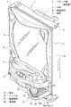
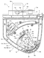
パチンコ機1は、図1に示したように、四角い環状枠2aの下辺の前面に幕板2bを設けてなる外枠2と、該外枠2の前面に装着された前面部材4と、該前面部材4の前面下方位置に設けられた遊技操作用のハンドル16と、前面部材4の前面であって前記ハンドル16の下側に遊技者側に向けて突設された受台15と、を備えている。
[Pachinko machine]
As shown in FIG. 1, the pachinko machine 1 includes an outer frame 2 in which a curtain plate 2b is provided on the front surface of the lower side of the square annular frame 2a, a front member 4 mounted on the front surface of the outer frame 2, A handle 16 for game operation provided at a lower position on the front surface of the front member 4, and a cradle 15 projecting toward the player side below the handle 16 on the front surface of the front member 4. I have.

[前面部材]
前面部材4は、外枠2の一側上下部に取り付けた蝶番部材3,3で該外枠2の前面に片開きの扉状に開閉可能なように装着されており、閉じた状態で前記幕板2bの上に位置する。
この前面部材4の正面には、ガラスや合成樹脂の透明板を装着した窓部5と、その窓部5の下側に前記遊技球を入れるために突設された球皿6と、が設けられている。
一方、前面部材4の裏側には、前記窓部5と対向する位置に装着された遊技板(図示せず)と、遊技球を貯める球タンク7その他の遊技機用機能部品を装着したいわゆる機構板8等が取り付けられている。
また、前記遊技板の正面にはガイドレール(図示せず)で円形に囲った前記遊技領域が形成されており、その遊技領域が前面部材4の前記窓部5を透して遊技者から見えるようになっている。
また、前面部材4には、遊技球を遊技領域に向けて発射させる球発射部材9が設けられている。
[Front material]
The front member 4 is attached to the front surface of the outer frame 2 by hinge members 3 and 3 attached to the upper and lower portions of one side of the outer frame 2 so as to be openable and closable in the form of a single-open door. Located on the curtain 2b.
On the front surface of the front member 4, there are provided a window portion 5 on which a transparent plate made of glass or synthetic resin is mounted, and a ball tray 6 projecting to put the game ball below the window portion 5. It has been.
On the other hand, on the back side of the front member 4, a so-called mechanism in which a game board (not shown) mounted at a position facing the window portion 5, a ball tank 7 for storing game balls and other functional parts for gaming machines are mounted. A plate 8 or the like is attached.
Further, the game area surrounded by a guide rail (not shown) in a circle is formed in front of the game board, and the game area can be seen through the window 5 of the front member 4 from the player. It is like that.
Further, the front member 4 is provided with a ball launching member 9 that launches a game ball toward the game area.

[前面部材…球発射部材]
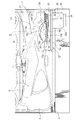
球発射部材9は、図2に示したように、遊技板の下側であって該遊技板の前面と面一の垂直面を構成するように前記前面部材4の裏側に設けた発射基板11と、該発射基板11の前面に固着した発射レール12と、前記球皿6から発射レール12上に供給される遊技球を一個ずつ打ち出す電動打球槌13と、により概略構成される。
[Front member ... Sphere launch member]
As shown in FIG. 2, the ball launching member 9 is a launching board 11 provided on the back side of the front member 4 so as to form a vertical plane that is below the game board and is flush with the front surface of the game board. And a launch rail 12 fixed to the front surface of the launch board 11 and an electric ball strut 13 for launching game balls supplied from the ball tray 6 onto the launch rail 12 one by one.

[前面部材…球発射部材…電動打球槌]
前記電動打球槌13は、図2,図5に示したように、前面部材4の裏側下方に該前面部材4との間に空間14を設けて固着した支持基板13aと、該支持基板13aの裏側(反・前面部材4側の面)に固着したロータリーソレノイド13bと、支持基板13aを貫いて前側(前面部材4側の面)に突出させた前記ロータリーソレノイド13bの出力軸13cと、支持基板13aと前面部材4の間の前記空間14内で揺動可能なようにロータリーソレノイド13bの出力軸13cに取り付けた槌本体13dと、から概略構成される。
[Front member ... Ball launching member ... Electric hitting ball]
As shown in FIGS. 2 and 5, the electric ball striking rod 13 includes a support substrate 13 a fixed by providing a space 14 between the front member 4 and the front member 4 below the front member 4, and the support substrate 13 a. A rotary solenoid 13b fixed to the back side (surface on the side opposite to the front member 4), an output shaft 13c of the rotary solenoid 13b protruding through the support substrate 13a to the front side (surface on the front member 4 side), and a support substrate 13a and 13d attached to the output shaft 13c of the rotary solenoid 13b so as to be able to swing in the space 14 between the front member 4 and 13a.

この電動打球槌13は、ロータリーソレノイド13bに電力が供給されないとき、槌本体13dが図2二点鎖線の倒れた位置にある。この状態でロータリーソレノイド13bにパルス状の電圧を印加すると、該ロータリーソレノイド13bのステータの突極(図示せず)が励磁され、ロータの突極若しくは磁極(図示せず)と勢いよく引き合い、その力で出力軸13cが回動し、槌本体13dが図2破線の発射位置に勢いよく変位する。また、パルス状の電圧は、すぐに無くなるためロータリーソレノイド13bの前記ステータの突極が消磁し、槌本体13dが図2二点鎖線の倒れた位置に戻る。   When the electric ball hitting bar 13 is not supplied with electric power to the rotary solenoid 13b, the bar body 13d is in a position where the two-dot chain line in FIG. When a pulsed voltage is applied to the rotary solenoid 13b in this state, the salient pole (not shown) of the stator of the rotary solenoid 13b is excited and vigorously attracts the salient pole or magnetic pole (not shown) of the rotor. The output shaft 13c is rotated by the force, and the bag main body 13d is vigorously displaced to the firing position indicated by the broken line in FIG. Further, since the pulse voltage disappears immediately, the stator salient pole of the rotary solenoid 13b is demagnetized, and the rod main body 13d returns to the position where the two-dot chain line in FIG.

電動打球槌13の槌本体13dの上端にはゴムなどの弾性体やコイルスプリングで形成した打撃部材13eが設けられており、槌本体13dが前記した発射位置に至ったとき該打撃部材13eが発射レール12の発射位置にある遊技球のほぼ芯を打つ。   A striking member 13e formed of an elastic body such as rubber or a coil spring is provided at the upper end of the scissors main body 13d of the electric striking ball scissors 13, and the striking member 13e fires when the scissor main body 13d reaches the firing position described above. Hit the core of the game ball at the launch position of the rail 12.

[前面部材…ハンドル+受台]
前記ハンドル16と受台15は、前記電動打球槌13の発射力を調節する発射力調節装置10の主要部を構成するものである。よって、以下に発射力調節装置10について説明する。
[Front member: Handle + cradle]
The handle 16 and the cradle 15 constitute the main part of the firing force adjusting device 10 that adjusts the firing force of the electric striking ball 13. Therefore, the firing force adjusting device 10 will be described below.

[前面部材…発射力調節装置]
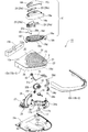
実施形態1の発射力調節装置10は、機前の下方から遊技者側に向けてほぼ水平に突設した受台15と、該受台15の上面に位置し該受台15上に設定した定点P(具体的には後述する軸孔22の中心(図5参照))を中心としたほぼ扇形の軌跡を描く状態で首振り回動可能なハンドル16と、該ハンドル16の前記首振り回動によって前記電動打球槌13の発射力を強弱させ得る調節手段17と、前記ハンドル16を前記球発射部材9の発射動作が停止するよう関連付けられた初期位置に向けて付勢するハンドル復動手段18と、前記ハンドル16を前記受台15の上面から浮かせて隙間19(図8(a),図8参照)を形成するハンドル浮揚付勢手段20と、を備えている。
[Front member ... Launch force adjusting device]
The firing force adjusting device 10 according to the first embodiment is set on the pedestal 15 that is located on the upper surface of the pedestal 15 and the pedestal 15 that protrudes almost horizontally from the lower part of the front to the player side. A handle 16 that can swing and swing in a substantially fan-shaped locus centering on a fixed point P (specifically, the center of a shaft hole 22 described later (see FIG. 5)), and the swinging of the handle 16 Adjusting means 17 capable of increasing or decreasing the firing force of the electric ball striking rod 13 by movement, and handle returning means for biasing the handle 16 toward an associated initial position so that the firing operation of the ball launching member 9 stops. 18 and a handle floating urging means 20 that forms a gap 19 (see FIGS. 8A and 8) by floating the handle 16 from the upper surface of the cradle 15.

[前面部材…発射力調節装置…受台]
前記受台15は、機前の下方、具体的には図1、図2に示したように、前面部材4の正面向かって右下にあって、そこから遊技者側に向けてほぼ水平に突出するように前面部材4の裏側から通したビス(図示せず)でビス止めされている。なお、受台15の前面部材4を挟んだ裏側には、前記球発射部材9の槌本体13dが位置している。
[Front member ... Launch force adjusting device ... Stand]
As shown in FIGS. 1 and 2, the cradle 15 is located at the lower right side of the front member 4 in front of the front member 4, and is almost horizontally toward the player side from there. It is screwed with screws (not shown) passed from the back side of the front member 4 so as to protrude. In addition, on the back side of the cradle 15 with the front member 4 interposed therebetween, the spear body 13d of the ball launching member 9 is located.

受台15の平面形状は、図5に示したように、水平な長方形を基本形としてそれを変形させたものであって、該長方形の遊技者に近い方を手前側として、遊技機の正面向かって右側に位置する手前側角部を遊技者側に引っ張って鋭角に変形させると共に、その鋭角の角部に弧状のアール部21を形成したものになっている。
また、受台15は、図10に示したように、上面部材15aと、該上面部材15aの下側の周囲を囲う側面部材15bと、該側面部材15bの下側をカバーする底面部材15cと、で構成された中空構造であり、その中空の内部が後述する部品類を組み込むための機構室15dになっている。なお、受台15の前記側面部材15bは、前面部材4に接する一辺を除いて上面部材15aと一体の内部材15b−1と、その外側を取り巻いて装飾的にカバーする外部材15b−2と、の二重構造になっている。
As shown in FIG. 5, the planar shape of the cradle 15 is obtained by deforming a horizontal rectangle as a basic shape, and facing the front of the gaming machine with the side closer to the player of the rectangle as the front side. Then, the front side corner portion located on the right side is pulled toward the player side to be deformed into an acute angle, and an arc-shaped round portion 21 is formed at the acute angle corner portion.
As shown in FIG. 10, the cradle 15 includes an upper surface member 15a, a side surface member 15b surrounding the lower side of the upper surface member 15a, and a bottom surface member 15c covering the lower side of the side surface member 15b. The hollow interior is a mechanism chamber 15d for incorporating components to be described later. The side member 15b of the cradle 15 includes an inner member 15b-1 that is integral with the upper surface member 15a except for one side that contacts the front member 4, and an outer member 15b-2 that surrounds the outer side and covers it decoratively. It has a double structure.

受台15には、上面部材15aの前記アール部21に、前記機構室15dに貫通する円形の軸孔22と、同じく機構室15dに通じる略角形の連通孔23とが穿設されている。
また、受台15には、上面部材15aに前記軸孔22を中心とする平面視円弧形で凸状(例えば山形状)に盛り上げた形態の軌道部24が複数本等間隔且つ波紋状態に並べられている。
A circular shaft hole 22 that penetrates the mechanism chamber 15d and a substantially rectangular communication hole 23 that similarly communicates with the mechanism chamber 15d are formed in the receiving base 15 in the rounded portion 21 of the upper surface member 15a.
Further, the cradle 15 has a plurality of orbital portions 24 in the form of a convex shape (for example, a mountain shape) in a plan view arc shape centered on the shaft hole 22 on the upper surface member 15a in a uniform and rippled state. Are lined up.

また、受台15には、前記軌道部24の最も外側のものに接するように前記軸孔22を中心とする弧状長孔25が穿設されている。この弧状長孔25の下面には弧状底蓋26が宛がわれており、その弧状底蓋26の遊技者に近い側の端部(以下「始端部」ともいう。)の外側に前記電動打球槌13を作動・停止させるメインスイッチ27が取り付けられている。また、弧状底蓋26の始端部には、前記メインスイッチ27のスイッチ片27aを作動させる揺動レバー28の一端が臨んでいる。   In addition, an arcuate long hole 25 centered on the shaft hole 22 is formed in the cradle 15 so as to contact the outermost part of the track portion 24. An arc-shaped bottom lid 26 is addressed to the lower surface of the arc-shaped long hole 25, and the electric ball hitting outside the end portion (hereinafter also referred to as “starting end portion”) of the arc-shaped bottom lid 26 on the side close to the player. A main switch 27 for operating / stopping the rod 13 is attached. Further, one end of a swing lever 28 that operates the switch piece 27a of the main switch 27 faces the start end portion of the arc-shaped bottom cover 26.

[前面部材…発射力調節装置…ハンドル]
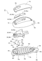
前記ハンドル16は、あたかも大型の卵をギザギザの切り口にして上下に分割し下側の半分を取り除いたような形態であり、図11に示したように、前記受台15の上面に載る底部16aと、その底部16a上にあって遊技者が手掌(しゅしょう…手の平)側を下向きにして手を載せ置くための手載せ部16bと、前記電動打球槌13を一時的に停止させ得る一時発射停止手段29と、を有する。
このハンドル16は、底部16aと手載せ部16bを別々に樹脂成形してビス16c(図13参照)により接合したものであり、その内部に前記一時発射停止手段29が組み込まれ、さらに前記したハンドル浮揚付勢手段20も組み込まれている。
[Front member ... Launch force adjusting device ... Handle]
The handle 16 has a form in which a large egg is cut into a jagged cut and is divided into upper and lower parts and the lower half is removed. As shown in FIG. 11, the bottom 16a mounted on the upper surface of the cradle 15 is formed. And a hand-launching portion 16b on the bottom portion 16a on which the player places his / her palm (shoulder: palm) side downward, and a temporary firing stop that can temporarily stop the electric ball strut 13 Means 29.
This handle 16 is obtained by separately molding a bottom portion 16a and a hand rest portion 16b and joining them with screws 16c (see FIG. 13). The temporary firing stop means 29 is incorporated therein, and the handle described above. A levitation biasing means 20 is also incorporated.

[前面部材…発射力調節装置…ハンドル…底部]
ハンドル16の前記底部16aは、前記手載せ部16bに対して印籠嵌合可能な上向きの嵌合口部16dと、長手方向の一端に延設した軸基板16eと、長手方向の他端に下向きに突設したL型屈曲片16fと、前記受台15の軌道部24に整合する逆さ凹状の摺動部16gと、を有する。前記軸基板16eには下向きに回動軸16hが突設されており、該回動軸16hが受台15の前記軸孔22に回動可能な状態に嵌合する。一方、ハンドル16の底部16aの前記摺動部16gは、前記回動軸16hを中心とする平面視円弧形で複数本等間隔且つ波紋状態に並べられており、従って、該摺動部16gは受台15の軌道部24と同じく、受台15の上面部材15aの前記軸孔22を中心とする平面視円弧形である。
[Front member ... Launch force adjusting device ... Handle ... Bottom]
The bottom portion 16a of the handle 16 has an upward fitting opening portion 16d capable of fitting with the hand-mounted portion 16b, an axial base plate 16e extending at one end in the longitudinal direction, and a downward direction at the other end in the longitudinal direction. It has a projecting L-shaped bent piece 16f, and an inverted concave sliding portion 16g that aligns with the track portion 24 of the cradle 15. A pivot shaft 16h projects downward from the shaft substrate 16e, and the pivot shaft 16h is fitted in the pivot hole 22 of the pedestal 15 so as to be pivotable. On the other hand, the sliding portion 16g of the bottom portion 16a of the handle 16 is arranged in a circular arc shape in plan view with the rotating shaft 16h as a center and arranged in a rippled state at equal intervals, and accordingly, the sliding portion 16g. Like the track portion 24 of the cradle 15, has a circular arc shape in plan view with the shaft hole 22 of the upper surface member 15 a of the cradle 15 as the center.

[前面部材…発射力調節装置…ハンドル…手載せ部]
ハンドル16の前記手載せ部16bは、遊技者が手掌側を下向きにして手を載せ置くものであって、指先を若干開いた状態の成人男性の片手でほぼ覆える程度の大きさである。
[Front member ... Launch force adjusting device ... Handle ... Hand rest part]
The hand placing portion 16b of the handle 16 is a size on which the player places his hand with the palm side facing down and can be almost covered with one hand of an adult male with the fingertip slightly opened.

[前面部材…発射力調節装置…ハンドル…一時発射停止手段]
前記ハンドル16の内部には、図11、図13に示したように、電動打球槌13を一時停止させ得る一時発射停止手段29が取り付けられている。この一時発射停止手段29は、手載せ部16bの内側にスイッチ取付部材29aを介して取り付けられたサブスイッチ29bと、手載せ部16bの外側上面に片持ち梁状に固定することによって自由端側に弾性を付与した作動片29cと、から概略構成される。そして、作動片29cの自由端側には上面にボタン凸部29dが設けられ、下面にスイッチ押え29eが突設され、図13の拡大図に示したように、前記スイッチ押え29eが手載せ部16bの通し孔16iを通って前記サブスイッチ29bのスイッチボタン29fの上面に臨んでいる。サブスイッチ29bは、例えば公知のマイクロスイッチであり、そのスイッチボタン29fが、スイッチ内のバネ(図示せず)の弾性により外部に突出する方向に常時付勢されていてその状態で内部の接点が閉じている。従って、このスイッチボタン29fが外部に突出しているとき電動打球槌13は、他の条件の成立を条件に作動し、スイッチボタン29fが下がればたとえ作動中でも停止する。
[Front member ... Launch force adjusting device ... Handle ... Temporary firing stop means]
As shown in FIGS. 11 and 13, temporary firing stopping means 29 that can temporarily stop the electric ball striking rod 13 is attached to the inside of the handle 16. The temporary firing stop means 29 includes a sub-switch 29b attached to the inner side of the hand placing portion 16b via a switch attachment member 29a and a cantilever-like fixing on the outer upper surface of the hand placing portion 16b. And an operation piece 29c provided with elasticity. Then, on the free end side of the operating piece 29c, a button convex portion 29d is provided on the upper surface, and a switch presser 29e is projected on the lower surface. As shown in the enlarged view of FIG. It faces the upper surface of the switch button 29f of the sub switch 29b through the through hole 16i of 16b. The sub switch 29b is, for example, a known micro switch, and the switch button 29f is always urged in a direction protruding outward by the elasticity of a spring (not shown) in the switch, and the internal contact is in this state. Closed. Therefore, when the switch button 29f protrudes to the outside, the electric ball striking rod 13 operates on the condition that other conditions are satisfied, and stops even if the switch button 29f is lowered.

一時発射停止手段29は以上のような構成であり、作動片29cのボタン凸部29dに力を加えない状態では作動片29cの弾性によりスイッチ押え29eがサブスイッチ29bのスイッチボタン29f上に位置しており、この状態で電動打球槌13は作動可能である。従って、この状態で前記したメインスイッチ27がONになる等、他の所定条件が整えば電動打球槌13は作動する。
一方、電動打球槌13が作動しているときに作動片29cのボタン凸部29dを指で押さえると、スイッチ押え29eが下がってサブスイッチ29bのスイッチボタン29fが押し込まれ、そうするとたとえ作動中であっても電動打球槌13は停止し、遊技球の発射が止まる。そして任意のタイミングでボタン凸部29dから指を離すと、作動片29cが自己の弾性により復動し、スイッチ押え29eが上昇してサブスイッチ29bのスイッチボタン29fも上昇し、これによって電動打球槌13が作動を再開する。
このように作動片29cのボタン凸部29dを遊技者自身が押圧・解放操作することにより、遊技球の発射を任意のタイミングで任意の時間一時的に停止させることができる。
The temporary firing stop means 29 is configured as described above. When no force is applied to the button projection 29d of the operating piece 29c, the switch presser 29e is positioned on the switch button 29f of the sub switch 29b by the elasticity of the operating piece 29c. In this state, the electric striking ball 13 is operable. Accordingly, in this state, the electric ball striking rod 13 operates when other predetermined conditions such as the main switch 27 is turned on.
On the other hand, when the electric ball striking rod 13 is operating, if the button convex portion 29d of the operating piece 29c is pressed with a finger, the switch presser 29e is lowered and the switch button 29f of the sub switch 29b is pressed. However, the electric hitting ball 13 stops and the game ball stops firing. When the finger is released from the button convex portion 29d at an arbitrary timing, the operating piece 29c moves backward due to its own elasticity, the switch presser 29e rises, and the switch button 29f of the sub switch 29b also rises. 13 resumes operation.
As described above, when the player himself presses and releases the button convex portion 29d of the operating piece 29c, the launch of the game ball can be temporarily stopped at an arbitrary timing for an arbitrary time.

なお、図11、図13において16jは前記作動片29cの上面を覆うように手載せ部16bに装着したカバー部材、16kは該カバー部材16jに設けた貫通長孔であり、該貫通長孔16kから作動片29cのボタン凸部29dがカバー部材16jの外に出る。このカバー部材16jは導電構造のタッチスイッチになっており、該カバー部材16jに遊技者の手が触れていることを検知し、手が触れている場合にのみ前記電動打球槌13の作動を可能とする。   11 and 13, 16j is a cover member attached to the hand-mounted portion 16b so as to cover the upper surface of the operating piece 29c, 16k is a through long hole provided in the cover member 16j, and the through long hole 16k The button projection 29d of the operating piece 29c comes out of the cover member 16j. The cover member 16j is a touch switch having a conductive structure. When the player's hand is touching the cover member 16j, the electric hitting basket 13 can be operated only when the hand is touching. And

また、図11、図13において16mは手載せ部16bの反サブスイッチ29b側の端部から下向きに突設した水平断面コ字状の配線支柱であり、該配線支柱16mを受台15の前記連通孔23に差し込んでその先端を前記機構室15dに臨ませると共に、その配線支柱16mの中を通って前記サブスイッチ29bの配線(図示せず)やカバー部材16jのタッチスイッチの配線(図示せず)が機構室15dに引き込まれる。   11 and 13, reference numeral 16m denotes a wiring post having a U-shaped horizontal section projecting downward from an end of the hand mounting portion 16b on the side opposite to the sub switch 29b. The tip of the communication hole 23 is inserted into the mechanism chamber 15d, and the wiring of the sub switch 29b (not shown) and the wiring of the touch switch of the cover member 16j (not shown) pass through the wiring column 16m. Are pulled into the mechanism chamber 15d.

[前面部材…発射力調節装置…ハンドルと受台]
前記ハンドル16は、底部16aの一端の軸基板16eに突設した前記回動軸16hを前記受台15の軸孔22に挿通し、一方、底部16aの他端に突設したL型屈曲片16fを受台15の弧状長孔25に通した状態で受台15の上面に設置されている。ハンドル16は、前記のように指先を若干開いた状態の成人男性の片手でほぼ覆える程度の大きさであり、従って操作姿勢で前記受台15の上面にも操作する手の一部が載る。
ハンドル16は、図5に示したように、首振り回動の中心たる前記回動軸16h(=軸孔22)が遊技者寄りの位置に配置されると共に扇形の軌跡の円弧側が反遊技者側(前枠4の前面側)に向かう向きになっている。
[Front member ... Launch force adjusting device ... Handle and cradle]
The handle 16 has an L-shaped bent piece projecting from the shaft hole 22 of the receiving base 15 through the pivot shaft 16h projecting from the shaft substrate 16e at one end of the bottom portion 16a, and projecting from the other end of the bottom portion 16a. 16 f is installed on the upper surface of the cradle 15 with the arc-shaped long hole 25 of the cradle 15 passing therethrough. The handle 16 is large enough to be covered with one hand of an adult male with the fingertip slightly opened as described above. Therefore, a part of the operating hand is also placed on the upper surface of the cradle 15 in the operating posture. .
As shown in FIG. 5, the handle 16 has the pivot shaft 16h (= shaft hole 22), which is the center of swing motion, arranged at a position close to the player, and the arc side of the fan-shaped locus is the anti-player. The direction is toward the side (the front side of the front frame 4).

受台15の上面にハンドル16を設置した状態で、受台15の軌道部24の出っ張りとハンドル16の摺動部16gの凹みが緩やかな嵌め合い状態で合わさっている。受台15の軌道部24とハンドル16の摺動部16gは中心(回動軸16hと軸孔22)を同じくする平面視円弧形であるから、ハンドル16は、受台15の軌道部24と摺動部16gとが合わさったまま回動軸16h(=軸孔22)の中心を定点Pとしてその定点Pを中心に首振り回動可能である。   In a state where the handle 16 is installed on the upper surface of the cradle 15, the protrusion of the track portion 24 of the cradle 15 and the recess of the sliding portion 16 g of the handle 16 are combined in a loosely fitted state. Since the track portion 24 of the cradle 15 and the sliding portion 16g of the handle 16 have a circular arc shape in plan view with the same center (the rotation shaft 16h and the shaft hole 22), the handle 16 has the track portion 24 of the cradle 15. The center of the rotation shaft 16h (= shaft hole 22) can be swung around the fixed point P with the center of the rotation shaft 16h (= shaft hole 22) as the sliding portion 16g is put together.

一方、ハンドル16の底部16aの一端に下向き突設したL型屈曲片16fは、前記軌道部24や摺動部16gと中心(回動軸16h、軸孔22)を同じくする平面視円弧形の弧状長孔25の中を移動するため、ハンドル16の首振り回動を妨げない。さらにL型屈曲片16fは、図13の拡大図に示したように受台15の弧状長孔25の開口縁に内側から引っ掛かるように位置設定されており、このL型屈曲片16fの引っ掛かりによりハンドル16の一端が浮き上がらないようになっている。なお、受台15の弧状長孔25の開口縁の下面沿いには下向きのリブ25aが突設されており、ハンドル16のL型屈曲片16fとの接触部をほぼ線状にして摩擦を低減し、もってハンドル16の軽やかな動きが妨げられないようにしてある。   On the other hand, an L-shaped bent piece 16f projecting downward at one end of the bottom portion 16a of the handle 16 has a circular arc shape in plan view that has the same center (rotating shaft 16h, shaft hole 22) as the track portion 24 and the sliding portion 16g. Therefore, the swinging rotation of the handle 16 is not hindered. Furthermore, as shown in the enlarged view of FIG. 13, the L-shaped bent piece 16f is positioned so as to be hooked from the inner side to the opening edge of the arc-shaped elongated hole 25 of the receiving base 15, and the L-shaped bent piece 16f is caught by the hook. One end of the handle 16 is prevented from floating. A downward rib 25a protrudes along the lower surface of the opening edge of the arc-shaped long hole 25 of the cradle 15, and the contact portion of the handle 16 with the L-shaped bent piece 16f is substantially linear to reduce friction. Thus, the light movement of the handle 16 is not hindered.

また、L型屈曲片16fは、ハンドル16が最も遊技者側に近寄った図5実線の位置にあるとき、前記メインスイッチ27の揺動レバー28に作用して該メインスイッチ27をOFFにする。こうしてメインスイッチ27がOFFになると電動打球槌13は作動せず、球発射部材9の発射動作は停止する。
従って本実施形態において、受台15上での最も遊技者側に近寄った図5実線のハンドル16の位置が、球発射部材9の発射動作が停止するよう関連付けられた初期位置である。
Further, the L-shaped bent piece 16f acts on the swing lever 28 of the main switch 27 to turn off the main switch 27 when the handle 16 is at the position of the solid line in FIG. 5 closest to the player side. Thus, when the main switch 27 is turned off, the electric ball striking rod 13 does not operate and the firing operation of the ball launching member 9 stops.
Therefore, in the present embodiment, the position of the handle 16 shown by the solid line in FIG. 5 that is closest to the player side on the cradle 15 is the initial position associated with the firing operation of the ball launching member 9 being stopped.

[前面部材…発射力調節装置…調節手段]
前記球発射部材9の発射力を強弱させる調節手段17は、球発射部材9の前記ロータリーソレノイド13bに印加するパルス状の電圧値を変更可能な可変抵抗器であり、図10、図12に示したように、略円柱形を呈する抵抗器本体17aと、その抵抗器本体17aの中心から突出する調節軸17bと、を有する。そして、前記受台15の上面部材15aの裏側(下面)に、該上面部材15aにビス着されている支持部材30を介して前記調節軸17bを上向きにした状態で取り付けられている。なお、調節手段17の抵抗器本体17aは、支持部材30の下側に出っ張った状態になっているため、受台15の底面部材15cに長円形のカップ部15eを設けてその中に抵抗器本体17aが収まるようになっている。
[Front member ... Launch force adjusting device ... Adjusting means]
The adjusting means 17 for increasing or decreasing the firing force of the ball launching member 9 is a variable resistor capable of changing a pulsed voltage value applied to the rotary solenoid 13b of the ball launching member 9, and is shown in FIGS. As described above, the resistor body 17a has a substantially cylindrical shape, and the adjustment shaft 17b protrudes from the center of the resistor body 17a. And it is attached to the back side (lower surface) of the upper surface member 15a of the cradle 15 with the adjustment shaft 17b facing upward via a support member 30 screwed to the upper surface member 15a. Since the resistor main body 17a of the adjusting means 17 protrudes from the lower side of the support member 30, an oval cup portion 15e is provided on the bottom surface member 15c of the cradle 15 and a resistor is provided therein. The main body 17a is accommodated.

[前面部材…発射力調節装置…調節手段+ハンドル]
前記調節手段17と前記ハンドル16は、図6、図7、図12、図13に示したように、略扇形の原動内歯車31と、略扇形の従動平歯車32との組み合わせである歯車伝動機構により連結されている。
[Front member ... Launch force adjusting device ... Adjusting means + handle]
As shown in FIGS. 6, 7, 12, and 13, the adjusting means 17 and the handle 16 are gear transmissions that are combinations of a substantially sector-shaped driving internal gear 31 and a substantially sector-shaped driven spur gear 32. It is connected by a mechanism.

前記原動内歯車31は、前記受台15の上面部材15aの裏側に沿う位置にあって前記ハンドル16の回動軸16hの下端にビスにより固着されており、従ってハンドル16と一体に首振り回動可能である。この原動内歯車31は、円周部分の周壁31aの内側に内歯車を構成する歯31b,31b…を有すると共に周壁31aの外側にフランジ片31cを有し、該フランジ片31cが、受台15の上面部材15aに軸着されている回転ローラ33の溝33aの間を通るようになっている。従って原動内歯車31の重量バランスが扇形であるが故に周壁31a側に偏っていても、回転ローラ33の支えにより周壁31a側が下がったりふらついたりするおそれがない。よって原動内歯車31の首振り回動が安定する。   The driving internal gear 31 is located at a position along the back side of the upper surface member 15a of the cradle 15 and is fixed to the lower end of the rotating shaft 16h of the handle 16 with a screw. It is possible to move. This drive internal gear 31 has teeth 31b, 31b,... Constituting the internal gear on the inner side of the peripheral wall 31a of the circumferential portion, and has a flange piece 31c on the outer side of the peripheral wall 31a. It passes between the grooves 33a of the rotating roller 33 that is pivotally attached to the upper surface member 15a. Therefore, even if the weight balance of the driving internal gear 31 is fan-shaped, even if it is biased toward the peripheral wall 31a, there is no possibility that the peripheral wall 31a is lowered or fluctuated by the support of the rotating roller 33. Therefore, the swinging rotation of the driving internal gear 31 is stabilized.

一方、従動平歯車32は、前記原動内歯車31の下に位置し、扇の中心相当部位に突設した下向きの軸筒部32aを前記調節手段17の調節軸17bの上端に被せた状態で固着されており、調節軸17bと一体に回動する。該従動平歯車32の外周には平歯車を構成する歯32b,32b…が形成されており、その歯32b,32b…と前記原動内歯車31の歯31b,31b…が図6、図7に示したように噛み合っている。従って原動内歯車31がハンドル16と一体に図6から図7のように首振り回動すると、その回動が原動内歯車31から従動平歯車32に伝わって調節軸17bが回るため、調節手段17の電気抵抗が変わる。   On the other hand, the driven spur gear 32 is located below the driving internal gear 31 and is in a state where a downward shaft tube portion 32a projecting from a portion corresponding to the center of the fan is placed on the upper end of the adjusting shaft 17b of the adjusting means 17. It is fixed and rotates integrally with the adjusting shaft 17b. .. Are formed on the outer periphery of the driven spur gear 32. The teeth 32b, 32b... And the teeth 31b, 31b of the driving internal gear 31 are shown in FIGS. Engage as shown. Therefore, when the driving internal gear 31 is swung and pivoted integrally with the handle 16 as shown in FIGS. 6 to 7, the rotation is transmitted from the driving internal gear 31 to the driven spur gear 32 and the adjusting shaft 17b rotates. 17 electrical resistance changes.

[前面部材…発射力調節装置…ハンドル復動手段]
前記ハンドル復動手段18は、前記ハンドル16を前記初期位置、すなわち前記球発射部材9の発射動作が停止するよう関連付けられた位置に向けて付勢するものであり、前記従動平歯車32の軸筒部32aの外周に装着した捩りコイルバネ18aで構成されている。該捩りコイルバネ18aは、両端のバネ軸18b,18cを従動平歯車32の底面と前記支持部材30に夫々係止させることにより、従動平歯車32を図6、図7において反時計回りに付勢するようになっている。この捩りコイルバネ18aの付勢力が、従動平歯車32から原動内歯車31に伝わってハンドル16を初期位置に向かわせる回転力となる。従ってハンドル16が遊技者によって初期位置から離れた位置に動かされても、遊技者がハンドル16から手を離せば、ハンドル復動手段18の捩りコイルバネ18aの付勢により初期位置に自動的に復動する。
[Front member ... Launch force adjusting device ... Handle return means]
The handle returning means 18 urges the handle 16 toward the initial position, that is, the associated position so that the firing operation of the ball launching member 9 stops, and the shaft of the driven spur gear 32 It is comprised by the torsion coil spring 18a with which the outer periphery of the cylinder part 32a was mounted | worn. The torsion coil spring 18a urges the driven spur gear 32 counterclockwise in FIGS. 6 and 7 by engaging the spring shafts 18b and 18c at both ends with the bottom surface of the driven spur gear 32 and the support member 30, respectively. It is supposed to be. The urging force of the torsion coil spring 18a is transmitted from the driven spur gear 32 to the driving internal gear 31 and becomes a rotational force that moves the handle 16 to the initial position. Therefore, even if the handle 16 is moved to a position away from the initial position by the player, if the player releases his / her hand from the handle 16, the handle 16 is automatically returned to the initial position by the urging of the torsion coil spring 18a. Move.

なお、実施形態のハンドル復動手段18は、上記のように捩りコイルバネ18aで構成したため、ハンドル16から遊技者の手が離れた瞬間に勢いよく戻りすぎるおそれがある。そこで実施形態では、ハンドル16の初期位置への復動が緩やかに行われるように緩衝手段18dが設けてある。この緩衝手段18dは、例えばオイルの粘性抵抗で制動力を発生させるようにした回転系のダンパーであり、ダンパー本体18eを図13に示したように前記支持部材30の上面側に固着すると共に、ダンパー本体18eの上部に突出させたピニオンギヤ18fと前記従動平歯車32の下面に形成した内歯車32cとを噛合させ、もってハンドル復動手段18の捩りコイルバネ18aによって従動平歯車32が初期位置に向かって復動するとき、オイルの粘性抵抗による制動力をピニオンギヤ18fに作用させ、そうしてハンドル16をゆっくりと復動させる。   In addition, since the handle backward moving means 18 of the embodiment is configured by the torsion coil spring 18a as described above, there is a possibility that the handle will return too vigorously at the moment when the player's hand leaves the handle 16. Therefore, in the embodiment, the buffering means 18d is provided so that the return movement of the handle 16 to the initial position is performed gently. The dampening means 18d is, for example, a rotary damper that generates a braking force by the viscous resistance of oil. The damper main body 18e is fixed to the upper surface side of the support member 30 as shown in FIG. The pinion gear 18f protruded from the upper portion of the damper main body 18e and the internal gear 32c formed on the lower surface of the driven spur gear 32 are engaged with each other, so that the driven spur gear 32 is moved to the initial position by the torsion coil spring 18a of the handle returning means 18. When returning in this manner, a braking force due to the viscous resistance of the oil is applied to the pinion gear 18f, so that the handle 16 is slowly returned.

[前面部材…発射力調節装置…ハンドル浮揚付勢手段]
前記ハンドル浮揚付勢手段20は、ハンドル16の手載せ部16bに遊技者の手が載っていないときに、図8(a)に示したように、ハンドル16の底部16aを受台15の上面から浮かせて隙間19を形成するためのものである。
このハンドル浮揚付勢手段20は、図11に示したように、中央下面に二本の固定ピン20a,20aを突設した固定主板20bと、その固定主板20bの両横に延設した弾性翼片20c,20cと、該弾性翼片20cの端部下面に突設した脚片20d,20dと、を備え、前記固定ピン20a,20aをハンドル16の底部16aに形成した受筒部16n,16nに嵌合させて固定主板20bを固定すると共に、弾性翼片20c,20cの脚片20d,20dをハンドル16の底部16aに開設した脚通孔16p,16pから受台15の上面(一対の軌道部24,24同士の間)に突出させ、そうしてハンドル16の底部16aを受台15の上面から浮かせるようにしたものである。このときハンドル16は、ハンドル浮揚付勢手段20の弾性翼片20c,20cの弾性によって支えられているのであり、従ってハンドル浮揚付勢手段20は、少なくともハンドル16の重量を支えるに十分な強さを有する。
[Front member ... Launch force adjusting device ... Handle float urging means]
When the player's hand is not placed on the hand placement portion 16b of the handle 16, the handle levitation urging means 20 places the bottom portion 16a of the handle 16 on the upper surface of the cradle 15 as shown in FIG. This is for forming the gap 19 by floating.
As shown in FIG. 11, the handle levitation urging means 20 includes a fixed main plate 20b having two fixed pins 20a and 20a projecting from the lower surface of the center, and an elastic wing extending on both sides of the fixed main plate 20b. Receiving portions 20c, 20c and leg pieces 20d, 20d projecting on the lower surface of the end portion of the elastic wing piece 20c, and receiving tube portions 16n, 16n formed on the bottom portion 16a of the handle 16 with the fixing pins 20a, 20a. To fix the fixed main plate 20b, and the leg pieces 20d, 20d of the elastic wing pieces 20c, 20c from the leg through holes 16p, 16p provided in the bottom portion 16a of the handle 16 to the upper surface (a pair of tracks). The bottom portion 16a of the handle 16 is made to float from the upper surface of the cradle 15. At this time, the handle 16 is supported by the elasticity of the elastic blades 20c, 20c of the handle levitation biasing means 20, and therefore the handle levitation biasing means 20 is strong enough to support at least the weight of the handle 16. Have

このようにハンドル16が、ハンドル浮揚付勢手段20の脚片20d,20dで支えられている状態では、ハンドル浮揚付勢手段20を潤滑性に優れた樹脂(例えばフッ素樹脂)で形成しておけば受台15との摩擦抵抗を小さくすることができるから、前記ハンドル復動手段18によるハンドル16の復動が軽やかに行える効果がある。
また、そのような潤滑性に優れた樹脂でハンドル浮揚付勢手段20を形成しない場合でも、ハンドル16の底部16aと受台15の面同士の全面接触を回避することにより、ハンドル16の底部16aや受台15の汚れに起因する摩擦抵抗の増大の影響を受けにくくすることができるから、どちらにしてもハンドル復動手段18によるハンドル16の復動が軽やかに行える効果がある。
As described above, when the handle 16 is supported by the leg pieces 20d and 20d of the handle levitation urging means 20, the handle levitation urging means 20 may be formed of a resin having excellent lubricity (for example, a fluororesin). In this case, since the frictional resistance with the cradle 15 can be reduced, there is an effect that the return movement of the handle 16 by the handle return means 18 can be performed lightly.
Further, even when the handle floating urging means 20 is not formed of such a resin having excellent lubricity, the bottom 16a of the handle 16 can be avoided by avoiding the entire contact between the bottom 16a of the handle 16 and the surface of the receiving base 15. In addition, since it can be made less susceptible to an increase in frictional resistance caused by dirt on the cradle 15, in any case, there is an effect that the handle 16 can be easily moved backward by the handle returning means 18.

なお、上記のようにハンドル復動手段18によるハンドル16の復動が軽やかに行えるということは、ハンドル復動手段18の捩りコイルバネ18aのばね定数を小さくすることができる、ということを意味するものであり、そうした場合にはハンドル16の捩りコイルバネ18aの付勢に抗する方向(図5において実線位置から二点鎖線位置に回動させる方向)の操作が小さい力で行える効果、ひいては遊技者の疲労度を軽減させ得る効果にもつながる。   Note that the fact that the handle 16 can be easily moved backward by the handle returning means 18 as described above means that the spring constant of the torsion coil spring 18a of the handle returning means 18 can be reduced. In such a case, the operation in the direction against the urging of the torsion coil spring 18a of the handle 16 (the direction of turning from the solid line position to the two-dot chain line position in FIG. 5) can be performed with a small force. It also leads to an effect that can reduce the degree of fatigue.

一方、ハンドル浮揚付勢手段20は、ハンドル16の手載せ部16bに遊技者が手を載せた場合に、その手の重量の増加分に抗しきれない強さ、つまり前記弾性翼片20c,20cが撓むように設定されている。従ってハンドル16の手載せ部16bに遊技者が手を載せると、前記のようにハンドル16を支えていたハンドル浮揚付勢手段20の前記弾性翼片20c,20cが撓んで図8(b)のように固定主板20bとともにハンドル16が下がり、ハンドル16の底部16aと受台15の上面とが接触する。そうするとハンドル16の底部16aと受台15の上面とが全面で接触するため、前記ハンドル復動手段18の付勢に抗してハンドル16を任意の位置に停止させておくことが容易になる。   On the other hand, when the player places his / her hand on the hand rest 16b of the handle 16, the handle levitation urging means 20 is strong enough to resist the increase in the weight of the hand, that is, the elastic wing piece 20c, 20c is set to bend. Therefore, when the player places his / her hand on the hand rest 16b of the handle 16, the elastic wing pieces 20c and 20c of the handle levitation urging means 20 supporting the handle 16 as described above are bent, and as shown in FIG. Thus, the handle 16 is lowered together with the fixed main plate 20b, and the bottom 16a of the handle 16 and the upper surface of the cradle 15 come into contact with each other. As a result, the bottom 16a of the handle 16 and the upper surface of the cradle 15 come into contact with each other, so that it is easy to stop the handle 16 at an arbitrary position against the urging force of the handle returning means 18.

[前面部材…発射力調節装置…その他]
図12、図13において、34は受台15の前記アール部21に設けた振動ユニットである。該振動ユニット34は、受台15の内部に固定した基台34aと、その基台34aに上向きに取り付けた左右1対の支持スプリング34b,34bと、その支持スプリング34b,34bによって上下動可能に支持される振動部材34cと、該振動部材34cの上面に取り付けられ、受台15の内側からアール部21の上面に向けて突出するように形成した受け部34dとからなる。
[Front member ... Laser force adjusting device ... Others]
12 and 13, reference numeral 34 denotes a vibration unit provided in the rounded portion 21 of the cradle 15. The vibration unit 34 can be moved up and down by a base 34a fixed inside the cradle 15, a pair of left and right support springs 34b and 34b attached to the base 34a, and the support springs 34b and 34b. The vibration member 34c is supported, and the receiving portion 34d is attached to the upper surface of the vibration member 34c and is formed so as to protrude from the inner side of the receiving base 15 toward the upper surface of the round portion 21.

前記受け部34dは、図5のように受台15のアール部21に沿う平面視円弧状であって、ハンドル16の軸基板16eの周りに突出していて、遊技者がハンドル16を操作する際に手の平の手首に近い部位が載るようになっている。
従って前記振動部材34cを作動させることにより、振動ユニット34の振動が受け部34dを介して遊技者の手に伝わるから、例えば遊技の内容に合わせて振動部材34cを適宜なタイミングで作動させれば、遊技の興趣を増大させることができ、或は振動により遊技者の手の疲れをほぐす用途に使用することもできる。なお、振動ユニット34をマッサージ機的な用途に使用する場合は、遊技者が自由に操作可能なように遊技者向けの振動スイッチを設けるとよい。
The receiving portion 34d has a circular arc shape in plan view along the rounded portion 21 of the pedestal 15 as shown in FIG. 5 and protrudes around the shaft substrate 16e of the handle 16, and when the player operates the handle 16 The part close to the wrist of the palm of the hand is placed.
Accordingly, by operating the vibration member 34c, the vibration of the vibration unit 34 is transmitted to the player's hand through the receiving portion 34d. For example, if the vibration member 34c is operated at an appropriate timing in accordance with the content of the game. It is possible to increase the interest of the game, or it can be used for the purpose of relieving the player's hand fatigue by vibration. When the vibration unit 34 is used for a massage machine, a vibration switch for the player may be provided so that the player can freely operate.

[前面部材…発射力調節装置の作動説明]
遊技開始前のパチンコ機は、図1の状態であり、発射力調節装置10のハンドル16が、図5のようにハンドル復動手段18の付勢により遊技者側に最も近寄った初期位置にある。ハンドル16が初期位置にある状態では、図5、図6のようにハンドル16のL型屈曲片16fと揺動レバー28の作用により受台15の内部に設けた前記メインスイッチ27がOFFになっていて、前記球発射部材9が停止している。そしてこのときハンドル16は、図8(a)、図13のようにハンドル浮揚付勢手段20の弾性翼片20c,20cの弾性により、受台15の上面との間に隙間19を保った状態で支えられている。
[Front member: Explanation of operation of firing force adjusting device]
The pachinko machine before the start of the game is in the state shown in FIG. 1, and the handle 16 of the firing force adjusting device 10 is in the initial position closest to the player side by the urging of the handle returning means 18 as shown in FIG. . In the state where the handle 16 is in the initial position, the main switch 27 provided inside the cradle 15 is turned off by the action of the L-shaped bent piece 16f of the handle 16 and the swing lever 28 as shown in FIGS. The ball launching member 9 is stopped. At this time, the handle 16 is in a state in which a gap 19 is maintained between the handle 16 and the upper surface of the cradle 15 by the elasticity of the elastic wing pieces 20c and 20c of the handle levitation urging means 20 as shown in FIGS. It is supported by.

そこでまず、前枠4の球皿6に遊技球を投入し、受台15のアール部21にある前記受け部34dに右手の手の平の手首近くの部位を載せ、手の平と指をハンドル16の手載せ部16bに載せる。このとき遊技者の例えば小指を含む右手の縁全体を受台15の上面に載せるか、その逆に親指側を受台15の上面に載せるか、或は親指と小指を受台15の上面に載せ、手載せ部16bには手の平と受台15に載せた指以外の指を載せる。   Therefore, first, a game ball is put into the ball tray 6 of the front frame 4, a portion near the wrist of the palm of the right hand is placed on the receiving portion 34 d in the rounded portion 21 of the receiving base 15, and the palm and fingers are placed on the hand of the handle 16 Place on the mounting portion 16b. At this time, the entire edge of the right hand of the player including the little finger, for example, is placed on the upper surface of the cradle 15, or the thumb side is placed on the upper surface of the cradle 15, or the thumb and little finger are placed on the upper surface of the cradle 15. A finger other than the palm placed on the cradle 15 and the cradle 15 is placed on the placing and hand placing portion 16b.

なお、ハンドル16に手を載せた段階で、その手の重みにより前記ハンドル浮揚付勢手段20の弾性翼片20c,20cが図8(b)のように撓むため、ハンドル16が下がって底部16aと受台15の上面が接触する。また、ハンドル16に載せた手がカバー部材16jに触れるため、カバー部材16jのタッチスイッチがONになる。   When the hand is placed on the handle 16, the elastic wing pieces 20c and 20c of the handle levitation urging means 20 are bent as shown in FIG. 16a and the upper surface of the receiving stand 15 contact. Further, since the hand placed on the handle 16 touches the cover member 16j, the touch switch of the cover member 16j is turned on.

次に、操作する右手を、主として手首を中心に図5において時計回りに動かしてハンドル16に力を加えると、ハンドル16が定点Pたる回動軸16hを中心に回動する。ハンドル16のこの回動により図7のようにL型屈曲片16fが揺動レバー28から離れるため、メインスイッチ27のスイッチ片27aが押圧から解放され、メインスイッチ27がONになる。これにより球発射部材9の電動打球槌13が打球動作を開始する。   Next, when the right hand to be operated is moved clockwise in FIG. 5 mainly around the wrist and a force is applied to the handle 16, the handle 16 rotates about the rotation shaft 16h which is a fixed point P. By this rotation of the handle 16, the L-shaped bent piece 16f is separated from the swing lever 28 as shown in FIG. 7, so that the switch piece 27a of the main switch 27 is released from being pressed and the main switch 27 is turned on. Thereby, the electric ball striking rod 13 of the ball launching member 9 starts the ball hitting operation.

なお、通常、球皿6に投入された遊技球は、球発射部材9の電動打球槌13と連動する球供給装置(図示せず)によって発射レール12の発射部の手前で止められており、電動打球槌13が打球動作を開始すると、その動きに連動して1個ずつ発射レール12の発射部に供給される。   Normally, the game ball thrown into the ball tray 6 is stopped in front of the launching portion of the launch rail 12 by a ball supply device (not shown) linked to the electric ball striking rod 13 of the ball launching member 9. When the electric striking ball 13 starts a hitting operation, it is supplied one by one to the launching portion of the launching rail 12 in conjunction with the movement.

一方、ハンドル16の回動は、回動軸16hから原動内歯車31と従動平歯車32を経て調節手段17の調節軸17bに歯車伝動機構のギヤ比に従い伝わるから、ハンドル16の回動量に応じて調節軸17bが回転し、可変抵抗器の電気抵抗が変化する。これにより電動打球槌13のロータリーソレノイド13bに加わる電圧が変化し、槌本体13dの打撃力が変化する。従って遊技者は、打撃力が狙った強さになったとき、その位置でハンドル16を止めればよい。   On the other hand, the rotation of the handle 16 is transmitted from the rotation shaft 16h through the driving internal gear 31 and the driven spur gear 32 to the adjustment shaft 17b of the adjusting means 17 according to the gear ratio of the gear transmission mechanism. As a result, the adjusting shaft 17b rotates and the electric resistance of the variable resistor changes. As a result, the voltage applied to the rotary solenoid 13b of the electric ball striking rod 13 changes, and the striking force of the rod main body 13d changes. Therefore, the player only has to stop the handle 16 at the position when the hitting force becomes the targeted strength.

次に、遊技球を発射している状態で、遊技球の発射を一時的に停止させたい場合は、ハンドル16の手載せ部16bに突出しているボタン凸部29dを例えば右手人差し指で押す。そうするとハンドル16の中にあるサブスイッチ29bがOFFとなり、その間、電動打球槌13が停止する。そして、適宜なタイミングでボタン凸部29dから指を離すと、前記サブスイッチ29bがONとなり、電動打球槌13の作動が再開する。その間、ハンドル16を動かさなかった場合には、停止前と同じ打撃力で再開できる。   Next, when it is desired to temporarily stop the launch of the game ball while the game ball is being fired, the button convex portion 29d projecting from the hand placement portion 16b of the handle 16 is pushed with, for example, the right hand index finger. Then, the sub switch 29b in the handle 16 is turned OFF, and the electric ball striking rod 13 stops during that time. Then, when the finger is released from the button convex portion 29d at an appropriate timing, the sub switch 29b is turned on, and the operation of the electric ball striking rod 13 is resumed. In the meantime, if the handle 16 is not moved, it can be resumed with the same striking force as before the stop.

次に、遊技中に遊技者がハンドル16から完全に手を離すと、まずハンドル16のカバー部材16jのタッチスイッチがOFFになるからその時点で電動打球槌13が停止し、それと同時にハンドル16の底部16aからハンドル浮揚付勢手段20の脚片20dが突出してハンドル16の底部16aが受台15の上面から離れる。そして、ハンドル復動手段18の捩りコイルバネ18aの付勢と緩衝手段18dの働きによりハンドル16が初期位置に緩やかに復動し、ハンドル16のL型屈曲片16fが揺動レバー28に当たってメインスイッチ27がOFFとなる。   Next, when the player completely removes his / her hand from the handle 16 during the game, first, the touch switch of the cover member 16j of the handle 16 is turned off. The leg piece 20 d of the handle floating urging means 20 protrudes from the bottom portion 16 a and the bottom portion 16 a of the handle 16 is separated from the upper surface of the cradle 15. Then, the handle 16 is gently moved back to the initial position by the urging of the torsion coil spring 18a of the handle returning means 18 and the action of the buffering means 18d, and the L-shaped bent piece 16f of the handle 16 hits the swing lever 28 to contact the main switch 27. Is turned off.

[受台の保護]
しかして遊技者は、遊技結果に苛立つ場合があり、その遊技者が腰掛けた姿勢のまま力任せに受台15を叩くおそれがある。これにより受台15に下向きの大きな外力が作用して破損に至るおそれがある。そのような遊技者による外力から受台15を護るための受台保護手段1,2が、パチンコ機1に施されている。
[Protection of cradle]
Therefore, the player may be frustrated with the game result, and there is a risk that the player may hit the cradle 15 with the power left in the sitting posture. As a result, a large downward external force may act on the cradle 15 to cause damage. The pachinko machine 1 is provided with cradle protection means 1 and 2 for protecting the cradle 15 from such external force by the player.

[受台保護手段1]
受台保護手段1は、上記パチンコ機1について、外枠2の幕板2bと、受台15とを棚受け状の支持部材35で分離可能な状態に連繋させることにより、前記した受台15に加わる下向きの外力を幕板2bに分散させ得るようにしたものである。
[Balance protection means 1]
The cradle protector 1 connects the curtain plate 2b of the outer frame 2 and the cradle 15 in a state in which the pachinko machine 1 can be separated by a shelf-supporting support member 35, so that the cradle 15 described above is connected. The downward external force applied to the screen can be distributed to the curtain plate 2b.

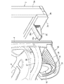
前記支持部材35は、図3、図9に示したように、受台15の下面に一体且つ斜め下向きに固着されており、後端の当り面35aが前面部材4を閉じた状態で幕板2bの正面に当接し、そうして幕板2bと受台15とを分離可能な状態に連繋させる。なお、図3において符合36は、幕板2bの正面に突設された支持部材35のための逃げ止め手段であり、これにより支持部材35が幕板2bに当たった状態で下に逃げる動きを抑制する。この逃げ止め手段としては、幕板2b側に凹みを設けて支持部材35の当り面をその凹みに嵌め入れるようにしてもよい。   As shown in FIGS. 3 and 9, the support member 35 is fixed integrally and obliquely downward to the lower surface of the cradle 15, and the curtain plate is in a state where the contact surface 35 a at the rear end closes the front member 4. 2b, and the curtain plate 2b and the cradle 15 are connected in a separable state. In FIG. 3, reference numeral 36 denotes escape means for the support member 35 projecting from the front surface of the curtain plate 2 b, whereby the movement of the support member 35 escaping downward in a state where it hits the curtain plate 2 b. Suppress. As the escape preventing means, a recess may be provided on the curtain plate 2b side, and the contact surface of the support member 35 may be fitted into the recess.

このように幕板2bと受台15とを棚受け状の支持部材35で連繋させたことにより、受台15に加わる下向きの外力が支持部材35を介して幕板2bに分散されるため、受台15の強度を確実に高めることができる。   By connecting the curtain plate 2b and the cradle 15 with the shelf-supporting support member 35 in this way, the downward external force applied to the cradle 15 is distributed to the curtain plate 2b via the support member 35. The strength of the cradle 15 can be reliably increased.

なお、受台15は、前記のように前面部材4の下辺ぎりぎりの位置にあるため、該受台15の下面に支持部材35を固着した場合には、外枠2から外した状態の前面部材4を起立させて保管、輸送等を行う際に、支持部材35の出っ張りで前面部材4の起立姿勢が大きく左右方向に傾き不安定になる可能性がある。
斯かる不安定さを改善する必要がある場合には、図14のように支持部材35を受台15に対して折り畳み可能とするか、或は図示しないが、支持部材35を受台15に対してビス等により着脱可能に取り付けるとよい。そうすることにより、前面部材4を単体で保管、輸送等する場合には、支持部材35を折り畳み又は取り外して受台15の下面の出っ張りを抑制し、外枠2に取り付けた状態で支持部材35を受台15の下面に突出させるようにすることができる。ちなみに、図14の支持部材35は、受台15の下面に突設した軸受150に軸350で軸着されていて自己のバランス又はバネ等の付勢で図14(a)の状態に回動しており、前面部材4を単体で地面G(図14(b)二点鎖線参照)に置くと該前面部材4の重量で自動的に折り畳まれる。
また、前面部材4のみを起立させて保管、輸送等を行う際に支持部材35が下に出っ張る対策として、実施形態1では該支持部材35の下側に弧状面35rを設けるようにしてある。これにより前面部材4を輸送等する取り扱い時に、起立姿勢の傾きを前や後に変える必要があっても弧状面35rに沿って円滑に変化させることができ、且つ、支持部材35自体にも無理な力が作用しない。
Since the cradle 15 is located at the bottom edge of the front member 4 as described above, when the support member 35 is fixed to the lower surface of the cradle 15, the front member in a state where it is removed from the outer frame 2. When performing storage, transportation, etc. with 4 standing, there is a possibility that the standing posture of the front member 4 is greatly tilted in the left-right direction due to the protrusion of the support member 35.
When it is necessary to improve such instability, the support member 35 can be folded with respect to the cradle 15 as shown in FIG. On the other hand, it may be attached detachably with screws or the like. By doing so, when the front member 4 is stored or transported alone, the support member 35 is folded or removed to suppress the protrusion of the lower surface of the cradle 15 and attached to the outer frame 2. Can protrude from the lower surface of the cradle 15. Incidentally, the support member 35 in FIG. 14 is pivotally attached to a bearing 150 projecting from the lower surface of the cradle 15 by a shaft 350 and is rotated to the state of FIG. When the front member 4 is placed alone on the ground G (see the two-dot chain line in FIG. 14B), it is automatically folded by the weight of the front member 4.
Further, in the first embodiment, an arcuate surface 35r is provided on the lower side of the support member 35 as a measure for the support member 35 to protrude downward when only the front member 4 is erected and stored or transported. Thus, when the front member 4 is transported or the like, even if it is necessary to change the inclination of the standing posture before or after, the front member 4 can be smoothly changed along the arcuate surface 35r, and is impossible for the support member 35 itself. Power does not work.

[受台保護手段2]
受台保護手段2は、前面部材4の受台15の上方であって、機前の椅子に腰掛けた遊技者が受台15に向けて手を振り下ろす動作の邪魔になる位置に障害部材37を設けるようにしたものである。
[Reception protection means 2]
The cradle protection means 2 is located above the cradle 15 of the front member 4 and in a position that obstructs an operation in which a player sitting on a chair in front of the machine swings his hand toward the cradle 15. Is provided.

障害部材37は、図1、図4に示したように、遊技者が受台15に向けて手を振り下ろす動作の手の軌道を横切り得るように球皿6の側方に庇状に延設されている。
この障害部材37には、上下方向に貫通する貫通部38が設けられており、見る角度によって遊技者からハンドル16若しくは受台15が見えるようになっている。これにより遊技者に手元が見える安心感を与えることができる。
なお、球皿6の側方に障害部材37を延設した場合には、球皿6のデザインに障害部材37を融合させることで該障害部材37を違和感なく設けることができ、なおかつ、受台15と障害部材37の間に必要十分な広さを保つことができる点で優れているが、機能的な観点からは、例えば、前面部材4から遊技者側に向けて棒状の障害部材を突設する、というように球皿6と別体に形成してももちろんよい。
As shown in FIGS. 1 and 4, the obstacle member 37 extends in a bowl shape to the side of the ball tray 6 so that the player can traverse the trajectory of the hand swinging down toward the cradle 15. It is installed.
The obstacle member 37 is provided with a penetrating portion 38 penetrating in the vertical direction so that the player can see the handle 16 or the cradle 15 depending on the viewing angle. Thereby, it is possible to give the player a sense of security that the hand can be seen.
When the obstacle member 37 is extended to the side of the ball tray 6, the obstacle member 37 can be provided without a sense of incongruity by fusing the obstacle member 37 with the design of the ball tray 6. 15 and the obstacle member 37 are excellent in that a necessary and sufficient area can be maintained, but from a functional viewpoint, for example, a rod-like obstacle member projects from the front member 4 toward the player side. Of course, it may be formed separately from the ball tray 6.

この受台保護手段2を備えたパチンコ機1は、受台15の上方を横切る障害部材37が遊技者の視界に入って邪魔をすることで心理的に受台15を叩く気持ちを殺ぐことができる。したがって、叩かれにくい。また、障害部材37が物理的に邪魔になって遊技者が手を振り下ろし難くなるため、仮に叩かれたとしてもその力を弱めることができる。   The pachinko machine 1 equipped with the cradle protection means 2 kills the feeling of hitting the pedestal 15 psychologically by the obstacle member 37 crossing the top of the cradle 15 entering the player's view and obstructing it. Can do. Therefore, it is hard to be beaten. Further, since the obstacle member 37 is physically disturbing and it is difficult for the player to swing his hand down, the force can be weakened even if the obstacle member is struck.

なお、上記した受台保護手段1,2は、実施形態1のように両方一緒に組み合わせることで受台15の保護効果が最大になるが、何れか一方を単独で使用してももちろんよい。
また、上記した受台保護手段2は、後述する実施形態2,3にも同様に設けられている。
In addition, although the above-mentioned cradle protection means 1 and 2 combine both together like Embodiment 1, the protection effect of the cradle 15 becomes the maximum, Of course, you may use either one independently.
The above-described cradle protection means 2 is also provided in the second and third embodiments to be described later.

[実施形態2]
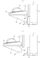
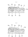
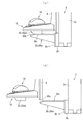
実施形態2のパチンコ機1は、実施形態1の支持部材35が受台15側に設けられているのに対し、その支持部材35を図15、図16(a),(b)に示したように外枠2の幕板2b側に設けたことを特徴とする。
実施形態2の支持部材35は、垂直断面T字状で、先端に端部に向かって下傾する案内テーパ部35bを設けたほぼ裏向きスキー板形状の支持板35cを上面に有するものであり、幕板2bの前面を構成する装飾樹脂パネル2b−1に一体成形されている。なお、支持部材35は、幕板2bと別体に例えば金属や合成樹脂で形成して該幕板2bに取り付けるようにしてもよい。
[Embodiment 2]
In the pachinko machine 1 according to the second embodiment, the support member 35 according to the first embodiment is provided on the cradle 15 side, whereas the support member 35 is shown in FIGS. 15, 16A, and 16B. As described above, the outer frame 2 is provided on the curtain plate 2b side.
The support member 35 according to the second embodiment has a T-shaped vertical cross section, and has a support plate 35c having a substantially back-facing ski plate shape on the upper surface provided with a guide taper portion 35b inclined downward toward the end at the tip. The decorative resin panel 2b-1 constituting the front surface of the curtain plate 2b is integrally formed. The support member 35 may be formed separately from the curtain plate 2b using, for example, metal or synthetic resin and attached to the curtain plate 2b.

実施形態2のパチンコ機1は以上のように構成されているため、前面部材4を閉じた図16(a)の状態では、支持部材35の支持板35cが受台15の下面を受けて実施形態1と同様に受台15の強度を高め得る。
また、図16(b)のように前面部材4を開いた状態から閉じる場合には、受台15の閉じ軌道が前面部材4の自重により支持部材35の支持板35cの上面より下がっていても、前記案内テーパ部35bに掬われるため、受台15の下面に支持部材35をスムーズに潜り込ませることができる。
Since the pachinko machine 1 according to the second embodiment is configured as described above, the support plate 35c of the support member 35 receives the lower surface of the cradle 15 in the state shown in FIG. Similar to the first embodiment, the strength of the cradle 15 can be increased.
Further, when the front member 4 is closed from the opened state as shown in FIG. 16B, even if the closing track of the cradle 15 is lowered from the upper surface of the support plate 35 c of the support member 35 due to the weight of the front member 4. The support member 35 can be smoothly inserted into the lower surface of the cradle 15 because the guide taper portion 35b is used.

[実施形態3]
実施形態1の支持部材35は受台15側に設けられており、一方、実施形態2の支持部材35は幕板2b側に設けられている。これに対し実施形態3の支持部材35は、図17(a),(b)に示したように、受台15側と幕板2b側の双方に設けられていて中間で分離可能に継ぎ合わさるようになっている。この場合、受台15側の支持部材35dと、幕板2b側の支持部材35eの基本構成は、それぞれ実施形態1、2とほぼ同じであるため説明を省略する。
[Embodiment 3]
The support member 35 of the first embodiment is provided on the cradle 15 side, while the support member 35 of the second embodiment is provided on the curtain plate 2b side. On the other hand, as shown in FIGS. 17A and 17B, the support member 35 according to the third embodiment is provided on both the cradle 15 side and the curtain plate 2b side so as to be separable in the middle. It is like that. In this case, the basic configuration of the support member 35d on the cradle 15 side and the support member 35e on the curtain plate 2b side is substantially the same as that of the first and second embodiments, and thus description thereof is omitted.

実施形態1についての説明で明らかなように支持部材35の全てを受台15に固定した場合には、前面部材4を単体で起立させる際に不安定になるおそれがあるが、実施形態3では、受台15側と幕板2b側で支持部材35d,35eを分割した結果、受台15側の支持部材35dを小さくすることができるため、受台15に支持部材35dを固定しても前面部材4の安定起立に与える影響を小さくすることができる。
また、実施形態2では、支持部材35の上面のレベルを前面部材4の下面のレベルとほぼ同じに設定する必要があり(そうでなければ前面部材4が支持部材35に衝突する。)、したがって、受台15の前面部材4上の配置が支持部材35の上面に接触する位置、つまり前面部材4の下辺ぎりぎりの位置に限定されることとなるが、実施形態3では、受台15と幕板2b側の支持部材35eとの間に受台15側の支持部材35dが介在することとなるため、受台15の前面部材4上の配置をある程度自由に設定することが可能になる。具体的には、受台15を高位置に配置し、その分、支持部材35dを長く(高さ)設計する、という具合である。なお、実施形態3では、受台15の底面部材15cに設けた調節手段17のためのカップ部15eを受台15側の支持部材35dとして利用することができる。
As is clear from the description of the first embodiment, when all of the support members 35 are fixed to the cradle 15, there is a risk that the front member 4 may become unstable when standing alone, but in the third embodiment, As a result of dividing the support members 35d and 35e on the cradle 15 side and the curtain plate 2b side, the support member 35d on the cradle 15 side can be made smaller. The influence on the stable standing of the member 4 can be reduced.
In the second embodiment, it is necessary to set the level of the upper surface of the support member 35 to be substantially the same as the level of the lower surface of the front member 4 (otherwise, the front member 4 collides with the support member 35). The position of the cradle 15 on the front member 4 is limited to the position where it contacts the upper surface of the support member 35, that is, the position just below the lower side of the front member 4. Since the support member 35d on the cradle 15 side is interposed between the support member 35e on the plate 2b side, the arrangement of the cradle 15 on the front member 4 can be freely set to some extent. Specifically, the cradle 15 is arranged at a high position, and the support member 35d is designed to be long (height) accordingly. In the third embodiment, the cup portion 15e for the adjusting means 17 provided on the bottom surface member 15c of the cradle 15 can be used as the support member 35d on the cradle 15 side.

上記の実施形態1〜3は、次の技術的思想1〜4を含む。
[技術的思想1]
四角い環状枠の下辺の前面に幕板を設けてなる外枠と、
該外枠の前面に片開きの扉状に開閉可能なように装着され閉じた状態で前記幕板の上に位置する前面部材と、
該前面部材の前面下方位置に設けられた遊技操作用のハンドルと、
前記前面部材の前面であって前記ハンドルの下側に遊技者側に向けて突設した受台と、を備えた遊技機であって、
前記幕板と前記受台とを棚受け状の支持部材で分離可能な状態に連繋させることにより、前記受台に加わる下向きの外力を前記幕板に分散させ得るようにしたことを特徴とする遊技機。
Embodiments 1 to 3 described above include the following technical ideas 1 to 4.
[Technical Thought 1]
An outer frame having a curtain plate on the front side of the lower side of the square annular frame;
A front member that is mounted on the front surface of the outer frame so as to be openable and closable in the form of a single-open door and is positioned on the curtain plate in a closed state;
A handle for game operation provided at a lower front position of the front member;
A gaming machine comprising: a front surface of the front member; and a cradle projecting toward the player side below the handle;
The curtain plate and the cradle are connected to each other in a separable state by a shelf-supporting support member so that downward external force applied to the cradle can be distributed to the curtain plate. Gaming machine.

[技術的思想2]
前記支持部材は、前記受台側に設けられていることを特徴とする技術的思想1記載の遊技機。
[Technical Thought 2]
The gaming machine according to the technical idea 1, wherein the support member is provided on the cradle side.

[技術的思想3]
前記支持部材は、前記幕板側に設けられていることを特徴とする技術的思想1記載の遊技機。
[Technical Thought 3]
The gaming machine according to the technical idea 1, wherein the support member is provided on the curtain side.

[技術的思想4]
前記支持部材は、前記受台側と前記幕板側の双方に設けられていて中間で分離可能に継ぎ合わさるものであることを特徴とする技術的思想1記載の遊技機。
[Technical Thought 4]
2. The gaming machine according to the technical idea 1, wherein the support member is provided on both the cradle side and the curtain side and is separably joined in the middle.

以上、本発明を実施形態1〜3について説明したが、もちろん本発明は上記実施形態に限定されるものではない。例えば、実施形態では、遊技機の一例として球皿6に投入した遊技球で遊技を行うパチンコ機を例示したが、遊技球を機内で循環させて持ち球データを加減算するいわゆる封入式のパチンコ機や、雀球式の遊技機などでも同様に適用できる。
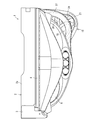
また、実施形態では障害部材37の大きさを図4のように平面視で受台15の輪郭より小さくしたが、障害部材37の大きさを図18の変形例に示したように平面視で受台15の輪郭程度に拡張し、そうすることでより受台15の保護効果を高めるようにしてもよい。
As mentioned above, although this invention was demonstrated about Embodiment 1-3, this invention is not limited to the said embodiment of course. For example, in the embodiment, as an example of a gaming machine, a pachinko machine that plays a game with game balls thrown into the ball tray 6 is illustrated, but a so-called encapsulated pachinko machine that adds and subtracts ball data by circulating the game balls in the machine. It can also be applied to sparrow ball type game machines.
Further, in the embodiment, the size of the obstacle member 37 is made smaller than the outline of the cradle 15 in plan view as shown in FIG. 4, but the size of the obstacle member 37 is shown in plan view as shown in the modification of FIG. You may make it extend to the outline of the receiving stand 15, and may make it raise the protection effect of the receiving stand 15 by doing so.

1 …パチンコ機(遊技機)
2 …外枠
4 …前面部材
6 …球皿
15 …受台
16 …ハンドル
37 …障害部材
38 …貫通部
1 ... Pachinko machine (game machine)
2 ... outer frame 4 ... front member 6 ... ball tray 15 ... cradle 16 ... handle 37 ... obstacle member 38 ... penetrating part

Claims (1)

遊技球が流下可能な遊技領域を備えた遊技機において、
前記遊技領域に遊技球を発射するために遊技者によって操作されるハンドル部と、
前記ハンドル部の上方に設けられ、該ハンドル部に向けて手を振り下ろす動作を困難にし得る位置に突出し且つ俯瞰方向からの該ハンドル部の視認を可能にする視認領域が形成された突出部と
有することを特徴とする遊技機。
In a gaming machine with a gaming area where game balls can flow down,
A handle portion operated by a player to launch a game ball into the game area;
A protruding portion provided above the handle portion, protruding to a position where it is difficult to swing down the hand toward the handle portion, and formed with a visual recognition region that allows the handle portion to be viewed from an overhead direction. and,
Gaming machine characterized in that it comprises a.
JP2013238283A 2013-11-18 2013-11-18 Game machine Active JP6263794B2 (en)

Priority Applications (1)

Application Number Priority Date Filing Date Title
JP2013238283A JP6263794B2 (en) 2013-11-18 2013-11-18 Game machine

Applications Claiming Priority (1)

Application Number Priority Date Filing Date Title
JP2013238283A JP6263794B2 (en) 2013-11-18 2013-11-18 Game machine

Related Child Applications (1)

Application Number Title Priority Date Filing Date
JP2017217090A Division JP6465526B2 (en) 2017-11-10 2017-11-10 Game machine

Publications (3)

Publication Number Publication Date
JP2015097593A JP2015097593A (en) 2015-05-28
JP2015097593A5 JP2015097593A5 (en) 2017-08-10
JP6263794B2 true JP6263794B2 (en) 2018-01-24

Family

ID=53374656

Family Applications (1)

Application Number Title Priority Date Filing Date
JP2013238283A Active JP6263794B2 (en) 2013-11-18 2013-11-18 Game machine

Country Status (1)

Country Link
JP (1) JP6263794B2 (en)

Cited By (1)

* Cited by examiner, † Cited by third party
Publication number Priority date Publication date Assignee Title
JP2018027344A (en) * 2017-11-10 2018-02-22 株式会社大一商会 Game machine

Family Cites Families (3)

* Cited by examiner, † Cited by third party
Publication number Priority date Publication date Assignee Title
JP4253879B2 (en) * 1998-11-06 2009-04-15 豊丸産業株式会社 Pachinko machine
JP2002177491A (en) * 2000-12-11 2002-06-25 Fuji Shoji:Kk Pachinko game machine
JP5819055B2 (en) * 2010-11-18 2015-11-18 京楽産業.株式会社 Pachinko machine

Cited By (1)

* Cited by examiner, † Cited by third party
Publication number Priority date Publication date Assignee Title
JP2018027344A (en) * 2017-11-10 2018-02-22 株式会社大一商会 Game machine

Also Published As

Publication number Publication date
JP2015097593A (en) 2015-05-28

Similar Documents

Publication Publication Date Title
JP2019058420A (en) Game machine
JP6263794B2 (en) Game machine
JP6485869B2 (en) Game machine
JP6465526B2 (en) Game machine
JP5465406B2 (en) Bullet ball machine
JP2015084887A (en) Game machine
JP5927406B2 (en) Bullet ball machine
JP5178415B2 (en) Bullet ball machine
JP6505156B2 (en) Gaming machine
JP6337263B2 (en) Game machine
JP5178416B2 (en) Bullet ball machine
JP2016093629A (en) Pinball game machine
JP6095448B2 (en) Game machine
JP6143811B2 (en) Game machine
JPH0331337Y2 (en)
JP6120643B2 (en) Game machine
JP6116322B2 (en) Game machine
JP6647510B2 (en) Gaming machine
JP2019058446A (en) Game machine
JP4742069B2 (en) Impeller of bullet ball machine
JP2019150652A (en) Game machine
JP2009089882A (en) Game machine
JP2016055020A (en) Game machine
JP2017012361A (en) Game machine
JP4187716B2 (en) Pachinko machine

Legal Events

Date Code Title Description
A621 Written request for application examination

Free format text: JAPANESE INTERMEDIATE CODE: A621

Effective date: 20161118

A521 Written amendment

Free format text: JAPANESE INTERMEDIATE CODE: A523

Effective date: 20170628

A131 Notification of reasons for refusal

Free format text: JAPANESE INTERMEDIATE CODE: A131

Effective date: 20170824

A977 Report on retrieval

Free format text: JAPANESE INTERMEDIATE CODE: A971007

Effective date: 20170823

A521 Written amendment

Free format text: JAPANESE INTERMEDIATE CODE: A523

Effective date: 20171018

TRDD Decision of grant or rejection written
A01 Written decision to grant a patent or to grant a registration (utility model)

Free format text: JAPANESE INTERMEDIATE CODE: A01

Effective date: 20171031

A61 First payment of annual fees (during grant procedure)

Free format text: JAPANESE INTERMEDIATE CODE: A61

Effective date: 20171130

R150 Certificate of patent or registration of utility model

Ref document number: 6263794

Country of ref document: JP

Free format text: JAPANESE INTERMEDIATE CODE: R150

R250 Receipt of annual fees

Free format text: JAPANESE INTERMEDIATE CODE: R250