JP2005296432A - Controller for game machine and game machine - Google Patents
Controller for game machine and game machine Download PDFInfo
- Publication number
- JP2005296432A JP2005296432A JP2004118802A JP2004118802A JP2005296432A JP 2005296432 A JP2005296432 A JP 2005296432A JP 2004118802 A JP2004118802 A JP 2004118802A JP 2004118802 A JP2004118802 A JP 2004118802A JP 2005296432 A JP2005296432 A JP 2005296432A
- Authority
- JP
- Japan
- Prior art keywords
- switch
- contact
- metal plate
- game machine
- end portion
- Prior art date
- Legal status (The legal status is an assumption and is not a legal conclusion. Google has not performed a legal analysis and makes no representation as to the accuracy of the status listed.)
- Pending
Links
Images
Classifications
-
- A—HUMAN NECESSITIES
- A63—SPORTS; GAMES; AMUSEMENTS
- A63F—CARD, BOARD, OR ROULETTE GAMES; INDOOR GAMES USING SMALL MOVING PLAYING BODIES; VIDEO GAMES; GAMES NOT OTHERWISE PROVIDED FOR
- A63F13/00—Video games, i.e. games using an electronically generated display having two or more dimensions
- A63F13/90—Constructional details or arrangements of video game devices not provided for in groups A63F13/20 or A63F13/25, e.g. housing, wiring, connections or cabinets
-
- A—HUMAN NECESSITIES
- A63—SPORTS; GAMES; AMUSEMENTS
- A63F—CARD, BOARD, OR ROULETTE GAMES; INDOOR GAMES USING SMALL MOVING PLAYING BODIES; VIDEO GAMES; GAMES NOT OTHERWISE PROVIDED FOR
- A63F13/00—Video games, i.e. games using an electronically generated display having two or more dimensions
- A63F13/20—Input arrangements for video game devices
- A63F13/24—Constructional details thereof, e.g. game controllers with detachable joystick handles
- A63F13/245—Constructional details thereof, e.g. game controllers with detachable joystick handles specially adapted to a particular type of game, e.g. steering wheels
-
- A—HUMAN NECESSITIES
- A63—SPORTS; GAMES; AMUSEMENTS
- A63F—CARD, BOARD, OR ROULETTE GAMES; INDOOR GAMES USING SMALL MOVING PLAYING BODIES; VIDEO GAMES; GAMES NOT OTHERWISE PROVIDED FOR
- A63F13/00—Video games, i.e. games using an electronically generated display having two or more dimensions
- A63F13/20—Input arrangements for video game devices
- A63F13/21—Input arrangements for video game devices characterised by their sensors, purposes or types
- A63F13/215—Input arrangements for video game devices characterised by their sensors, purposes or types comprising means for detecting acoustic signals, e.g. using a microphone
-
- A—HUMAN NECESSITIES
- A63—SPORTS; GAMES; AMUSEMENTS
- A63F—CARD, BOARD, OR ROULETTE GAMES; INDOOR GAMES USING SMALL MOVING PLAYING BODIES; VIDEO GAMES; GAMES NOT OTHERWISE PROVIDED FOR
- A63F13/00—Video games, i.e. games using an electronically generated display having two or more dimensions
- A63F13/40—Processing input control signals of video game devices, e.g. signals generated by the player or derived from the environment
- A63F13/42—Processing input control signals of video game devices, e.g. signals generated by the player or derived from the environment by mapping the input signals into game commands, e.g. mapping the displacement of a stylus on a touch screen to the steering angle of a virtual vehicle
- A63F13/424—Processing input control signals of video game devices, e.g. signals generated by the player or derived from the environment by mapping the input signals into game commands, e.g. mapping the displacement of a stylus on a touch screen to the steering angle of a virtual vehicle involving acoustic input signals, e.g. by using the results of pitch or rhythm extraction or voice recognition
-
- A—HUMAN NECESSITIES
- A63—SPORTS; GAMES; AMUSEMENTS
- A63F—CARD, BOARD, OR ROULETTE GAMES; INDOOR GAMES USING SMALL MOVING PLAYING BODIES; VIDEO GAMES; GAMES NOT OTHERWISE PROVIDED FOR
- A63F13/00—Video games, i.e. games using an electronically generated display having two or more dimensions
- A63F13/50—Controlling the output signals based on the game progress
- A63F13/54—Controlling the output signals based on the game progress involving acoustic signals, e.g. for simulating revolutions per minute [RPM] dependent engine sounds in a driving game or reverberation against a virtual wall
-
- A—HUMAN NECESSITIES
- A63—SPORTS; GAMES; AMUSEMENTS
- A63F—CARD, BOARD, OR ROULETTE GAMES; INDOOR GAMES USING SMALL MOVING PLAYING BODIES; VIDEO GAMES; GAMES NOT OTHERWISE PROVIDED FOR
- A63F13/00—Video games, i.e. games using an electronically generated display having two or more dimensions
- A63F13/55—Controlling game characters or game objects based on the game progress
- A63F13/57—Simulating properties, behaviour or motion of objects in the game world, e.g. computing tyre load in a car race game
-
- A—HUMAN NECESSITIES
- A63—SPORTS; GAMES; AMUSEMENTS
- A63F—CARD, BOARD, OR ROULETTE GAMES; INDOOR GAMES USING SMALL MOVING PLAYING BODIES; VIDEO GAMES; GAMES NOT OTHERWISE PROVIDED FOR
- A63F13/00—Video games, i.e. games using an electronically generated display having two or more dimensions
- A63F13/80—Special adaptations for executing a specific game genre or game mode
- A63F13/803—Driving vehicles or craft, e.g. cars, airplanes, ships, robots or tanks
-
- A—HUMAN NECESSITIES
- A63—SPORTS; GAMES; AMUSEMENTS
- A63F—CARD, BOARD, OR ROULETTE GAMES; INDOOR GAMES USING SMALL MOVING PLAYING BODIES; VIDEO GAMES; GAMES NOT OTHERWISE PROVIDED FOR
- A63F2300/00—Features of games using an electronically generated display having two or more dimensions, e.g. on a television screen, showing representations related to the game
- A63F2300/10—Features of games using an electronically generated display having two or more dimensions, e.g. on a television screen, showing representations related to the game characterized by input arrangements for converting player-generated signals into game device control signals
- A63F2300/1043—Features of games using an electronically generated display having two or more dimensions, e.g. on a television screen, showing representations related to the game characterized by input arrangements for converting player-generated signals into game device control signals being characterized by constructional details
-
- A—HUMAN NECESSITIES
- A63—SPORTS; GAMES; AMUSEMENTS
- A63F—CARD, BOARD, OR ROULETTE GAMES; INDOOR GAMES USING SMALL MOVING PLAYING BODIES; VIDEO GAMES; GAMES NOT OTHERWISE PROVIDED FOR
- A63F2300/00—Features of games using an electronically generated display having two or more dimensions, e.g. on a television screen, showing representations related to the game
- A63F2300/10—Features of games using an electronically generated display having two or more dimensions, e.g. on a television screen, showing representations related to the game characterized by input arrangements for converting player-generated signals into game device control signals
- A63F2300/1062—Features of games using an electronically generated display having two or more dimensions, e.g. on a television screen, showing representations related to the game characterized by input arrangements for converting player-generated signals into game device control signals being specially adapted to a type of game, e.g. steering wheel
-
- A—HUMAN NECESSITIES
- A63—SPORTS; GAMES; AMUSEMENTS
- A63F—CARD, BOARD, OR ROULETTE GAMES; INDOOR GAMES USING SMALL MOVING PLAYING BODIES; VIDEO GAMES; GAMES NOT OTHERWISE PROVIDED FOR
- A63F2300/00—Features of games using an electronically generated display having two or more dimensions, e.g. on a television screen, showing representations related to the game
- A63F2300/10—Features of games using an electronically generated display having two or more dimensions, e.g. on a television screen, showing representations related to the game characterized by input arrangements for converting player-generated signals into game device control signals
- A63F2300/1081—Input via voice recognition
-
- A—HUMAN NECESSITIES
- A63—SPORTS; GAMES; AMUSEMENTS
- A63F—CARD, BOARD, OR ROULETTE GAMES; INDOOR GAMES USING SMALL MOVING PLAYING BODIES; VIDEO GAMES; GAMES NOT OTHERWISE PROVIDED FOR
- A63F2300/00—Features of games using an electronically generated display having two or more dimensions, e.g. on a television screen, showing representations related to the game
- A63F2300/60—Methods for processing data by generating or executing the game program
- A63F2300/6063—Methods for processing data by generating or executing the game program for sound processing
- A63F2300/6072—Methods for processing data by generating or executing the game program for sound processing of an input signal, e.g. pitch and rhythm extraction, voice recognition
-
- A—HUMAN NECESSITIES
- A63—SPORTS; GAMES; AMUSEMENTS
- A63F—CARD, BOARD, OR ROULETTE GAMES; INDOOR GAMES USING SMALL MOVING PLAYING BODIES; VIDEO GAMES; GAMES NOT OTHERWISE PROVIDED FOR
- A63F2300/00—Features of games using an electronically generated display having two or more dimensions, e.g. on a television screen, showing representations related to the game
- A63F2300/60—Methods for processing data by generating or executing the game program
- A63F2300/64—Methods for processing data by generating or executing the game program for computing dynamical parameters of game objects, e.g. motion determination or computation of frictional forces for a virtual car
-
- A—HUMAN NECESSITIES
- A63—SPORTS; GAMES; AMUSEMENTS
- A63F—CARD, BOARD, OR ROULETTE GAMES; INDOOR GAMES USING SMALL MOVING PLAYING BODIES; VIDEO GAMES; GAMES NOT OTHERWISE PROVIDED FOR
- A63F2300/00—Features of games using an electronically generated display having two or more dimensions, e.g. on a television screen, showing representations related to the game
- A63F2300/80—Features of games using an electronically generated display having two or more dimensions, e.g. on a television screen, showing representations related to the game specially adapted for executing a specific type of game
- A63F2300/8017—Driving on land or water; Flying
Landscapes
- Engineering & Computer Science (AREA)
- Multimedia (AREA)
- Human Computer Interaction (AREA)
- Physics & Mathematics (AREA)
- Acoustics & Sound (AREA)
- Theoretical Computer Science (AREA)
- Switches With Compound Operations (AREA)
- Position Input By Displaying (AREA)
Abstract
Description
本発明は、操作レバーを有するゲーム機用コントローラ及びその関連技術に関する。 The present invention relates to a game machine controller having an operation lever and related technology.
特許文献1には、鉄道シミュレートゲームを行うための家庭用テレビゲーム機に接続して使用するゲーム機用コントローラが開示されている。このゲーム機用コントローラには、マスターコントロールレバーが、鉛直面内で回動可能なように取り付けられるとともに、ブレーキレバーが、水平面内で回動可能なように取り付けられる。 Patent Document 1 discloses a game machine controller that is used by being connected to a home video game machine for performing a railway simulation game. A master control lever is attached to the game machine controller so as to be rotatable in a vertical plane, and a brake lever is attached so as to be rotatable in a horizontal plane.
マスターコントロールレバーを操作することで、テレビ画面中の電車のスピードを段階的にコントロールできる。また、ブレーキレバーを操作することで、テレビ画面中の電車に対して、段階的にブレーキをかけることができる。 By operating the master control lever, you can control the speed of the train on the TV screen step by step. In addition, by operating the brake lever, it is possible to brake the train on the TV screen in stages.
このゲーム機用コントローラの内部には、マスターコントロールレバー及びブレーキレバーのそれぞれに対して、レバーの操作に応じて切り替わるロータリスイッチが設けられている。 Inside the game machine controller, a rotary switch is provided for each of the master control lever and the brake lever, which switches according to the operation of the lever.
しかしながら、レバーの操作に応じて切り替わるスイッチとしてロータリスイッチを採用している。従って、レバー側の接点が、基板上を摺り動くことになるため、耐久性及び信頼性が低くなるという問題点がある。 However, a rotary switch is employed as a switch that switches according to the operation of the lever. Therefore, since the contact on the lever side slides on the substrate, there is a problem that durability and reliability are lowered.
本発明は、耐久性及び信頼性を高めることができるゲーム機用コントローラ及びその関連技術を提供することを目的とする。 An object of this invention is to provide the controller for game machines which can improve durability and reliability, and its related technique.
本発明の第1の形態によると、ゲーム機用コントローラは、軸線のまわりに回転可能な軸部を有するレバーと、前記軸線のまわりに、前記軸部とともに回転する回転体と、前記軸部の軸線方向に垂直な方向に配置されるスイッチと、を備え、前記回転体には、凸部が形成され、前記スイッチは、第1の金属プレートの先端部及び第2の金属プレートの先端部を接点とし、かつ、前記第1の金属プレートの基端部と前記第2の金属プレートの基端部とを電気的に絶縁した状態で固定することにより形成され、前記スイッチの前記第1の金属プレートの前記先端部が、前記凸部に接触したときにのみ、前記スイッチの接点同士が接触するように、前記スイッチが配置される。 According to the first aspect of the present invention, the game machine controller includes a lever having a shaft portion rotatable around an axis, a rotating body that rotates with the shaft portion around the axis, and the shaft portion. A switch disposed in a direction perpendicular to the axial direction, and the rotating body has a convex portion, and the switch includes a tip portion of the first metal plate and a tip portion of the second metal plate. The first metal of the switch is formed by fixing the first metal plate and the base end of the second metal plate in an electrically insulated state as a contact point. The switch is arranged so that the contacts of the switch come into contact only when the tip of the plate comes into contact with the convex part.
この構成によれば、第1の金属プレート及び第2の金属プレートにより構成されるスイッチを、レバーの軸部とともに回転する凸部に接触させて、スイッチの接点同士を接触させている。従って、レバーの回転にともなうスイッチのオン/オフにより、レバーの操作状態を検知できる。このように、レバーの回転により基板を摺ることなく、レバーの操作状態を検知できるため、ロータリスイッチを用いる場合と比較して、耐久性及び信頼性を向上できる。 According to this structure, the switch comprised by the 1st metal plate and the 2nd metal plate is made to contact the convex part which rotates with the axial part of a lever, and the contact of switches is made to contact. Therefore, the operation state of the lever can be detected by turning the switch on / off as the lever rotates. As described above, since the operation state of the lever can be detected without sliding the substrate due to the rotation of the lever, durability and reliability can be improved as compared with the case where the rotary switch is used.
上記ゲーム機用コントローラにおいて、前記スイッチの前記第1の金属プレートの前記先端部には、接点の裏側に、前記凸部と接触する接触部が取り付けられ、前記スイッチの前記接触部が、前記凸部に接触したときにのみ、前記スイッチの接点同士が接触するように、前記スイッチが配置され、前記凸部は、その角部が曲面となるように、前記回転体に突出して形成される。この構成によれば、スイッチのオン/オフを滑らかに行うことができる。 In the game machine controller, a contact portion that contacts the convex portion is attached to the tip portion of the first metal plate of the switch on the back side of the contact, and the contact portion of the switch is the convex portion. The switch is disposed so that the contact points of the switch come into contact with each other only when contacting the part, and the convex part is formed to protrude from the rotating body so that the corner part is a curved surface. According to this configuration, the switch can be turned on / off smoothly.
本発明の第2の形態によると、ゲーム機用コントローラは、軸線のまわりに回転可能な軸部を有するレバーと、前記軸線のまわりに、前記軸部とともに回転する回転体と、前記軸部の軸線方向に垂直な方向に配置されるスイッチと、を備え、前記回転体には、前記軸部の回転方向の幅が所定の幅であり、基準面からの高さが所定の高さである凸部が形成され、前記スイッチは、第1の金属プレートの先端部及び第2の金属プレートの先端部を接点とし、かつ、前記第1の金属プレートの基端部と前記第2の金属プレートの基端部とを電気的に絶縁した状態で固定することにより形成され、前記凸部の前記所定の高さは、前記スイッチの接点間の間隔より所定距離高い。 According to the second aspect of the present invention, the game machine controller includes a lever having a shaft portion rotatable around an axis, a rotating body that rotates together with the shaft portion around the axis, and the shaft portion. A switch disposed in a direction perpendicular to the axial direction, and the rotating body has a predetermined width in the rotating direction of the shaft portion, and a predetermined height from the reference plane A convex part is formed, and the switch has a tip end part of the first metal plate and a tip part of the second metal plate as a contact, and a base end part of the first metal plate and the second metal plate The base end portion of the projection is fixed in an electrically insulated state, and the predetermined height of the convex portion is a predetermined distance higher than the interval between the contact points of the switch.
この構成によれば、凸部の所定の高さは、スイッチの接点間の間隔より所定距離高いので、第1の金属プレート及び第2の金属プレートにより構成されるスイッチを、レバーの軸部とともに回転する凸部に接触させることにより、スイッチの接点同士を接触させることができる。従って、レバーの回転にともなうスイッチのオン/オフにより、レバーの操作状態を検知できる。このように、レバーの回転により基板を摺ることなく、レバーの操作状態を検知できるため、ロータリスイッチを用いる場合と比較して、耐久性及び信頼性を向上できる。また、凸部の所定の高さは、スイッチの接点間の間隔より所定距離高いので、軸部にがたつきが生じた場合でも、確実にスイッチの接点同士を接触させることができる。 According to this configuration, the predetermined height of the convex portion is higher than the distance between the contact points of the switch by a predetermined distance. Therefore, the switch constituted by the first metal plate and the second metal plate is connected with the shaft portion of the lever. The contact points of the switches can be brought into contact with each other by contacting the rotating convex portions. Therefore, the operation state of the lever can be detected by turning the switch on / off as the lever rotates. As described above, since the operation state of the lever can be detected without sliding the substrate due to the rotation of the lever, durability and reliability can be improved as compared with the case where the rotary switch is used. Further, since the predetermined height of the convex portion is higher than the distance between the contact points of the switch by a predetermined distance, the contact points of the switch can be reliably brought into contact with each other even when the shaft portion is rattled.
上記ゲーム機用コントローラにおいて、前記スイッチの前記第1の金属プレートの前記先端部には、接点の裏側に、前記凸部と接触する接触部が取り付けられ、前記凸部は、その角部が曲面となるように、前記回転体に突出して形成される。この構成によれば、スイッチのオン/オフを滑らかに行うことができる。 In the game machine controller, a contact portion that comes into contact with the convex portion is attached to the tip of the first metal plate of the switch on the back side of the contact, and the convex portion has a curved surface at a corner. It is formed so as to protrude from the rotating body. According to this configuration, the switch can be turned on / off smoothly.
上記ゲーム機用コントローラは、ゲームプログラムに従って、ビデオ信号およびオーディオ信号を生成するプロセッサをさらに備えることができる。この構成によれば、プロセッサが、ゲーム機用コントローラに内蔵されているため、ゲーム機用コントローラとゲーム機本体とが別体となっている場合と比較して、コストの削減とユーザの利便性の向上を図ることができる。 The game machine controller may further include a processor that generates a video signal and an audio signal in accordance with a game program. According to this configuration, since the processor is built in the game machine controller, cost reduction and user convenience can be achieved compared to the case where the game machine controller and the game machine body are separate. Can be improved.
上記ゲーム機用コントローラは、プレイヤの音声を入力するマイクをさらに備えることもできる。この構成によれば、マイク入力に応じた処理を実行できるので、ゲーム内容をより充実させることができる。 The game machine controller may further include a microphone for inputting a player's voice. According to this configuration, since the process according to the microphone input can be executed, the game content can be further enhanced.
上記ゲーム機用コントローラにおいて、スイッチを複数設け、これに対応して、回転体に複数の凸部を設けることもできる。この構成によれば、レバーの操作状態をより詳細に検知できる。 In the game machine controller, a plurality of switches may be provided, and a plurality of convex portions may be provided on the rotating body corresponding to the switches. According to this configuration, the operation state of the lever can be detected in more detail.
本発明の第3の形態によると、ゲーム機は、走行中の列車の運転席からの景色をテレビジョンモニタに表示するゲーム機であって、ゲームプログラムに従って、前記テレビジョンモニタに出力するビデオ信号およびオーディオ信号を生成するプロセッサと、回動可能に取り付けられたレバーと、プレイヤにより押下され、所定の処理を前記プロセッサに実行させるスイッチと、を備え、前記プロセッサは、前記レバーの操作に応じて出力される信号に応じたビデオ信号を生成する。このゲーム機は、プレイヤの音声を入力するマイクをさらに備えることができる。 According to a third aspect of the present invention, the game machine is a game machine that displays a scenery from a driver's seat of a running train on a television monitor, and a video signal output to the television monitor according to a game program. And a processor that generates an audio signal, a lever that is pivotally attached, and a switch that is pressed by a player to cause the processor to execute a predetermined process, and the processor responds to an operation of the lever. A video signal corresponding to the output signal is generated. The game machine can further include a microphone for inputting the voice of the player.
以下、本発明の実施の形態について、図面を参照しながら説明する。なお、各図面において、同一の部分については、同一の参照符号を付している。 Hereinafter, embodiments of the present invention will be described with reference to the drawings. In each drawing, the same reference numerals are given to the same portions.
図1は、本発明の実施の形態におけるゲームシステムの全体構成を示す図である。図1に示すように、このゲームシステムは、ゲーム機1及びテレビジョンモニタ100を含む。このゲーム機1は、テレビジョンモニタ100に、列車の運転席からの景色やレール等の画像を映し出して、鉄道シミュレートゲームを行うものである。後で詳しく説明するが、本実施の形態では、ゲーム機1が、ゲーム機用コントローラを兼ねている。
FIG. 1 is a diagram showing an overall configuration of a game system according to an embodiment of the present invention. As shown in FIG. 1, the game system includes a game machine 1 and a
さて、テレビジョンモニタ100の前面にはスクリーン103が設けられ、スクリーン103の下部にAV端子105が設けられる。そして、ゲーム機1のAV端子326(後述)とテレビジョンモニタ100のAV端子105とが、AVケーブル110により接続される。また、ゲーム機1には、ACアダプタ120により、直流電源電圧が与えられる。ただし、ACアダプタ120に代えて、電池(図示せず)により、直流電源電圧を与えることもできる。
Now, a
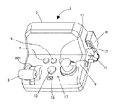
図2は、図1のゲーム機1の外観斜視図である。図2に示すように、このゲーム機1のハウジング2の上面左側寄りには、T字状のマスターコントロールレバー(以下、「マスコンレバー」と呼ぶ。)3が、鉛直面内で回動可能なように設けられる。ハウジング2の上面右側寄りには、ブレーキレバー5が、水平面内で回動可能なように設けられる。
FIG. 2 is an external perspective view of the game machine 1 of FIG. As shown in FIG. 2, a T-shaped master control lever (hereinafter referred to as “mass control lever”) 3 is rotatable in the vertical plane on the left side of the upper surface of the
また、ハウジング2の上面中央付近には、ライトスイッチ7、ワイパースイッチ9、ドアスイッチ11、警笛スイッチ13、電源スイッチ15、及び、システムのリセットを行うためのリセットスイッチ17が設けられる。さらに、ハウジング2の左側面には、マイクホルダ23が設けられ、このマイクホルダ23に、マイク19が保持される。マイク19には、マイクスイッチ21が設けられる。
Near the center of the upper surface of the
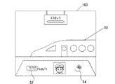
図3は、図1のスクリーン103に表示される発車画面の例示図である。図3に示すように、電源スイッチ15をオンにすると、ゲーム機1によって、スクリーン103に、発車画面が表示される。この発車画面は、列車画像50、速度表示部52、及び、マイク画像54を含む。速度表示部52には、列車の速度が表示される。マイク画像54は、マイク19のマイクスイッチ21を押下して、音声を入力するように、プレイヤに指示するものである。プレイヤが、マイクスイッチ21を押下して、マイク19から音声を入力し、さらに、マスコンレバー3を手前に引き寄せると、列車画像50が動き出す。つまり、列車が発車する。
FIG. 3 is a view showing an example of a departure screen displayed on the
なお、マイク画像54が表示される前は、同じ位置にドア画像(図示せず)が表示される。このドア画像は、プレイヤに、ドアスイッチ11を押下して、列車画像50のドアを閉じるように指示するものである。プレイヤが、ドアスイッチ11を押下することで、列車画像50のドアが閉まる。
Before the
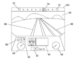
図4は、図1のスクリーン103に表示される走行画面の例示図である。図4に示すように、この走行画面は、走行中の列車の運転席から見た景色を表している。つまり、走行画面には、運転席から見た景色65やレール画像66,68が含まれる。また、走行画面には、運転席内部の、点灯指示部60、マイク入力指示部62、速度表示部52、メッセージ表示部64、推進力メータ56、及び制動メータ58が含まれる。さらに、走行画面の上端左側には、出発点オブジェクト70が表示され、上端右側には、終点オブジェクト72が表示され、それらの間には、走行位置指示オブジェクト74が表示される。
FIG. 4 is a view showing an example of a traveling screen displayed on the
点灯指示部60の色の変化は、プレイヤに、ライトの点灯を指示する。プレイヤが、ライトスイッチ7を押下すると、ライトにより前方が照らされたような画像が表示される。マイク入力指示部62の色の変化は、プレイヤに、音声の入力を指示する。プレイヤが、マイクスイッチ21を押下して、マイク19から音声を入力すると、テレビジョンモニタ100のスピーカ(図示せず)から、入力された音声が出力される。プレイヤが警笛スイッチ13を押下すると、テレビジョンモニタ100のスピーカ(図示せず)から、警笛音が出力される。
The change in the color of the
メッセージ表示部64には、プレイヤに対して様々なメッセージが表示される。例えば、ワイパーを動かして下さい、等のメッセージが表示される。プレイヤが、ワイパースイッチ9を押下すると、ワイパーが動いている画像が表示される。
In the
図2に戻って、マスコンレバー3は、列車の速度を変えるためのものであり、本実施の形態では、三段階に設定される。第一段階(一番奥にマスコンレバー3が位置する場合)は、推進力が「0」、第二段階(第一段階から一段手前にマスコンレバー3を引き寄せた状態)は、推進力が「1」、第三段階(第二段階から一段手前にマスコンレバー3を引き寄せた状態)は推進力が「2」である。推進力が「0」ということは、列車に推進力が働かないという意味である。推進力は、「1」より「2」のほうが大きい。プレイヤは、マスコンレバー3を操作して列車のスピードを調整できる。列車のスピードが上昇すると、景色65の移り変わりが速くなり、スピードが下降すると、景色65の移り変わりが遅くなる。図4の推進力メータ56は、マスコンレバー3の位置に応じて変化する。つまり、推進力に応じてメータの振れが変化する。
Returning to FIG. 2, the
ブレーキレバー5は、列車にブレーキをかけるためのものであり、本実施の形態では、三段階に設定される。第一段階(一番奥にブレーキレバー5が位置する場合)は、制動力が「0」、第二段階(第一段階から一段手前にブレーキレバー5を回転させた状態)は、推進力が「1」、第三段階(第二段階から一段手前にブレーキレバー5を回転させた状態)は制動力が「2」である。制動力が「0」ということは、列車に制動力が働かないという意味である。制動力は、「1」より「2」のほうが大きい。プレイヤは、ブレーキレバー5を操作して列車にブレーキをかけることができる。列車にブレーキをかけると、列車のスピードが下降して、それに応じた景色65が表示される。図4の制動力メータ58は、ブレーキレバー5の位置に応じて変化する。つまり、制動力に応じてメータの振れが変化する。
The brake lever 5 is for braking the train, and is set in three stages in the present embodiment. In the first stage (when the brake lever 5 is located at the back), the braking force is “0”, and in the second stage (the state in which the brake lever 5 is rotated one stage before the first stage), the propulsive force is “1”, the third stage (the state in which the brake lever 5 is rotated one stage before the second stage) has a braking force of “2”. A braking force of “0” means that no braking force is applied to the train. The braking force is larger at “2” than “1”. The player can brake the train by operating the brake lever 5. When the train is braked, the speed of the train decreases and a
走行画面の始点オブジェクト70は、列車の出発点を示し、終点オブジェクト72は、終点を示している。走行位置指示オブジェクト74は、現在の列車の位置を示すものである。なお、走行画面中、複線の一方がレール66であり、他方がレール68である。
The
図5は、図2のマスコンレバー3及びその周辺部材の分解斜視図である。図5に示すように、マスコンレバー3の基部221の両側面中央部には、軸28が形成される。マスコンレバー3は、例えば、ポリカーボネートで形成される。支持部材220の左側面には、開口224が形成され、支持部材220の内側から、開口224に、カラー200が挿入される。支持部材210の側面には、開口226が形成され、支持部材210の内側から、開口226に、カラー202が挿入される。支持部材220,210は、例えば、ABS(アクリロニトリルブタジエンスチレン)により形成され、カラー200,202は、例えば、ポリアセタールにより形成される。
FIG. 5 is an exploded perspective view of the
マスコンレバー3の一方の軸208は、開口224に取り付けられたカラー200の孔に回動可能に挿入され、他方の軸208は、開口226に取り付けられたカラー202の孔に回動可能に挿入される。また、支持部材210は、支持部材220の底部に固定される。以上のようにして、マスコンレバー3は、鉛直面内で、回動可能となる。なお、カラー200,202は、樹脂同士(ここでは、ポリカーボネートとABS)が摺りあうことによる樹脂の磨耗を防止するための部材である。このため、カラー200,202は、自己潤滑性を有する素材で形成されている。
One
支持部材220の底部には、上側に突き出るようにストッパ222が形成される。この機能は後で説明する。支持部材210の内側の側面には、ホルダ212,214及びボス216,218が形成され、これらにより、支持部材210にリーフスイッチ206,204が取り付けられる。この点を詳しく説明する。
A
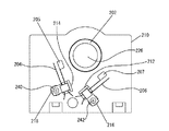
図6は、図5の2つのリーフスイッチ204,206の支持部材210への取り付け状態の説明図である。図6に示すように、リーフスイッチ204,206は、それぞれ、ホルダ214,212に保持される。そして、リーフスイッチ204の基部を挟むように、ビス240をボス218にねじ込んで、リーフスイッチ204を固定する。同様に、リーフスイッチ206の基部を挟むように、ビス242をボス216にねじ込んで、リーフスイッチ206を固定する。
FIG. 6 is an explanatory diagram of a state in which the two
図7は、図2のマスコンレバー3の回転角度と、リーフスイッチ204,206のオン/オフ状態と、の関係図である。図7に示すように、マスコンレバー3が、領域r1の範囲内(15度の範囲内)のときは、2つのリーフスイッチ204,206はオフになっている。マスコンレバー3が、領域r2の範囲内(50度の範囲内)のときは、リーフスイッチ204がオンする。マスコンレバー3が、領域r4の範囲内(25度の範囲内)のときは、リーフスイッチ206がオンする。従って、マスコンレバー3が、領域r3の範囲内(20度の範囲内)のときは、2つのリーフスイッチ204,206がオンすることになる。
FIG. 7 is a relationship diagram between the rotation angle of the
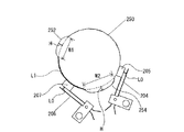
図8は、図2のマスコンレバー3が図7の領域r1の範囲内にあるときのリーフスイッチ204,206の状態を示す図である。図8に示すように、マスコンレバー3の基部221の右側面(図5の状態において)の中央部には、円柱状部(「回転体」と呼ぶこともある。)250が形成され、この円柱状部250の軸線に一致するように軸208が形成される。円柱状部250の円柱面(「基準面」と呼ぶこともある。)には、軸線方向に垂直な方向に、凸部252及び凸部254が形成される。凸部252,254が形成された円柱状部250は、マスコンレバー3の回転にともなって、軸208とともに回転する。
FIG. 8 is a diagram showing the state of the leaf switches 204 and 206 when the
マスコンレバー3が領域r1に位置する場合は、リーフスイッチ204,206の接触部205,207は、円柱状部250の円柱面に接しており、リーフスイッチ204,206はオフの状態である。なお、図8は、マスコンレバー3の第一段階の状態(推進力「0」)を示している。ここで、図5のストッパ222が、マスコンレバー3の基部221に形成されたエッジ部255に突き当たるので、これ以上時計回りに回転させることはできない。
When the
図9は、図2のマスコンレバー3が図7の領域(r2−r3)の範囲内にあるときのリーフスイッチ204,206の状態を示す図である。図9に示すように、マスコンレバー3が領域(r2−r3)に位置する場合は、リーフスイッチ204の接触部205が、凸部254に押されて、リーフスイッチ204の接点同士が接触してオンになる。一方、リーフスイッチ206の接触部207は、円柱状部250の円柱面に接しており、リーフスイッチ206はオフの状態である。なお、図9は、マスコンレバー3の第二段階の状態(推進力「1」)を示している。
FIG. 9 is a diagram showing the state of the leaf switches 204 and 206 when the
図10は、図2のマスコンレバー3が図7の領域r3の範囲内にあるときのリーフスイッチ204,206の状態を示す図である。図10に示すように、マスコンレバー3が領域r3に位置する場合は、リーフスイッチ204の接触部205が、凸部254に押されて、リーフスイッチ204の接点同士が接触してオンになる。同時に、リーフスイッチ206の接触部207が、凸部252に押されて、リーフスイッチ206の接点同士が接触してオンになる。なお、図10は、マスコンレバー3の第三段階の状態(推進力「2」)を示している。このように、リーフスイッチ204,206の双方がオンのときは、リーフスイッチ206を優先させる。
FIG. 10 is a diagram showing the state of the leaf switches 204 and 206 when the
図11は、図2のマスコンレバー3が図7の領域(r4−r3)の範囲内にあるときのリーフスイッチ204,206の状態を示す図である。図11に示すように、マスコンレバー3が領域(r4−r3)に位置する場合は、リーフスイッチ206の接触部207が、凸部252に押されて、リーフスイッチ206の接点同士が接触してオンになる。一方、リーフスイッチ204の接触部205は、円柱状部250の円柱面に接しており、リーフスイッチ204はオフの状態である。なお、図11は、マスコンレバー3の第三段階の状態(推進力「2」)を示している。ここで、図5のストッパ222が、マスコンレバー3の基部221に形成されたエッジ部253に突き当たるので、これ以上反時計回りに回転させることはできない。
FIG. 11 is a diagram showing the state of the leaf switches 204 and 206 when the
図12は、図8〜図11のマスコンレバー3の基部221に形成された円柱状部250の説明図である。図12に示すように、リーフスイッチ204の接点同士の間隔L0より、凸部254の高さHを高くしている。同様に、リーフスイッチ206の接点同士の間隔L0より、凸部252の高さHを高くしている。このようにすることで、リーフスイッチ204,206を確実にオンさせることができる。高さHを、間隔L0より、どのくらい高くするかについては、例えば、経験的に定めることができる。この場合、リーフスイッチ204,206がオンになった後、元に戻らなくなるほど、高さHを高くするのは好ましくない。
FIG. 12 is an explanatory diagram of the
また、凸部252の幅W1及びエッジ253の位置を調整することで、図7の領域r4の範囲を調整できる。凸部254の幅W2を調整することで、図7の領域r2の範囲を調整できる。凸部252と凸部254との間の距離L1を調整することで、図7の領域r3の範囲を調整できる。円柱状部250のエッジ255の位置及び凸部254の幅W2により、図7の領域r1の範囲を調整できる。
Further, by adjusting the width W1 of the
さて、図5〜図12を用いて、マスコンレバー3について説明してきたが、ブレーキレバー5も同様の機構により、2つのリーフスイッチ340,342(後述)のオン/オフを制御して、三段階の設定を実現している。
Although the
図13は、図2のゲーム機1の電気的構成を示す図である。図14(a)は、図13のマスコンスイッチユニット308の回路図、図14(b)は、図13のブレーキスイッチユニット310の回路図、図14(c)は、図13のスイッチユニット312の回路図、である。図15は、図13のマイクユニット314の回路図である。
FIG. 13 is a diagram showing an electrical configuration of the game machine 1 of FIG. 14A is a circuit diagram of the mass
図13に示すように、ゲーム機1は、高速プロセッサ300、ROM302、バス304、マスコンスイッチユニット308、ブレーキスイッチユニット310、スイッチユニット312、マイクユニット314、スイッチ316、音声ミキシング回路318、及び、AV端子326を含む。AV端子326は、オーディオ端子320,322及びビデオ端子324を含む。
As shown in FIG. 13, the game machine 1 includes a high-
高速プロセッサ300は、図示しないが、演算プロセサ,グラフィックプロセッサ,サウンドプロセッサおよびDMAプロセッサ等の各種プロセッサを含むとともに、アナログ信号を取り込むときに用いられるA/Dコンバータや、スイッチ操作信号のような入力信号を受けかつ出力信号を外部機器に与える入出力制御回路を含む。
Although not shown, the high-
高速プロセッサ300には、図示しないが内部メモリが設けられ、この内部メモリは、ROMまたはRAM(SRAMおよび/またはDRAM)を含む。RAMは一時メモリ、ワーキングメモリ、カウンタ、レジスタ領域(テンポラリデータ領域)およびフラグ領域として利用される。なお、高速プロセッサ300にはROM302がバス304を通して接続される。このROM302にゲームプログラムや画像データ等が格納される。
Although not shown, the high-
高速プロセッサ300は、ROM302に格納されたゲームプログラムに従って、演算、グラフィック処理、サウンド処理等を実行し、ビデオ信号VDおよびオーディオ信号AL,ARを生成する。ビデオ信号VDはゲーム画面(図3、図4参照)を表示するための画像信号であり、オーディオ信号AL,ARはゲーム音楽や効果音の信号であり、したがって、テレビジョンモニタ100のスクリーン103上にゲーム画面が表示され、必要なサウンド(効果音、ゲーム音楽)がそれのスピーカ(図示せず)から出力される。
The
図14(a)に示すように、マスコンスイッチユニット308は、リーフスイッチ204及び206を含み、それぞれの一方の接点には、電源電圧Vccが与えられる。リーフスイッチ204及び206の他方の接点は、それぞれ、高速プロセッサ300の入出力ポートIO0及びIO1に接続される。従って、リーフスイッチ204及び206のオン/オフ信号は、上記の入出力制御回路を介して、上記の演算プロセッサに与えられ、応じた処理が実行される。
As shown in FIG. 14A, the mass
つまり、リーフスイッチ204がオンのときは、入出力ポートIO0がハイレベルになり、リーフスイッチ206がオンのときは、入出力ポートIO1がハイレベルになる。高速プロセッサ300は、入出力ポートIO0及びIO1の値により、リーフスイッチ204及び206のオン/オフを判断して、対応する推進力に応じたビデオ信号VDを生成する。
That is, when the
図14(b)に示すように、ブレーキスイッチユニット310は、リーフスイッチ340及び342を含み、それぞれの一方の接点には、電源電圧Vccが与えられる。リーフスイッチ340及び342の他方の接点は、それぞれ、高速プロセッサ300の入出力ポートIO2及びIO3に接続される。従って、リーフスイッチ340及び342のオン/オフ信号は、上記の入出力制御回路を介して、上記の演算プロセッサに与えられ、応じた処理が実行される。
As shown in FIG. 14B, the
つまり、リーフスイッチ340がオンのときは、入出力ポートIO2がハイレベルになり、リーフスイッチ342がオンのときは、入出力ポートIO3がハイレベルになる。高速プロセッサ300は、入出力ポートIO2及びIO3の値により、リーフスイッチ340及び342のオン/オフを判断して、対応する制動力に応じたビデオ信号VDを生成する。
That is, when the
図14(c)に示すように、スイッチユニット312は、ライトスイッチ7、ワイパースイッチ9、ドアスイッチ11、及び警笛スイッチ13を含み、それぞれの一方の接点には、電源電圧Vccが与えられる。スイッチ7,9,11及び13の他方の接点は、それぞれ、高速プロセッサ300の入出力ポートIO4,IO5,IO6及びIO7に接続される。従って、スイッチ7,9,11及び13のオン/オフ信号は、上記の入出力制御回路を介して、上記の演算プロセッサに与えられ、応じた処理が実行される。
As shown in FIG. 14C, the
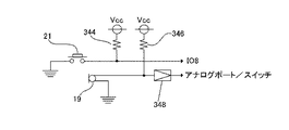
図15に示すように、マイクユニット314は、マイクスイッチ21、マイク19、抵抗素子344,346、及び音声増幅器348を含む。マイクスイッチ21の一方の接点は接地され、他方の接点は、抵抗素子344を介して電源Vccに接続されるとともに、高速プロセッサ300の入出力ポートIO8に接続される。従って、マイクスイッチ21のオン/オフ信号は、上記の入出力制御回路を介して、上記の演算プロセッサに与えられ、応じた処理が実行される。
As shown in FIG. 15, the
マイク19の一方の端子は接地され、他方の端子は、抵抗素子346を介して、電源Vccに接続されるとともに、音声増幅器348に接続される。図13に示すように、音声増幅器348の出力端子は、高速プロセッサ300のアナログポート及びスイッチ316に接続される。
One terminal of the
マイクスイッチ21が押下されると、入出力ポートIO8がローレベルになる。すると、高速プロセッサ300は、図13のスイッチ316をオンにする。従って、マイク19から入力され、音声増幅器348で増幅された音声信号は、高速プロセッサ300のアナログポートだけでなく、音声ミキシング回路318にも入力される。音声ミキシング回路318は、オーディオ信号AL,ARと、マイク21からの音声信号と、を合成して、オーディオ端子320,322に出力する。これにより、マイク19からの音声が、テレビジョンモニタ100のスピーカから出力される。なお、ビデオ信号は、ビデオ端子324に出力される。
When the
一方、マイクスイッチ21がオフの場合は、入出力ポートIO8がハイレベルになる。すると、高速プロセッサ300は、図13のスイッチ316をオフにする。従って、音声がマイク19から入力されても、音声ミキシング回路318には入力されないので、マイク19からの音声は、テレビジョンモニタ100のスピーカから出力されない。
On the other hand, when the
ここで、図3で説明したように、高速プロセッサ300は、マイクスイッチ21がオンであり(ポートIO8がローレベルの場合)、マイク19から音声が入力された場合であって(アナログポートに一定レベル以上の信号の入力があった場合)、マスコンスイッチユニット308のリーフスイッチ204及び206のいずれか、あるいは双方がオンの場合(ポートIO0及びIO1のいずれか、あるいは双方がハイレベルの場合)に、高速プロセッサ300は、列車画像50が動き出すビデオ信号VDを生成する。
Here, as described with reference to FIG. 3, the high-
さて、上記では、マスコンレバー3の操作を検知するために、リーフスイッチ204,206を使用した。他の例として、リーフスイッチ204,206の代わりに、ラバースイッチ400,402を用いることもできる。
In the above description, the leaf switches 204 and 206 are used to detect the operation of the
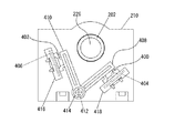
図16は、図2のマスコンレバー3の操作を検知するための他の機構の説明図である。図16に示すように、支持部材210の側面には、ホルダ416,418が形成される。そして、ホルダ416及び418には、それぞれ、接点が形成された基板406及び404が保持される。そして、基板406及び404には、それぞれ、ラバースイッチ402及び400が取り付けられる。
FIG. 16 is an explanatory diagram of another mechanism for detecting the operation of the
また、支持部材210の側面には、軸412が形成されていて、ロッド408及び410の基端部に設けられた孔に、軸412が挿入される。ロッド408及び410は、軸412の回りに回動可能である。なお、ビス414を用いて、ロッド408及び410が、軸412から抜けることを防止している。
In addition, a
図17は、図16の機構により、マスコンレバー3の操作を検知する場合の説明図である。図17に示すように、マスコンレバー3が領域r1の範囲では、ロッド408,410が、円柱状部250の円柱面に接しており、ラバースイッチ400,402は、オフになっている。マスコンレバー3が領域(r2−r3)の範囲では、凸部254により、ロッド410が押されて、ラバースイッチ402がオンする。一方、ロッド408は、円柱面に接しており、ラバースイッチ400はオフである。
FIG. 17 is an explanatory diagram when the operation of the
マスコンレバー3が領域r3の範囲では、凸部254により、ロッド410が押されて、ラバースイッチ402がオンするとともに、凸部252により、ロッド408が押されて、ラバースイッチ400がオンする。マスコンレバー3が領域(r4−r3)の範囲では、凸部252により、ロッド408が押されて、ラバースイッチ400がオンする。一方、ロッド410は、円柱面に接しており、ラバースイッチ402はオフである。
When the
ここで、一般に、ラバースイッチは、押下されたままの状態で長期間放置されると、もとの形状に回復できず、オン状態が維持されるという不都合も生じうる。しかし、リーフスイッチの場合は、このような不都合は発生せず、ラバースイッチを用いるよりも、リーフスイッチを用いるほうが好ましい。 Here, generally, if the rubber switch is left pressed for a long time, the rubber switch cannot be restored to its original shape, and there may be a disadvantage that the ON state is maintained. However, in the case of a leaf switch, such inconvenience does not occur, and it is preferable to use a leaf switch rather than a rubber switch.
なお、図16及び図17で説明した機構は、ブレーキレバー5にも同様に適用できる。 16 and 17 can be applied to the brake lever 5 in the same manner.
さて、以上のように、本実施の形態によれば、リーフスイッチ204,206の接触部205,207を、マスコンレバー3の軸208とともに回転する凸部254,252に接触させて、接点同士を接触させている。従って、マスコンレバー3の回転にともなうリーフスイッチ204,207のオン/オフにより、マスコンレバー3の操作状態を検知できる。このように、ロータリスイッチを用いることなく、マスコンレバー3の操作状態を検知しているため、ロータリスイッチを用いる場合と比較して、耐久性及び信頼性を向上できる。
As described above, according to the present embodiment, the
また、本実施の形態では、円柱状部250の凸部252,254の高さHは、リーフスイッチ206,204の接点間の間隔L0より高い。従って、軸208にがたつきが生じた場合でも、確実にリーフスイッチ206,204の接点同士を接触させることができる。
In the present embodiment, the height H of the
さらに、本実施の形態では、リーフスイッチ204,206の先端部には、接触部205,207が取り付けられ、さらに、円柱状部250の凸部254,252は、その角部が曲面となるように形成されている。このため、リーフスイッチのオン/オフを滑らかに行うことができる。
Furthermore, in the present embodiment, the
さらに、本実施の形態では、ゲーム機用コントローラに、プロセッサ300を内蔵して、ゲーム機1を構成している。従って、ゲーム機用コントローラとゲーム機本体とが別体となっている場合と比較して、コストの削減とユーザの利便性の向上を図ることができる。
Further, in the present embodiment, the game machine 1 is configured by incorporating the
さらに、本実施の形態では、ゲーム機1は、プレイヤの音声を入力するマイク19を備えている。このため、高速プロセッサ300は、マイク入力に応じた処理を実行できるので、ゲーム内容をより充実させることができる。
Furthermore, in the present embodiment, the game machine 1 includes a
なお、本発明は、上記の実施の形態に限られるものではなく、その要旨を逸脱しない範囲で種々の態様において実施することが可能であり、例えば、以下のような変形も可能である。 The present invention is not limited to the above-described embodiment, and can be implemented in various modes without departing from the gist thereof. For example, the following modifications are possible.
(1)上記では、2つのリーフスイッチ204及び206、ならびに、これに対応して2つの凸部252,254を設けた。ただし、これらの数はこれに限定されない。リーフスイッチを3個以上設け、これに対応して、3個以上の凸部を形成することもできる。リーフスイッチ及び凸部の数を増やせば、マスコンレバー3の操作状態をより詳細に検知できる。また、リーフスイッチ1個に、凸部1個とすることもできる。この点、ラバースイッチを用いる場合も同様である。
(1) In the above description, the two
(2)上記では、リーフスイッチ206の先端部の向きと(図8で言えば、時計回りの回転方向)、リーフスイッチ204の先端部の向きと(図8で言えば、反時計回りの回転方向)、が逆であったが、同じ向きなるように、リーフスイッチ204,206を取り付けることもできる。 (2) In the above, the direction of the tip of the leaf switch 206 (clockwise rotation direction in FIG. 8) and the direction of the tip of the leaf switch 204 (counterclockwise rotation in FIG. 8) Although the direction) is reversed, the leaf switches 204 and 206 can be mounted so that they are in the same direction.
(3)上記では、リーフスイッチ204,206がオフのときは、その接触部205,207が、円柱状部250の円柱面に接するように、リーフスイッチ204,206を配置した。ただし、必ずしも接している必要はなく、離れていてもよい。
(3) In the above description, when the leaf switches 204 and 206 are off, the leaf switches 204 and 206 are arranged so that the
(4)図16及び図17の例では、ロッド408とロッド410との回転軸を共通の軸412としたが、それぞれに対して軸を設けてもよい。また、ロッド408の先端部の向きと(図17で言えば、時計回りの回転方向)、ロッド410の先端部の向きと(図17で言えば、反時計回りの回転方向)、が逆であったが、同じ向きなるように、ロッド408,410を取り付けることもできる。この場合は、ロッド408及びロッド410のそれぞれに対して回転軸を設ける。
(4) In the example of FIGS. 16 and 17, the rotation axis of the
(5)上記のリーフスイッチやラバースイッチに代えて、マイクロスイッチを使用することもできる。 (5) Instead of the leaf switch or rubber switch, a micro switch can be used.
(6)図13の高速プロセッサ300として、任意の種類のプロセッサを使用できるが、本件出願人が既に特許出願している高速プロセッサを用いることが好ましい。この高速プロセッサは、例えば、特開平10−307790号公報およびこれに対応するアメリカ特許第6,070,205号に詳細に開示されている。
(6) Although any type of processor can be used as the high-
1…ゲーム機、2…ハウジング、3…マスターコントロールレバー、5…ブレーキレバー、7…ライトスイッチ、9…ワイパースイッチ、11…ドアスイッチ、13…警笛スイッチ、15…電源スイッチ、17…リセットスイッチ、19…マイク、21…マイクスイッチ、23…マイクホルダ、50…列車画像、52…速度表示部、54…マイク画像、56…推進力メータ、58…制動力メータ、60…点灯指示部、62…マイク入力指示部、64…メッセージ表示部、65…景色、66,68…レール、70…始点オブジェクト、72…終点オブジェクト、74…列車位置指示オブジェクト、100…テレビジョンモニタ、103…スクリーン、105,326…AV端子、110…AVケーブル、120…ACアダプタ、200,202…カラー、204,206,340,342…リーフスイッチ、205,207…接触部、208…軸、210,220…支持部材、212,214,416,418…ホルダ、216,218,412…ボス、221…基部、222…ストッパ、224,226…開口、240,242,414…ビス、300…高速プロセッサ、302…ROM、304…バス、308…マスコンスイッチユニット、310…ブレーキスイッチユニット、312…スイッチユニット、314…マイクユニット、316…スイッチ、318…音声ミキシング回路、320,322…オーディオ端子、324…ビデオ端子、348…音声増幅器、400,402…ラバースイッチ、404,406…基板、408,410…ロッド。
DESCRIPTION OF SYMBOLS 1 ... Game machine, 2 ... Housing, 3 ... Master control lever, 5 ... Brake lever, 7 ... Light switch, 9 ... Wiper switch, 11 ... Door switch, 13 ... Horn switch, 15 ... Power switch, 17 ... Reset switch, DESCRIPTION OF
Claims (12)
前記軸線のまわりに、前記軸部とともに回転する回転体と、
前記軸部の軸線方向に垂直な方向に配置されるスイッチと、を備え、
前記回転体には、凸部が形成され、
前記スイッチは、第1の金属プレートの先端部及び第2の金属プレートの先端部を接点とし、かつ、前記第1の金属プレートの基端部と前記第2の金属プレートの基端部とを電気的に絶縁した状態で固定することにより形成され、
前記スイッチの前記第1の金属プレートの前記先端部が、前記凸部に接触したときにのみ、前記スイッチの接点同士が接触するように、前記スイッチが配置される、ゲーム機用コントローラ。 A lever having a shaft portion rotatable around an axis;
A rotating body that rotates with the shaft around the axis;
A switch disposed in a direction perpendicular to the axial direction of the shaft portion,
A convex part is formed on the rotating body,
The switch uses the distal end portion of the first metal plate and the distal end portion of the second metal plate as contacts, and connects the proximal end portion of the first metal plate and the proximal end portion of the second metal plate. Formed by fixing in an electrically insulated state,
The game machine controller, wherein the switch is arranged so that the contact points of the switch come into contact with each other only when the tip of the first metal plate of the switch contacts the convex part.
前記スイッチの前記接触部が、前記凸部に接触したときにのみ、前記スイッチの接点同士が接触するように、前記スイッチが配置され、
前記凸部は、その角部が曲面となるように、前記回転体に突出して形成される、請求項1記載のゲーム機用コントローラ。 The tip of the first metal plate of the switch is attached with a contact portion in contact with the convex portion on the back side of the contact,
The switch is arranged so that the contact points of the switch come into contact only when the contact part of the switch comes into contact with the convex part,
The game machine controller according to claim 1, wherein the convex portion is formed to project from the rotating body such that a corner portion thereof is a curved surface.
前記軸線のまわりに、前記軸部とともに回転する回転体と、
前記軸部の軸線方向に垂直な方向に配置されるスイッチと、を備え、
前記回転体には、前記軸部の回転方向の幅が所定の幅であり、基準面からの高さが所定の高さである凸部が形成され、
前記スイッチは、第1の金属プレートの先端部及び第2の金属プレートの先端部を接点とし、かつ、前記第1の金属プレートの基端部と前記第2の金属プレートの基端部とを電気的に絶縁した状態で固定することにより形成され、
前記凸部の前記所定の高さは、前記スイッチの接点間の間隔より所定距離高い、ゲーム機用コントローラ。 A lever having a shaft portion rotatable around an axis;
A rotating body that rotates with the shaft around the axis;
A switch disposed in a direction perpendicular to the axial direction of the shaft portion,
The rotating body is formed with a convex portion whose width in the rotation direction of the shaft portion is a predetermined width and whose height from the reference plane is a predetermined height,
The switch uses the distal end portion of the first metal plate and the distal end portion of the second metal plate as contacts, and connects the proximal end portion of the first metal plate and the proximal end portion of the second metal plate. Formed by fixing in an electrically insulated state,
The game machine controller, wherein the predetermined height of the convex portion is higher by a predetermined distance than an interval between contact points of the switch.
前記凸部は、その角部が曲面となるように、前記回転体に突出して形成される、請求項3記載のゲーム機用コントローラ。 The tip of the first metal plate of the switch is attached with a contact portion in contact with the convex portion on the back side of the contact,
The game machine controller according to claim 3, wherein the convex portion is formed to protrude from the rotating body such that a corner portion thereof is a curved surface.
前記軸線のまわりに、前記軸部とともに回転する回転体と、
前記軸部の軸線方向に垂直な方向に配置される複数のスイッチと、を備え、
前記回転体には、前記複数のスイッチに対応して、複数の凸部が形成され、
前記スイッチは、第1の金属プレートの先端部及び第2の金属プレートの先端部を接点とし、かつ、前記第1の金属プレートの基端部と前記第2の金属プレートの基端部とを電気的に絶縁した状態で固定することにより形成され、
前記スイッチの前記第1の金属プレートの前記先端部が、対応する前記凸部に接触したときにのみ、そのスイッチの接点同士が接触するように、前記スイッチが配置される、ゲーム機用コントローラ。 A lever having a shaft portion rotatable around an axis;
A rotating body that rotates with the shaft around the axis;
A plurality of switches arranged in a direction perpendicular to the axial direction of the shaft portion,
The rotating body has a plurality of convex portions corresponding to the plurality of switches,
The switch uses the distal end portion of the first metal plate and the distal end portion of the second metal plate as contacts, and connects the proximal end portion of the first metal plate and the proximal end portion of the second metal plate. Formed by fixing in an electrically insulated state,
A controller for a game machine, wherein the switch is arranged such that contact points of the switch come into contact only when the tip of the first metal plate of the switch comes into contact with the corresponding convex part.
前記スイッチの前記接触部が、対応する前記凸部に接触したときにのみ、そのスイッチの接点同士が接触するように、前記スイッチが配置され、
前記凸部は、その角部が曲面となるように、前記回転体に突出して形成される、請求項5記載のゲーム機用コントローラ。 At the tip of the first metal plate of the switch, a contact portion that contacts the corresponding convex portion is attached to the back side of the contact,
The switch is arranged so that the contact points of the switch come into contact only when the contact part of the switch comes into contact with the corresponding convex part,
The game machine controller according to claim 5, wherein the convex portion is formed to protrude from the rotating body such that a corner portion thereof is a curved surface.
前記軸線のまわりに、前記軸部とともに回転する回転体と、
前記軸部の軸線方向に垂直な方向に配置される複数のスイッチと、を備え、
前記回転体には、前記複数のスイッチと対応して、前記軸部の回転方向の幅が所定の幅であり、基準面からの高さが所定の高さである複数の凸部が形成され、
前記スイッチは、第1の金属プレートの先端部及び第2の金属プレートの先端部を接点とし、かつ、前記第1の金属プレートの基端部と前記第2の金属プレートの基端部とを電気的に絶縁した状態で固定することにより形成され、
前記凸部の前記所定の高さは、対応する前記スイッチの接点間の間隔より所定距離高い、ゲーム機用コントローラ。 A lever having a shaft portion rotatable around an axis;
A rotating body that rotates with the shaft around the axis;
A plurality of switches arranged in a direction perpendicular to the axial direction of the shaft portion,
Corresponding to the plurality of switches, the rotating body is formed with a plurality of convex portions having a predetermined width in the rotation direction of the shaft portion and a predetermined height from the reference plane. ,
The switch uses the distal end portion of the first metal plate and the distal end portion of the second metal plate as contacts, and connects the proximal end portion of the first metal plate and the proximal end portion of the second metal plate. Formed by fixing in an electrically insulated state,
The game machine controller, wherein the predetermined height of the convex portion is higher by a predetermined distance than an interval between corresponding contact points of the switch.
前記凸部は、その角部が曲面となるように、前記回転体に突出して形成される、請求項7記載のゲーム機用コントローラ。 The tip of the first metal plate of the switch is attached with a contact portion in contact with the convex portion on the back side of the contact,
The game machine controller according to claim 7, wherein the convex portion is formed to protrude from the rotating body such that a corner portion thereof is a curved surface.
ゲームプログラムに従って、前記テレビジョンモニタに出力するビデオ信号およびオーディオ信号を生成するプロセッサと、
回動可能に取り付けられたレバーと、
プレイヤにより押下され、所定の処理を前記プロセッサに実行させるスイッチと、を備え、
前記プロセッサは、前記レバーの操作に応じて出力される信号に応じたビデオ信号を生成する、ゲーム機。 A game machine that displays a view from the driver's seat of a running train on a television monitor,
A processor for generating a video signal and an audio signal to be output to the television monitor according to a game program;
A pivotally mounted lever;
A switch that is pressed by a player and causes the processor to execute a predetermined process;
The game machine, wherein the processor generates a video signal according to a signal output in response to an operation of the lever.
The game machine according to claim 11, further comprising a microphone for inputting a voice of the player.
Priority Applications (3)
| Application Number | Priority Date | Filing Date | Title |
|---|---|---|---|
| JP2004118802A JP2005296432A (en) | 2004-04-14 | 2004-04-14 | Controller for game machine and game machine |
| US11/104,881 US7235748B2 (en) | 2004-04-14 | 2005-04-13 | Video game controller and game apparatus |
| EP05008183A EP1586356A1 (en) | 2004-04-14 | 2005-04-14 | A video game controller and game apparatus |
Applications Claiming Priority (1)
| Application Number | Priority Date | Filing Date | Title |
|---|---|---|---|
| JP2004118802A JP2005296432A (en) | 2004-04-14 | 2004-04-14 | Controller for game machine and game machine |
Publications (2)
| Publication Number | Publication Date |
|---|---|
| JP2005296432A true JP2005296432A (en) | 2005-10-27 |
| JP2005296432A5 JP2005296432A5 (en) | 2007-06-07 |
Family
ID=34935175
Family Applications (1)
| Application Number | Title | Priority Date | Filing Date |
|---|---|---|---|
| JP2004118802A Pending JP2005296432A (en) | 2004-04-14 | 2004-04-14 | Controller for game machine and game machine |
Country Status (3)
| Country | Link |
|---|---|
| US (1) | US7235748B2 (en) |
| EP (1) | EP1586356A1 (en) |
| JP (1) | JP2005296432A (en) |
Cited By (6)
| Publication number | Priority date | Publication date | Assignee | Title |
|---|---|---|---|---|
| JP2008086348A (en) * | 2006-09-29 | 2008-04-17 | Taito Corp | Display change device and game machine |
| JP2010063555A (en) * | 2008-09-09 | 2010-03-25 | Daiichi Shokai Co Ltd | Pinball game machine |
| JP2010063554A (en) * | 2008-09-09 | 2010-03-25 | Daiichi Shokai Co Ltd | Pinball game machine |
| JP2010094465A (en) * | 2008-10-20 | 2010-04-30 | Daiichi Shokai Co Ltd | Pinball game machine |
| JP2017144122A (en) * | 2016-02-18 | 2017-08-24 | 株式会社タイトー | Input device |
| JP2017144119A (en) * | 2016-02-18 | 2017-08-24 | 株式会社タイトー | Input device |
Families Citing this family (24)
| Publication number | Priority date | Publication date | Assignee | Title |
|---|---|---|---|---|
| US7682237B2 (en) * | 2003-09-22 | 2010-03-23 | Ssd Company Limited | Music game with strike sounds changing in quality in the progress of music and entertainment music system |
| US8568213B2 (en) | 2005-11-04 | 2013-10-29 | Mattel, Inc. | Game unit with controller-determined characters |
| JP2013034714A (en) * | 2011-08-09 | 2013-02-21 | Universal Entertainment Corp | Game terminal and method of providing notification |
| CN103223867B (en) * | 2013-03-11 | 2016-01-27 | 中山市金龙游乐设备有限公司 | A kind of selector device for recreation automobile |
| CN104667525B (en) * | 2013-11-29 | 2020-08-04 | 艾朗博格发明有限公司 | Game controller |
| WO2015110553A1 (en) * | 2014-01-22 | 2015-07-30 | Ironburg Inventions | Games controller |
| WO2015118082A2 (en) | 2014-02-05 | 2015-08-13 | Ironburg Inventions | Controller for a games console, tool and a method therefor |
| ES2729270T3 (en) | 2015-01-09 | 2019-10-31 | Ironburg Inventions Ltd | Game Console Controller |
| ES2877632T3 (en) | 2015-09-23 | 2021-11-17 | Ironburg Inventions Ltd | Game controller |
| US10427036B2 (en) | 2015-09-24 | 2019-10-01 | Ironburg Inventions Limited | Games controller |
| US10940386B2 (en) | 2015-10-09 | 2021-03-09 | Ironburg Inventions Limited | Games controller |
| CN108472542B (en) | 2015-11-27 | 2021-07-06 | 铁堡发明有限公司 | Game controller and trigger therefor |
| US10118092B2 (en) * | 2016-05-03 | 2018-11-06 | Performance Designed Products Llc | Video gaming system and method of operation |
| WO2017192506A1 (en) | 2016-05-03 | 2017-11-09 | Performance Designed Products Llc | Video gaming system and method of operation |
| GB2566869A (en) | 2016-06-14 | 2019-03-27 | Ironburg Invent Ltd | Games controller |
| CN109803733A (en) | 2016-08-11 | 2019-05-24 | 铁堡发明有限公司 | For computer input device |
| US11013986B2 (en) | 2017-03-15 | 2021-05-25 | Ironburg Inventions Limited | Input apparatus for a games console |
| US11103775B2 (en) | 2017-06-12 | 2021-08-31 | Ironburg Inventions Limited | Input apparatus for a games console |
| USD881125S1 (en) | 2018-09-05 | 2020-04-14 | Ironburg Inventions Limited | Game controller motor set |
| USD889549S1 (en) | 2018-09-05 | 2020-07-07 | Ironburg Inventions Limited | Game controller |
| USD881283S1 (en) | 2018-09-05 | 2020-04-14 | Ironburg Inventions Limited | Game controller |
| USD889550S1 (en) | 2018-09-05 | 2020-07-07 | Ironburg Inventions Limited | Game controller |
| USD881282S1 (en) | 2018-09-05 | 2020-04-14 | Ironburg Inventions Limited | Game controller |
| USD983269S1 (en) | 2020-06-19 | 2023-04-11 | Ironburg Inventions Limited | Input apparatus for a games console |
Family Cites Families (28)
| Publication number | Priority date | Publication date | Assignee | Title |
|---|---|---|---|---|
| DE1219560B (en) | 1962-07-24 | 1966-06-23 | Rau Swf Autozubehoer | counter |
| DE1229623B (en) | 1963-09-04 | 1966-12-01 | Holzer Patent Ag | Drive for switching devices, in particular for program controls |
| US4052578A (en) * | 1976-01-06 | 1977-10-04 | Hoke William A | Multiple cam, multiple position switch control mechanism with joy-stick type operator operable in x-y planes |
| US4538035A (en) * | 1983-02-11 | 1985-08-27 | Pool Danny J | Joystick occlusion gate control for video games |
| US4479038A (en) * | 1983-02-11 | 1984-10-23 | Cal-Tron Corporation | Mode conditioned joystick control for video games |
| US4514600A (en) * | 1983-11-14 | 1985-04-30 | North American Philips Corporation | Video game hand controller |
| US4814556A (en) * | 1987-05-08 | 1989-03-21 | Emhart Industries, Inc. | Camstack and switch assembly and timer utilizing same |
| US4853502A (en) * | 1988-07-11 | 1989-08-01 | Fasco Controls Corporation | Combination brake and/or clutch pedal operated switch mechanism |
| JPH0350468U (en) | 1989-09-22 | 1991-05-16 | ||
| JP3228107B2 (en) * | 1995-12-28 | 2001-11-12 | 市光工業株式会社 | Switch device |
| US6259433B1 (en) * | 1996-05-14 | 2001-07-10 | Norman H. Meyers | Digital optical joystick with mechanically magnified resolution |
| US5799223A (en) * | 1996-05-31 | 1998-08-25 | Minolta Co., Ltd. | Camera in use of a film cartridge which contains a film wound around a winding shaft in a light-shielding condition |
| JPH10127946A (en) * | 1996-11-05 | 1998-05-19 | Konami Co Ltd | Operating lever device |
| TW448363B (en) | 1997-02-17 | 2001-08-01 | Ssd Co Ltd | High speed processor system with bus arbitration |
| JP3467382B2 (en) | 1997-05-06 | 2003-11-17 | 新世代株式会社 | High speed processor |
| JP2996930B2 (en) * | 1997-04-04 | 2000-01-11 | 三和電子株式会社 | Joystick controller |
| US5883690A (en) * | 1997-05-30 | 1999-03-16 | Z-Products | Joystick adapter for a directional keypad on a game controller |
| GB9904607D0 (en) * | 1999-03-01 | 1999-04-21 | Stedman Kenneth B | Wheel hub |
| JP2000331567A (en) * | 1999-05-24 | 2000-11-30 | Mikku Enterprise:Kk | Waterproof type lever switch |
| US6338485B1 (en) * | 2000-04-09 | 2002-01-15 | John D. Huettlinger | Strap device for use with a video game controller |
| US6459420B1 (en) * | 2000-06-26 | 2002-10-01 | Curtis James Harris | Ergonomical joystick design or attachment |
| US20020110246A1 (en) * | 2001-02-14 | 2002-08-15 | Jason Gosior | Wireless audio system |
| US20020128064A1 (en) * | 2001-03-06 | 2002-09-12 | Sobota John F. | Game controller |
| US6904823B2 (en) * | 2002-04-03 | 2005-06-14 | Immersion Corporation | Haptic shifting devices |
| US20030232648A1 (en) * | 2002-06-14 | 2003-12-18 | Prindle Joseph Charles | Videophone and videoconferencing apparatus and method for a video game console |
| JP2004171851A (en) * | 2002-11-19 | 2004-06-17 | Matsushita Electric Ind Co Ltd | Multidirectional operation switch |
| USD478590S1 (en) * | 2003-01-29 | 2003-08-19 | Intec, Inc. | Video game controller |
| US20050169252A1 (en) * | 2004-02-03 | 2005-08-04 | Andrew Riggs | Game controller including an integrated communicator |
-
2004
- 2004-04-14 JP JP2004118802A patent/JP2005296432A/en active Pending
-
2005
- 2005-04-13 US US11/104,881 patent/US7235748B2/en not_active Expired - Fee Related
- 2005-04-14 EP EP05008183A patent/EP1586356A1/en not_active Withdrawn
Cited By (7)
| Publication number | Priority date | Publication date | Assignee | Title |
|---|---|---|---|---|
| JP2008086348A (en) * | 2006-09-29 | 2008-04-17 | Taito Corp | Display change device and game machine |
| JP4526524B2 (en) * | 2006-09-29 | 2010-08-18 | 株式会社タイトー | Display change device and game machine |
| JP2010063555A (en) * | 2008-09-09 | 2010-03-25 | Daiichi Shokai Co Ltd | Pinball game machine |
| JP2010063554A (en) * | 2008-09-09 | 2010-03-25 | Daiichi Shokai Co Ltd | Pinball game machine |
| JP2010094465A (en) * | 2008-10-20 | 2010-04-30 | Daiichi Shokai Co Ltd | Pinball game machine |
| JP2017144122A (en) * | 2016-02-18 | 2017-08-24 | 株式会社タイトー | Input device |
| JP2017144119A (en) * | 2016-02-18 | 2017-08-24 | 株式会社タイトー | Input device |
Also Published As
| Publication number | Publication date |
|---|---|
| US20050230230A1 (en) | 2005-10-20 |
| US7235748B2 (en) | 2007-06-26 |
| EP1586356A1 (en) | 2005-10-19 |
Similar Documents
| Publication | Publication Date | Title |
|---|---|---|
| JP2005296432A (en) | Controller for game machine and game machine | |
| US8300504B2 (en) | Switch device, information processing device, and reproduction device | |
| US8149656B2 (en) | Switch device, information processing device, and reproduction device | |
| US20060095753A1 (en) | Information processing apparatus and boot control method | |
| JP6893561B2 (en) | Vibration control device | |
| CN102664000A (en) | Piano learning and playing auxiliary system | |
| JP2005296432A5 (en) | ||
| JP2007181569A (en) | Game device and its control method | |
| JPH1040067A (en) | Sound control system interlocking with operation of pointing device | |
| GB2464822A (en) | Movable stage video displays | |
| JPH08305531A (en) | Agent interface system for household appliance personal computer | |
| JP3396035B2 (en) | Image processing device | |
| JPH092168A (en) | On-vehicle display device | |
| TW575446B (en) | Recording medium, computer and method operating car images on a screen of the computer | |
| JP2006285434A (en) | Information display | |
| JP2003251070A (en) | Game device, control method for the game device and program | |
| US20100053077A1 (en) | Notebook computer with force feedback for gaming | |
| JP2014046894A (en) | On-vehicle electronic apparatus | |
| JP6858322B2 (en) | Electronics | |
| JP2013015627A (en) | Keyboard device | |
| JP3064790U (en) | Electronic equipment | |
| JP6830633B2 (en) | Electronics | |
| CN102023675A (en) | Video device | |
| JP2018040986A (en) | Electronic acoustic device and operation method for the same | |
| JP2000251461A5 (en) |
Legal Events
| Date | Code | Title | Description |
|---|---|---|---|
| A621 | Written request for application examination |
Free format text: JAPANESE INTERMEDIATE CODE: A621 Effective date: 20070412 |
|
| A521 | Request for written amendment filed |
Free format text: JAPANESE INTERMEDIATE CODE: A523 Effective date: 20070413 |
|
| A521 | Request for written amendment filed |
Free format text: JAPANESE INTERMEDIATE CODE: A523 Effective date: 20080218 |
|
| A131 | Notification of reasons for refusal |
Free format text: JAPANESE INTERMEDIATE CODE: A131 Effective date: 20090512 |
|
| A521 | Request for written amendment filed |
Free format text: JAPANESE INTERMEDIATE CODE: A523 Effective date: 20090623 |
|
| A02 | Decision of refusal |
Free format text: JAPANESE INTERMEDIATE CODE: A02 Effective date: 20090825 |

