JP2010057704A - Method for manufacturing needle body, needle body, and grinding blade - Google Patents
Method for manufacturing needle body, needle body, and grinding blade Download PDFInfo
- Publication number
- JP2010057704A JP2010057704A JP2008226784A JP2008226784A JP2010057704A JP 2010057704 A JP2010057704 A JP 2010057704A JP 2008226784 A JP2008226784 A JP 2008226784A JP 2008226784 A JP2008226784 A JP 2008226784A JP 2010057704 A JP2010057704 A JP 2010057704A
- Authority
- JP
- Japan
- Prior art keywords
- grinding blade
- needle
- inclined surface
- grinding
- groove
- Prior art date
- Legal status (The legal status is an assumption and is not a legal conclusion. Google has not performed a legal analysis and makes no representation as to the accuracy of the status listed.)
- Granted
Links
- 238000000227 grinding Methods 0.000 title claims abstract description 113
- 238000000034 method Methods 0.000 title claims abstract description 57
- 238000004519 manufacturing process Methods 0.000 title claims abstract description 35
- 239000000758 substrate Substances 0.000 claims description 17
- 238000000465 moulding Methods 0.000 claims description 9
- 238000005459 micromachining Methods 0.000 claims description 2
- 230000015572 biosynthetic process Effects 0.000 abstract description 5
- 239000000463 material Substances 0.000 description 42
- 239000000654 additive Substances 0.000 description 11
- 230000010076 replication Effects 0.000 description 11
- 230000000996 additive effect Effects 0.000 description 10
- 229940079593 drug Drugs 0.000 description 9
- PXHVJJICTQNCMI-UHFFFAOYSA-N Nickel Chemical compound [Ni] PXHVJJICTQNCMI-UHFFFAOYSA-N 0.000 description 8
- 239000003814 drug Substances 0.000 description 8
- 229910003460 diamond Inorganic materials 0.000 description 7
- 239000010432 diamond Substances 0.000 description 7
- 210000003491 skin Anatomy 0.000 description 7
- 238000001721 transfer moulding Methods 0.000 description 7
- 239000000919 ceramic Substances 0.000 description 6
- 238000011049 filling Methods 0.000 description 6
- 239000000560 biocompatible material Substances 0.000 description 5
- 239000012778 molding material Substances 0.000 description 5
- 229920005989 resin Polymers 0.000 description 5
- 239000011347 resin Substances 0.000 description 5
- 210000000434 stratum corneum Anatomy 0.000 description 5
- 229910052759 nickel Inorganic materials 0.000 description 4
- 229920000515 polycarbonate Polymers 0.000 description 4
- 239000004417 polycarbonate Substances 0.000 description 4
- 230000003746 surface roughness Effects 0.000 description 4
- 230000000694 effects Effects 0.000 description 3
- 238000007689 inspection Methods 0.000 description 3
- 238000005498 polishing Methods 0.000 description 3
- OWEGMIWEEQEYGQ-UHFFFAOYSA-N 100676-05-9 Natural products OC1C(O)C(O)C(CO)OC1OCC1C(O)C(O)C(O)C(OC2C(OC(O)C(O)C2O)CO)O1 OWEGMIWEEQEYGQ-UHFFFAOYSA-N 0.000 description 2
- 229920002101 Chitin Polymers 0.000 description 2
- 229920001661 Chitosan Polymers 0.000 description 2
- 229920002307 Dextran Polymers 0.000 description 2
- GUBGYTABKSRVRQ-PICCSMPSSA-N Maltose Natural products O[C@@H]1[C@@H](O)[C@H](O)[C@@H](CO)O[C@@H]1O[C@@H]1[C@@H](CO)OC(O)[C@H](O)[C@H]1O GUBGYTABKSRVRQ-PICCSMPSSA-N 0.000 description 2
- 238000010521 absorption reaction Methods 0.000 description 2
- 238000005266 casting Methods 0.000 description 2
- 230000007547 defect Effects 0.000 description 2
- 210000002615 epidermis Anatomy 0.000 description 2
- 239000010408 film Substances 0.000 description 2
- 238000001746 injection moulding Methods 0.000 description 2
- 238000003754 machining Methods 0.000 description 2
- 229920002529 medical grade silicone Polymers 0.000 description 2
- 230000003287 optical effect Effects 0.000 description 2
- 238000007747 plating Methods 0.000 description 2
- 229920000747 poly(lactic acid) Polymers 0.000 description 2
- 239000004626 polylactic acid Substances 0.000 description 2
- 239000000523 sample Substances 0.000 description 2
- 239000004065 semiconductor Substances 0.000 description 2
- 239000000243 solution Substances 0.000 description 2
- 239000000126 substance Substances 0.000 description 2
- 208000031872 Body Remains Diseases 0.000 description 1
- YCKRFDGAMUMZLT-UHFFFAOYSA-N Fluorine atom Chemical compound [F] YCKRFDGAMUMZLT-UHFFFAOYSA-N 0.000 description 1
- 229930182556 Polyacetal Natural products 0.000 description 1
- 239000006061 abrasive grain Substances 0.000 description 1
- NIXOWILDQLNWCW-UHFFFAOYSA-N acrylic acid group Chemical group C(C=C)(=O)O NIXOWILDQLNWCW-UHFFFAOYSA-N 0.000 description 1
- 230000002411 adverse Effects 0.000 description 1
- PNEYBMLMFCGWSK-UHFFFAOYSA-N aluminium oxide Inorganic materials [O-2].[O-2].[O-2].[Al+3].[Al+3] PNEYBMLMFCGWSK-UHFFFAOYSA-N 0.000 description 1
- 239000008280 blood Substances 0.000 description 1
- 210000004369 blood Anatomy 0.000 description 1
- 150000001720 carbohydrates Chemical class 0.000 description 1
- 238000004113 cell culture Methods 0.000 description 1
- 238000006243 chemical reaction Methods 0.000 description 1
- 238000005229 chemical vapour deposition Methods 0.000 description 1
- PMHQVHHXPFUNSP-UHFFFAOYSA-M copper(1+);methylsulfanylmethane;bromide Chemical compound Br[Cu].CSC PMHQVHHXPFUNSP-UHFFFAOYSA-M 0.000 description 1
- 239000002537 cosmetic Substances 0.000 description 1
- 238000005520 cutting process Methods 0.000 description 1
- 238000013500 data storage Methods 0.000 description 1
- 210000004207 dermis Anatomy 0.000 description 1
- 239000006185 dispersion Substances 0.000 description 1
- 238000009826 distribution Methods 0.000 description 1
- 238000007876 drug discovery Methods 0.000 description 1
- 238000004049 embossing Methods 0.000 description 1
- 238000001125 extrusion Methods 0.000 description 1
- 229910052731 fluorine Inorganic materials 0.000 description 1
- 239000011737 fluorine Substances 0.000 description 1
- 239000000446 fuel Substances 0.000 description 1
- 239000011521 glass Substances 0.000 description 1
- 230000009931 harmful effect Effects 0.000 description 1
- 239000012535 impurity Substances 0.000 description 1
- 229910010272 inorganic material Inorganic materials 0.000 description 1
- 239000011147 inorganic material Substances 0.000 description 1
- 238000002156 mixing Methods 0.000 description 1
- 210000005036 nerve Anatomy 0.000 description 1
- 239000011368 organic material Substances 0.000 description 1
- 239000003960 organic solvent Substances 0.000 description 1
- 239000002245 particle Substances 0.000 description 1
- 230000002093 peripheral effect Effects 0.000 description 1
- 229920006324 polyoxymethylene Polymers 0.000 description 1
- 238000003672 processing method Methods 0.000 description 1
- 238000000746 purification Methods 0.000 description 1
- 229910052710 silicon Inorganic materials 0.000 description 1
- 239000010703 silicon Substances 0.000 description 1
- 229920002050 silicone resin Polymers 0.000 description 1
- 238000003756 stirring Methods 0.000 description 1
- 239000010409 thin film Substances 0.000 description 1
- 238000005406 washing Methods 0.000 description 1
- XLYOFNOQVPJJNP-UHFFFAOYSA-N water Substances O XLYOFNOQVPJJNP-UHFFFAOYSA-N 0.000 description 1
Images


Classifications
-
- A—HUMAN NECESSITIES
- A61—MEDICAL OR VETERINARY SCIENCE; HYGIENE
- A61M—DEVICES FOR INTRODUCING MEDIA INTO, OR ONTO, THE BODY; DEVICES FOR TRANSDUCING BODY MEDIA OR FOR TAKING MEDIA FROM THE BODY; DEVICES FOR PRODUCING OR ENDING SLEEP OR STUPOR
- A61M37/00—Other apparatus for introducing media into the body; Percutany, i.e. introducing medicines into the body by diffusion through the skin
- A61M37/0015—Other apparatus for introducing media into the body; Percutany, i.e. introducing medicines into the body by diffusion through the skin by using microneedles
- A61M2037/0053—Methods for producing microneedles
Abstract
Description
本発明は、研削刃を用いた針状体製造方法および該針状体製造方法に適した研削刃に関する。 The present invention relates to a needle-shaped body manufacturing method using a grinding blade and a grinding blade suitable for the needle-shaped body manufacturing method.
皮膚上から薬剤を浸透させ体内に薬剤を投与する方法である経皮吸収法は、人体に痛みを与えることなく簡便に薬剤を投与することが出来る方法として用いられているが、薬剤の種類によっては経皮吸収法で投与が困難な薬剤が存在する。これらの薬剤を効率よく体内に吸収させる方法として、ミクロンオーダーの微細な針状体を用いて皮膚を穿孔し、皮膚内に直接薬剤を投与する方法が注目されている。この方法によれば、投薬用の特別な機器を用いることなく、簡便に薬剤を皮下投薬することが可能となる(特許文献1参照)。 The percutaneous absorption method, which is a method of infiltrating a drug from the skin and administering the drug into the body, is used as a method that can be easily administered without causing pain to the human body. There are drugs that are difficult to administer by transdermal absorption. As a method of efficiently absorbing these drugs into the body, a method of perforating the skin using micron-order fine needles and administering the drug directly into the skin has attracted attention. According to this method, it is possible to easily administer a drug subcutaneously without using a special medication device (see Patent Document 1).
この際に用いる微細な針状体の形状は、皮膚を穿孔するための十分な細さと先端角、および皮下に薬液を浸透させるための十分な長さを有していることが必要とされ、直径は数μmから数百μm、長さは皮膚の最外層である角質層を貫通し、かつ神経層へ到達しない長さ、具体的には数十μmから数百μm程度のものであることが望ましいとされている。 The shape of the fine needle-like body used at this time is required to have a sufficient fineness and tip angle for piercing the skin and a sufficient length for allowing the drug solution to penetrate subcutaneously, The diameter should be several μm to several hundred μm, and the length should be a length that penetrates the stratum corneum, which is the outermost layer of the skin, and does not reach the nerve layer, specifically several tens μm to several hundred μm. Is preferred.
より具体的には、最外皮層である角質層を貫通することが求められる。角質層の厚さは部位によっても若干異なるが、平均して20μm程度である。また、角質層の下にはおよそ200μmから350μm程度の厚さの表皮が存在し、さらにその下層には毛細血管が張りめぐる真皮層が存在する。このため、角質層を貫通させ薬液を浸透させるためには少なくとも20μm以上の針が必要となる。また、採血を目的とする針状体を製造する場合には、上記の皮膚の構成から少なくとも350μm以上の高さの針状体が必要となる。 More specifically, it is required to penetrate the stratum corneum that is the outermost skin layer. The thickness of the stratum corneum varies slightly depending on the site, but is about 20 μm on average. In addition, an epidermis having a thickness of about 200 μm to 350 μm exists under the stratum corneum, and further, a dermis layer in which capillaries are stretched exists under the epidermis. For this reason, in order to penetrate the stratum corneum and allow the chemical solution to penetrate, a needle of at least 20 μm or more is required. Further, when producing a needle-like body for the purpose of blood collection, a needle-like body having a height of at least 350 μm or more is required due to the above-described skin structure.
また、針状体を構成する材料としては、仮に破損した針状体が体内に残留した場合でも、人体に悪影響を及ぼしにくい材料であることが必要であり、この材料としては医療用シリコーンや、マルトース、ポリ乳酸、デキストラン、キチン、キトサン、ポリカーボネート等の生体適合樹脂が有望視されている(特許文献2参照)。 In addition, as a material constituting the needle-shaped body, even if a damaged needle-shaped body remains in the body, it is necessary to be a material that does not adversely affect the human body, such as medical silicone, Biocompatible resins such as maltose, polylactic acid, dextran, chitin, chitosan, and polycarbonate are considered promising (see Patent Document 2).
微細な針状体の製造方法の例として、研削加工技術を用いる手法が提案されている(特許文献3参照)。 As an example of a method for manufacturing a fine needle-like body, a method using a grinding technique has been proposed (see Patent Document 3).
また、医療用の生体適合性のある針状体の作製方法として、原版から複製版を起こし、その複製版を用いて転写成形を行う手法が提案されている(特許文献4参照)。
このような微細構造を低コストかつ大量に製造するためには、射出成形法、インプリント法、キャスティング法に代表される転写成形方法が有効であるが、いずれの方法においても成形を行うためには所望の形状を有する原版が必要である。
しかしながら、機械加工等を用いて原版を作製した場合、その加工面は大きな表面粗さを持つ。そのため、このような原版をもとに転写成形を行った場合、枠型と成形品が張り付く現象が発生するという問題がある。特に、強度面で比較的脆弱となる針状体先端部の領域では、枠型からの剥離時に先端部が欠損する現象が発生するという問題も生じる。
In order to produce such a fine structure at a low cost and in large quantities, a transfer molding method represented by an injection molding method, an imprinting method, and a casting method is effective. Requires an original having a desired shape.
However, when the original plate is produced by machining or the like, the processed surface has a large surface roughness. Therefore, when transfer molding is performed based on such an original plate, there is a problem that a phenomenon occurs in which the frame mold and the molded product stick. In particular, in the region of the tip of the needle-like body that is relatively fragile in terms of strength, there also arises a problem that a phenomenon that the tip is lost at the time of peeling from the frame mold occurs.
そこで、本発明は、上述の問題を解決するためになされたものであり、微細構造を有する針状体の加工時および転写成形時の欠損を抑制することが可能な針状体製造方法を提供することを目的とする。 Therefore, the present invention has been made to solve the above-described problems, and provides a method for manufacturing a needle-like body capable of suppressing defects during processing and transfer molding of a needle-like body having a fine structure. The purpose is to do.
請求項1に記載の本発明は、研削加工を用いて基板に第1の方向に沿って互いに平行な複数の第1の線状溝を形成する工程と、研削加工を用いて基板に第1の方向と交差する第2の方向に沿って互いに平行な複数の第2の線状溝を形成する工程と、を備え、前記研削加工に用いる研削刃の断面形状は、先端面と側面との間に傾斜面が形成された形状であり、前記傾斜面に段差段面を有する研削刃であることを特徴とする針状体製造方法である。 According to a first aspect of the present invention, there is provided a step of forming a plurality of first linear grooves parallel to each other along a first direction in the substrate using a grinding process, and a first step of forming the substrate on the substrate using a grinding process. Forming a plurality of second linear grooves parallel to each other along a second direction intersecting with the direction of the step, and the cross-sectional shape of the grinding blade used for the grinding is a tip surface and a side surface An acicular body manufacturing method characterized in that it is a grinding blade having a stepped surface on the inclined surface.
請求項2に記載の本発明は、請求項1に記載の針状体製造方法を用いて製造された針状体を原版とした複製版を形成し、該複製版を用いて転写加工成形を行うことを特徴とした針状体製造方法である。 According to a second aspect of the present invention, a replica plate is formed using the needle-shaped body manufactured by the method of manufacturing the needle-shaped body according to the first aspect as an original plate, and transfer processing molding is performed using the replica plate. It is a needle-shaped object manufacturing method characterized by performing.
請求項3に記載の本発明は、微細加工に用いる研削刃であって、研削刃の断面形状は、先端面と側面との間に傾斜面が形成された形状であり、前記傾斜面に段差段面を有することを特徴とする研削刃である。
The present invention according to
請求項4に記載の本発明は、請求項3に記載の研削刃であって、前記段差段面の前後で、傾斜面の傾斜角度が異なることを特徴とする研削刃である。
The present invention according to
請求項5に記載の本発明は、 傾斜面に段差段面を備え、該段差により先鋭部側の傾斜面と根元部側の傾斜面とが区別され、前記先鋭部側の傾斜面の傾斜角度と前記根元部側の傾斜面の傾斜角度とが異なることを特徴とした針状体である。 The present invention according to claim 5 is provided with a stepped surface on the inclined surface, and the inclined surface on the sharpened portion side and the inclined surface on the root portion side are distinguished by the step, and the inclination angle of the inclined surface on the sharpened portion side And the angle of inclination of the inclined surface on the base portion side is different.
本発明の針状体製造方法によれば、段差段面を備えた研削刃を用いることにより、多段構造の針状体が作製可能となる。 According to the needle-shaped body manufacturing method of the present invention, a needle-shaped body having a multi-stage structure can be manufactured by using a grinding blade having a stepped surface.
<研削刃>
以下、本発明の研削刃について、具体的に説明を行う。
<Grinding blade>
Hereinafter, the grinding blade of the present invention will be specifically described.
一般的に、研削加工は、高速で回転するスピンドルの先端に取り付けられた研削刃による精密機械加工であって、被加工基材に切溝を微細加工する。研削刃は、円盤状の支持体の外周部に形成される。研削刃の材質としては高い硬度を有することが望ましく、一般にダイヤモンドを用いることが多い。本発明においても、円盤状の支持体の外周部全面にダイヤモンドから成る研削刃が形成された、ダイヤモンドホイールを用いることが出来る。ダイヤモンドホイールは、半導体産業における基板の断裁工程で広く用いられており、安価で入手が容易な部材である。 Generally, grinding is precision machining with a grinding blade attached to the tip of a spindle that rotates at a high speed, and finely cuts a kerf on a workpiece substrate. A grinding blade is formed in the outer peripheral part of a disk shaped support body. As a material of the grinding blade, it is desirable to have a high hardness, and diamond is generally used in many cases. In the present invention, it is also possible to use a diamond wheel in which a grinding blade made of diamond is formed on the entire outer periphery of a disc-shaped support. Diamond wheels are widely used in the cutting process of substrates in the semiconductor industry, and are inexpensive and readily available members.
図1に研削刃先端の部分断面図を示す。図1(a)は、従来の研削刃の断面図であり、図1(b)は本発明の研削刃の断面図である。 FIG. 1 shows a partial cross-sectional view of the tip of the grinding blade. FIG. 1A is a cross-sectional view of a conventional grinding blade, and FIG. 1B is a cross-sectional view of the grinding blade of the present invention.
図1(a)に示すように、従来の研削刃10の断面形状は、研削刃側壁面4と研削刃先端面5が90°の角を成して交わり、直交頂点6を形成している。
このため、従来の研削刃を用いて研削加工を行っても、傾斜面を備えた構造体を形成できないことから、錐形状の針状体を形成することは出来ない。
As shown in FIG. 1A, the cross-sectional shape of the conventional grinding blade 10 is such that the grinding blade
For this reason, even if it grinds using the conventional grinding blade, since the structure provided with the inclined surface cannot be formed, the cone-shaped acicular body cannot be formed.
図1(b)に示すように、本発明の研削刃11の断面形状は、研削刃側壁面4と研削刃先端面5との間に傾斜面7を有し、傾斜面7に段差段面14を有する。また、段差断面14により、傾斜面7は斜面A12と斜面B13との範囲を区切る。
傾斜面を備えた研削刃を用いることにより、加工対象に傾斜面を形成することが出来ることから、錐形状の針状体を形成することが出来る。
また、本発明の研削刃は、傾斜面に段差段面を備えることから、特に、図4に示すような、多段の針状体を好適に形成することが出来る。多段の針状体形状は、転写成形時の欠損が発生しやすい針状体先端の近傍のみ接触面積を低減させた構造であるから、転写時に複製版と成形品とが張り付くことによって生じる先端欠損を低減させることが可能であり、転写加工成形を行うときの針状体原版として、好適である。
As shown in FIG. 1B, the cross-sectional shape of the
By using a grinding blade having an inclined surface, the inclined surface can be formed on the object to be processed, so that a conical needle-like body can be formed.
In addition, since the grinding blade of the present invention is provided with a stepped step surface on the inclined surface, in particular, a multistage needle-like body as shown in FIG. 4 can be suitably formed. The multi-stage needle shape has a reduced contact area only in the vicinity of the tip of the needle that is prone to defects during transfer molding. It is suitable as a needle-like body original plate when performing transfer processing molding.
本発明の研削刃において、段差の数量は制限されず、所望する針状体の設計に応じて、複数の段差を設けても良い。 In the grinding blade of the present invention, the number of steps is not limited, and a plurality of steps may be provided depending on the desired needle-like body design.
また、段差段面の前後で、傾斜面の傾斜角度が異なった研削刃であってもよい。例えば、図1(b)において、斜面A12と斜面B13との斜面の傾斜角度が異なっていてもよい。
段差段面の前後で傾斜面の傾斜角度が異なることにより、形成される針状体の各段の傾斜角度を各段ごとに異ならせることが出来る。これにより、例えば、針状体の先端部形状の傾斜角度を狭め、針状体の根元形状の傾斜角度を広げた、針状体を形成することが出来る。このような針状体は、先端が鋭利なことから穿刺が容易であり、根元が広がっていることから穿刺するときの応力を拡散することが出来る。
また、当然のことながら、所望する針状体形状によっては、本発明の研削刃の一形態は、斜面A12と斜面B13との斜面の傾斜角度が同等程度であっても良い。
Moreover, the grinding blade from which the inclination angle of the inclined surface differs before and behind the level | step difference step surface may be sufficient. For example, in FIG. 1B, the slope angles of the slope A12 and the slope B13 may be different.
Since the inclination angle of the inclined surface is different before and after the stepped surface, the inclination angle of each step of the formed needle-like body can be made different for each step. Thereby, for example, it is possible to form a needle-like body in which the inclination angle of the tip shape of the needle-like body is narrowed and the inclination angle of the root shape of the needle-like body is widened. Such a needle-like body is easy to puncture because its tip is sharp, and can spread the stress when puncturing because its root is widened.
Further, as a matter of course, depending on the desired needle shape, one aspect of the grinding blade of the present invention may have the same slope angle between the slope A12 and the slope B13.
また、研削刃11の加工面形状は、研削刃の先端面5と傾斜面7とが角を成して交わらないように面取り加工により、角取り面8が成されていることが望ましい(図1(b))。このとき、角取り面8は、最終的に形成される針状体の基底部の形状を決定する。つまり、角取り面8を設けることで、基底部に緩やかな裾の形状を有する針状体を製造することが出来る(例えば、図3の断面14を参照)。これにより、穿刺時の針状体基底部に集中する応力を緩和し、その結果穿刺時の針状体の破損を抑制するのに適した形状の針状体を製造することが可能となる。
Further, it is desirable that the processing surface shape of the
研削刃先端部の加工方法は特に制限されないが、砥石による研磨加工を好適に用いることが出来る。また、上記の研削刃を用いた針状体の製造装置を針状体の製造に良好に利用することができる。 Although the processing method of a grinding blade front-end | tip part is not restrict | limited in particular, Polishing with a grindstone can be used suitably. Moreover, the manufacturing apparatus of the acicular body using said grinding blade can be utilized favorably for manufacture of an acicular body.
<針状体製造方法>
以下、本発明の針状体製造方法について、具体的に説明を行う。
<Acicular body manufacturing method>
Hereinafter, the needle-shaped body manufacturing method of the present invention will be specifically described.
まず、図2(a)に示す通り、基材1を準備する。
このとき、基材としては、材質は特に制限されず、加工適正や、材料の入手容易性などから材質を選択してよい。例えば、具体的には、アルミナ、窒化アルミニウム、マシナブルセラミックスなどのセラミックス、また、シリコンやガラスなどの硬脆性材料、アクリルやポリアセタールなどの有機材料、を用いても良い。
First, as shown in FIG. 2A, a
At this time, the material of the substrate is not particularly limited, and the material may be selected based on processing suitability, material availability, and the like. For example, specifically, ceramics such as alumina, aluminum nitride, and machinable ceramics, hard and brittle materials such as silicon and glass, and organic materials such as acrylic and polyacetal may be used.
次に、図2(b)に示す通り、研削刃11を回転させながら基材1の表面を研削加工し、所定の長さだけ線状に溝Aを形成する。
このとき、溝Aは直線状に形成するのに限定されず、曲線状に形成してもよい。曲線状に溝Aを設けた場合、底面が曲線で閉じられた多角形の形状である針状体を製造することが可能となる。
また、研削刃の回転数や研削速度などの研削条件は特に制限されず、研削刃11および基材1の材質を考慮したうえで、所望する形状の加工性に優れた条件に最適化することが望ましい。
Next, as shown in FIG. 2B, the surface of the
At this time, the groove A is not limited to being formed in a straight line, and may be formed in a curved line. When the groove A is provided in a curved shape, a needle-like body having a polygonal shape whose bottom surface is closed by a curved line can be manufactured.
Further, the grinding conditions such as the number of revolutions of the grinding blade and the grinding speed are not particularly limited, and are optimized to the conditions excellent in workability of the desired shape in consideration of the materials of the grinding
上記研削加工によって、図2(c)に示す通り、溝A21が形成される。溝A21の側壁面の傾きは、図1(b)に示す研削刃11の先端に形成された傾斜面7の傾きに一致する。同様に、溝A21の側壁面と底面が交わる部分は、図1(b)に示す研削刃11の先端に形成された角取り面8に対応した裾をもった形状となる。
By the grinding process, a groove A21 is formed as shown in FIG. The inclination of the side wall surface of the groove A21 matches the inclination of the
次に、前述した溝Aと交わらず、平行となるように少なくとも一つ以上の溝A´を形成する工程を行う。
図2(d)に示すように、溝A21の隣に、研削刃11によって溝A´22を加工する。このとき、研削刃11は、溝A21に対して、一部に重なりを持つようにして溝を加工することが望ましい。これにより、研削加工されてできる凸部の先端部が平坦となることがなく、鋭利にすることが出来、穿刺性に優れた針状体を製造することが可能となる。
Next, a step of forming at least one groove A ′ so as to be parallel to the groove A described above is performed.
As shown in FIG. 2D, the groove A′22 is processed by the grinding
凸部2の高さは、研削加工深さ、研削刃11の傾斜面7の角度、および溝A21と、溝A´22の重なり距離によって決定する。
The height of the
次に、溝A´22を形成したのと同様に順次溝を形成していき、図2(f)に示す通り、凸部2を所望の数だけ形成して、段差を有する錐体である凸部2が表面に形成された基材3を得る。
このとき、形成する凸部2の数により、製造されるアレイ状に配列された針状体の列数が決定する。
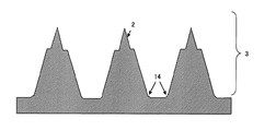
図3に示す通り、凸部2の断面形状は、研削刃11の先端に形成された傾斜面(斜面A12および斜面B13および段差面14)の傾きに一致する側壁形状を有し、側壁面と底面が交わる部分は、図2研削刃11の先端に形成された角取り面8に対応した裾を持った形状14となる。
また、針状体は用いられる研削面の形状によって様々な側面形状を形成することが可能となる。図3では、二段の段差形状を持つ針状体の例を示したが、もちろんこれに限定されるわけではない。あらかじめ研削刃の形状を多段構造に加工することで、針状体もそれに準じた多段構造を形成することができる。
加えて、この研削面の斜面間はエッジが存在しない滑らかな形状によって繋がっていても良い。この場合、底面から頂点にかけて曲線的な形状変化を持った針状体を形成することができ、これも用いる研削刃の形状によって適宜選択することが可能である。
Next, the grooves are sequentially formed in the same manner as the groove A'22, and as shown in FIG. 2 (f), a desired number of
At this time, the number of needle-like bodies arranged in an array to be manufactured is determined by the number of
As shown in FIG. 3, the cross-sectional shape of the
Also, the needle-like body can be formed in various side shapes depending on the shape of the grinding surface used. Although FIG. 3 shows an example of a needle-like body having a two-step shape, it is of course not limited to this. By processing the shape of the grinding blade into a multi-stage structure in advance, the acicular body can also form a multi-stage structure according to it.
In addition, the inclined surfaces of the grinding surface may be connected by a smooth shape having no edge. In this case, a needle-like body having a curved shape change from the bottom surface to the apex can be formed, and this can also be appropriately selected depending on the shape of the grinding blade used.
図3では、凸部2の断面形状において側壁面と底面が交わる部分が、円弧状の裾の形状になる例を示したが、側壁面と底面とが交わる角度よりも小さい角度で交わるように少なくとも1つの補助平面を形成することでも、穿刺時に針状体基底部に集中する応力を緩和することが出来る。この場合、研削刃11の先端加工時に、傾斜面7と研削刃先端面5が交わって成す頂点部分を面取りするように、少なくとも1つの補助平面を形成した研削刃を用いる。
In FIG. 3, the example in which the portion where the side wall surface and the bottom surface intersect with each other in the cross-sectional shape of the
次に、前記溝Aと交差するように溝Bを設け、前記交差溝Bと平行となるように交差溝B’を設ける。このとき、溝A21および溝A´22を設けて凸部が表面に形成された基材3を回転させることで、溝A21および溝A´22を設けた条件と同等に交差溝Bおよび交差溝B’を形成することが出来る。上述の場合、溝Aおよび溝A´と、交差溝Bおよび交差溝B’との交差角度は凸部が表面に形成された基材3の回転角度と同等となる。
Next, a groove B is provided so as to intersect with the groove A, and an intersecting groove B ′ is provided so as to be parallel to the intersecting groove B. At this time, the groove A21 and the groove A'22 are provided, and the
図4に、凸部2が表面に形成された基材3を90°回転して、前記の溝形成工程と同じ条件で研削加工を実施した例を斜視図で示す。この場合、研削されずに残る部分が、図4に示す通り、アレイ状の多段四角錐24となり、支持基板23上にアレイ状の針状体25が得られる。図4では多段四角錐24と支持基板23が角を成して接続されているが、前述した面取り加工を施した研削刃11を用いることで、角錐の基底部に緩やかな裾の形状を持たせることが出来る。また、溝斜面は選択した研削刃の粒径に依存した表面粗さの分布を持つ。
FIG. 4 is a perspective view showing an example in which the
また、交差溝Bおよび交差溝と平行な交差溝B’を設ける工程は複数回行っても良い。前記工程の施工回数、および、溝同士が交差する角度を制御することにより、多様な底面の形状を有する錐状の針状体を製造することが出来る。
例えば、交差溝Bおよび交差溝と平行な交差溝B’を設ける工程を一回行い、2方向の研削加工をそれぞれ60°ずらして実施する場合、底面がひし形である四角錐形状が得られる。このとき、ひし形の頂角は、対向する頂点が60°および120°に成る。
また、交差溝および交差溝と平行な交差溝’を設ける工程を二回行い、3方向に研削加工を行えば、底面が六角錐形状の針状体が得られる。
Further, the step of providing the intersecting groove B and the intersecting groove B ′ parallel to the intersecting groove may be performed a plurality of times. By controlling the number of executions of the process and the angle at which the grooves intersect, cone-shaped needles having various bottom shapes can be manufactured.
For example, when the process of providing the intersection groove B and the intersection groove B ′ parallel to the intersection groove is performed once and the two-direction grinding is performed by shifting by 60 °, a quadrangular pyramid shape having a rhombus at the bottom is obtained. At this time, the apex angle of the rhombus is 60 ° and 120 ° at the opposite apexes.
Further, by performing the process of providing the intersecting groove and the intersecting groove ′ parallel to the intersecting groove twice and grinding in three directions, a needle-like body having a hexagonal pyramid shape on the bottom surface can be obtained.
また、上記の工程で得られた針状体群の周辺には、場合によっては針状体ではない凸部が残留する。これを除去する必要がある場合には、追加加工で凸部を除去すればよい。 Moreover, the convex part which is not a needle-like body may remain in the periphery of the needle-like body group obtained by said process depending on the case. If it is necessary to remove this, the convex portion may be removed by additional processing.
以上より、研削刃の断面形状、工程の施工回数、および、溝同士が交差する角度を制御することにより、任意の表面形状かつ任意の多角底面を成した錐状の針状体を製造することが出来る。また、線状に溝を設けることで、列毎に針状体を作成することが出来るため、特に、アレイ状に配列された針状体を製造する場合、一括で形成することが可能となる。 From the above, by manufacturing the cross-sectional shape of the grinding blade, the number of executions of the process, and the angle at which the grooves intersect, a conical needle-like body having an arbitrary surface shape and an arbitrary polygonal bottom is manufactured. I can do it. In addition, since the needle-like bodies can be created for each column by providing the linear grooves, it is possible to form the needle-like bodies in a lump, particularly when manufacturing the needle-like bodies arranged in an array. .
<転写加工成形>
本発明の針状体製造方法は、更に、形成された針状体を原版として転写加工成形を行っても良い。
以下、転写加工成形について図5を用いながら具体的に、説明を行う。
<Transfer processing molding>
In the method for producing a needle-shaped body of the present invention, transfer processing molding may be further performed using the formed needle-shaped body as an original plate.
Hereinafter, the transfer processing molding will be specifically described with reference to FIG.
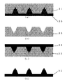
図5(a)では、原版30に複製材料31を充填する。このとき添加剤等を加えて良い。複製材料硬化の後、図5(b)のように、複製材料31を原版30から剥離することで凹型の複製版33を形成する。複製版を作製することで、同一の複製版から多量の針状体を製造することが出来るため、生産コストを抑制し、生産性を高めることが可能となる。
In FIG. 5A, the
また、複製版作製工程に於いては、微細領域での再現性を高めるために脱泡工程を行うことが好ましい。脱泡工程は公知の脱泡法を用いて良い。例えば、真空脱泡、遠心脱泡、攪拌脱泡等の脱泡方法を用いて行うことが出来る。 Further, in the duplicate plate production process, it is preferable to perform a defoaming process in order to improve reproducibility in a fine region. A known defoaming method may be used for the defoaming step. For example, it can be performed using a defoaming method such as vacuum defoaming, centrifugal defoaming, stirring defoaming or the like.
複製材料は、特に制限されるものではないが、原版を転写し得る形状追従性、後述する転写加工成型における転写性、耐久性および離型性を考慮した材質を選択することが出来る。例えば、ニッケルやシリコーン樹脂材を用いることが出来る。しかし、これのみに限定されるものでは無い。ニッケルを選択した場合の複製方法としては、メッキ法、PVD法等が挙げられる。また、複製材料中の不純物を除去するために精製工程を加えても良い。 The replication material is not particularly limited, and a material can be selected in consideration of the shape followability capable of transferring the original plate, transferability in transfer processing molding described later, durability, and releasability. For example, nickel or a silicone resin material can be used. However, it is not limited to this. Examples of a replication method when nickel is selected include a plating method and a PVD method. Further, a purification step may be added to remove impurities in the replication material.
複製版作製の際には、樹脂の複製材料に対して任意の添加剤を加えることで硬化時間や硬化形状の制御等の機能を持たせることが可能である。ここで用いられる添加剤は特に制限されず、複製材料との反応により弊害が生じない材料を選択的に用いても良い。用いられる材料の例として、無機材料や水、有機溶剤が挙げられるが、複製版表面形状の形成に影響を及ぼすことができる他の材料であっても良く、これに限定されるもではない。添加剤を加えるタイミングは特に限定されず、充填前から複製材料が硬化するまでの間に添加可能である。好ましくは充填前であり、これにより添加剤の均一な分散を促すことが出来る。また、使用される添加剤は一種のみに限定されず、種類の異なる添加剤を複数用いても良い。また、その添加量は任意の表面形状とするために、適宜その加減を変更することが出来るものである。また、添加剤を完全に除去するために、複製版硬化後に複製版の洗浄工程を加えても良い。 When producing a duplicate plate, it is possible to provide functions such as curing time and curing shape control by adding an arbitrary additive to the resin duplication material. The additive used here is not particularly limited, and a material that does not cause harmful effects by reaction with the replication material may be selectively used. Examples of the materials used include inorganic materials, water, and organic solvents, but other materials that can affect the formation of the replica plate surface shape may be used, and the present invention is not limited thereto. The timing at which the additive is added is not particularly limited, and can be added before the replica material is cured before filling. Preferably, it is before filling, which can promote uniform dispersion of the additive. Moreover, the additive used is not limited to only one type, and a plurality of different types of additives may be used. Moreover, in order to make the addition amount into arbitrary surface shapes, the addition and subtraction can be changed as appropriate. In order to completely remove the additive, a duplicate plate washing step may be added after the duplicate plate is cured.
このとき、添加剤混入前の複製材料の粘度は1Pa・sから100Pa・sであることが好ましい。粘度が低すぎる場合には添加剤を複製材料中に固定することが出来ず、二層化してしまう。また、粘度が高すぎる場合は、複製材料中に添加剤を均等に分散させることができず塊として存在してしまう事となる。 At this time, the viscosity of the replication material before mixing with the additive is preferably 1 Pa · s to 100 Pa · s. If the viscosity is too low, the additive cannot be fixed in the replication material, resulting in two layers. On the other hand, if the viscosity is too high, the additive cannot be evenly dispersed in the replication material and will exist as a lump.
次に、複製版を用いた転写加工成型について説明する。
図5(c)では、複製版33に成形材34を充填する。成形材は特に制限されないが、穿刺部となる複製針状体においては生体適合性材料である医療用シリコーン樹脂や、マルトース、ポリ乳酸、デキストラン、キチン、キトサン、糖質、ポリカーボネート等を用いることが好ましい。生体適合性材料を用いれば、針状体が折れて体内に取り残された場合も、無害であるという効果を有する。このときの成形材34の充填方法についての制限は無いが、生産性の観点から、インプリント法、ホットエンボス法、射出成形法、押し出し成形法およびキャスティング法を好適に用いることが出来る。
Next, transfer processing molding using a duplicate plate will be described.
In FIG. 5 (c), the duplication plate 33 is filled with a
成形材34充填の後、これを複製版33から剥離し、任意の複製針状体35を得る。このとき、複製版の剥離性を向上させるために、複製針状体の材料の充填前に、複製版の表面上に離型効果を増すための離型層を形成してもよい(図示せず)。離型層としては、例えば広く知られているフッ素系の樹脂を用いることができる。また、離型層の形成方法としては、PVD法、CVD法、スピンコート法、ディップコート法等の薄膜形成手法を好適に用いることができる。
After filling with the
転写成形方法はその充填材料を選択することで、機械的もしくは化学的な直接加工を用いて針状体を作製することが困難である材料においても形成が可能となり、尚且つ、大量の製品を効率良く低コストで製造することが可能である。しかも、転写成形のための材料には生体適合材料を用いた場合、生体に低負荷の材料を用いた複製針状体を製造することが可能となる。生体適合材料を用いれば、微細な針状体が折れて、体内に取り残された場合も、無害であるという効果を有する。 In the transfer molding method, by selecting the filling material, it is possible to form even a material in which it is difficult to produce a needle-like body using mechanical or chemical direct processing, and a large amount of products can be formed. It is possible to manufacture efficiently and at low cost. In addition, when a biocompatible material is used as the material for transfer molding, it is possible to manufacture a replicated needle-like body using a material having a low load on the living body. If a biocompatible material is used, even if a fine needle-like body is broken and left in the body, it has an effect that it is harmless.
以下、本発明の針状体の製造方法について、具体的に一例を挙げながら説明を行う。当然のことながら、本発明の針状体の製造方法は下記実施例に限定されず、各工程において類推できる他の製造方法をも含むものとする。 Hereinafter, the method for producing the needle-shaped body of the present invention will be described with specific examples. Naturally, the manufacturing method of the acicular body of the present invention is not limited to the following examples, and includes other manufacturing methods that can be inferred in each step.
まず、ダイヤモンド砥粒を含有した研削刃の先端部を、ダイヤモンド砥石による研磨加工によって、後述する所望の形状に加工した。
図1は円盤状の研削刃先端の部分断面図である。図1(a)に示す通り、研磨加工前の研削刃12の断面形状は、研削刃側壁面4と研削刃先端面5が90°の角を成して交わり、頂点6を形成している。
この研削刃12を、ダイヤモンド砥石を用いて加工し、研削刃11を得た。
研削刃11は、図1(b)に示す通り、斜面A12および斜面B13および段面14を有し、且つ傾斜面7と研削刃先端面5が交わって成す頂点部分は概角取り面8を有する形状に加工された。
本実施例では、厚みが1mmの研削刃を用い、研削刃先端面5が幅180μmとなり、研削刃側壁面4と傾斜面7との成す角度が160°となるように、研削刃の先端を研磨加工した。このとき、段面14の幅は10μmとなるように加工した。また、斜面Aの角度15と斜面Bの角度16は同一の角度となるようにした。
First, the tip of a grinding blade containing diamond abrasive grains was processed into a desired shape to be described later by polishing with a diamond grindstone.
FIG. 1 is a partial cross-sectional view of the tip of a disc-shaped grinding blade. As shown in FIG. 1A, the cross-sectional shape of the grinding
The grinding
As shown in FIG. 1B, the grinding
In this embodiment, a grinding blade having a thickness of 1 mm is used, the tip of the grinding blade is 180 μm wide, and the tip of the grinding blade is polished so that the angle formed by the
次に、前記の通り先端を加工した研削刃による研削加工で、セラミックス基材の表面に溝Aを形成する工程を実施した。
まず図2(a)に示す通り、一辺が30mmの正方形で、厚さ3mmのセラミックス基材を準備し、続いて図2(b)に示す通り、研削刃を回転させながらセラミックス基材の表面を深さ300μmとなるように研削加工し、長さ30mmの溝を形成した。
Next, the process of forming the groove | channel A in the surface of the ceramic base material was implemented by the grinding process by the grinding blade which processed the front-end | tip as above-mentioned.
First, as shown in FIG. 2A, a ceramic substrate having a square of 30 mm on a side and a thickness of 3 mm is prepared. Subsequently, as shown in FIG. 2B, the surface of the ceramic substrate is rotated while rotating the grinding blade. Was ground to a depth of 300 μm to form a groove having a length of 30 mm.
上記研削加工によって、図2(c)に示す通り、溝Aが形成された。溝Aの開口上部の幅は約418μm、深さは300μmとなった。
溝Aの側壁面の傾きは、研削刃の先端に形成された傾斜面の傾きに対応し、本実施例ではセラミックス基材の表面と溝Aの側壁面との成す角度は110°となった。同様に、溝Aの側壁面と底面が交わる部分は、研削刃の先端に形成された角取り面に対応した裾を持った形状となった。
By the grinding process, a groove A was formed as shown in FIG. The width of the upper opening of the groove A was about 418 μm and the depth was 300 μm.
The inclination of the side wall surface of the groove A corresponds to the inclination of the inclined surface formed at the tip of the grinding blade. In this example, the angle formed by the surface of the ceramic substrate and the side wall surface of the groove A was 110 °. . Similarly, the portion where the side wall surface and the bottom surface of the groove A intersect each other has a shape having a skirt corresponding to the chamfered surface formed at the tip of the grinding blade.
次に溝A´を基材1の表面に加工する工程を実施した。
図2(d)に示すように、溝Aの隣に、溝Aと同一の条件で研削刃によって溝を加工した。このとき、溝Aに対して、平行に研削した。これにより、図2(e)に示す通り、深さ300μmで長さ3mmの溝A´が、溝Aに隣接して形成された。溝Aと溝A´の間には、先端形状が先鋭な凸部が形成された。
Next, the process of processing groove | channel A 'to the surface of the
As shown in FIG. 2D, a groove was machined by a grinding blade adjacent to the groove A under the same conditions as the groove A. At this time, grinding was performed parallel to the groove A. As a result, a groove A ′ having a depth of 300 μm and a length of 3 mm was formed adjacent to the groove A as shown in FIG. A convex portion having a sharp tip shape was formed between the groove A and the groove A ′.
凸部2の高さは、研削加工深さ、研削刃の先端傾斜面の角度、および溝Aと溝A´重なり距離によって決定する。本実施例における凸部2の高さは約290μm、根元の幅は約231μmとなった。研削刃先端の傾斜面の重なりで形成された凸部の先端は、角度40°の頂点となった。
The height of the
次に、溝A´を形成したのと同様に順次溝を形成していき、図2(f)に示す通り、凸部を所望の数だけ形成して、概ね三角形の断面形状を有する凸部が表面に形成された基材を得た。本実施例においては、合計6本の溝を作製した。6本の溝形成によって、5本の凸部が形成された。図3に示す通り、凸部の断面形状は、研削刃の先端に形成された傾斜面の傾きに一致する側壁傾斜を有し、側壁面と底面が交わる部分は、図1研削刃の先端に形成された角取り面に対応した裾を持った形状となった。 Next, grooves are sequentially formed in the same manner as the groove A ′, and as shown in FIG. 2 (f), a desired number of protrusions are formed, and a protrusion having a generally triangular cross-sectional shape. A base material having a surface formed thereon was obtained. In this example, a total of 6 grooves were produced. Five protrusions were formed by forming six grooves. As shown in FIG. 3, the cross-sectional shape of the convex portion has a side wall inclination that matches the inclination of the inclined surface formed at the tip of the grinding blade, and the portion where the side wall surface and the bottom surface intersect with each other at the tip of the grinding blade in FIG. It became a shape with a hem corresponding to the formed chamfered surface.
次に、前期6本の溝形成工程によって5本形成された凸部が表面に形成された基材を、90°回転し、前記の溝形成工程と同じ条件で研削加工を実施した。これにより、交差溝Bおよび交差溝B’が併せて5本形成され、その結果研削されずに残る部分が、図4に示す通り、アレイ状の正四角錐となり、支持基板上にアレイ状の配列された針状体が得られた。本実施例においては、針状体は5列5行のアレイ状に並んだ25の針状体が得られた。このとき得られた針状体は四角錐であり、先端角が40°、高さが約162μm、底面の一辺の幅が231μmとなった。また、角錐側面には表面粗さの差によって生じた境界線が確認でき、先端部が基底部に比べ表面粗さが低減された構造を持つ針状体となった。 Next, the base material on which the five convex portions formed by the previous six groove forming steps were formed was rotated by 90 °, and grinding was performed under the same conditions as in the groove forming step. As a result, five intersecting grooves B and five intersecting grooves B ′ are formed. As a result, the portion that remains without being ground becomes an array of regular quadrangular pyramids as shown in FIG. A needle-like body was obtained. In this example, 25 needle-like bodies arranged in an array of 5 columns and 5 rows were obtained. The needle-like body obtained at this time was a quadrangular pyramid, the tip angle was 40 °, the height was about 162 μm, and the width of one side of the bottom surface was 231 μm. Moreover, the boundary line produced by the difference in surface roughness was confirmed on the side surface of the pyramid, and the tip portion became a needle-like body having a structure in which the surface roughness was reduced compared to the base portion.
次に、作製した針状体を複製するため、作製した針状体を母型とし、前記母型から複製版を作り、転写加工成形を行う工程を実施した。
まず、メッキ法によって、針状体の表面にニッケル膜を600μm形成した。次に前記ニッケル膜を針状体から剥離し、複製版を作製した。次に、上記複製版に対し、インプリント法を用いて複製針状体の作製を行った。充填する複製針状体材料として、生体適合性材料であるポリカーボネートを用いた。以上の工程により、生体適合性樹脂であるポリカーボネートで構成された先鋭な複製針状体を製造することが出来た。
Next, in order to replicate the produced needle-like body, the produced needle-like body was used as a mother die, a duplicate plate was made from the mother die, and a transfer processing molding process was performed.
First, a nickel film of 600 μm was formed on the surface of the needle-like body by a plating method. Next, the nickel film was peeled off from the acicular body to produce a duplicate plate. Next, a replica needle was produced using the imprint method for the duplicate plate. Polycarbonate, which is a biocompatible material, was used as the replica needle material to be filled. Through the above steps, a sharp replica needle-like body made of polycarbonate, which is a biocompatible resin, could be manufactured.
本発明の針状体製造方法は、医薬創薬に用いる針状体のみならず、錐形状の3次元構造パターンを形成することが求められる広範な分野に利用することが期待される。
前記広範な分野としては、例えば、半導体デバイス、光学素子、配線回路、データストレージメディア(ハードディスク、光学メディアなど)、医療用部材(分析検査用チップ、マイクロニードルなど)、化粧品用途マイクローニードル、バイオデバイス(バイオセンサ、細胞培養基板など)、精密検査機器用部材(検査プローブ、試料保持部材など)、ディスプレイパネル、パネル部材、エネルギーデバイス(太陽電池、燃料電池など)、マイクロ流路、マイクロリアクタ、MEMSデバイスなどが挙げられる。
The needle-shaped body production method of the present invention is expected to be used not only for needle-shaped bodies used for pharmaceutical drug discovery but also in a wide range of fields where a cone-shaped three-dimensional structure pattern is required.
Examples of the broad field include semiconductor devices, optical elements, wiring circuits, data storage media (hard disks, optical media, etc.), medical members (analytical inspection chips, microneedles, etc.), cosmetic use microneedles, biotechnology, etc. Devices (biosensors, cell culture substrates, etc.), precision inspection equipment members (inspection probes, sample holding members, etc.), display panels, panel members, energy devices (solar cells, fuel cells, etc.), microchannels, microreactors, MEMS Devices.
1…基材
2…凸部
3…凸部が表面に形成された基材
4…研削刃側壁面
5…研削刃先端面
6…研削刃先端部の直行頂点
7…傾斜面
8…部分的円弧形状
10…従来の研削刃先端部断面
11…先端を加工した研削刃先端部断面
12…斜面A
13…斜面B
14…段差段面
15…斜面Aの角度
16…斜面Bの角度
21…溝A
22…溝A´
23…針状体の支持基板、
24…針状体、
25…アレイ状に配列された針状体
30…原版金型
31…複製材料
33…複製版
34…成形材
35…針状体
DESCRIPTION OF
13 ... Slope B
14 ... Stepped surface 15 ... Angle 16 of slope A ...
22 ... Groove A '
23 ... the support substrate of the needle-like body,
24 ... acicular body,
25 ... Needle-
Claims (5)
研削加工を用いて基板に第1の方向と交差する第2の方向に沿って互いに平行な複数の第2の線状溝を形成する工程と、を備え、
前記研削加工に用いる研削刃の断面形状は、先端面と側面との間に傾斜面が形成された形状であり、前記傾斜面に段差段面を有する研削刃であること
を特徴とする針状体製造方法。 Forming a plurality of first linear grooves parallel to each other in the first direction on the substrate using grinding;
Forming a plurality of second linear grooves parallel to each other along a second direction intersecting the first direction using a grinding process, and
The cross-sectional shape of the grinding blade used for the grinding process is a shape in which an inclined surface is formed between a tip surface and a side surface, and the needle shape is a grinding blade having a stepped surface on the inclined surface Body manufacturing method.
を特徴とした針状体製造方法。 A needle-shaped body manufacturing comprising: forming a replica plate using the needle-shaped body manufactured using the needle-shaped body manufacturing method according to claim 1 as an original plate, and performing transfer processing molding using the replica plate. Method.
研削刃の断面形状は、先端面と側面との間に傾斜面が形成された形状であり、
前記傾斜面に段差段面を有する断面形状であること
を特徴とする研削刃。 A grinding blade used for micromachining,
The cross-sectional shape of the grinding blade is a shape in which an inclined surface is formed between the tip surface and the side surface,
A grinding blade having a cross-sectional shape having a stepped surface on the inclined surface.
前記段差段面の前後で、傾斜面の傾斜角度が異なること
を特徴とする研削刃。 The grinding blade according to claim 3,
A grinding blade characterized in that the inclination angle of the inclined surface differs before and after the stepped surface.
該段差により先鋭部側の傾斜面と根元部側の傾斜面とが区別され、
前記先鋭部側の傾斜面の傾斜角度と前記根元部側の傾斜面の傾斜角度とが異なることを
特徴とした針状体。 A stepped surface is provided on the inclined surface,
The step distinguishes the inclined surface on the sharp side and the inclined surface on the root side,
An acicular body characterized in that an inclination angle of the inclined surface on the sharpened portion side is different from an inclination angle of the inclined surface on the root portion side.
Priority Applications (1)
| Application Number | Priority Date | Filing Date | Title |
|---|---|---|---|
| JP2008226784A JP5401061B2 (en) | 2008-09-04 | 2008-09-04 | Acicular body manufacturing method and grinding blade |
Applications Claiming Priority (1)
| Application Number | Priority Date | Filing Date | Title |
|---|---|---|---|
| JP2008226784A JP5401061B2 (en) | 2008-09-04 | 2008-09-04 | Acicular body manufacturing method and grinding blade |
Publications (2)
| Publication Number | Publication Date |
|---|---|
| JP2010057704A true JP2010057704A (en) | 2010-03-18 |
| JP5401061B2 JP5401061B2 (en) | 2014-01-29 |
Family
ID=42185201
Family Applications (1)
| Application Number | Title | Priority Date | Filing Date |
|---|---|---|---|
| JP2008226784A Active JP5401061B2 (en) | 2008-09-04 | 2008-09-04 | Acicular body manufacturing method and grinding blade |
Country Status (1)
| Country | Link |
|---|---|
| JP (1) | JP5401061B2 (en) |
Cited By (12)
| Publication number | Priority date | Publication date | Assignee | Title |
|---|---|---|---|---|
| WO2013171907A1 (en) * | 2012-05-18 | 2013-11-21 | 大勝 明 | Injection needle and kit preparation |
| JP2013248299A (en) * | 2012-06-01 | 2013-12-12 | Dainippon Printing Co Ltd | Microneedle device |
| JP2014079557A (en) * | 2012-09-28 | 2014-05-08 | Kosumedei Seiyaku Kk | Microneedle holding medicament in step |
| JP2014188329A (en) * | 2013-03-28 | 2014-10-06 | Toppan Printing Co Ltd | Method for manufacturing needle-like body |
| JP2017071109A (en) * | 2015-10-06 | 2017-04-13 | 富士フイルム株式会社 | Die for resin molding, and method of making a resin molding using the same |
| JP2017094180A (en) * | 2017-01-27 | 2017-06-01 | 大日本印刷株式会社 | Microneedle device |
| JP2017144307A (en) * | 2017-06-01 | 2017-08-24 | 大日本印刷株式会社 | Microneedle device |
| JP2018015662A (en) * | 2017-11-06 | 2018-02-01 | 大日本印刷株式会社 | Microneedle device |
| DE102011005515B4 (en) | 2010-03-15 | 2018-06-28 | Denso Corporation | A communication network system having a high-ranked network and low-ranked networks, an exchange port for connecting the high-ranking network and a low-ranked network, microcomputers for controlling connection between a low-ranking network transmission line and a high-level network transmission line, and communication transceivers which is connected to the transmission line of a low-rank network and the transmission line of the high-order network |
| JP2020508801A (en) * | 2017-09-08 | 2020-03-26 | エス‐スキン.カンパニー リミテッド | Microneedle template and microneedle manufactured using the same |
| CN111035849A (en) * | 2018-10-15 | 2020-04-21 | 富士胶片株式会社 | Method for manufacturing original plate having needle-like projections and method for manufacturing microneedle array |
| CN114828936A (en) * | 2019-12-26 | 2022-07-29 | 富士胶片株式会社 | Method for manufacturing microneedle array |
Citations (2)
| Publication number | Priority date | Publication date | Assignee | Title |
|---|---|---|---|---|
| JP2003238347A (en) * | 2002-02-18 | 2003-08-27 | Nano Device & System Research Inc | Functional micropile and method for producing the same |
| WO2008013282A1 (en) * | 2006-07-27 | 2008-01-31 | Toppan Printing Co., Ltd. | Method for producing microneedle |
-
2008
- 2008-09-04 JP JP2008226784A patent/JP5401061B2/en active Active
Patent Citations (2)
| Publication number | Priority date | Publication date | Assignee | Title |
|---|---|---|---|---|
| JP2003238347A (en) * | 2002-02-18 | 2003-08-27 | Nano Device & System Research Inc | Functional micropile and method for producing the same |
| WO2008013282A1 (en) * | 2006-07-27 | 2008-01-31 | Toppan Printing Co., Ltd. | Method for producing microneedle |
Cited By (16)
| Publication number | Priority date | Publication date | Assignee | Title |
|---|---|---|---|---|
| DE102011005515B4 (en) | 2010-03-15 | 2018-06-28 | Denso Corporation | A communication network system having a high-ranked network and low-ranked networks, an exchange port for connecting the high-ranking network and a low-ranked network, microcomputers for controlling connection between a low-ranking network transmission line and a high-level network transmission line, and communication transceivers which is connected to the transmission line of a low-rank network and the transmission line of the high-order network |
| WO2013171907A1 (en) * | 2012-05-18 | 2013-11-21 | 大勝 明 | Injection needle and kit preparation |
| JP2013248299A (en) * | 2012-06-01 | 2013-12-12 | Dainippon Printing Co Ltd | Microneedle device |
| JP2014079557A (en) * | 2012-09-28 | 2014-05-08 | Kosumedei Seiyaku Kk | Microneedle holding medicament in step |
| WO2014126052A1 (en) * | 2013-02-14 | 2014-08-21 | コスメディ製薬株式会社 | Medicine-holding microneedle array and process for producing same |
| US20160001053A1 (en) * | 2013-02-14 | 2016-01-07 | Cosmed Pharmaceutical Co., Ltd. | Drug-holding microneedle array and manufacturing method thereof |
| US10994111B2 (en) | 2013-02-14 | 2021-05-04 | Cosmed Pharmaceutical Co., Ltd. | Drug-holding microneedle array and manufacturing method thereof |
| JP2014188329A (en) * | 2013-03-28 | 2014-10-06 | Toppan Printing Co Ltd | Method for manufacturing needle-like body |
| JP2017071109A (en) * | 2015-10-06 | 2017-04-13 | 富士フイルム株式会社 | Die for resin molding, and method of making a resin molding using the same |
| JP2017094180A (en) * | 2017-01-27 | 2017-06-01 | 大日本印刷株式会社 | Microneedle device |
| JP2017144307A (en) * | 2017-06-01 | 2017-08-24 | 大日本印刷株式会社 | Microneedle device |
| JP2020508801A (en) * | 2017-09-08 | 2020-03-26 | エス‐スキン.カンパニー リミテッド | Microneedle template and microneedle manufactured using the same |
| JP2018015662A (en) * | 2017-11-06 | 2018-02-01 | 大日本印刷株式会社 | Microneedle device |
| CN111035849A (en) * | 2018-10-15 | 2020-04-21 | 富士胶片株式会社 | Method for manufacturing original plate having needle-like projections and method for manufacturing microneedle array |
| US11597122B2 (en) | 2018-10-15 | 2023-03-07 | Fujifilm Corporation | Manufacturing method of plate precursor having needle-like protrusion, and manufacturing method of microneedle array |
| CN114828936A (en) * | 2019-12-26 | 2022-07-29 | 富士胶片株式会社 | Method for manufacturing microneedle array |
Also Published As
| Publication number | Publication date |
|---|---|
| JP5401061B2 (en) | 2014-01-29 |
Similar Documents
| Publication | Publication Date | Title |
|---|---|---|
| JP5401061B2 (en) | Acicular body manufacturing method and grinding blade | |
| JP5538457B2 (en) | Manufacturing method of microneedle | |
| KR102187985B1 (en) | Needle-like structure and method for manufacturing same | |
| JP2008237673A (en) | Needle shape body and its manufacturing method | |
| JP5568324B2 (en) | Microneedle manufacturing method | |
| JP2009233793A (en) | Needle-like article, and method of and device for manufacturing replicative needle-like article | |
| US11597122B2 (en) | Manufacturing method of plate precursor having needle-like protrusion, and manufacturing method of microneedle array | |
| JP5173331B2 (en) | Needle-shaped body chip and manufacturing method thereof | |
| JP2010075374A (en) | Needle-shaped body device and method of manufacturing the same | |
| JP2010030201A (en) | Manufacturing of needle-like body, needle-like body, and duplicate plate of needle-like body | |
| JP2009225987A (en) | Needle shape body | |
| JP5515254B2 (en) | Acicular body manufacturing method and acicular body | |
| JP2017074196A (en) | Needle device and applicator with the same | |
| JP6060547B2 (en) | Manufacturing method of needle-shaped body | |
| JP2009045312A (en) | Formation method and production method of needle-like body, and needle-like body | |
| JP5205016B2 (en) | Needle-like body, needle-like body manufacturing method | |
| JP5593355B2 (en) | Needle-like body and method for producing needle-like body | |
| JP2009190213A (en) | Method of manufacturing acicular body |
Legal Events
| Date | Code | Title | Description |
|---|---|---|---|
| A711 | Notification of change in applicant |
Free format text: JAPANESE INTERMEDIATE CODE: A711 Effective date: 20100625 |
|
| RD03 | Notification of appointment of power of attorney |
Free format text: JAPANESE INTERMEDIATE CODE: A7423 Effective date: 20110527 |
|
| A621 | Written request for application examination |
Free format text: JAPANESE INTERMEDIATE CODE: A621 Effective date: 20110825 |
|
| A977 | Report on retrieval |
Free format text: JAPANESE INTERMEDIATE CODE: A971007 Effective date: 20121220 |
|
| A131 | Notification of reasons for refusal |
Free format text: JAPANESE INTERMEDIATE CODE: A131 Effective date: 20130108 |
|
| A521 | Request for written amendment filed |
Free format text: JAPANESE INTERMEDIATE CODE: A523 Effective date: 20130311 |
|
| TRDD | Decision of grant or rejection written | ||
| A01 | Written decision to grant a patent or to grant a registration (utility model) |
Free format text: JAPANESE INTERMEDIATE CODE: A01 Effective date: 20131001 |
|
| A61 | First payment of annual fees (during grant procedure) |
Free format text: JAPANESE INTERMEDIATE CODE: A61 Effective date: 20131028 |
|
| R150 | Certificate of patent or registration of utility model |
Ref document number: 5401061 Country of ref document: JP Free format text: JAPANESE INTERMEDIATE CODE: R150 Free format text: JAPANESE INTERMEDIATE CODE: R150 |
|
| R250 | Receipt of annual fees |
Free format text: JAPANESE INTERMEDIATE CODE: R250 |
|
| R250 | Receipt of annual fees |
Free format text: JAPANESE INTERMEDIATE CODE: R250 |
|
| R250 | Receipt of annual fees |
Free format text: JAPANESE INTERMEDIATE CODE: R250 |
|
| R250 | Receipt of annual fees |
Free format text: JAPANESE INTERMEDIATE CODE: R250 |
|
| R250 | Receipt of annual fees |
Free format text: JAPANESE INTERMEDIATE CODE: R250 |
|
| R250 | Receipt of annual fees |
Free format text: JAPANESE INTERMEDIATE CODE: R250 |
|
| R250 | Receipt of annual fees |
Free format text: JAPANESE INTERMEDIATE CODE: R250 |
|
| R250 | Receipt of annual fees |
Free format text: JAPANESE INTERMEDIATE CODE: R250 |
|
| S533 | Written request for registration of change of name |
Free format text: JAPANESE INTERMEDIATE CODE: R313533 |
|
| R350 | Written notification of registration of transfer |
Free format text: JAPANESE INTERMEDIATE CODE: R350 |