JP2010056865A - Image capturing apparatus - Google Patents
Image capturing apparatus Download PDFInfo
- Publication number
- JP2010056865A JP2010056865A JP2008219544A JP2008219544A JP2010056865A JP 2010056865 A JP2010056865 A JP 2010056865A JP 2008219544 A JP2008219544 A JP 2008219544A JP 2008219544 A JP2008219544 A JP 2008219544A JP 2010056865 A JP2010056865 A JP 2010056865A
- Authority
- JP
- Japan
- Prior art keywords
- imaging
- light receiving
- optical system
- shutter
- image
- Prior art date
- Legal status (The legal status is an assumption and is not a legal conclusion. Google has not performed a legal analysis and makes no representation as to the accuracy of the status listed.)
- Pending
Links
Images


Abstract
Description
本発明は、2つの撮影光学系による被写体像を1つの撮像素子に結像させて立体画像を形成する左右2つの画像データを生成する撮像装置に関するものである。 The present invention relates to an imaging apparatus that generates left and right image data for forming a stereoscopic image by forming subject images from two imaging optical systems on one imaging element.
立体画像を撮影する立体撮像装置は、被写体画像の右目情報と左目情報の視差によって立体画像を生成するものであるが、その方法の1つに、前記右目情報と左目情報を別々の撮影光学系によって取り込み1つの撮像素子に結像させる方法がある。前記右目情報と左目情報の取り込み方法は、種々提案されている。例えば、下記特許文献1には、撮像素子の直前にレンチキュラレンズを配置し、前記2つの撮影光学系がレンチキュラレンズを通して結像する結像点を前記撮像素子上で1/2画素ピッチだけずれるように構成して、2つの結像点を交互に各画素上に位置するように前記撮像素子を所定周期で変位させる立体撮像装置が示されている。また、下記特許文献2には、メカシャッタを備えた2つの撮影光学系による撮影光をハーフミラーによって1つの撮像素子に結像させ、メカシャッタを交互に開いて右目情報と左目情報とを交互に且つ順次に取り込み立体画像を形成する撮像装置が記載されている。
しかしながら、前記特許文献1,2に示される被写体画像の取り込み方法は、いずれも左右の情報を交互に取り込む方法であるため、厳密には同一タイミングの画像ではない。また、レンチキュラレンズを移動させる駆動装置が必要であったり、撮影光を分割させるハーフミラーを備えなければならないなど、コストアップやスペースアップの問題があった。
However, the subject image capturing methods disclosed in
本発明は上記問題点に鑑み、レンチキュラレンズやハーフミラーを用いずに、立体撮影時には1つの撮像素子に右目情報と左目情報とを同一タイミングで取り込んで立体画像を形成する左右2つの画像データを生成するとともに、通常撮影時には2倍の画像情報を取得して高画質画像を提供できる撮像装置を提案する。 In view of the above problems, the present invention takes two right and left image data to form a stereoscopic image by capturing right-eye information and left-eye information at the same timing in one imaging element at the time of stereoscopic imaging without using a lenticular lens or a half mirror. An imaging apparatus that can generate and provide a high-quality image by acquiring double image information during normal shooting is proposed.
本発明による撮像装置は、第1の方向に偏光軸を有する第1偏光板が光路上に設けられた第1撮影光学系と、前記第1の方向と直交する第2の方向に偏光軸を有する第2偏光板が光路上に設けられた第2撮影光学系と、第1の方向に偏光軸を有する偏光板が設けられた第1受光素子と第2の方向に偏光軸を有する偏光板が設けられた第2受光素子とが同数づつ交互に格子状に配列され、前記第1撮影光学系と前記第2撮影光学系のそれぞれの被写体像が結像される撮像素子とを備え、前記撮像素子から画像データを読み出して立体画像を形成する左右2つの画像データを生成する。 An imaging apparatus according to the present invention includes a first imaging optical system in which a first polarizing plate having a polarization axis in a first direction is provided on an optical path, and a polarization axis in a second direction orthogonal to the first direction. A second imaging optical system having a second polarizing plate on the optical path, a first light receiving element having a polarizing plate having a polarization axis in the first direction, and a polarizing plate having a polarization axis in the second direction And the same number of second light-receiving elements arranged in a grid pattern, and imaging elements on which the respective subject images of the first photographing optical system and the second photographing optical system are formed, Image data is read from the image sensor and two left and right image data forming a stereoscopic image are generated.
前記第1受光素子及び前記第2受光素子は、隣接して正方形に配置された赤、緑、青を含む4個が1組を形成し、前記1組単位で前記第1受光素子と前記第2受光素子とが交互に配列されるようにすると良い。あるいは、前記撮像素子は、それぞれ正方格子状にベイヤー配列された前記第1受光素子及び前記第2受光素子が、互いに斜め45°に半ピッチ分ずれた位置に配置され、全体として市松配列されるようにすると良い。 In the first light receiving element and the second light receiving element, four pieces including red, green, and blue arranged adjacently in a square form one set, and the first light receiving element and the second light receiving element are formed in one set unit. The two light receiving elements are preferably arranged alternately. Alternatively, in the imaging device, the first light receiving elements and the second light receiving elements, which are arranged in a Bayer array in a square lattice pattern, are arranged at positions shifted by a half pitch from each other at an angle of 45 °, and are arranged in a checkered pattern as a whole. It is good to do so.
前記撮像装置は、立体撮影モードと通常撮影モードのいずれかを選択可能な撮影モード選択手段と、前記第1撮影光学系の光路を遮光する第1シャッタと、前記第2撮影光学系の光路を遮光する第2シャッタとを備えるとともに、前記第1偏光板は前記第1撮影光学系の光路上に進退自在に設けられ、前記撮影モード選択手段によって前記通常撮影モードが選択された場合には、前記第1偏光板が前記第1撮影光学系の光路上から退避するとともに前記第2シャッタが前記第2撮影光学系の光路を遮光する位置で保持された状態で被写体像の撮影が行われるようにすると良い。 The imaging apparatus includes a shooting mode selection unit that can select either a stereoscopic shooting mode or a normal shooting mode, a first shutter that blocks an optical path of the first shooting optical system, and an optical path of the second shooting optical system. A second shutter that shields light, and the first polarizing plate is provided so as to be movable back and forth on the optical path of the first photographing optical system, and when the normal photographing mode is selected by the photographing mode selecting means, The subject image is photographed in a state where the first polarizing plate is retracted from the optical path of the first photographing optical system and the second shutter is held at a position that blocks the optical path of the second photographing optical system. It is good to make it.
前記撮像装置は、前記第1及び第2撮影光学系はオートフォーカス手段を有し、前記オートフォーカス手段によって被写体までの距離が予め定められた距離よりも遠いことが検出された場合には、前記通常撮影モードが自動的に選択されるようにすると良い。 In the imaging apparatus, the first and second imaging optical systems have autofocus means, and when the autofocus means detects that the distance to the subject is longer than a predetermined distance, The normal shooting mode may be automatically selected.
前記撮像装置は、前記撮像素子の直前に第3シャッタを備え、前記第3シャッタによって前記撮像素子を遮光した後に、全ての前記受光素子から画像データを読み出すようにしても良い。 The imaging apparatus may include a third shutter immediately before the imaging element, and after the imaging element is shielded from light by the third shutter, image data may be read from all the light receiving elements.
前記第1及び第2シャッタは同じタイミングで開閉制御されて、被写体像の撮影が行われるようにしても良い。 The first and second shutters may be controlled to be opened and closed at the same timing so that a subject image is taken.
本発明による撮像装置は、互いに直交する偏光軸を有する2種類の偏光板を設けた左右の撮影光学系と、前記2種類の偏光板を交互に配列した受光素子を用いて、レンチキュラレンズやハーフミラーなどを設けることなく、左右の撮影画像情報を同一タイミングで取り込み、且つ別々に読み出すことを可能にして立体画像を形成する左右2つの画像データを生成するとともに、通常撮影時には2倍の画像情報を有する高画質画像を提供できる。 An imaging apparatus according to the present invention includes a left and right photographing optical system provided with two types of polarizing plates having polarization axes orthogonal to each other, and a light receiving element in which the two types of polarizing plates are alternately arranged, and a lenticular lens and a half. Without providing mirrors, left and right captured image information can be captured at the same timing and read out separately to generate two left and right image data to form a stereoscopic image, and twice as much image information during normal shooting It is possible to provide a high-quality image having
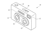
図1及び図2に示すように、本発明による3Dカメラ(撮像装置)10は、略直方体形状のカメラ本体11の前面に、2組の撮像レンズ12,13と、ストロボ発光部14、ファインダ対物窓15とが設けら、カメラ本体11の上面には、電源ボタン16、シャッタボタン17が設けられている。カメラ本体11の背面には、画像を表示する表示手段であるLCDパネル18が設けられており、LCDパネル18の表面はタッチパネルとなっている。LCDパネル18に表示された操作アイコンに対して、ユーザの指、又は付属する操作ペン(図示せず)などを用いて、タッチパネルに接触することによって操作を行うことができる。この他に、ファインダ接眼窓19、撮影モードと再生モードとを切替える撮影再生切替ボタン20、再生画面で次の駒に送る送りボタン21と前の駒に戻る戻しボタン22、上下にスイングさせて撮像レンズ12,13をズーミングするズーム操作ボタン23、通常撮影モードと立体撮影モードとを切替える撮影モード選択ボタン(撮影モード選択手段)24と、その他の撮影条件などをLCDパネル18に表示されたメニューから選択し決定したり撮影画像の保存や消去を行う3つの操作ボタン25が設けられている。撮影モード選択ボタン24によって選択された撮影モードは、LCDパネル18に表示される。また、カメラ本体11の底面には、画像データが記憶されるメモリカード27が着脱自在に装填されるスロット(図示せず)が設けられ、撮影された画像データがメモリカード27に書き込まれて保存される。
As shown in FIGS. 1 and 2, a 3D camera (imaging device) 10 according to the present invention has two
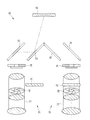
図3に示すように、3Dカメラ10の撮像ユニット30は、縦方向(第1の方向)に偏光軸を有する第1偏光板31が挿脱自在に設けられた撮影レンズ12と2枚のミラー32とから構成される第1撮影光学系33と、第1撮影光学系33の光路を開閉する第1シャッタ34と、前記縦方向と直交する横方向(第2の方向)に偏光軸を有する第2偏光板35が設けられた撮影レンズ13と2枚のミラー36とから構成される第2撮影光学系37と、第2撮影光学系37の光路を開閉する第2シャッタ38と、前記第1撮影光学系33と前記第2撮影光学系37のそれぞれの被写体像が同時に結像されるCCD(撮像素子)40と、から構成される。前記撮影レンズ12,13には絞り装置64が設けられている。
As shown in FIG. 3, the
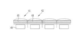
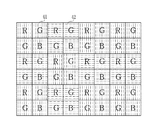
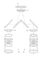
図4に示すように、CCD40は、縦方向に偏光軸を有する偏光板43と横方向に偏光軸を有する偏光板44が市松配列され、図5に示すように、第1受光素子41はフォトダイオード45の前に偏光板43が設けられ、第2受光素子42はフォトダイオード45の前に偏光板44が設けられている。図6に示すように、第1受光素子41は全て偏光板43を備え、正方格子状にベイヤー配列されている。また、図7に示すように、第2受光素子42は全て偏光板44を備え、正方格子状にベイヤー配列されている。前記第1受光素子及び前記第2受光素子は、互いに斜め45°に半ピッチ分ずれて配置され、全体として図4に示す市松配列となっている。
As shown in FIG. 4, in the
図8に示すように、前記CCD40は、ベイヤー配列された4つ1組の第1受光素子と、同じくベイヤー配列された4つ1組の第2受光素子とを、1組単位で交互に格子状に配列したものであっても良い。
As shown in FIG. 8, the
図3に戻って説明する。撮影モード選択ボタン24によって立体撮影モードが選択された場合は、前記第1撮影光学系33に前記第1偏光板31が挿入された状態で、第1シャッタ34と第2シャッタ38が開閉して、前記第1撮影光学系33と前記第2撮影光学系37による被写体像がともにCCD40に結像される。前記第1撮影光学系33による撮影光は前記第1受光素子41のみが受光し、前記第2シャッタ38による撮影光は前記第2受光素子42のみが受光する。
Returning to FIG. When the stereoscopic shooting mode is selected by the shooting
図9に示すように、通常撮影モードが選択された場合は、前記第1シャッタ34のみが開閉駆動され前記第2シャッタ38は駆動されず、前記第1撮影光学系33のみによる撮影が行われる。このときの第1撮影光学系33は光路上から前記第1偏光板31が退避した状態となっているため、第1撮影光学系33による撮影光はCCD40の第1受光素子41と第2受光素子42の両方で受光される。
As shown in FIG. 9, when the normal shooting mode is selected, only the
図10に示すように、3Dカメラ10の電気的構成は、前記CCD40、CPU50、CDS(相関二重サンプリング回路)51、AMP(増幅回路)52、A/D変換器53、画像信号処理回路54、圧縮伸長処理回路55、AE/AF処理回路(オートフォーカス手段)56、ROM57、RAM58、SDRAM59、前記LCDパネル18を制御するLCDドライバ61及びメディアコントローラ62がデータバス60に接続されている。CPU50は、ROM57に記憶されたシーケンスプログラムをワークメモリであるRAM58に読み出して実行する。CCD40から出力された撮像信号は、CDS51に入力され、CCD40の各受光素子の蓄積電荷量に正確に対応したR(赤)、G(緑)、B(青)の画像データとして出力される。CDS51から出力された画像データは、AMP52で増幅され、A/D変換器53でデジタルの画像データに変換される。A/D変換器53から出力された画像データは、データバス60を介してSDRAM59に一時的にストアされる。画像信号処理回路54は、SDRAM59から画像データを読み出して、階調変換、γ補正処理などの各種画像処理を施し、この画像データを再度SDRAM59に記録する。SDRAM59に一時的に格納された画像データは、LCDドライバ61でアナログのコンポジット信号に変換され、LCDパネル18に表示される。SDRAM59には、複数の画像を記憶する複数のメモリエリアがあり、一方からの読み出し中に、他方に書き込みをすることができる。圧縮伸長処理回路55は、画像信号処理回路54で画像処理が施された画像データに対して、所定の圧縮形式(例えばJPEG形式)で画像圧縮を施す。圧縮された画像データは、メディアコントローラ62を経由してメモリカード27に記憶される。
As shown in FIG. 10, the electrical configuration of the
CPU50には、前記撮影レンズ12,13のピント調節やズーミングを行うステッピングモータ(図示せず)を制御するモータドライバ63と、前記撮影レンズ12,13に組込まれた絞り装置64を制御する絞りドライバ65と、前記第1偏光板31を光路上に挿脱する偏光板駆動装置66と、前記第1及び第2シャッタ34,38を開閉制御するシャッタドライバ67と、前記ストロボ発光部14の発光を制御するストロボ回路68が接続されている。また、前記シャッタボタン17及び撮影モード選択ボタン24の操作信号がCPU50に入力される。撮像レンズ12,13は、背後に配置されたCCD40の受光面に被写体像を結像させる。CCD40に結像された画像のピントが合っているか否かはAE/AF処理回路56によって検知され、ピントが合っていない場合は、CPU50からモータドライバ63に指令がでて撮像レンズ12,13のピント合わせが行われる。この時、ピント位置が立体撮影に適した近距離範囲内か、立体撮影に適さない遠距離かが確認される。前記撮影モード選択ボタン24によって立体撮影モードが選択されているときに被写体位置が立体撮影に適さない遠距離であることが確認された場合は、CPU50から通常撮影モードに変更する指示が出され、自動的に通常撮影モードに設定される。
The
次に、図11に示すフローチャートに沿って、本発明による3Dカメラ10による立体画像を形成する左右2つの画像データを生成するための撮影手順及び作用について説明する。電源ボタン16をオンにして撮影再生切替ボタン20で撮影モードを選択し、撮影モード選択ボタン24を押して立体撮影モードに設定する。メカニカルシャッタである前記第1シャッタ34と第2シャッタ38は前記電源ボタン16のオンによって開く。被写体からの光が前記第1及び第2撮影光学系33,37によってCCD40へ結像され、結像された画像は定期的に取り込まれLCDパネルにスルー画として表示される。スルー画及びその表示についての説明は省略する。被写体像がCCD40に結像されるとAE/AF処理回路56によって第1及び第2撮影レンズ12,13のピント位置の計測が行われ、立体画像に適した近距離範囲と立体画像に適さない遠距離範囲を分けた閾値との比較が行われる。計測された値が閾値より小さい近距離範囲を示した場合は、第1及び第2偏光板31,35がそれぞれの光路上に挿入されていることが確認され、挿入されていないときは挿入される。その後、シャッタボタン17の押下によるレリーズ信号が発生するまで待機状態となる。一方、計測された値が閾値より大きい遠距離範囲を示した場合は、CPU50から切替信号が出力され自動的に通常撮影モードに移行される。通常撮影モードに移行されたことは、LCDパネル18に表示される。あるいは、自動的に通常撮影モードに移行されるのではなく、移行した方が良い旨のメッセージをLCD18パネルに表示して、通常撮影モードを選択するよう撮影者に注意を促す方法であっても良い。
Next, according to the flowchart shown in FIG. 11, the imaging procedure and operation for generating two left and right image data for forming a stereoscopic image by the
シャッタボタン17が押圧操作されると新たにCCD40への画像光の蓄積が開始され、所定時間経過後にCPU50の指示によって前記第1シャッタ34と第2シャッタ38が閉じられる(図12参照)。その後、CCD40から画像の読み出しが開始され、所定時間後に終了される。前記第1撮影光学系33を通過する光は偏光板31によって縦方向に偏光されているので、同じ縦方向の偏光板43が設けられた第1受光素子41には電荷が蓄積されるが、横方向の偏光板44が設けられた第2受光素子42には電荷が蓄積されない。同様に、前記第2撮影光学系37通過する光は偏光板35によって横方向に偏光されているので、同じ横方向の偏光板44が設けられた第2受光素子42には電荷が蓄積されるが、縦方向の偏光板43が設けられた第1受光素子41には電荷が蓄積されない。これによって、前記第1撮影光学系33による被写体画像は第1受光素子41にのみ蓄積され、前記第2撮影光学系37による被写体画像は第2受光素子42にのみ蓄積されることとなる。第1受光素子41と第2受光素子42からの画像の読み出しは別々に行われ、別の画像としてSDRAM59に保存される。このように同時に撮影された前記2つの撮影光学系33,37による被写体画像は1つのCCD40に結像され電荷が取り込まれるが、電荷の取り出しは別々に行われ別の画像として保存される。
When the
次に、図13に示すフローチャートに沿って、通常撮影モードが選択された場合について説明する。立体撮影モードと共通する部分の説明は一部省略する。通常撮影モードが選択されると、第1シャッタ34の開きが確認されるとともに、第2シャッタ38は閉じられる。続いて、第1偏光板31が撮影レンズ12の光路上から退避され、退避されていないときは退避位置に移動される。被写体からの光は第1撮影光学系33によってのみCCD40へ結像される。シャッタボタン17が押圧操作されると新たにCCD40への画像光の蓄積が開始され、所定時間経過後に第1シャッタ34が閉じられる。前記第1撮影光学系33を通過する光は偏光板を通過していないので第1受光素子41と第2受光素子42の両方に電荷が蓄積される。その後、全受光素子から画像の読み出しが開始され、所定時間後に終了される。これによって、通常撮影モードでは、立体撮影モードに比べて2倍の画素による画像データとなり、高画質な画像を得ることができる。
Next, a case where the normal shooting mode is selected will be described with reference to the flowchart shown in FIG. A part of the description common to the stereoscopic shooting mode is omitted. When the normal shooting mode is selected, the opening of the
前記実施形態は、第1受光素子と第2受光素子とを斜め45°に半ピッチずらして全体として市松配列したCCD40、あるいは第1受光素子と第2受光素子とをそれぞれ4つ1組にして1組単位で交互に格子状に配列したCCDを用いたが、これに限るものではなく、フォトダイオード45の半数を色のない輝度情報のみを取得する輝度ダイオードとし、残りをベイヤー配列としても良いし、4つ1組の構成を赤、緑、青と輝度ダイオードとしても良い。
In the embodiment, the
前記実施形態は、CCD40への画像光の蓄積が所定量となった時に、第1シャッタ34と第2シャッタ38を同時に閉じて2つの光学系による露光量を同じにしたが、図14に示すように、CCD40の直前に第3シャッタ71を設け、第3シャッタ71を閉じることで適性露光量とするようにしても良い。この場合、第1シャッタ34を省略しても問題ない。
In the above embodiment, when the accumulation of image light in the
前記実施形態は、第2撮影光学系37の偏光板35は固定としたが、偏光板31同様に光路に対して進退自在に設けても良い。また、絞り装置64は必ず設けなければならないものではなく、設けなくても問題ない。
In the above-described embodiment, the
10 3Dカメラ(撮像装置)
12,13 撮影レンズ
24 撮影モード選択ボタン(撮影撮影モード選択手段)
30 撮像ユニット
31 第1偏光板
32,36 ミラー
33 第1撮影光学系
34 第1シャッタ
35 第2偏光板
37 第2撮影光学系
38 第2シャッタ
40 CCD(撮像素子)
41 第1受光素子
42 第2受光素子
43,44 偏光板
45 フォトダイオード
50 CPU
56 AE/AF処理回路(オーフォーカス手段)
71 第3シャッタ
10 3D camera (imaging device)
12, 13
DESCRIPTION OF
41 1st
56 AE / AF processing circuit (autofocus means)
71 Third shutter
Claims (7)
前記第1の方向と直交する第2の方向に偏光軸を有する第2偏光板が光路上に設けられた第2撮影光学系と、
第1の方向に偏光軸を有する偏光板が設けられた第1受光素子と第2の方向に偏光軸を有する偏光板が設けられた第2受光素子とが同数づつ交互に格子状に配列され、前記第1撮影光学系と前記第2撮影光学系のそれぞれの被写体像が同時に結像される撮像素子と、を備え、
前記撮像素子から画像データを読み出して立体画像を形成する左右2つの画像データを生成することを特徴とする撮像装置。 A first imaging optical system in which a first polarizing plate having a polarization axis in a first direction is provided on the optical path;
A second imaging optical system in which a second polarizing plate having a polarization axis in a second direction orthogonal to the first direction is provided on the optical path;
The same number of first light receiving elements provided with polarizing plates having polarization axes in the first direction and second light receiving elements provided with polarizing plates having polarization axes in the second direction are alternately arranged in a lattice pattern. An imaging element on which subject images of the first imaging optical system and the second imaging optical system are simultaneously formed,
An image pickup apparatus that reads out image data from the image pickup device and generates left and right image data forming a stereoscopic image.
前記撮影モード選択手段によって前記通常撮影モードが選択された場合には、前記第1偏光板が前記第1撮影光学系の光路上から退避するとともに前記第2シャッタが前記第2撮影光学系の光路を遮光する位置で保持された状態で、被写体像の撮影が行われることを特徴とする請求項1乃至3いずれか記載の撮像装置。 Shooting mode selection means that can select either the stereoscopic shooting mode or the normal shooting mode, a first shutter that opens and closes the optical path of the first shooting optical system, and a second shutter that opens and closes the optical path of the second shooting optical system And the first polarizing plate is provided so as to freely advance and retract on the optical path of the first photographing optical system,
When the normal photographing mode is selected by the photographing mode selecting means, the first polarizing plate is retracted from the optical path of the first photographing optical system and the second shutter is an optical path of the second photographing optical system. The imaging apparatus according to claim 1, wherein a subject image is captured in a state where the image is held at a position where the light is shielded.
4. The image pickup apparatus according to claim 1, wherein the first shutter and the second shutter are controlled to be opened and closed at the same timing to shoot a subject image.
Priority Applications (1)
| Application Number | Priority Date | Filing Date | Title |
|---|---|---|---|
| JP2008219544A JP2010056865A (en) | 2008-08-28 | 2008-08-28 | Image capturing apparatus |
Applications Claiming Priority (1)
| Application Number | Priority Date | Filing Date | Title |
|---|---|---|---|
| JP2008219544A JP2010056865A (en) | 2008-08-28 | 2008-08-28 | Image capturing apparatus |
Publications (1)
| Publication Number | Publication Date |
|---|---|
| JP2010056865A true JP2010056865A (en) | 2010-03-11 |
Family
ID=42072315
Family Applications (1)
| Application Number | Title | Priority Date | Filing Date |
|---|---|---|---|
| JP2008219544A Pending JP2010056865A (en) | 2008-08-28 | 2008-08-28 | Image capturing apparatus |
Country Status (1)
| Country | Link |
|---|---|
| JP (1) | JP2010056865A (en) |
Cited By (17)
| Publication number | Priority date | Publication date | Assignee | Title |
|---|---|---|---|---|
| KR101082047B1 (en) | 2010-06-30 | 2011-11-10 | 엘지이노텍 주식회사 | 3-dimensional camera module having x-prism and using method thereof |
| US20110315863A1 (en) * | 2010-06-29 | 2011-12-29 | Hon Hai Precision Industry Co., Ltd. | Three-dimensional image capturing device |
| JP2012010095A (en) * | 2010-06-24 | 2012-01-12 | Panasonic Corp | Imaging device, and image processing method |
| WO2012056653A1 (en) * | 2010-10-26 | 2012-05-03 | パナソニック株式会社 | Lens unit |
| WO2012091199A1 (en) * | 2010-12-29 | 2012-07-05 | (주)스튜디오 로프트 | 3d viewer |
| JP2012150341A (en) * | 2011-01-20 | 2012-08-09 | Koptic Inc | Three-dimensional photographing camera |
| JP2012170026A (en) * | 2011-02-17 | 2012-09-06 | Sony Corp | Imaging apparatus, image processing method and program |
| WO2012161225A1 (en) * | 2011-05-24 | 2012-11-29 | ソニー株式会社 | Solid-state imaging element and camera system |
| WO2012169301A1 (en) * | 2011-06-06 | 2012-12-13 | 富士フイルム株式会社 | Image pickup device imaging three-dimensional moving image and two-dimensional moving image, and image pickup apparatus mounting image pickup device |
| CN103026295A (en) * | 2010-08-06 | 2013-04-03 | 松下电器产业株式会社 | Lense unit |
| CN103033940A (en) * | 2011-09-30 | 2013-04-10 | 索尼公司 | Imaging apparatus and imaging method |
| CN103324022A (en) * | 2012-03-19 | 2013-09-25 | 宏达国际电子股份有限公司 | 3D camera module and handheld device |
| WO2014017409A1 (en) * | 2012-07-23 | 2014-01-30 | Ricoh Company, Ltd. | Stereo camera |
| US8830605B2 (en) | 2010-10-26 | 2014-09-09 | Panasonic Corporation | Lens unit |
| EP2693756A4 (en) * | 2011-03-29 | 2015-05-06 | Sony Corp | Image pickup apparatus, image pickup device, image processing method, aperture control method, and program |
| EP2579568A4 (en) * | 2010-05-28 | 2016-03-16 | Sony Corp | Imaging device and imaging method |
| US11283985B2 (en) * | 2018-12-05 | 2022-03-22 | Gentex Corporation | Imaging system for iris authentication and driver monitoring |
-
2008
- 2008-08-28 JP JP2008219544A patent/JP2010056865A/en active Pending
Cited By (29)
| Publication number | Priority date | Publication date | Assignee | Title |
|---|---|---|---|---|
| EP2579568A4 (en) * | 2010-05-28 | 2016-03-16 | Sony Corp | Imaging device and imaging method |
| JP2012010095A (en) * | 2010-06-24 | 2012-01-12 | Panasonic Corp | Imaging device, and image processing method |
| US20110315863A1 (en) * | 2010-06-29 | 2011-12-29 | Hon Hai Precision Industry Co., Ltd. | Three-dimensional image capturing device |
| US8629388B2 (en) * | 2010-06-29 | 2014-01-14 | Hon Hai Precision Industry Co., Ltd. | Three-dimensional image capturing device |
| WO2012002661A2 (en) * | 2010-06-30 | 2012-01-05 | Lg Innotek Co., Ltd. | 3-dimensional camera module having x-prism and using method thereof |
| KR101082047B1 (en) | 2010-06-30 | 2011-11-10 | 엘지이노텍 주식회사 | 3-dimensional camera module having x-prism and using method thereof |
| WO2012002661A3 (en) * | 2010-06-30 | 2012-03-29 | Lg Innotek Co., Ltd. | 3-dimensional camera module having x-prism and using method thereof |
| US9118900B2 (en) | 2010-06-30 | 2015-08-25 | Lg Innotek Co., Ltd. | 3-dimensional camera module having X-prism and using method thereof |
| CN103026295A (en) * | 2010-08-06 | 2013-04-03 | 松下电器产业株式会社 | Lense unit |
| WO2012056653A1 (en) * | 2010-10-26 | 2012-05-03 | パナソニック株式会社 | Lens unit |
| US8830605B2 (en) | 2010-10-26 | 2014-09-09 | Panasonic Corporation | Lens unit |
| WO2012091199A1 (en) * | 2010-12-29 | 2012-07-05 | (주)스튜디오 로프트 | 3d viewer |
| JP2012150341A (en) * | 2011-01-20 | 2012-08-09 | Koptic Inc | Three-dimensional photographing camera |
| JP2012170026A (en) * | 2011-02-17 | 2012-09-06 | Sony Corp | Imaging apparatus, image processing method and program |
| EP2693756A4 (en) * | 2011-03-29 | 2015-05-06 | Sony Corp | Image pickup apparatus, image pickup device, image processing method, aperture control method, and program |
| US10397547B2 (en) | 2011-03-29 | 2019-08-27 | Sony Corporation | Stereoscopic image pickup unit, image pickup device, picture processing method, control method, and program utilizing diaphragm to form pair of apertures |
| US9544571B2 (en) | 2011-03-29 | 2017-01-10 | Sony Corporation | Image pickup unit, image pickup device, picture processing method, diaphragm control method, and program |
| US9826215B2 (en) | 2011-03-29 | 2017-11-21 | Sony Corporation | Stereoscopic image pickup unit, image pickup device, picture processing method, control method, and program utilizing diaphragm to form pair of apertures |
| US10728477B2 (en) | 2011-05-24 | 2020-07-28 | Sony Semiconductor Solutions Corporation | Solid-state image pickup device and camera system |
| US10104324B2 (en) | 2011-05-24 | 2018-10-16 | Sony Semiconductor Solutions Corporation | Solid-state image pickup device and camera system |
| WO2012161225A1 (en) * | 2011-05-24 | 2012-11-29 | ソニー株式会社 | Solid-state imaging element and camera system |
| WO2012169301A1 (en) * | 2011-06-06 | 2012-12-13 | 富士フイルム株式会社 | Image pickup device imaging three-dimensional moving image and two-dimensional moving image, and image pickup apparatus mounting image pickup device |
| JP2013077935A (en) * | 2011-09-30 | 2013-04-25 | Sony Corp | Imaging apparatus and imaging method |
| CN103033940A (en) * | 2011-09-30 | 2013-04-10 | 索尼公司 | Imaging apparatus and imaging method |
| US9784984B2 (en) | 2011-09-30 | 2017-10-10 | Sony Corporation | Imaging apparatus and imaging method |
| CN103324022A (en) * | 2012-03-19 | 2013-09-25 | 宏达国际电子股份有限公司 | 3D camera module and handheld device |
| US9348211B2 (en) | 2012-03-19 | 2016-05-24 | Htc Corporation | Camera module and portable device using the same |
| WO2014017409A1 (en) * | 2012-07-23 | 2014-01-30 | Ricoh Company, Ltd. | Stereo camera |
| US11283985B2 (en) * | 2018-12-05 | 2022-03-22 | Gentex Corporation | Imaging system for iris authentication and driver monitoring |
Similar Documents
| Publication | Publication Date | Title |
|---|---|---|
| JP2010056865A (en) | Image capturing apparatus | |
| US7856181B2 (en) | Stereoscopic imaging device | |
| US9077976B2 (en) | Single-eye stereoscopic image capturing device | |
| JP5722975B2 (en) | Imaging device, shading correction method for imaging device, and program for imaging device | |
| US20110018970A1 (en) | Compound-eye imaging apparatus | |
| TWI514847B (en) | Image processing device, image processing method, and recording medium | |
| JP5096048B2 (en) | Imaging apparatus, stereoscopic image reproduction apparatus, and stereoscopic image reproduction program | |
| JP5415170B2 (en) | Compound eye imaging device | |
| JP4764854B2 (en) | Imaging apparatus, image reproducing apparatus, imaging method, system, and program | |
| JP5426262B2 (en) | Compound eye imaging device | |
| US20110050856A1 (en) | Stereoscopic imaging apparatus | |
| JP5231771B2 (en) | Stereo imaging device | |
| JP4763827B2 (en) | Stereoscopic image display device, compound eye imaging device, and stereoscopic image display program | |
| JP2011075675A (en) | Compound-eye imaging apparatus | |
| JP2011087128A (en) | Pantoscopic camera and method for discrimination of object | |
| JP4730616B2 (en) | Compound eye digital camera | |
| JP2010154310A (en) | Compound-eye camera, and photographing method | |
| JP2010237582A (en) | Three-dimensional imaging apparatus and three-dimensional imaging method | |
| JP2010103949A (en) | Apparatus, method and program for photographing | |
| JP2007225897A (en) | Focusing position determination device and method | |
| JP5366693B2 (en) | IMAGING DEVICE, IMAGING DEVICE CONTROL METHOD, AND COMPUTER PROGRAM | |
| JP2010204385A (en) | Stereoscopic imaging apparatus and method | |
| JP5351298B2 (en) | Compound eye imaging device | |
| JP5054214B2 (en) | Compound eye digital camera | |
| JP5015340B2 (en) | Compound eye imaging device |