JP2010054836A - Image forming apparatus and process cartridge - Google Patents
Image forming apparatus and process cartridge Download PDFInfo
- Publication number
- JP2010054836A JP2010054836A JP2008220077A JP2008220077A JP2010054836A JP 2010054836 A JP2010054836 A JP 2010054836A JP 2008220077 A JP2008220077 A JP 2008220077A JP 2008220077 A JP2008220077 A JP 2008220077A JP 2010054836 A JP2010054836 A JP 2010054836A
- Authority
- JP
- Japan
- Prior art keywords
- process cartridge
- image forming
- photoconductor
- forming apparatus
- protective
- Prior art date
- Legal status (The legal status is an assumption and is not a legal conclusion. Google has not performed a legal analysis and makes no representation as to the accuracy of the status listed.)
- Granted
Links
- 238000000034 method Methods 0.000 title claims abstract description 186
- 108091008695 photoreceptors Proteins 0.000 claims abstract description 13
- 230000001681 protective effect Effects 0.000 claims description 101
- 238000011144 upstream manufacturing Methods 0.000 claims description 6
- 230000002093 peripheral effect Effects 0.000 claims description 4
- 238000013459 approach Methods 0.000 claims 1
- 238000005192 partition Methods 0.000 description 36
- 230000033001 locomotion Effects 0.000 description 16
- 230000006835 compression Effects 0.000 description 11
- 238000007906 compression Methods 0.000 description 11
- 230000001105 regulatory effect Effects 0.000 description 9
- 238000000926 separation method Methods 0.000 description 4
- 238000010438 heat treatment Methods 0.000 description 3
- 238000003780 insertion Methods 0.000 description 2
- 230000037431 insertion Effects 0.000 description 2
- 239000011347 resin Substances 0.000 description 2
- 229920005989 resin Polymers 0.000 description 2
- 239000000969 carrier Substances 0.000 description 1
- 239000003086 colorant Substances 0.000 description 1
- 238000010586 diagram Methods 0.000 description 1
- 230000000694 effects Effects 0.000 description 1
Images


Abstract
Description
本発明は、カラーレーザプリンタなどの画像形成装置、およびその画像形成装置に装着されるプロセスカートリッジに関する。 The present invention relates to an image forming apparatus such as a color laser printer, and a process cartridge attached to the image forming apparatus.
電子写真方式のカラーレーザプリンタとして、イエロー、マゼンタ、シアン、ブラックの4色のトナーに対応して、4つの感光ドラムを備えるタンデム型カラーレーザプリンタが知られている。
このようなタンデム型カラーレーザプリンタとして、たとえば、装置本体に対して着脱可能な像担持体カートリッジに、複数の像担持体が相互に位置決めされて取り付けられているカラー画像形成装置が提案されている(たとえば、特許文献1参照。)。
As an electrophotographic color laser printer, a tandem type color laser printer having four photosensitive drums corresponding to yellow, magenta, cyan, and black toners is known.
As such a tandem color laser printer, for example, a color image forming apparatus is proposed in which a plurality of image carriers are positioned and attached to an image carrier cartridge that can be attached to and detached from the apparatus main body. (For example, refer to Patent Document 1).
一方、特許文献1のように、装置本体に対して着脱可能な像担持体カートリッジを備えている場合、像担持体カートリッジを取り外すときに、像担持体が露出するので、そのときには、像担持体を保護することが望ましい。
そこで、たとえば、感光ドラムを備えたプロセスカートリッジに、感光ドラムを保護するドラムカバーが設けられた画像形成装置が提案されている(たとえば、特許文献2参照。)。
In view of this, for example, an image forming apparatus in which a process cartridge having a photosensitive drum is provided with a drum cover for protecting the photosensitive drum has been proposed (see, for example, Patent Document 2).
しかるに、特許文献2に記載の構成では、プロセスカートリッジが装置本体内に装填されてから、ドラムカバーが大きく回動して開いている。
そのため、特許文献1に記載の像担持体カートリッジに、特許文献2に記載のドラムカバーを備えると、画像形成装置本体内に、ドラムカバーを開閉するための大きな空間が必要になるという不具合がある。
However, in the configuration described in Patent Document 2, after the process cartridge is loaded in the apparatus main body, the drum cover is largely rotated and opened.
Therefore, when the image carrier cartridge described in
そこで、本発明の目的は、コンパクトな構成で、感光体を保護することができる画像形成装置、および、その画像形成装置に装着されるプロセスカートリッジを提供することにある。 SUMMARY OF THE INVENTION An object of the present invention is to provide an image forming apparatus capable of protecting a photoconductor with a compact configuration, and a process cartridge attached to the image forming apparatus.
上記目的を達成するため、請求項1に記載の発明は、画像形成装置であり、画像形成装置本体と、前記画像形成装置本体に着脱自在に装着され、感光体を備えるプロセスカートリッジとを備え、前記プロセスカートリッジは、前記感光体を支持する筐体と、前記筐体に対して相対移動可能な保護部材とを備え、前記画像形成装置本体は、前記筐体を付勢する付勢手段を備え、前記付勢手段が前記筐体を付勢しているときには、前記保護部材は、前記付勢手段の付勢方向において、前記感光体に対して上流側に退避する退避位置に配置され、前記付勢手段が前記筐体に対する付勢を解除しているときには、前記保護部材は、前記付勢手段の付勢方向において、前記感光体に対して下流側に進出する進出位置に配置されることを特徴としている。
In order to achieve the above object, an invention according to
また、請求項2に記載の発明は、請求項1に記載の発明において、前記画像形成装置本体に着脱自在に装着され、前記プロセスカートリッジを装着するためのプロセスフレームを備え、前記保護部材は、前記プロセスカートリッジが前記プロセスフレームに装着されたときには、まず、前記進出位置に配置されることを特徴としている。
また、請求項3に記載の発明は、請求項2に記載の発明において、前記プロセスフレームは、前記付勢手段の付勢方向において、前記保護部材の下流側端部と当接する規制部を備えていることを特徴としている。
According to a second aspect of the present invention, in the first aspect of the present invention, the image forming apparatus main body includes a process frame that is detachably mounted on the main body of the image forming apparatus, and the process cartridge is mounted. When the process cartridge is mounted on the process frame, first, the process cartridge is arranged at the advanced position.
According to a third aspect of the present invention, in the second aspect of the present invention, the process frame includes a restricting portion that comes into contact with a downstream end portion of the protection member in a biasing direction of the biasing means. It is characterized by having.
また、請求項4に記載の発明は、請求項2または3に記載の発明において、前記プロセスカートリッジは、複数設けられており、並列配置するように、前記プロセスフレームに装着され、前記付勢手段は、各前記プロセスカートリッジの並列方向に沿って進退する進退部材と、前記進退部材の進退に対応して、前記筐体を前記付勢方向に沿って押圧または押圧解除する押圧部材とを備えていることを特徴としている。 According to a fourth aspect of the present invention, in the second or third aspect of the present invention, a plurality of the process cartridges are provided, and are mounted on the process frame so as to be arranged in parallel, and the urging means Includes an advancing / retreating member that advances / retreats along the parallel direction of the process cartridges, and a pressing member that presses / releases the casing along the biasing direction in response to the advance / retreat of the advance / retreat member. It is characterized by being.
また、請求項5に記載の発明は、請求項2ないし4のいずれかに記載の発明において、前記プロセスフレームには、前記付勢手段の付勢方向上流側に向かって開く位置決め溝が形成されており、前記付勢手段が前記筐体を付勢しているときには、前記感光体の長手方向両端の外周面が、前記位置決め溝と当接することにより、前記筐体が、前記付勢手段の付勢方向において、位置決めされることを特徴としている。 According to a fifth aspect of the present invention, in the invention according to any one of the second to fourth aspects, the process frame is formed with a positioning groove that opens toward the upstream side in the biasing direction of the biasing means. When the urging means urges the casing, the outer peripheral surfaces at both ends in the longitudinal direction of the photoconductor are in contact with the positioning grooves, so that the casing is It is characterized by being positioned in the urging direction.
また、請求項6に記載の発明は、請求項5に記載の発明において、前記進退部材は、前記押圧部材がすべての前記筐体を押圧し、すべての保護部材を前記退避位置に配置させる全退避位置と、前記押圧部材が複数の前記筐体のうち少なくとも1つを押圧し、それに対応する保護部材を前記退避位置に配置させるとともに、残りの前記筐体を押圧解除し、それらに対応する保護部材を前記進出位置に配置させる部分退避位置と、前記押圧部材がすべての前記筐体を押圧解除し、すべての保護部材を前記進出位置に配置させる全進出位置とに移動することを特徴としている。
Further, the invention according to
また、請求項7に記載の発明は、プロセスカートリッジであり、感光体と、前記感光体を支持する筐体と、前記感光体の長手方向に沿って延び、前記感光体を挟んで並列配置される少なくとも2つの保護部材とを備え、前記保護部材は、前記感光体の長手方向、および、前記保護部材の並列方向の両方と直交する方向において、前記感光体に対して相対移動可能であることを特徴としている。 The invention according to claim 7 is a process cartridge, and is arranged in parallel with a photoconductor, a casing for supporting the photoconductor, extending in a longitudinal direction of the photoconductor, and sandwiching the photoconductor. At least two protective members, and the protective member is movable relative to the photosensitive member in a direction orthogonal to both the longitudinal direction of the photosensitive member and the parallel direction of the protective member. It is characterized by.
また、請求項8に記載の発明は、請求項7に記載の発明において、前記感光体に対して一方側に隣接し、前記筐体に支持される現像ユニットを備え、前記感光体よりも一方側に配置される前記保護部材は、前記保護部材の移動方向において、前記現像ユニットと対向し、前記感光体よりも他方側に配置される前記保護部材は、前記保護部材の移動方向に沿って延びる第1壁と、前記第1壁から連続し、前記保護部材の並列方向において、一方側の前記保護部材に向かって延びる第2壁とを備え、前記感光体よりも一方側に配置される前記保護部材の、並列方向における長さは、前記感光体よりも他方側に配置される前記保護部材の、並列方向における長さよりも長いことを特徴としている。 According to an eighth aspect of the invention, there is provided a developing unit according to the seventh aspect of the invention, further comprising a developing unit that is adjacent to the one side of the photoconductor and supported by the casing, and is one side of the photoconductor. The protection member arranged on the side faces the developing unit in the movement direction of the protection member, and the protection member arranged on the other side of the photoconductor is along the movement direction of the protection member. A first wall extending from the first wall; and a second wall extending toward the protective member on one side in a parallel direction of the protective member, and disposed on one side of the photoconductor. The length of the protective member in the parallel direction is longer than the length of the protective member arranged on the other side of the photoconductor in the parallel direction.
また、請求項9に記載の発明は、請求項7または8に記載の発明において、前記保護部材が前記感光体に対して相対的に近づく方向において、前記保護部材の下流側面に弾性体を備えていることを特徴としている。
The invention according to claim 9 is the invention according to
請求項1に記載の発明によれば、プロセスカートリッジが画像形成装置本体から取り外されているときには、付勢手段による筐体に対する付勢が解除されているので、保護部材は、感光体に対して付勢手段の付勢方向下流側の進出位置に配置されている。
そのため、保護部材は、感光体を、付勢手段の付勢方向下流側から、保護することができる。
According to the first aspect of the present invention, when the process cartridge is detached from the image forming apparatus main body, the urging force applied to the housing by the urging means is released, so that the protection member is against the photosensitive member. It arrange | positions in the advance position of the energizing direction downstream of the energizing means.
Therefore, the protection member can protect the photosensitive member from the urging direction downstream side of the urging means.
また、プロセスカートリッジが画像形成装置本体に装着され、付勢手段が筐体を付勢しているときには、保護部材は、感光体に対して付勢手段の付勢方向上流側の退避位置に配置されている。
そのため、保護部材は、感光体を、付勢手段の付勢方向下流側から、露出させることができる。
Further, when the process cartridge is mounted on the image forming apparatus main body and the urging unit urges the housing, the protective member is disposed at the retracted position upstream of the urging direction of the urging unit with respect to the photosensitive member. Has been.
Therefore, the protection member can expose the photoconductor from the urging direction downstream side of the urging means.
その結果、付勢手段の付勢方向において、保護部材を感光体に対して進退させるだけで感光体を保護または露出させるので、画像形成装置本体に大きな空間を設けることを不要とすることができ、コンパクトな構成で、感光体を保護することができる。
請求項2に記載の発明によれば、保護部材は、プロセスカートリッジがプロセスフレームに装着されたときには、まず、進出位置に配置される。
As a result, in the biasing direction of the biasing means, the photosensitive member is protected or exposed only by moving the protective member forward and backward with respect to the photosensitive member, so that it is not necessary to provide a large space in the image forming apparatus main body. The photoreceptor can be protected with a compact configuration.
According to the second aspect of the present invention, when the process cartridge is mounted on the process frame, the protective member is first arranged at the advanced position.
そのため、プロセスカートリッジがプロセスフレームに装着された最初の段階において、感光体を確実に保護することができる。
請求項3に記載の発明によれば、プロセスフレームは、付勢手段の付勢方向において、保護部材の下流側端部と当接する規制部を備えている。
そのため、付勢手段が筐体を付勢しているときには、プロセスカートリッジの保護部材が、プロセスフレームの規制部に当接するので、保護部材の付勢方向下流側に向かう移動が、規制部により規制される。
Therefore, the photosensitive member can be reliably protected at the initial stage when the process cartridge is mounted on the process frame.
According to the third aspect of the present invention, the process frame includes the restricting portion that comes into contact with the downstream end portion of the protection member in the biasing direction of the biasing means.
For this reason, when the urging means urges the housing, the protective member of the process cartridge comes into contact with the restricting portion of the process frame, so that the movement of the protective member toward the downstream side in the urging direction is restricted by the restricting portion. Is done.
その結果、付勢手段により筐体を付勢することにより、保護部材を、付勢手段の付勢方向において、確実に、感光体に対して上流側に退避させることができる。
請求項4に記載の発明によれば、付勢手段は、複数のプロセスカートリッジの並列方向に沿って進退する進退部材と、進退部材の進退に対応して、各プロセスカートリッジの筐体を付勢方向に沿って押圧または押圧解除する押圧部材とを備えている。
As a result, by energizing the housing with the energizing means, the protective member can be reliably retracted upstream from the photoreceptor in the energizing direction of the energizing means.
According to the invention described in claim 4, the urging means urges the housing of each process cartridge in accordance with the advance / retreat member that advances / retreats along the parallel direction of the plurality of process cartridges and the advance / retreat member. And a pressing member for pressing or releasing the pressing along the direction.
そのため、押圧部材は、進退部材の進退に対応して、各プロセスカートリッジの筐体を押圧または押圧解除することができる。
その結果、付勢手段により、各プロセスカートリッジの保護部材を連動させて進退させることができる。
請求項5に記載の発明によれば、付勢手段が筐体を付勢しているときには、感光体の長手方向両端の外周面が、位置決め溝と当接する。
Therefore, the pressing member can press or release the housing of each process cartridge in accordance with the advance / retreat of the advance / retreat member.
As a result, the urging means can advance and retract the protection members of the process cartridges in conjunction with each other.
According to the fifth aspect of the present invention, when the urging means is urging the casing, the outer peripheral surfaces at both ends in the longitudinal direction of the photoreceptor are in contact with the positioning grooves.
そのため、付勢手段によって筐体を付勢しているときに、確実に、筐体を位置決めすることができる。
請求項6に記載の発明によれば、進退部材が全退避位置に移動したときには、押圧部材がすべての筐体を押圧し、すべての保護部材を退避位置に配置させる。
また、進退部材が部分退避位置に移動したときには、押圧部材が複数の筐体のうち少なくとも1つを押圧し、それに対応する保護部材を退避位置に配置させるとともに、残りの筐体を押圧解除し、それらに対応する保護部材を進出位置に配置させる。
Therefore, the housing can be surely positioned when the housing is urged by the urging means.
According to the sixth aspect of the present invention, when the advance / retreat member moves to the all retracted position, the pressing member presses all the housings and arranges all the protecting members at the retracted position.
Further, when the advance / retreat member moves to the partial retracted position, the pressing member presses at least one of the plurality of housings, and the corresponding protective member is disposed at the retracted position, and the remaining housings are released from being pressed. The protective members corresponding to them are arranged at the advanced position.
また、進退部材が全進出位置に移動したときには、押圧部材がすべての筐体を押圧解除し、すべての保護部材を進出位置に配置させる。
これにより、進退部材の全退避位置、部分退避位置および全進出位置への移動により、各保護部材を連動させて進退させ、画像形成装置を、全ての保護部材を退避させるモード、少なくとも1つの筐体に対応する保護部材を退避させ、残りの保護部材を進出させるモード、および、全ての保護部材を進出させるモードに切り替えることができる。
Further, when the advance / retreat member moves to the fully advanced position, the pressing member releases the press of all the casings and arranges all the protective members at the advanced position.
Accordingly, the movement of the advance / retreat member to the full retracted position, the partial retracted position, and the fully advanced position causes the respective protective members to advance and retract in an interlocked manner, so that the image forming apparatus retracts all the protective members, and at least one housing. It is possible to switch to a mode in which the protective member corresponding to the body is retracted and the remaining protective members are advanced, and a mode in which all the protective members are advanced.
その結果、筐体を付勢する付勢手段と、保護部材とを利用して、画像形成装置のモードを切り替えることができ、画像形成装置の装置構成を簡略化することができる。
請求項7に記載の発明によれば、保護部材は、感光体の長手方向に沿って延び、感光体を挟んで並列配置されている。
そのため、保護部材は、感光体の両側から、確実に、感光体を保護することができる。
As a result, the mode of the image forming apparatus can be switched using the urging means for urging the casing and the protection member, and the apparatus configuration of the image forming apparatus can be simplified.
According to the seventh aspect of the present invention, the protection members extend along the longitudinal direction of the photoconductor and are arranged in parallel with the photoconductor interposed therebetween.
Therefore, the protection member can reliably protect the photoconductor from both sides of the photoconductor.
また、保護部材は、感光体の長手方向、および、保護部材の並列方向の両方と直交する方向において、感光体に対して相対移動可能である。
そのため、感光体を筐体の外側へ配置するように、保護部材が動いたときには、2つの保護部材の間から感光体を露出させることができ、感光体を筐体の内側へ配置するように、保護部材が動いたときには、2つの保護部材によって感光体を保護することができる。
Further, the protection member is movable relative to the photoconductor in a direction orthogonal to both the longitudinal direction of the photoconductor and the parallel direction of the protection members.
Therefore, when the protective member moves so that the photoconductor is arranged outside the housing, the photoconductor can be exposed from between the two protective members, and the photoconductor is arranged inside the housing. When the protective member moves, the photosensitive member can be protected by the two protective members.
その結果、簡単な構成で、確実に、感光体を保護することができる。
請求項8に記載の発明によれば、感光体よりも他方側に配置される保護部材は、保護部材の移動方向に沿って延びる第1壁と、第1壁から連続し、保護部材の並列方向において、一方側の保護部材に向かって延びる第2壁とを備えている。
そのため、感光体よりも他方側に配置される保護部材は、第1壁により、保護部材の並列方向他方側において、感光体を保護することができ、第2壁により、保護部材の移動方向において、感光体を保護することができる。
As a result, the photoreceptor can be reliably protected with a simple configuration.
According to the eighth aspect of the present invention, the protective member disposed on the other side of the photoconductor is continuous with the first wall extending along the moving direction of the protective member and the first wall, and the protective members are arranged in parallel. And a second wall extending toward the protective member on one side.
Therefore, the protective member arranged on the other side of the photoconductor can protect the photoconductor on the other side in the parallel direction of the protective member by the first wall, and in the moving direction of the protective member by the second wall. The photoconductor can be protected.
また、感光体よりも一方側に配置される保護部材は、保護部材の移動方向において、現像ユニットと対向し、その並列方向における長さは、感光体よりも他方側に配置される保護部材の、並列方向における長さよりも長く形成されている。
そのため、感光体よりも一方側に配置される保護部材は、保護部材の並列方向一方側において、現像ユニットと対向する空間を利用して、感光体よりも他方側に配置される保護部材よりも長い並列方向長さで、感光体を保護することができる。
The protective member arranged on one side of the photoconductor is opposed to the developing unit in the moving direction of the protective member, and the length in the parallel direction of the protective member arranged on the other side of the photoconductor is It is formed longer than the length in the parallel direction.
For this reason, the protective member arranged on one side of the photoconductor uses a space facing the developing unit on one side in the parallel direction of the protective member, rather than the protective member arranged on the other side of the photoconductor. The photoconductor can be protected with a long length in the parallel direction.
その結果、保護部材の並列方向、および、保護部材の移動方向のいずれの方向においても、確実に、感光体を保護することができる。
請求項9に記載の発明によれば、保護部材は、保護部材が感光体に対して相対的に近づく方向において、その下流側面に弾性体を備えている。
そのため、保護部材を感光体に対して相対的に近づけるには、弾性体の弾性力に抗して保護部材を押圧する必要がある。すなわち、保護部材は、感光体に向かう方向に外力が加わらない限り、弾性体の弾性力により、感光体から離間し続ける。
As a result, the photoconductor can be reliably protected in both the parallel direction of the protective members and the moving direction of the protective members.
According to the ninth aspect of the present invention, the protective member includes the elastic body on the downstream side surface in the direction in which the protective member is relatively closer to the photosensitive member.
Therefore, in order to bring the protective member relatively close to the photoconductor, it is necessary to press the protective member against the elastic force of the elastic body. That is, the protective member continues to be separated from the photoconductor by the elastic force of the elastic body unless an external force is applied in the direction toward the photoconductor.
その結果、感光体が筐体の内側に配置されるので、確実に、感光体を保護することができる。 As a result, since the photoconductor is disposed inside the housing, the photoconductor can be reliably protected.
1.カラーレーザプリンタの全体構成
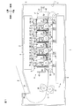
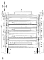
図1は、本発明の画像形成装置の一例としてのカラーレーザプリンタの一実施形態を示す側断面図である。
このカラーレーザプリンタ1は、横置きタイプのタンデム型カラーレーザプリンタであって、画像形成装置本体の一例としての本体ケーシング2内に、用紙Pを給紙するための給紙部3と、給紙された用紙Pに画像を形成するための画像形成部4とを備えている。
(1)本体ケーシング
本体ケーシング2は、画像形成部4を収容する側面視略矩形状のボックス状に形成されており、その一方側壁には、後述するプロセスフレーム12を着脱させるためのフロントカバー5が設けられている。
1. 1 is a side sectional view showing an embodiment of a color laser printer as an example of an image forming apparatus of the present invention.
The
(1) Main Body Casing The main body casing 2 is formed in a box shape having a substantially rectangular shape when viewed from the side for accommodating the image forming unit 4, and a
なお、以下の説明において、フロントカバー5が設けられる側(図1における右側)を前側とし、その反対側(図1における左側)を後側とする。また、カラーレーザプリンタ1を前側から見たときを左右の基準とする。すなわち、図1の紙面手前側が左側であり、紙面奥側が右側である。
(2)給紙部
給紙部3は、用紙Pを収容する給紙トレイ6を備えている。給紙トレイ6は、本体ケーシング2内の底部に着脱自在に装着されている。給紙トレイ6の前端部上方には、給紙ローラ7と、Uターンパスからなる給紙パス(図示せず)とが配置されている。
In the following description, the side where the
(2) Paper Feed Unit The
給紙ローラ7の回転により、給紙トレイ6に収容されている用紙Pが給紙パス(図示せず)に向けて1枚ずつ給紙される。その後、用紙Pは、給紙パス(図示せず)から、画像形成部4(感光ドラム19(後述)と搬送ベルト24(後述)との間)に向けて搬送される。
(3)画像形成部
画像形成部4は、スキャナ部8、プロセス部9、転写部10、および定着部11を備えている。
(3−1)スキャナ部
スキャナ部8は、本体ケーシング2の上部に配置されている。スキャナ部8は、鎖線で示すように、4つの感光ドラム19(後述)に向けて、画像データに基づくレーザビームをそれぞれ出射し、感光ドラム19(後述)を露光する。
(3−2)プロセス部
プロセス部9は、スキャナ部8の下方であって、給紙部3の上方に配置されており、1つのプロセスフレーム12と、各色に対応する4つのプロセスカートリッジ13とを備えている。
The paper P stored in the
(3) Image Forming Unit The image forming unit 4 includes a
(3-1) Scanner Unit The
(3-2) Process Unit The process unit 9 is disposed below the
プロセスフレーム12は、本体ケーシング2に、前後方向に沿って挿入または引き出し可能に装着されている。
プロセスカートリッジ13は、前後方向に沿って並列配置されるように、プロセスフレーム12に着脱自在に装着されている。具体的には、前側から後側に向かって、ブラックプロセスカートリッジ13K、イエロープロセスカートリッジ13Y、マゼンタプロセスカートリッジ13Mおよびシアンプロセスカートリッジ13Cが、順次配置されている。
(3−2−1)プロセスユニット
各プロセスカートリッジ13は、それぞれ、筐体の一例としてのプロセス筐体14を備えている。
The
The
(3-2-1) Process Unit Each
各プロセス筐体14は、左右1対のユニット側壁15と、両ユニット側壁15間に支持されるドラムユニット16および現像ユニット17とを備えている。
両ユニット側壁15は、側面視矩形状に形成され、左右方向に間隔を隔てて対向配置されている(図2参照。)。
ドラムユニット16は、両ユニット側壁15間の後側において、ドラム仕切壁18によって区画されており、感光体の一例としての感光ドラム19およびスコロトロン型帯電器(図示せず)を備えている。
Each process casing 14 includes a pair of left and right
Both
The
ドラム仕切壁18は、両ユニット側壁15間に架設され、前方下側が開放される閉断面矩形状に形成されている。
また、ドラム仕切壁18の後壁39は、その上側部分が、両ユニット側壁15の後端縁に沿って配置されており、その下側部分が、その上側部分から段差を経て両ユニット側壁15の後端縁よりも少し前方に配置されている。また、ドラム仕切壁18の後壁39の下端部は、両ユニット側壁15の下端部よりも上方に配置されている。
The
Further, the
感光ドラム19は、左右方向に沿って配置され、下方に向けて露出されるように、両ユニット側壁15の下端部において、回転自在に支持されている。より具体的には、感光ドラム19は、その上側半分部分の後側がドラム仕切壁18内に配置され、その上側半分部分の前側と下側半分部分とがドラム仕切壁18の開放部分から露出するように配置されている。また、感光ドラム19の下端部は、両ユニット側壁15の下端部よりも上方に配置されている。
The
また、感光ドラム19の両端は、両側のユニット側壁15よりも外側に突出しており、両側のユニット側壁15にそれぞれ設けられる円筒形状のカバー61によって被覆されている(図2参照)。
スコロトロン型帯電器(図示せず)は、感光ドラム19の斜め後側上方に、感光ドラム19と間隔を隔てて対向配置され、ドラム仕切壁18に支持されている。
Further, both ends of the
A scorotron charger (not shown) is disposed on the upper rear side of the
現像ユニット17は、両ユニット側壁15間の前側において、現像仕切壁20によって区画されており、現像ローラ21、供給ローラ(図示せず)および層厚規制ブレード(図示せず)を備えている。
現像仕切壁20は、両ユニット側壁15間に架設され、感光ドラム19に対向する下方後側が開放される閉断面矩形状に形成されている。
The developing
The developing
また、現像仕切壁20の前壁は、両ユニット側壁15の前端縁に沿って上下方向に延びるように配置されている。
また、現像仕切壁20の下壁40は、前後方向に延びる中央部分と、その中央部分から前壁に向けて、前方に向かうにつれ上方へ傾斜する傾斜部分とを備える断面視略V字形状に形成されている。現像仕切壁20の下壁40は、両ユニット側壁15の下端部およびドラム仕切壁18の下端部よりも上方に配置されている。
Further, the front wall of the developing
Further, the
現像ローラ21は、左右方向に沿って配置され、両ユニット側壁15において、回転自在に支持されている。現像ローラ21は、具体的には、その前側半分部分が、現像仕切壁20内に配置され、その後側半分部分が、現像仕切壁20の開放部分から露出するように配置されている。そして、現像ローラ21の露出部分が感光ドラム19の上側半分部分の前側と接触している。
The developing
供給ローラ(図示せず)は、現像仕切壁20内において、現像ローラ21の前側に配置され、両ユニット側壁15に回転自在に支持されている。
層厚規制ブレード(図示せず)は、現像ローラ21の上側に配置され、現像仕切壁20の後側に支持されている。
また、現像仕切壁20内の空間には、各色に対応するトナーが収容されている。
(3−2−2)プロセスユニットでの現像動作
現像仕切壁20内のトナーは、供給ローラ(図示せず)に供給され、さらに、現像ローラ21に供給され、供給ローラ(図示せず)と現像ローラ21との間で正極性に摩擦帯電される。
A supply roller (not shown) is disposed in front of the developing
The layer thickness regulating blade (not shown) is disposed on the upper side of the developing
Further, toner corresponding to each color is stored in the space in the developing
(3-2-2) Development Operation in Process Unit The toner in the
現像ローラ21に供給されたトナーは、現像ローラ21の回転に伴って、層厚規制ブレード(図示せず)によって厚さが規制され、一定厚さの薄層として現像ローラ21の表面に担持される。
一方、感光ドラム19の表面は、感光ドラム19の回転に伴って、スコロトロン型帯電器(図示せず)により一様に正帯電された後、ドラム仕切壁18と現像仕切壁20との間を通過するスキャナ部8からのレーザビーム(図1破線参照。)の高速走査により露光される。これにより、用紙Pに形成すべき画像に対応した静電潜像が感光ドラム19の表面に形成される。
The toner supplied to the developing
On the other hand, the surface of the
感光ドラム19がさらに回転すると、現像ローラ21の表面に担持され、かつ、正帯電されているトナーが、感光ドラム19の表面に形成されている静電潜像に供給される。これにより、感光ドラム19の静電潜像は可視像化され、感光ドラム19の表面には、反転現像によるトナー像が担持される。
(3−3)転写部
転写部10は、本体ケーシング2内において、給紙部3の上方であって、プロセス部9の下方において、前後方向に沿って配置されている。この転写部10は、駆動ローラ22、従動ローラ23、エンドレスベルトの一例としての搬送ベルト24および転写ローラ25を備えている。
When the
(3-3) Transfer Unit The
駆動ローラ22および従動ローラ23は、前後方向に間隔を隔てて対向配置されており、それらの周りに搬送ベルト24が巻回されている。
転写ローラ25は、各感光ドラム19と、搬送ベルト24を挟んで対向するように、それぞれ設けられている。
そして、給紙部3から給紙された用紙Pは、搬送ベルト24によって、前側から後側に向かって、各感光ドラム19と各転写ローラ25とが対向する転写位置を順次通過するように搬送される。その搬送中に、各感光ドラム19に担持されている各色のトナー像が、用紙Pに順次転写され、カラー画像が形成される。
(3−4)定着部
定着部11は、転写部10の後方に配置され、加熱ローラ26、および加熱ローラ26に対向する加圧ローラ27を備えている。転写部10において、用紙Pに転写されたカラー画像は、用紙Pが加熱ローラ26と加圧ローラ27との間を通過する間に、加熱および加圧されることによって用紙Pに熱定着される。
(4)排紙
トナー像が定着した用紙Pは、Uターンパスからなる排紙パス(図示せず)を通過して、排紙ローラ28に向けて搬送され、排紙ローラ28によって、本体ケーシング2の上面に形成された排紙トレイ29上に排紙される。
2.プロセス部の詳細
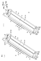
図2は、図1に示すプロセスカートリッジの斜視図であって、(a)は、保護部材が進出位置に配置されている状態を示し、(b)は、保護部材が退避位置に配置されている状態を示す。
The driving
The
The sheet P fed from the
(3-4) Fixing Unit The fixing
(4) Paper discharge The paper P on which the toner image has been fixed passes through a paper discharge path (not shown) consisting of a U-turn path and is conveyed toward the
2. 2 is a perspective view of the process cartridge shown in FIG. 1. FIG. 2A shows a state in which the protective member is disposed at the advanced position, and FIG. 2B shows a state in which the protective member is in the retracted position. Shows the state of being arranged.
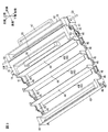
図3は、図2に示すプロセスカートリッジをプロセスフレームに装着する状態を示す斜視図である。
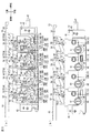
図4は、図2に示すプロセスカートリッジがプロセスフレームに装着された状態を説明する説明図であって、(a)は、断面図であり、(b)は、左側面図である。
(1)プロセスカートリッジの詳細
プロセスカートリッジ13では、上記したように、プロセス筐体の両ユニット側壁15間に、後側においてドラム仕切壁18が架設され、前側において、現像仕切壁20が架設されている。両ユニット側壁15は、ドラム仕切壁18の後壁39および現像仕切壁20の前壁よりも下方に長く形成されている。これによってプロセスカートリッジ13は、正面視において、略逆凹形状に形成されている。なお、現像仕切壁20の上壁には、プロセスカートリッジ13をプロセスフレーム12に着脱するときに、ユーザが把持するためのカートリッジ把持部70が設けられている。
FIG. 3 is a perspective view showing a state in which the process cartridge shown in FIG. 2 is attached to the process frame.
4A and 4B are explanatory views for explaining a state in which the process cartridge shown in FIG. 2 is mounted on the process frame. FIG. 4A is a cross-sectional view, and FIG. 4B is a left side view.
(1) Details of Process Cartridge In the
さらに、両ユニット側壁15間の下端部には、図2(a)に示すように、保護部材31が設けられている。
各ユニット側壁15の下端部には、図2(b)に示すように、その内面に、上下方向に沿って延びる側面視矩形状のガイド溝32が、感光ドラム19を挟むように前後方向に間隔を隔てて2つ形成されている(以下、ガイド溝32の前後関係に言及するときには、前側のガイド溝を前側ガイド溝32F、後側のガイド溝を後側ガイド溝32Rとする。)。
Further, a
As shown in FIG. 2B, a rectangular-shaped
前側ガイド溝32Fは、ユニット側壁15の前側において、ユニット側壁15の下端縁近傍から現像仕切壁20の下壁40近傍までの範囲に設けられている。
後側ガイド溝32Rは、ユニット側壁15の後側において、ユニット側壁15の下端縁近傍からドラム仕切壁18の後壁39近傍までの範囲に設けられている。
なお、前側ガイド溝32Fは、後側ガイド溝32Rよりも広幅に形成されている。
The
The
The
保護部材31は、感光ドラム19を挟むように2つ設けられており、前後方向に間隔を隔てて並列配置されている(以下、保護部材31の前後関係に言及するときには、前側の保護部材を前側保護部材31F、後側の保護部材を後側保護部材31Rとする。)。
前側保護部材31Fは、図4(a)に示すように、硬質の樹脂から、左右方向に沿って延び、現像仕切壁20の下壁40に対応する断面視V字形状に形成されており、上下方向において、現像仕切壁20の下壁40と対向している。詳しくは、前側保護部材31Fは、左右方向および前後方向に沿って延びる第1前側保護板34と、第1前側保護板34の前端縁から、前方に向かうにつれ上方に向かうように延びる第2前側保護板35とを一体的に備えている。
Two
As shown in FIG. 4A, the
後側保護部材31Rは、硬質の樹脂から、左右方向に沿って延びる断面視L字形状に形成されており、ドラム仕切壁18の後壁39と対向している。詳しくは、後側保護部材31Rは、左右方向および上下方向に沿って延びる第1壁の一例としての第1後側保護板36と、第1後側保護板36の下端縁から連続して、前方に向かって延びる第2壁の一例としての第2後側保護板37とを一体的に備えている。
The rear
なお、第1後側保護板36は、ドラム仕切壁18の後壁39の下側部分の後面に沿って配置され、その上側部分と上下方向において対向する。
また、前側保護部材31Fの前後方向長さL1は、後側保護部材31Rの前後方向長さL2よりも長く形成されている。
また、第1前側保護板34および第2後側保護板37には、その左右方向両端縁から左右方向外側に向かって突出する支持部33が、それぞれ一体的に設けられている(以下、支持部33の前後関係に言及するときには、前側の支持部を前側支持部33F、後側の支持部を後側支持部33Rとする。)。
The first
The front-rear direction length L1 of the
In addition, the first
各支持部33は、対応する各ガイド溝32の前後方向長さよりもやや短い前後方向長さの角柱形状に形成されている。
そして、前側保護部材31Fの前側支持部33Fが、ユニット側壁15の前側ガイド溝32Fにスライド自在に嵌合されることにより、前側保護部材31Fは、上下方向において、プロセス筐体14および感光ドラム19に対して相対移動可能に、プロセスカートリッジ13に備えられる。
Each
Then, the front
具体的には、前側保護部材31Fは、前側ガイド溝32Fに沿って、現像仕切壁20の下壁40と上下方向に対向した状態で、下壁40と近接する位置(感光ドラム19と近接する退避位置)(図7参照)と、ユニット側壁15の下端縁と近接する位置(感光ドラム19から離間する進出位置)(図4参照)とに移動する。
また、後側保護部材31Rの後側支持部33Rが、ユニット側壁15の後側ガイド溝32Rにスライド自在に嵌合されることにより、後側保護部材31Rは、上下方向において、プロセス筐体14および感光ドラム19に対して相対移動可能に、プロセスカートリッジ13に備えられる。
Specifically, the
Further, the rear
具体的には、後側保護部材31Rは、後側ガイド溝32Rに沿って、ドラム仕切壁18の後壁39と上下方向に対向した状態で、第2後側保護板37が後壁39の下面と近接する位置(感光ドラム19と近接する退避位置)(図7参照)と、第2後側保護板37がユニット側壁15の下端縁と近接する位置(感光ドラム19から離間する進出位置)(図4参照)とに移動する。
Specifically, the
また、図4(a)に示すように、第1前側保護板34の上面と、現像仕切壁20の下壁40の下面との間には、弾性体の一例としての前側圧縮バネ38Fが設けられている。
また、第2後側保護板37の上面と、ドラム仕切壁18の後壁39の下端面との間には、弾性体の一例としての後側圧縮バネ38Rが設けられている。
これにより、保護部材31は、常には、感光ドラム19に対して相対的に離間するように、下方に向かって付勢されている。
As shown in FIG. 4A, a
A
Thus, the
そして、保護部材31は、常には、圧縮バネ38の付勢力により、感光ドラム19に対して下方へ進出する進出位置(図2(a)参照。)に配置される。また、圧縮バネ38の付勢力に抗して、進出位置から、感光ドラム19に対して上方へ退避する退避位置(図2(b)参照。)へ移動する。
保護部材31は、進出位置では、感光ドラム19の下端縁よりも下方に配置される(図4(a)参照)。つまり、感光ドラム19は、保護部材31よりも内側に配置され、保護部材31によって保護される。また、保護部材31は、退避位置では、感光ドラム19の下端縁よりも上方に配置される(図7(a)参照)。つまり、感光ドラム19は、各保護部材31の間から露出される。
(2)プロセスフレームの詳細
プロセスフレーム12は、図3に示すように、4つのプロセスカートリッジ13を収容する枠状に形成され、左右1対のフレーム側壁41、フロントビーム42、リヤビーム43および複数のガイド板44を備えている。
The
The
(2) Details of Process Frame As shown in FIG. 3, the
1対のフレーム側壁41は、4つのプロセスカートリッジ13を左右方向に挟んで対向配置される。また、各フレーム側壁41には、各プロセスカートリッジ13と対向する位置において、その上端から下方に向かって切り欠かれる4つの切欠部45と、切欠部45の下端から下方に向かって切り欠かれる4つの位置決め溝46とが形成されている。
切欠部45は、感光ドラム19の両端およびカバー61を露出するような大きさで、側面視略矩形状に形成されている。
The pair of
The
位置決め溝46は、カバー61の外周面と当接するように、上側に向かって開く側面視略U字状に形成されている。
フロントビーム42は、左右方向に延びる断面視略U字状に形成され、各フレーム側壁41の前端部間に架設されている。フロントビーム42の前面には、プロセスフレーム12を本体ケーシング2に着脱するときに、ユーザが把持するためのフレーム把持部47が一体的に形成されている。
The
The
リヤビーム43は、左右方向に延びる断面視略U字状に形成され、各フレーム側壁41の後端部間に架設されている。
ガイド板44は、フロントビーム42とリヤビーム43との間において、等間隔を隔てて並列配置されるように、両フレーム側壁41間に3枚架設されている。また、ガイド板44は、左右方向および上下方向に延び、その左右方向両端部は、互いに隣り合う切欠部45の間において、両フレーム側壁41に連続している。
The
Three
これにより、フロントビーム42、リヤビーム43および左右1対のフレーム側壁41に囲まれる空間は、3枚のガイド板44により、前後方向に4等分されている。
また、各ガイド板44、フロントビーム42およびリヤビーム43の下端部には、プロセスカートリッジ13の保護部材31の下端面が当接する規制部の一例としての規制板48が、左右方向に沿って設けられている(以下、規制板48の前後関係に言及するときには、前側の規制板を前側規制板48F、後側の規制板を後側規制板48Rとする。)。
Thus, the space surrounded by the
In addition, a regulating
詳しくは、ガイド板44には、図4に示すように、その下端部から後方に向かって相対的に長く突出し、前側保護部材31Fの下面が当接する前側規制板48Fと、その下端部から前方に向かって相対的に短く突出し、後側保護部材31Rの下面が当接する後側規制板48Rとが設けられている。
また、フロントビーム42には、その下端部から後方に向かって相対的に長く突出し、前側保護部材31Fの下面が当接する前側規制板48Fが設けられている。
Specifically, as shown in FIG. 4, the
Further, the
また、リヤビーム43には、その下端部から前方に向かって相対的に短く突出し、後側保護部材31Rの下面が当接する後側規制板48Rが設けられている。
規制板48は、1対のフレーム側壁41との間に両ユニット側壁15を挿通可能な空間が隔てられている。また、前側規制板48Fと後側規制板48Rとの間には、感光ドラム19の下側部分を挿通可能な空間が隔てられている。
In addition, the
The
また、プロセスフレーム12の後端部には、第1ガイド軸49が、プロセスフレーム12の前端部には、第2ガイド軸50が、左右方向にわたって貫通されており、第1ガイド軸49および第2ガイド軸50の両端部は、両フレーム側壁41から左右方向外側に突出している。
3.本体ケーシングの詳細
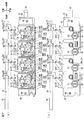
図5は、図4に示すプロセスフレームが本体ケーシングに装着された状態を説明する説明図であって、(a)は、断面図であり、(b)は、左側面図である。
A
3. Details of Main Body Casing FIG. 5 is an explanatory view for explaining a state where the process frame shown in FIG. 4 is mounted on the main body casing, wherein (a) is a sectional view and (b) is a left side view. is there.
図6は、図5に対応する正面図である。
本体ケーシング2の内部には、図5および図6に示すように、付勢手段の一例としての直動カム機構51が設けられている。
直動カム機構51は、進退部材の一例としての左右1対の直動カム52と、各色のプロセスカートリッジ13に対応する押圧部材の一例としての左右4対の揺動カム53とを備えている。
FIG. 6 is a front view corresponding to FIG.
As shown in FIGS. 5 and 6, a
The
1対の直動カム52は、前後方向に延びる角棒形状に形成されており、左右方向に間隔を隔てて対向配置されている。直動カム52は、本体ケーシング2の左右の本体側壁62の内側に配置され、本体側壁62に沿って配置されている。
また、直動カム52には、各揺動カム53に対応する4つの凹部54が形成されている。また、直動カム52は、ラックギヤ部55を備えている。
The pair of
The
凹部54は、直動カム52の下端縁から上方に向かって切り欠かれるように形成されており、前後方向に間隔を隔てて並列配置されている。また、最前側の凹部54は、それより後側の3つの凹部54よりも前後方向に長く形成されている。また、後側の3つの凹部54の前後方向長さは、互いに等しく形成されている。
ラックギヤ部55は、直動カム52の後端部において、直動カム52の上端縁に形成されている。
The
The
揺動カム53は、1つの直動カム52に対応して4つ設けられている。4つの揺動カム53は、互いに前後方向に間隔を隔てて、前方から順次、ブラックプロセスカートリッジ13K、イエロープロセスカートリッジ13Y、マゼンタプロセスカートリッジ13Mおよびシアンプロセスカートリッジ13Cに対応するように、並列配置されている。
また、揺動カム53は、前後方向略中央部分に揺動支点を有し、その前側に、直動カム52の凹部54に嵌合する鉤部56と、その後側に、プロセスカートリッジ13のユニット側壁15の上面に当接する当接アーム部57とを一体的に備えている。
Four
Further, the
鉤部56は、前端部が上方に向かって屈曲する側面視鉤形状に形成されている。
当接アーム部57は、鉤部56の後端部から連続して後方斜め下方に向かって延びる細長の平板形状に形成されている。
また、揺動カム53には、鉤部56と当接アーム部57との間に、支持軸挿通穴58が形成されている。
The
The
The
そして、支持軸挿通穴58に、本体ケーシング2の本体側壁62から内側に突出する支持軸59が挿通固定されることにより、揺動カム53は、支持軸59に対して揺動可能に支持される。
また、揺動カム53は、一端が揺動カム53に係止され、他端が本体側壁62に係止され、支持軸59に巻回される付勢バネ(図示せず)によって、常には、左側面視において反時計回りに付勢されている。
Then, the
Further, the
そして、直動カム52のラックギヤ部55に、図示しないギヤ列を介して、本体ケーシング2に設けられるモータ(図示せず)からの駆動力が入力されると、直動カム52は前後方向に往復移動する。
これにより、直動カム52は、最も前方の全進出位置(図5参照)と、最も後方の全退避位置(図7参照)と、全進出位置と全退避位置との間の部分退避位置(図8参照)との間を移動する。
When a driving force from a motor (not shown) provided in the main body casing 2 is input to the
As a result, the
まず、直動カム52が全進出位置に配置されているときには、全ての揺動カム53において、鉤部56が凹部54から外れて、直動カム52の下端縁に当接しており、当接アーム部57が、付勢バネ(図示せず)の付勢力に抗して上方に退避している(図5参照)。
そして、直動カム52が部分退避位置に配置されると、最前側の凹部54の後端部が、ブラックプロセスカートリッジ13Kに対応する揺動カム53の鉤部56と上下方向において対向する。すると、その揺動カム53が、付勢バネ(図示せず)の付勢力により反時計回りに揺動して、鉤部56が凹部54の後端部に嵌合し、同時に、当接アーム部57が下方に進出する(図8参照)。
First, when the
When the
そして、直動カム52が全退避位置に配置されると、ブラックプロセスカートリッジ13Kに対応する揺動カム53の鉤部56が、最前方の凹部54の前端部に配置され、残りの3つの揺動カム53の鉤部56と、残りの3つの揺動カム53に対応する凹部54とが上下方向において対向する。すると、残りの3つの揺動カム53が、付勢バネ(図示せず)の付勢力により反時計回りに揺動する。これにより、3つの揺動カム53において、鉤部56が凹部54に嵌合し、同時に、当接アーム部57が下方に進出する(図7参照)。
When the
また、本体ケーシング2には、本体側壁62において、前後方向に沿って延びるように、第1ガイド溝63および第2ガイド溝64が形成されている。
4.プロセスカートリッジの本体ケーシングへの装着動作
プロセスカートリッジ13を本体ケーシング2に装着するには、まず、プロセスフレーム12を引き出し、プロセスカートリッジ13をプロセスフレーム12に装着する。
In the main body casing 2, a
4). Mounting operation of process cartridge to main body casing In order to mount the
プロセスカートリッジ13をプロセスフレーム12に装着するには、図3に示すように、プロセスカートリッジ13の前端部および後端部がガイド板44に沿うように、かつ、カバー61が位置決め溝46に嵌合するように、位置を合わせて、上方からプロセスカートリッジ13をプロセスフレーム12へ挿入する。
すると、プロセスユニット13の保護部材31の下面が規制板48に当接して、プロセスユニット13がプロセスフレーム12に装着される。
To attach the
Then, the lower surface of the
次いで、本体ケーシング2にプロセスフレーム12を装着するには、本体ケーシング2に対して、後方に向かってプロセスフレーム12を押し込む。
すると、図6に示すように、プロセスフレーム12の第1ガイド軸49が、本体ケーシング2の第1ガイド溝63に嵌合し、プロセスフレーム12の第2ガイド軸50が、本体ケーシング2の第2ガイド溝64に嵌合して、後方に向かって案内されて、プロセスフレーム12が本体ケーシング2に装着される。
5.プロセスカートリッジの本体ケーシング内での動作
図7は、図5に示す直動カムが全退避位置に配置された状態を説明する説明図であって、(a)は、断面図であり、(b)は、左側面図である。
Next, in order to attach the
Then, as shown in FIG. 6, the
5). FIG. 7 is an explanatory view for explaining a state in which the linear cam shown in FIG. 5 is disposed at the fully retracted position, wherein (a) is a sectional view, (b) ) Is a left side view.
図8は、図5に示す直動カムが部分退避位置に配置された状態を説明する説明図であって、(a)は、断面図であり、(b)は、左側面図である。
プロセスフレーム12が本体ケーシング2に装着されると、図5および図6に示すように、揺動カム53の当接アーム部57が、対応するプロセスカートリッジ13の両ユニット側壁15と当接する。
8A and 8B are explanatory views for explaining a state in which the linear cam shown in FIG. 5 is disposed at the partial retracted position. FIG. 8A is a cross-sectional view, and FIG. 8B is a left side view.
When the
このとき、プロセスカートリッジ13の保護部材31は、プロセスフレーム12の規制板48と当接し、上下方向において位置固定されている。また、直動カム52は、全進出位置に配置されており、上述したように、全ての揺動カム53の当接アーム部57は、上方に退避している。すなわち、全ての揺動カム53は、プロセスカートリッジ13を押圧解除している。
At this time, the
そのため、全てのプロセスカートリッジ13のプロセス筐体14は、圧縮バネ38の付勢力によって、保護部材31に対して上方に退避している。つまり、全ての保護部材31は、感光ドラム19に対して、下方に進出する進出位置に配置されている。
これにより、カラーレーザプリンタ1は、全ての感光ドラム19が搬送ベルト24から離間する全離間モードになっている。
Therefore, the
As a result, the
次いで、直動カム52が後方に移動し、部分退避位置に配置されると、図8に示し、上述したように、ブラックプロセスカートリッジ13Kに対応する揺動カム53の当接アーム部57が下方に進出する。
すると、ブラックプロセスカートリッジ13Kのプロセス筐体14は、対応する揺動カム53によって、上方から下方に向かって押圧され、圧縮バネ38の付勢力に抗して、保護部材31に対して下方に向かって進出する。そして、このプロセス筐体14は、感光ドラム19の両端を被覆するカバー61が位置決め溝46と当接することにより、位置決めされる。
Next, when the
Then, the
すると、ブラックプロセスカートリッジ13Kの保護部材31は、感光ドラム19に対して、上方に退避する退避位置に配置される。
なお、ブラックプロセスカートリッジ13K以外のプロセスカートリッジ13に対応する揺動カム53は、ブラックプロセスカートリッジ13K以外のプロセスカートリッジ13を押圧解除している。そのため、ブラックプロセスカートリッジ13K以外のプロセスカートリッジ13のプロセス筐体14は、保護部材31に対して上方に退避し、それらの保護部材31は、感光ドラム19に対して、下方に進出する進出位置に配置されている。
Then, the
The
これにより、カラーレーザプリンタ1は、全離間モードから、ブラックプロセスカートリッジ13Kの感光ドラム19のみ搬送ベルト24に接触するブラック接触モードに移行する。そのため、ブラック接触モードでは、モノクロ画像が形成される。
次いで、直動カム52が最も後方に移動し、全退避位置に配置されると、図7に示し、上述したように、全ての揺動カム53の当接アーム部57が下方に進出する。
As a result, the
Next, when the
すると、全てのプロセス筐体14は、対応する揺動カム53によって、上方から下方に向かって押圧され、圧縮バネ38の付勢力に抗して、保護部材31に対して下方に向かって進出する。そして、全てのプロセス筐体14は、感光ドラム19の両端を被覆するカバー61が位置決め溝46と当接することにより、位置決めされる。
すると、全ての保護部材31は、感光ドラム19に対して、上方に退避する退避位置に配置される。
Then, all the
Then, all the
これにより、カラーレーザプリンタ1は、ブラック接触モードから、全ての感光ドラム19が搬送ベルト24に接触する全色接触モードに移行する。そのため、全色接触モードでは、カラー画像が形成される。
6.作用効果
(1)このカラーレーザプリンタ1によれば、図4(a)に示すように、プロセスカートリッジ13が本体ケーシング2から取り外されているときには、直動カム機構51の揺動カム53によるプロセス筐体14に対する付勢が解除されているので、保護部材31は、感光ドラム19に対して下方の進出位置に配置されている。
As a result, the
6). Operation and Effect (1) According to this
そのため、保護部材31は、感光ドラム19を、下側から、保護することができる。
また、プロセスカートリッジ13が本体ケーシング2に装着され、直動カム機構51の揺動カム53がプロセス筐体14を付勢しているときには、図7(a)に示すように、保護部材31は、感光ドラム19に対して上方の退避位置に配置されている。
そのため、保護部材31は、感光ドラム19を、下方から、露出させることができる。
Therefore, the
When the
Therefore, the
その結果、上下方向において、保護部材31を感光ドラム19に対して進退させるだけで感光ドラム19を保護または露出させるので、本体ケーシング2に大きな空間を設けることを不要とすることができ、コンパクトな構成で、感光ドラム19を保護することができる。
(2)このカラーレーザプリンタ1によれば、図5(a)に示すように、保護部材31は、プロセスカートリッジ13がプロセスフレーム12に装着されたときには、まず、進出位置に配置される。
As a result, in the vertical direction, the
(2) According to the
そのため、プロセスカートリッジ13がプロセスフレーム12に装着された最初の段階において、感光ドラム19を確実に保護することができる。
(3)このカラーレーザプリンタ1によれば、図3に示すように、プロセスフレーム12は、上下方向において、保護部材31の下面と当接する規制板48を備えている。
そのため、図7(a)に示すように、直動カム機構51の揺動カム53がプロセス筐体14を付勢しているときには、プロセスカートリッジ13の保護部材31が、プロセスフレーム12の規制板48に当接するので、保護部材31の下方に向かう移動が、規制板48により規制される。
Therefore, the
(3) According to the
Therefore, as shown in FIG. 7A, when the
その結果、直動カム機構51の揺動カム53によりプロセス筐体14を付勢することにより、保護部材31を、上下方向において、確実に、感光ドラム19に対して上方に退避させることができる。
(4)このカラーレーザプリンタ1によれば、図5(a)に示すように、直動カム機構51は、複数のプロセスカートリッジ13が並列する前後方向に沿って進退する直動カム52と、直動カム52の進退に対応して、各プロセスカートリッジ13のプロセス筐体14を上下方向に沿って押圧または押圧解除する揺動カム53とを備えている。
As a result, by energizing the process casing 14 by the
(4) According to this
そのため、揺動カム53は、直動カム52の進退に対応して、各プロセスカートリッジ13のプロセス筐体14を押圧または押圧解除することができる。
その結果、直動カム機構51により、各プロセスカートリッジ13の保護部材31を連動させて進退させることができる。
(5)このカラーレーザプリンタ1によれば、図7(a)に示すように、直動カム機構51の揺動カム53がプロセス筐体14を付勢しているときには、感光ドラム19の両端を被覆するカバー61が、位置決め溝46と当接する。
Therefore, the
As a result, the
(5) According to this
そのため、直動カム機構51の揺動カム53によってプロセス筐体14を付勢しているときに、確実に、プロセス筐体14を位置決めすることができる。
(6)このカラーレーザプリンタ1によれば、図7(a)に示すように、直動カム52が全退避位置に移動したときには、揺動カム53がすべてのプロセス筐体14を押圧し、すべての保護部材31を退避位置に配置させる。
Therefore, when the
(6) According to this
また、図8(a)に示すように、直動カム52が部分退避位置に移動したときには、揺動カム53がブラックプロセスカートリッジ13Kのプロセス筐体14を押圧し、それに対応する保護部材31を退避位置に配置させるとともに、残りの3つのプロセス筐体14を押圧解除し、それらに対応する保護部材31を進出位置に配置させる。
また、図5(a)に示すように、直動カム52が全進出位置に移動したときには、揺動カム53がすべてのプロセス筐体14を押圧解除し、すべての保護部材31を進出位置に配置させる。
Further, as shown in FIG. 8A, when the
Further, as shown in FIG. 5A, when the
これにより、直動カム52の全退避位置、部分退避位置および全進出位置への移動により、各保護部材31を連動させて進退させることができる。
そのため、カラーレーザプリンタ1を、全ての保護部材31を退避させ、全ての感光ドラム19と搬送ベルト24とを接触させる全色接触モード、ブラックプロセスカートリッジ13Kの保護部材31を退避させ、残りの3つの保護部材31を進出させて、ブラックプロセスカートリッジ13Kの感光ドラム19のみを搬送ベルト24と接触させるブラック接触モード、および、全ての保護部材31を進出させ、全ての感光ドラム19を搬送ベルト24から離間させる全離間モードに切り替えることができる。
Thereby, each
Therefore, in the
その結果、プロセス筐体14を付勢する直動カム機構51と、保護部材31とを利用して、カラーレーザプリンタ1のモードを切り替えることができ、カラーレーザプリンタ1の装置構成を簡略化することができる。
(7)このプロセスカートリッジ13によれば、図2に示すように、保護部材31は、感光ドラム19の軸線方向(左右方向)に沿って延び、感光ドラム19を挟んで並列配置されている。
As a result, the mode of the
(7) According to this
そのため、保護部材31は、感光ドラム19の両側から、確実に、感光ドラム19を保護することができる。
また、保護部材31は、上下方向において、感光ドラム19に対して相対移動可能である。
そのため、図2(b)に示すように、感光ドラム19をプロセス筐体14の外側へ配置するように、保護部材31が上方に向かって動いたときには、2つの保護部材31の間から感光ドラム19を露出させることができ、図2(a)に示すように、感光ドラム19をプロセス筐体14の内側へ配置するように、保護部材31が下方に向かって動いたときには、2つの保護部材31によって感光ドラム19を保護することができる。
Therefore, the
Further, the
Therefore, as shown in FIG. 2B, when the
その結果、簡単な構成で、確実に、感光ドラム19を保護することができる。
(8)このプロセスカートリッジ13によれば、図2(a)に示すように、感光ドラム19よりも後側に配置される後側保護部材31Rは、上下方向に沿って延びる第1後側保護板36と、第1後側保護板36から連続し、前方に向かって延びる第2後側保護板37とを備えている。
As a result, the
(8) According to the
そのため、後側保護部材31Rは、第1後側保護板36により、後側から感光ドラム19を保護することができ、第2後側保護板37により、下側から感光ドラム19を保護することができる。
また、感光ドラム19よりも前側に配置される前側保護部材31Fは、上下方向において、現像ユニット17と対向し、その前後方向長さL1は、後側保護部材31Rの、前後方向長さL2よりも長く形成されている。
Therefore, the rear
Further, the front
そのため、前側保護部材31Fは、前側において、現像ユニット17と対向する空間を利用して、後側保護部材31Rよりも長い前後方向長さで、感光ドラム19を保護することができる。
その結果、前後方向および下方のいずれの方向においても、確実に、感光ドラム19を保護することができる。
(9)このプロセスカートリッジ13によれば、図4(a)に示すように、保護部材31は、その上面に圧縮バネ38を備えている。
Therefore, the front
As a result, the
(9) According to this
そのため、保護部材31を感光ドラム19に対して相対的に近づけるには、圧縮バネ38の付勢力に抗して保護部材31を押圧する必要がある。すなわち、保護部材31は、下方から上方に向かって外力が加わらない限り、圧縮バネ38の付勢力により、感光ドラム19から離間し続ける。
その結果、感光ドラム19がプロセス筐体14の内側に配置されるので、確実に、感光ドラム19を保護することができる。
Therefore, in order to bring the
As a result, since the
1 カラーレーザプリンタ
2 本体ケーシング
12 プロセスフレーム
13 プロセスカートリッジ
14 プロセス筐体
31 保護部材
36 第1後側保護板
37 第2後側保護板
38 圧縮バネ
46 位置決め溝
48 規制板
51 直動カム機構
52 直動カム
53 揺動カム
DESCRIPTION OF
Claims (9)
前記画像形成装置本体に着脱自在に装着され、感光体を備えるプロセスカートリッジとを備え、
前記プロセスカートリッジは、
前記感光体を支持する筐体と、
前記筐体に対して相対移動可能な保護部材とを備え、
前記画像形成装置本体は、前記筐体を付勢する付勢手段を備え、
前記付勢手段が前記筐体を付勢しているときには、前記保護部材は、前記付勢手段の付勢方向において、前記感光体に対して上流側に退避する退避位置に配置され、
前記付勢手段が前記筐体に対する付勢を解除しているときには、前記保護部材は、前記付勢手段の付勢方向において、前記感光体に対して下流側に進出する進出位置に配置されることを特徴とする、画像形成装置。 An image forming apparatus main body;
A process cartridge that is detachably mounted on the image forming apparatus main body and includes a photoconductor;
The process cartridge is
A housing that supports the photoreceptor;
A protective member that is movable relative to the housing;
The image forming apparatus main body includes a biasing unit that biases the housing.
When the urging means urges the housing, the protection member is disposed at a retreat position where the protection member is evacuated upstream with respect to the photoconductor in the urging direction of the urging means,
When the urging means releases the urging force to the housing, the protection member is disposed at an advance position that advances downstream relative to the photoconductor in the urging direction of the urging means. An image forming apparatus.
前記保護部材は、前記プロセスカートリッジが前記プロセスフレームに装着されたときには、まず、前記進出位置に配置されることを特徴とする、請求項1に記載の画像形成装置。 The image forming apparatus main body is detachably mounted and includes a process frame for mounting the process cartridge.
The image forming apparatus according to claim 1, wherein when the process cartridge is mounted on the process frame, the protection member is first disposed at the advanced position.
前記付勢手段は、
各前記プロセスカートリッジの並列方向に沿って進退する進退部材と、
前記進退部材の進退に対応して、前記筐体を前記付勢方向に沿って押圧または押圧解除する押圧部材とを備えていることを特徴とする、請求項2または3に記載の画像形成装置。 A plurality of the process cartridges are provided and attached to the process frame so as to be arranged in parallel.
The biasing means is
A reciprocating member that reciprocates along the parallel direction of each of the process cartridges;
4. The image forming apparatus according to claim 2, further comprising: a pressing member that presses or releases the casing along the urging direction in response to the advance / retreat of the advance / retreat member. 5. .
前記付勢手段が前記筐体を付勢しているときには、前記感光体の長手方向両端の外周面が、前記位置決め溝と当接することにより、前記筐体が、前記付勢手段の付勢方向において、位置決めされることを特徴とする、請求項2ないし4のいずれかに記載の画像形成装置。 The process frame is formed with a positioning groove that opens toward the upstream side in the biasing direction of the biasing means,
When the urging means urges the casing, the outer peripheral surfaces at both ends in the longitudinal direction of the photoconductor are in contact with the positioning grooves, whereby the casing is urged by the urging means. The image forming apparatus according to claim 2, wherein the image forming apparatus is positioned.
前記押圧部材がすべての前記筐体を押圧し、すべての保護部材を前記退避位置に配置させる全退避位置と、
前記押圧部材が複数の前記筐体のうち少なくとも1つを押圧し、それに対応する保護部材を前記退避位置に配置させるとともに、残りの前記筐体を押圧解除し、それらに対応する保護部材を前記進出位置に配置させる部分退避位置と、
前記押圧部材がすべての前記筐体を押圧解除し、すべての保護部材を前記進出位置に配置させる全進出位置とに移動することを特徴とする、請求項5に記載の画像形成装置。 The advance / retreat member is:
A total retraction position in which the pressing member presses all the housings and all protective members are arranged at the retraction position;
The pressing member presses at least one of the plurality of casings, and the corresponding protective member is disposed at the retracted position, the remaining casings are released from pressure, and the corresponding protective members are A partial retreat position to be placed at the advance position;
The image forming apparatus according to claim 5, wherein the pressing member releases all the casings and moves to all the advanced positions where all the protective members are arranged at the advanced position.
前記感光体を支持する筐体と、
前記感光体の長手方向に沿って延び、前記感光体を挟んで並列配置される少なくとも2つの保護部材とを備え、
前記保護部材は、前記感光体の長手方向、および、前記保護部材の並列方向の両方と直交する方向において、前記感光体に対して相対移動可能であることを特徴とする、プロセスカートリッジ。 A photoreceptor,
A housing that supports the photoreceptor;
And at least two protective members that extend along the longitudinal direction of the photoconductor and are arranged in parallel across the photoconductor,
The process cartridge according to claim 1, wherein the protective member is movable relative to the photosensitive member in a direction orthogonal to both a longitudinal direction of the photosensitive member and a parallel direction of the protective member.
前記感光体よりも一方側に配置される前記保護部材は、前記保護部材の移動方向において、前記現像ユニットと対向し、
前記感光体よりも他方側に配置される前記保護部材は、
前記保護部材の移動方向に沿って延びる第1壁と、
前記第1壁から連続し、前記保護部材の並列方向において、一方側の前記保護部材に向かって延びる第2壁とを備え、
前記感光体よりも一方側に配置される前記保護部材の、並列方向における長さは、前記感光体よりも他方側に配置される前記保護部材の、並列方向における長さよりも長いことを特徴とする、請求項7に記載のプロセスカートリッジ。 A developing unit that is adjacent to one side of the photoconductor and supported by the housing;
The protective member disposed on one side of the photoconductor is opposed to the developing unit in the moving direction of the protective member,
The protective member disposed on the other side of the photoreceptor is
A first wall extending along a moving direction of the protection member;
A second wall extending from the first wall and extending toward the protection member on one side in the parallel direction of the protection member;
The length of the protective member arranged on one side of the photoconductor in the parallel direction is longer than the length of the protective member arranged on the other side of the photoconductor in the parallel direction. The process cartridge according to claim 7.
Priority Applications (1)
| Application Number | Priority Date | Filing Date | Title |
|---|---|---|---|
| JP2008220077A JP4935780B2 (en) | 2008-08-28 | 2008-08-28 | Image forming apparatus |
Applications Claiming Priority (1)
| Application Number | Priority Date | Filing Date | Title |
|---|---|---|---|
| JP2008220077A JP4935780B2 (en) | 2008-08-28 | 2008-08-28 | Image forming apparatus |
Publications (2)
| Publication Number | Publication Date |
|---|---|
| JP2010054836A true JP2010054836A (en) | 2010-03-11 |
| JP4935780B2 JP4935780B2 (en) | 2012-05-23 |
Family
ID=42070825
Family Applications (1)
| Application Number | Title | Priority Date | Filing Date |
|---|---|---|---|
| JP2008220077A Expired - Fee Related JP4935780B2 (en) | 2008-08-28 | 2008-08-28 | Image forming apparatus |
Country Status (1)
| Country | Link |
|---|---|
| JP (1) | JP4935780B2 (en) |
Cited By (5)
| Publication number | Priority date | Publication date | Assignee | Title |
|---|---|---|---|---|
| JP2011197407A (en) * | 2010-03-19 | 2011-10-06 | Brother Industries Ltd | Image forming device |
| JP2011197408A (en) * | 2010-03-19 | 2011-10-06 | Brother Industries Ltd | Image forming apparatus |
| JP2013007947A (en) * | 2011-06-27 | 2013-01-10 | Brother Ind Ltd | Image forming device |
| US10955791B2 (en) | 2018-07-02 | 2021-03-23 | Brother Kogyo Kabushiki Kaisha | Image forming apparatus |
| WO2022059803A1 (en) * | 2020-09-17 | 2022-03-24 | キヤノン株式会社 | Image forming device and cartridge |
Citations (3)
| Publication number | Priority date | Publication date | Assignee | Title |
|---|---|---|---|---|
| JP2001042752A (en) * | 1999-07-28 | 2001-02-16 | Ricoh Co Ltd | Processing cartridge |
| JP2005164764A (en) * | 2003-11-28 | 2005-06-23 | Canon Inc | Image forming apparatus |
| JP2007328300A (en) * | 2006-06-09 | 2007-12-20 | Brother Ind Ltd | Image forming apparatus |
-
2008
- 2008-08-28 JP JP2008220077A patent/JP4935780B2/en not_active Expired - Fee Related
Patent Citations (3)
| Publication number | Priority date | Publication date | Assignee | Title |
|---|---|---|---|---|
| JP2001042752A (en) * | 1999-07-28 | 2001-02-16 | Ricoh Co Ltd | Processing cartridge |
| JP2005164764A (en) * | 2003-11-28 | 2005-06-23 | Canon Inc | Image forming apparatus |
| JP2007328300A (en) * | 2006-06-09 | 2007-12-20 | Brother Ind Ltd | Image forming apparatus |
Cited By (9)
| Publication number | Priority date | Publication date | Assignee | Title |
|---|---|---|---|---|
| JP2011197407A (en) * | 2010-03-19 | 2011-10-06 | Brother Industries Ltd | Image forming device |
| JP2011197408A (en) * | 2010-03-19 | 2011-10-06 | Brother Industries Ltd | Image forming apparatus |
| US8483593B2 (en) | 2010-03-19 | 2013-07-09 | Brother Kogyo Kabushiki Kaisha | Image forming device having spacer member for retaining developing roller at position spaced away from corresponding photosensitive drum |
| US8521058B2 (en) | 2010-03-19 | 2013-08-27 | Brother Kogyo Kabushiki Kaisha | Image forming device having holder unit with side plates between which photosenstive drums and toner cases are positioned |
| US8879952B2 (en) | 2010-03-19 | 2014-11-04 | Brother Kogyo Kabushiki Kaisha | Image forming device having holder unit that holds developing units and spacer member to maintain developing units at particular position |
| JP2013007947A (en) * | 2011-06-27 | 2013-01-10 | Brother Ind Ltd | Image forming device |
| US10955791B2 (en) | 2018-07-02 | 2021-03-23 | Brother Kogyo Kabushiki Kaisha | Image forming apparatus |
| US11556089B2 (en) | 2018-07-02 | 2023-01-17 | Brother Kogyo Kabushiki Kaisha | Image forming apparatus |
| WO2022059803A1 (en) * | 2020-09-17 | 2022-03-24 | キヤノン株式会社 | Image forming device and cartridge |
Also Published As
| Publication number | Publication date |
|---|---|
| JP4935780B2 (en) | 2012-05-23 |
Similar Documents
| Publication | Publication Date | Title |
|---|---|---|
| JP4600535B2 (en) | Image forming apparatus | |
| US8837982B2 (en) | Electrophotographic image forming apparatus | |
| US8185015B2 (en) | Image forming apparatus and process cartridge | |
| JP4941523B2 (en) | Image forming apparatus and process cartridge | |
| JP5910079B2 (en) | Image forming apparatus | |
| US8712281B2 (en) | Image forming apparatus | |
| JP4919085B2 (en) | Image forming apparatus | |
| JP4384251B1 (en) | Developing cartridge, process cartridge, and electrophotographic image forming apparatus | |
| US9417604B2 (en) | Image forming apparatus | |
| JP5954086B2 (en) | Image forming apparatus | |
| JP2014071362A (en) | Image forming apparatus | |
| JP4935780B2 (en) | Image forming apparatus | |
| JP4609137B2 (en) | Image forming apparatus | |
| US9250602B2 (en) | Image forming apparatus | |
| JP5793966B2 (en) | Image forming apparatus and process unit | |
| JP5103821B2 (en) | Image forming apparatus | |
| JP6036186B2 (en) | Image forming apparatus | |
| JP4748203B2 (en) | Image forming apparatus | |
| JP4998423B2 (en) | Image forming apparatus and developing cartridge | |
| JP6149463B2 (en) | Image forming apparatus | |
| JP4957757B2 (en) | Image forming apparatus | |
| JP6409602B2 (en) | Image forming apparatus and moving member | |
| US10377593B2 (en) | Sheet conveying apparatus and image forming apparatus | |
| JP4995243B2 (en) | Developing cartridge, process cartridge, and electrophotographic image forming apparatus | |
| JP5495124B2 (en) | Image forming apparatus |
Legal Events
| Date | Code | Title | Description |
|---|---|---|---|
| A977 | Report on retrieval |
Free format text: JAPANESE INTERMEDIATE CODE: A971007 Effective date: 20110729 |
|
| A131 | Notification of reasons for refusal |
Free format text: JAPANESE INTERMEDIATE CODE: A131 Effective date: 20110802 |
|
| A521 | Request for written amendment filed |
Free format text: JAPANESE INTERMEDIATE CODE: A523 Effective date: 20110929 |
|
| TRDD | Decision of grant or rejection written | ||
| A01 | Written decision to grant a patent or to grant a registration (utility model) |
Free format text: JAPANESE INTERMEDIATE CODE: A01 Effective date: 20120124 |
|
| A01 | Written decision to grant a patent or to grant a registration (utility model) |
Free format text: JAPANESE INTERMEDIATE CODE: A01 |
|
| A61 | First payment of annual fees (during grant procedure) |
Free format text: JAPANESE INTERMEDIATE CODE: A61 Effective date: 20120206 |
|
| FPAY | Renewal fee payment (event date is renewal date of database) |
Free format text: PAYMENT UNTIL: 20150302 Year of fee payment: 3 |
|
| R150 | Certificate of patent or registration of utility model |
Ref document number: 4935780 Country of ref document: JP Free format text: JAPANESE INTERMEDIATE CODE: R150 Free format text: JAPANESE INTERMEDIATE CODE: R150 |
|
| LAPS | Cancellation because of no payment of annual fees |