JP4995243B2 - Developing cartridge, process cartridge, and electrophotographic image forming apparatus - Google Patents

Developing cartridge, process cartridge, and electrophotographic image forming apparatus Download PDF

Info

Publication number
JP4995243B2
JP4995243B2 JP2009182545A JP2009182545A JP4995243B2 JP 4995243 B2 JP4995243 B2 JP 4995243B2 JP 2009182545 A JP2009182545 A JP 2009182545A JP 2009182545 A JP2009182545 A JP 2009182545A JP 4995243 B2 JP4995243 B2 JP 4995243B2
Authority
JP
Japan
Prior art keywords
cartridge
main body
developing
guide
image forming
Prior art date
Legal status (The legal status is an assumption and is not a legal conclusion. Google has not performed a legal analysis and makes no representation as to the accuracy of the status listed.)
Expired - Fee Related
Application number
JP2009182545A
Other languages
Japanese (ja)
Other versions
JP2010211176A5 (en
JP2010211176A (en
Inventor
健司 松田
Current Assignee (The listed assignees may be inaccurate. Google has not performed a legal analysis and makes no representation or warranty as to the accuracy of the list.)
Canon Inc
Original Assignee
Canon Inc
Priority date (The priority date is an assumption and is not a legal conclusion. Google has not performed a legal analysis and makes no representation as to the accuracy of the date listed.)
Filing date
Publication date
Application filed by Canon Inc filed Critical Canon Inc
Priority to JP2009182545A priority Critical patent/JP4995243B2/en
Publication of JP2010211176A publication Critical patent/JP2010211176A/en
Publication of JP2010211176A5 publication Critical patent/JP2010211176A5/ja
Application granted granted Critical
Publication of JP4995243B2 publication Critical patent/JP4995243B2/en
Expired - Fee Related legal-status Critical Current
Anticipated expiration legal-status Critical

Links

Images

Landscapes

  • Dry Development In Electrophotography (AREA)
  • Electrophotography Configuration And Component (AREA)

Description

本発明は、現像カートリッジを取り外し可能に装着する電子写真画像形成装置に関する。また、本発明は、プロセスカートリッジを取り外し可能に装着する電子写真画像形成装置に関する。   The present invention relates to an electrophotographic image forming apparatus in which a developing cartridge is detachably mounted. The present invention also relates to an electrophotographic image forming apparatus in which a process cartridge is detachably mounted.

ここで、電子写真画像形成装置とは、電子写真画像形成プロセスを用いて、記録媒体に画像を形成するものである。電子写真画像形成装置としては、例えば、電子写真複写機、電子写真プリンタ(例えばカラーレーザビームプリンタ、カラーLEDプリンタ等)、フアクシミリ装置、及びワードプロセッサがある。   Here, the electrophotographic image forming apparatus forms an image on a recording medium using an electrophotographic image forming process. Examples of the electrophotographic image forming apparatus include an electrophotographic copying machine, an electrophotographic printer (for example, a color laser beam printer, a color LED printer), a facsimile apparatus, and a word processor.

プロセスカートリッジは、プロセス手段としての帯電手段、現像手段、及びクリーニング手段のうちの少なくとも一つと、電子写真感光体とを一体的にカートリッジ化して、装置本体に取り外し可能に装着されるものである。尚、電子写真感光体(以下、感光体という。)に作用する帯電手段、現像手段、及びクリーニング手段をプロセス手段という。尚、感光体と現像手段とを一体的に有するプロセスカートリッジを所謂一体型と称する。また、感光体と現像手段以外のプロセス手段とを一体的に有するプロセスカートリッジを所謂分離型と称する。   The process cartridge is a cartridge in which at least one of charging means, developing means, and cleaning means as process means and an electrophotographic photosensitive member are integrally formed, and is detachably mounted on the apparatus main body. The charging means, the developing means, and the cleaning means that act on the electrophotographic photoreceptor (hereinafter referred to as the photoreceptor) are referred to as process means. A process cartridge having a photosensitive member and a developing unit integrally is referred to as a so-called integral type. Further, a process cartridge integrally including a photosensitive member and process means other than the developing means is referred to as a so-called separation type.

現像カートリッジは、現像ローラを有し、現像ローラによって、感光体に形成された静電潜像(以下、潜像という)を現像するのに用いられる現像剤(トナー)を収納している。尚、現像カートリッジの場合には、感光体は、装置本体、又は、所謂分離型プロセスカートリッジに設けられている(この場合には、プロセスカートリッジは、現像手段を有してはいない)。
また、現像カートリッジ及びプロセスカートリッジは、電子写真画像形成装置の本体(以下、装置本体という。)に取り外し可能に装着されて、記録媒体に画像を形成する画像形成プロセスに寄与する。
ここで、現像カートリッジ及びプロセスカートリッジは、使用者自身によって装置本体に着脱することができる。そのため、使用者自身で装置本体のメンテナンスを容易に行うことができる。
The developing cartridge has a developing roller, and stores a developer (toner) used for developing an electrostatic latent image (hereinafter, referred to as a latent image) formed on the photosensitive member by the developing roller. In the case of the developing cartridge, the photosensitive member is provided in the apparatus main body or a so-called separation type process cartridge (in this case, the process cartridge does not have developing means).
The developing cartridge and the process cartridge are detachably attached to the main body of the electrophotographic image forming apparatus (hereinafter referred to as the apparatus main body), and contribute to an image forming process for forming an image on a recording medium.
Here, the developing cartridge and the process cartridge can be attached to and detached from the apparatus main body by the user himself. Therefore, the user can easily maintain the apparatus main body.

電子写真画像形成装置において、カラー画像を形成するには、例えばイエロー色、マゼンタ色、シアン色、ブラック色の現像剤(以下、トナーという。)によって形成された現像剤像(以下、トナー像という。)を重ね合わせる方法が知られている。さらにトナーを収容する現像剤収容部(以下、トナー収容部という。)と現像ローラなどの現像部材を枠体に組み込みユニット化し(以下、現像カートリッジと称する。)、トナーや現像ローラが所定の寿命に到達したとき、簡単に交換可能にするカートリッジ方式が広く採用されている。
一方、電子写真感光体と、これに作用するプロセス手段とを一体にユニット化し(以下、プロセスカートリッジと称する。)、感光体やプロセス手段が所定の寿命に到達したとき、簡単に交換可能にするカートリッジ方式も広く採用されている。
In order to form a color image in an electrophotographic image forming apparatus, for example, a developer image (hereinafter referred to as a toner image) formed by a developer of yellow, magenta, cyan, and black (hereinafter referred to as toner). .) Is known. Further, a developer accommodating portion (hereinafter referred to as a toner accommodating portion) that accommodates toner and a developing member such as a developing roller are incorporated into a frame (hereinafter referred to as a developing cartridge) so that the toner and the developing roller have a predetermined life. A cartridge system that can be easily replaced when it reaches the position is widely adopted.
On the other hand, the electrophotographic photosensitive member and the process means acting thereon are integrated into a unit (hereinafter referred to as a process cartridge), and can be easily replaced when the photosensitive member or the process means reaches a predetermined life. The cartridge system is also widely adopted.

更に、トナー像を重ね合わせる方法として、4パス方式と1パス方式がある。4パス方式においては、一つの感光体に対して、現像器を並列に配置し、感光体上に形成された潜像を、それぞれの現像器により順次現像してトナー像とする。そして、中間転写体上に複数のトナー像を重ね合わせてカラー画像を形成する(特許文献1参照。)。1パス方式においては、複数の感光体を並列に配置し、それぞれの感光体上の潜像を現像してトナー像とする。これらのトナー像を記録媒体上に順次転写することでカラー画像を形成する(特許文献2参照。)。4パス方式は感光体、露光手段などが一つで構成できるために、装置の低コスト化や小型化に好適な方式である。一方、1パス方式は、複数の感光体、露光手段等が必要になるものの、カラー画像のプリントスピードを高速化することができる方式である。   Further, there are a 4-pass method and a 1-pass method as a method of superimposing toner images. In the 4-pass system, developing units are arranged in parallel with respect to one photoconductor, and latent images formed on the photoconductor are sequentially developed by the respective developing units to form toner images. Then, a color image is formed by superimposing a plurality of toner images on the intermediate transfer member (see Patent Document 1). In the one-pass method, a plurality of photoconductors are arranged in parallel, and a latent image on each photoconductor is developed into a toner image. A color image is formed by sequentially transferring these toner images onto a recording medium (see Patent Document 2). The 4-pass method is a method suitable for reducing the cost and size of the apparatus because it can be composed of a single photoconductor and exposure means. On the other hand, the one-pass method is a method that can increase the printing speed of a color image, although a plurality of photoconductors, exposure means, and the like are required.

近年、カラー電子写真画像形成装置(以下、画像形成装置という。)の普及が進んでおり、ユーザーのニーズも多様化している。中でも、画像形成装置を卓上に設置して使用するケースが増加しており、小型化が望まれている。
一方、特許文献1に示したように、画像形成装置においては、現像ローラを先端にして、現像カートリッジを装置本体に挿入することが知られている。また、特許文献2に示したように、画像形成装置においては、感光体を先端にして、プロセスカートリッジを装置本体に挿入することが知られている。
In recent years, color electrophotographic image forming apparatuses (hereinafter referred to as image forming apparatuses) have been widely used, and user needs have been diversified. In particular, the number of cases in which an image forming apparatus is installed on a desktop is increasing, and downsizing is desired.
On the other hand, as shown in Patent Document 1, it is known that in an image forming apparatus, a developing cartridge is inserted into the apparatus main body with a developing roller at the tip. Further, as shown in Patent Document 2, in an image forming apparatus, it is known that a process cartridge is inserted into the apparatus main body with a photosensitive member at the tip.

特開2001−117350号公報JP 2001-117350 A 特開2006−189737号公報JP 2006-189737 A

装置本体の小型化が進むにつれ、現像カートリッジやプロセスカートリッジを装着するスペースも縮小する。ゆえに、狭いスペースであっても、簡単に現像カートリッジやプロセスカートリッジの交換が可能な技術が望まれている。特に、現像ローラを先端側にして、装置本体に挿入する構成の場合、装置本体に装着されている隣接する現像カートリッジに現像ローラ、が接触するおそれが考えられる。この接触により、現像ローラが傷つくおそれが考えられる。   As the apparatus main body is further downsized, the space for mounting the developing cartridge and the process cartridge is also reduced. Therefore, there is a demand for a technique that can easily replace the developing cartridge and the process cartridge even in a narrow space. In particular, in the case where the developing roller is inserted into the apparatus main body with the developing roller at the leading end side, there is a possibility that the developing roller may come into contact with an adjacent developing cartridge mounted on the apparatus main body. This contact may damage the developing roller.

そこで、本発明の目的は、更なる小型化を実現した画像形成装置を提供することである。
また、本発明の目的は、現像カートリッジを現像カートリッジ装着部に装着する際に、装着すべき現像カートリッジの有する現像ローラが装置本体側の部材に接触するおそれを低減する画像形成装置及び現像カートリッジを提供することである。ここで、装置本体側の部材とは、例えば、装置本体に設けられた外壁及び/又はカートリッジ装着部に既に装着されている隣接するカートリッジ及び/又はカートリッジ装着部等である。
また、本発明の目的は、現像カートリッジ交換時に、現像ローラの損傷を低減する画像形成装置、及び、現像カートリッジを提供することである。
また、本発明の目的は、プロセスカートリッジをプロセスカートリッジ装着部に装着する際に、装着すべきプロセスカートリッジの有する感光体が装置本体側の部材に接触するおそれを低減する画像形成装置及びプロセスカートリッジを提供することである。ここで、装置本体側の部材とは、例えば、装置本体に設けられた外壁及び/又はカートリッジ装着部に既に装着されている隣接するカートリッジ及び/又はカートリッジ装着部等である。
また、本発明は、プロセスカートリッジ交換時に、感光体の損傷を低減する、画像形成装置、及び、プロセスカートリッジを提供することである。
Accordingly, an object of the present invention is to provide an image forming apparatus that realizes further miniaturization.
Another object of the present invention is to provide an image forming apparatus and a developing cartridge that reduce the possibility that the developing roller of the developing cartridge to be mounted contacts the member on the apparatus main body side when the developing cartridge is mounted in the developing cartridge mounting portion. Is to provide. Here, the member on the apparatus main body side is, for example, an outer wall provided in the apparatus main body and / or an adjacent cartridge and / or a cartridge mounting section already mounted on the cartridge mounting section.
Another object of the present invention is to provide an image forming apparatus and a developing cartridge that reduce damage to the developing roller when the developing cartridge is replaced.
Another object of the present invention is to provide an image forming apparatus and a process cartridge that reduce the possibility that a photosensitive member of a process cartridge to be attached contacts a member on the apparatus main body side when the process cartridge is attached to a process cartridge attachment portion. Is to provide. Here, the member on the apparatus main body side is, for example, an outer wall provided in the apparatus main body and / or an adjacent cartridge and / or a cartridge mounting section already mounted on the cartridge mounting section.
Another object of the present invention is to provide an image forming apparatus and a process cartridge that reduce damage to the photosensitive member when the process cartridge is replaced.

上記課題を解決するため、本発明は、本体側ガイド部を有する電子写真画像形成装置本体に取り外し可能に装着される現像カートリッジにおいて、前記現像剤を収容する現像剤収容部と、前記現像剤を用いて、電子写真感光体に形成された静電潜像を現像する現像ローラと、前記現像ローラの長手方向の一端と他端とに設けられ前記本体側ガイド部と係合し、前記現像カートリッジの移動軌跡を規制する現像カートリッジ側ガイド部と、を有し、前記現像カートリッジは、前記電子写真画像形成装置本体に対して、前記長手方向と直交する装着方向に装着され、かつ、前記現像ローラを先端にして装着され、前記現像カートリッジ側ガイド部は、前記装着方向において、前記現像ローラよりも下流側に突出して設けられている構成とした。
また、他の発明は、カートリッジ及び電子写真画像形成装置に関するものである。
In order to solve the above-described problems, the present invention provides a developer cartridge that is detachably attached to an electrophotographic image forming apparatus main body having a main body-side guide portion, the developer containing portion that contains the developer, and the developer. used, a developing roller for developing an electrostatic latent image formed on an electrophotographic photosensitive member, provided in the longitudinal direction of the one end and the other end of said developing roller, engaged with the main body side guide portion, wherein A developing cartridge side guide portion that regulates a movement locus of the developing cartridge, and the developing cartridge is mounted on the electrophotographic image forming apparatus main body in a mounting direction orthogonal to the longitudinal direction, and and the developing roller at the tip is mounted, the developing cartridge side guide portion in the mounting direction, has a configuration that protrudes to the downstream side of the developing roller
Another invention relates to a cartridge and an electrophotographic image forming apparatus.

そこで、本発明によれば、更なる小型化を実現した画像形成装置を提供することができる。
また、本発明によれば、現像カートリッジを現像カートリッジ装着部に装着する際に、装着すべき現像カートリッジの有する現像ローラが装置本体側の部材に接触するおそれを低減する画像形成装置及び現像カートリッジを提供することができる。
また、本発明によれば、現像カートリッジ交換時に、現像ローラの損傷を低減する画像形成装置、及び、現像カートリッジを提供することができる。
また、他の本発明によれば、プロセスカートリッジをプロセスカートリッジ装着部に装着する際に、装着すべきプロセスカートリッジの有する感光体が装置本体側の部材に接触するおそれを低減する画像形成装置及びプロセスカートリッジを提供することである。
また、他の本発明によれば、プロセスカートリッジ交換時に、感光体の損傷を低減する、画像形成装置、及び、プロセスカートリッジを提供することができる。
Therefore, according to the present invention, it is possible to provide an image forming apparatus that realizes further miniaturization.
Further, according to the present invention, there is provided an image forming apparatus and a developing cartridge that reduce a possibility that a developing roller included in a developing cartridge to be attached contacts a member on the apparatus main body side when the developing cartridge is attached to the developing cartridge attaching portion. Can be provided.
In addition, according to the present invention, it is possible to provide an image forming apparatus and a developing cartridge that reduce damage to the developing roller when the developing cartridge is replaced.
According to another aspect of the present invention, when the process cartridge is mounted in the process cartridge mounting portion, the image forming apparatus and the process that reduce the possibility that the photosensitive member of the process cartridge to be mounted contacts the member on the apparatus main body side. It is to provide a cartridge.
In addition, according to another aspect of the present invention, it is possible to provide an image forming apparatus and a process cartridge that reduce damage to the photosensitive member when the process cartridge is replaced.

4パス方式の電子写真画像形成装置の全体構成図。1 is an overall configuration diagram of a 4-pass electrophotographic image forming apparatus. 現像カートリッジの交換方法を説明する図。FIG. 6 is a diagram illustrating a developing cartridge replacement method. 現像カートリッジの斜視図。The perspective view of a developing cartridge. (A)は、現像カートリッジ及び装置本体の斜視図。(B)は、ガイド溝を示す図。FIG. 2A is a perspective view of a developing cartridge and an apparatus main body. (B) is a figure which shows a guide groove. 現像カートリッジ及びガイド溝を示す模式図。FIG. 3 is a schematic diagram illustrating a developing cartridge and a guide groove. (A)は、現像カートリッジの突出部を示す斜視図。(B)は、現像カートリッジの第二のガイド部を示す斜視図。FIG. 2A is a perspective view showing a protruding portion of a developing cartridge. FIG. 5B is a perspective view illustrating a second guide portion of the developing cartridge. ガイド部材が突出位置、退避位置にある状態を示す斜視図。The perspective view which shows the state which has a guide member in a protrusion position and a retracted position. 現像カートリッジの部分拡大図。The elements on larger scale of a development cartridge. ガイド溝、突部を示す図。The figure which shows a guide groove and a protrusion. 現像カートリッジ装着時のガイド部材、カムの動作を示す模式図。FIG. 6 is a schematic diagram illustrating the operation of a guide member and a cam when a developing cartridge is mounted. 現像カートリッジ取り出し時のガイド部材、カムの動作を示す模式図。FIG. 6 is a schematic diagram illustrating the operation of a guide member and a cam when a developing cartridge is taken out. 1パス方式の電子写真画像形成装置の全体構成図。1 is an overall configuration diagram of a one-pass electrophotographic image forming apparatus. トレイ部材を取り出した状態を示す図。The figure which shows the state which took out the tray member. プロセスガイド溝、現像ガイド溝を示す斜視図。The perspective view which shows a process guide groove and a development guide groove. (A)は、プロセスカートリッジの斜視図。(B)は、現像カートリッジの斜視図。(A) is a perspective view of a process cartridge. FIG. 2B is a perspective view of the developing cartridge. プロセスカートリッジ、現像カートリッジの装着時の状態を示す斜視図。The perspective view which shows the state at the time of mounting | wearing of a process cartridge and a developing cartridge. プロセスカートリッジ、現像カートリッジの装着時の状態を示す図。The figure which shows the state at the time of mounting | wearing of a process cartridge and a developing cartridge. (A)は、プロセスカートリッジの突出部を示す斜視図。(B)は、プロセスカートリッジの第二のプロセスカートリッジガイドを示す斜視図。FIG. 4A is a perspective view showing a protrusion of a process cartridge. (B) is a perspective view showing a second process cartridge guide of the process cartridge. プロセスカートリッジ、現像カートリッジ、トレイ部材を示す斜視図。The perspective view which shows a process cartridge, a developing cartridge, and a tray member.

以下に、本発明に係る実施例を図面に基づいて詳細に説明する。ただし、この実施例に記載されている構成部品の形状、その相対配置などは、特定的な記載がないかぎりは、この発明の範囲をそれらのみに限定する趣旨のものではない。   Embodiments according to the present invention will be described below in detail with reference to the drawings. However, as long as there is no specific description, the shape of the component described in this Example, the relative arrangement thereof, and the like are not intended to limit the scope of the present invention.

[カラー電子写真画像形成装置]
本発明のカラー電子写真画像形成装置(以下、画像形成装置という。)について、図1を用いて説明する。図1は、4パス方式の画像形成装置本体(以下、装置本体という。)1の断面図である。図1の中央部に電子写真感光体ベルト(以下、ベルトという。)31を有する感光体ユニット(以下、ユニットという。)3が配置されている。また、ユニット3の下方には、帯電ローラ(帯電部材)4、更に潜像形成手段であるスキャナー2が配置される。更にその下方には記録媒体である紙(シート)82を積載するカセット81が配置されている。ユニット3の右方には現像ローラ51(現像部材)(51Y、51M、51C、51K)を有する現像カートリッジ5(5Y、5M、5C、5K)を取り外し可能に装着する現像カートリッジ装着部18(図1、図2)が配置されている。図1において、装着部18には、それぞれ異なる色の現像剤を収容している複数の現像カートリッジ5が装着されている。装着部18は、カートリッジ5を取り外し可能に装着する空間である。装着部18に装着されたカートリッジ5は、更に、その右方に配置されている押圧部材としての加圧バネ(弾性部材)111の弾性力によって、ユニット3へ向けて押圧される。即ち、現像ローラ51がベルト31に向かって付勢される。従って、装着部18に装着されたカートリッジ5は、現像ローラ51がベルト31と接触する画像形成位置に位置する。また、ユニット3の左方にはベルト31に付着した付着物を除去するクリーニングブレード(クリーニング部材)61を有するクリーニング部6が配置されている。更にその左方には、紙(記録媒体)82を搬送する搬送部8が配置されている。一方、ユニット3の上方には、ベルト31上に形成された現像剤画像(以下、トナー像という。)が転写される転写ベルト(中間転写体)71を有する転写部7が配置されている。また、更にその上方には、紙82上にトナー像を定着する定着部9が配置されている。尚、装置本体1とは、画像形成装置200からカートリッジ5の構成を除いた構成である。また、記録媒体とは、画像形成装置200によって画像が形成されるものであって、例えば、紙、OHPシート等が含まれる。
次に、各部の構成について詳細に説明する。
[Color electrophotographic image forming apparatus]
A color electrophotographic image forming apparatus (hereinafter referred to as an image forming apparatus) of the present invention will be described with reference to FIG. FIG. 1 is a cross-sectional view of a four-pass image forming apparatus main body (hereinafter referred to as an apparatus main body) 1. A photosensitive unit (hereinafter referred to as a unit) 3 having an electrophotographic photosensitive belt (hereinafter referred to as a belt) 31 is disposed at the center of FIG. A charging roller (charging member) 4 and a scanner 2 as a latent image forming unit are disposed below the unit 3. Furthermore, a cassette 81 on which paper (sheets) 82 serving as recording media is stacked is disposed below. On the right side of the unit 3, a developing cartridge mounting portion 18 (see FIG. 5) for detachably mounting the developing cartridge 5 (5Y, 5M, 5C, 51K) having the developing roller 51 (developing member) (51Y, 51M, 51C, 51K). 1, FIG. 2) is arranged. In FIG. 1, a plurality of developing cartridges 5 that contain developers of different colors are mounted on the mounting portion 18. The mounting portion 18 is a space in which the cartridge 5 is detachably mounted. The cartridge 5 mounted on the mounting unit 18 is further pressed toward the unit 3 by the elastic force of a pressure spring (elastic member) 111 as a pressing member disposed on the right side. That is, the developing roller 51 is urged toward the belt 31. Accordingly, the cartridge 5 mounted on the mounting unit 18 is positioned at an image forming position where the developing roller 51 contacts the belt 31. A cleaning unit 6 having a cleaning blade (cleaning member) 61 that removes deposits attached to the belt 31 is disposed on the left side of the unit 3. Further, on the left side, a transport unit 8 for transporting paper (recording medium) 82 is arranged. On the other hand, a transfer unit 7 having a transfer belt (intermediate transfer member) 71 to which a developer image (hereinafter referred to as a toner image) formed on the belt 31 is transferred is disposed above the unit 3. Further, a fixing unit 9 for fixing the toner image on the paper 82 is disposed above the fixing unit 9. The apparatus main body 1 is a configuration obtained by removing the configuration of the cartridge 5 from the image forming apparatus 200. The recording medium is an image on which an image is formed by the image forming apparatus 200, and includes, for example, paper, an OHP sheet, and the like.
Next, the configuration of each unit will be described in detail.

[給紙部]
図1を用いて給紙部8について説明する。給紙部8は、カセット81に積載した紙82を転写部7へ向かって搬送する。給送ローラ83は、装置本体1の画像形成動作に応じて回転し、カセット81に積載収納された紙82を一枚ずつ給送する。レジストローラ84は、紙82を静止待機させる非回転の動作と、紙82を転写部7に向けて搬送する回転の動作とを所定のシーケンスで行い、転写工程時のトナー像と紙82との位置合わせを行う。紙82が搬送された直後は、レジストローラ84は回転を停止している。転写ベルト71上のトナー像の形成が終了した後、ローラ84は、所定のタイミングで回転を開始する。
[Paper Feeder]
The sheet feeding unit 8 will be described with reference to FIG. The paper supply unit 8 conveys the paper 82 stacked on the cassette 81 toward the transfer unit 7. The feed roller 83 rotates according to the image forming operation of the apparatus main body 1 and feeds the paper 82 stacked and stored in the cassette 81 one by one. The registration roller 84 performs a non-rotation operation for causing the paper 82 to stand still and a rotation operation for transporting the paper 82 toward the transfer unit 7 in a predetermined sequence, so that the toner image and the paper 82 are transferred during the transfer process. Perform alignment. Immediately after the paper 82 is conveyed, the registration roller 84 stops rotating. After the formation of the toner image on the transfer belt 71 is completed, the roller 84 starts to rotate at a predetermined timing.

[感光体ユニット]
次に、図1を用いて、感光体ユニット3について説明する。ユニット3は、ベルト31、ベルト31を駆動する駆動ローラ32、各色の現像ローラ51(51Y、51M、51C、51K)と対向する位置に配置される対向ローラ33、1次転写ローラ72と対向する位置に配置される1次転写対向ローラ34を有する。ベルト31は、ベルト31の表面に有機光導電体からなる感光層を有しており、回転駆動可能に支持されている。ベルト31は、回転時には駆動ローラ32によって、反時計方向に回転される。画像形成動作時、帯電ローラ4によって帯電処理を施されたベルト31は、画像情報に応じてスキャナー2から照射されたレーザー光Lによって静電潜像が形成される。なお、本実施例において、ベルト31を用いているが、潜像担持体としては、所謂感光体ドラムであっても差し支えない。感光体ドラムとは円筒形のシリンダ表面に感光層を有するものである。
[Photosensitive unit]
Next, the photosensitive unit 3 will be described with reference to FIG. The unit 3 is opposed to the belt 31, the driving roller 32 that drives the belt 31, and the opposed roller 33 and the primary transfer roller 72 that are disposed at positions facing the developing rollers 51 (51Y, 51M, 51C, and 51K) of the respective colors. The primary transfer counter roller 34 is disposed at the position. The belt 31 has a photosensitive layer made of an organic photoconductor on the surface of the belt 31, and is supported so as to be rotationally driven. The belt 31 is rotated counterclockwise by the driving roller 32 during rotation. During the image forming operation, an electrostatic latent image is formed on the belt 31 that has been charged by the charging roller 4 by the laser light L emitted from the scanner 2 in accordance with the image information. In this embodiment, the belt 31 is used. However, the latent image carrier may be a so-called photosensitive drum. The photosensitive drum has a photosensitive layer on the surface of a cylindrical cylinder.

[現像カートリッジ]
次に現像カートリッジ5について、図1を用いて説明する。カートリッジ5は現像剤(以下、トナーという。)を収容する現像剤収容部(以下、トナー収容部という。)52(52Y,52M,52C,52K)、現像ローラ51、及び、現像ローラ51を回転自在に支持し、トナー収容部52を一体化する現像枠体53(53Y,53M,53C,53K)を有する。現像ローラ51は画像形成動作時、時計方向に回転し、トナーを担持(付着する)する。担持された(付着した)トナーは現像ローラ51とローラ33が対向する部分において、現像ローラ51に所定のバイアスを印加することによってベルト31の静電潜像に応じて現像される。これによって、ベルト31上にトナー像を形成する。現像はそれぞれ1色ずつ行われ、フルカラー画像を形成する際には、本実施例においては、イエロー色、マゼンタ色、シアン色、ブラック色の順でトナー像を形成する。本実施例において、4つのカートリッジ5は、装置200の設置面(不図示)に対して垂直方向に並べて配置されているが、これはベルト31の形状に対応した配置にならったものである。例えば、ベルト31が斜めになっていれば、これに対応して4つのカートリッジ5を斜めに配置すればよい。更に、ベルト31に代えて、感光体ドラムを用いる場合には、感光体ドラムの形状にならって、4つのカートリッジを円弧状に配置する。尚、カートリッジ5Yは、イエロー色のトナーをトナー収容部52Yに収容しているものであって、イエロー色のトナー像を形成する。カートリッジ5Mは、マゼンタ色のトナーをトナー収容部52Mに収容しているものであって、マゼンタ色のトナー像を形成する。カートリッジ5Cは、シアン色のトナーをトナー収容部52Cに収容しているものであって、シアン色のトナー像を形成する。カートリッジ5Kは、ブラック色のトナーをトナー収容部52Kに収容しているものであって、ブラック色のトナー像を形成する。尚、各カートリッジ5は、収容しているトナーの色が異なるのみで、他の構成は同じである。
[Developer cartridge]
Next, the developing cartridge 5 will be described with reference to FIG. The cartridge 5 rotates a developer accommodating portion (hereinafter referred to as a toner accommodating portion) 52 (52Y, 52M, 52C, 52K), a developing roller 51, and a developing roller 51 for accommodating a developer (hereinafter referred to as toner). A developing frame 53 (53Y, 53M, 53C, 53K) that supports the toner container 52 in a freely supported manner is provided. The developing roller 51 rotates in the clockwise direction during the image forming operation and carries (attaches) toner. The carried (attached) toner is developed in accordance with the electrostatic latent image on the belt 31 by applying a predetermined bias to the developing roller 51 at a portion where the developing roller 51 and the roller 33 face each other. As a result, a toner image is formed on the belt 31. Each color is developed one by one. When a full color image is formed, in this embodiment, toner images are formed in the order of yellow, magenta, cyan, and black. In the present embodiment, the four cartridges 5 are arranged side by side in a direction perpendicular to the installation surface (not shown) of the apparatus 200, and this is arranged according to the shape of the belt 31. For example, if the belt 31 is slanted, the four cartridges 5 may be disposed obliquely corresponding to this. Further, when a photosensitive drum is used instead of the belt 31, four cartridges are arranged in an arc shape in accordance with the shape of the photosensitive drum. The cartridge 5Y contains yellow toner in the toner containing portion 52Y, and forms a yellow toner image. The cartridge 5M contains magenta toner in the toner containing portion 52M, and forms a magenta toner image. The cartridge 5C contains cyan toner in the toner containing portion 52C, and forms a cyan toner image. The cartridge 5K contains black toner in the toner containing portion 52K, and forms a black toner image. Each cartridge 5 has the same configuration except for the color of the toner contained therein.

[転写部]
次に転写部7について図1を用いて説明する。転写部7は転写ベルト71、1次転写ローラ72、2次転写対向ローラ73、駆動ローラ74、2次転写ローラ75、転写クリーナ76を有する。画像形成動作時、ベルト71は、ローラ74によって時計方向に回転される。ベルト31上のトナーは、対向ローラ34と転写ローラ72が対向する1次転写ニップ部において、転写ローラ72に印加した所定のバイアスによりベルト31から転写ベルト71に転写される(1次転写工程)。この動作を繰り返し、転写ベルト71上に、イエロー色、マゼンタ色、シアン色、ブラック色のトナー像を、順次重ね合わせることでフルカラー画像を形成する。転写ローラ75は、1次転写工程を繰り返して行っている間、転写ベルト71から離間している。転写ローラ75は、転写ベルト71上に4色のトナー像が形成された後、所定のタイミングで対向ローラ73方向に移動し、転写ベルト71と当接する。このとき、レジストローラ84より搬送された紙82を転写ローラ75と対向ローラ73との間の2次転写ニップ部で狭持し、転写ローラ75に所定のバイアスを印加することで転写ベルト71上のトナー像を紙82に転写する(2次転写工程)。転写クリーナ76は、1次転写工程を繰り返して行っている間、転写ベルト71から離間している。クリーナ76は、2次転写工程開始後、転写ベルト71上のトナー像の後端が通過した後、所定のタイミングで転写ベルト71と当接する。そして、2次転写工程で転写しきれなかった残留トナーをクリーナ76で清掃する。
[Transfer section]
Next, the transfer unit 7 will be described with reference to FIG. The transfer unit 7 includes a transfer belt 71, a primary transfer roller 72, a secondary transfer counter roller 73, a driving roller 74, a secondary transfer roller 75, and a transfer cleaner 76. During the image forming operation, the belt 71 is rotated clockwise by the roller 74. The toner on the belt 31 is transferred from the belt 31 to the transfer belt 71 by a predetermined bias applied to the transfer roller 72 in the primary transfer nip portion where the facing roller 34 and the transfer roller 72 face each other (primary transfer process). . This operation is repeated to form a full-color image on the transfer belt 71 by sequentially superimposing yellow, magenta, cyan, and black toner images. The transfer roller 75 is separated from the transfer belt 71 while the primary transfer process is repeated. After the four color toner images are formed on the transfer belt 71, the transfer roller 75 moves toward the facing roller 73 at a predetermined timing and contacts the transfer belt 71. At this time, the paper 82 conveyed from the registration roller 84 is nipped at the secondary transfer nip portion between the transfer roller 75 and the counter roller 73, and a predetermined bias is applied to the transfer roller 75, so The toner image is transferred onto the paper 82 (secondary transfer step). The transfer cleaner 76 is separated from the transfer belt 71 while the primary transfer process is repeated. The cleaner 76 contacts the transfer belt 71 at a predetermined timing after the trailing edge of the toner image on the transfer belt 71 has passed after the start of the secondary transfer process. The residual toner that could not be transferred in the secondary transfer process is cleaned by the cleaner 76.

[クリーニング部]
クリーニング部6は、クリーニングブレード61(以下、ブレードという。)と廃トナー容器62を有する。ベルト31上に形成されたトナー像は、対向ローラ34と転写ローラ72との間の1次転写ニップ部で転写ベルト71に転写される。転写されなかった残トナーは、ブレード61で清掃される。回収された残トナーは、除去トナー容器(除去トナー収容部)62に収容される。
[Cleaning part]
The cleaning unit 6 includes a cleaning blade 61 (hereinafter referred to as a blade) and a waste toner container 62. The toner image formed on the belt 31 is transferred to the transfer belt 71 at the primary transfer nip portion between the facing roller 34 and the transfer roller 72. The residual toner that has not been transferred is cleaned by the blade 61. The collected residual toner is stored in a removed toner container (removed toner storage unit) 62.

[定着部]
定着部9は、加熱ローラ91と加圧ローラ92を有する。紙82上に転写されたトナー像がローラ91とローラ92の間のニップ部を通過するとき、所定の温度、圧力で定着される。
[Fixing part]
The fixing unit 9 includes a heating roller 91 and a pressure roller 92. When the toner image transferred onto the paper 82 passes through the nip portion between the rollers 91 and 92, it is fixed at a predetermined temperature and pressure.

[排紙部]
そして、トナー像が定着された紙82は、排紙部10の排紙ローラ101によって装置本体外へ排出され、積載部102に積載される。
[Output section]
Then, the paper 82 on which the toner image is fixed is discharged out of the apparatus main body by the paper discharge roller 101 of the paper discharge unit 10 and is stacked on the stacking unit 102.

[現像カートリッジの寿命]
画像形成動作を繰り返すことによって、トナー収容部52に収容されたトナーは、消費される。また、現像ローラ51は、画像形成動作を繰り返すことによって劣化する。現像ローラ51が劣化した場合、画像形成動作によって出力される画像の品質が落ちる場合がある。つまり、現像カートリッジ5は所定回数の画像形成動作を繰り返すと、寿命を迎えることとなる。寿命を越えて現像カートリッジ5を使用すると、画像品質が低下するおそれがある。そこで、カートリッジ5は、使用者が満足できる画像品質が得られなくなった場合に、新品のカートリッジ5と交換することで、良好な画像形成動作が可能となる。
[Life of developer cartridge]
By repeating the image forming operation, the toner stored in the toner storage unit 52 is consumed. Further, the developing roller 51 is deteriorated by repeating the image forming operation. When the developing roller 51 is deteriorated, the quality of the image output by the image forming operation may deteriorate. That is, the developing cartridge 5 reaches the end of its life when the image forming operation is repeated a predetermined number of times. If the developing cartridge 5 is used beyond the lifetime, the image quality may be deteriorated. Therefore, when the image quality satisfactory for the user cannot be obtained, the cartridge 5 can be replaced with a new cartridge 5 to perform a good image forming operation.

[ガイド部材]
図3は、カートリッジ5の斜視図である。図3に示すように、現像枠体53に回転可能に支持された現像ローラ51の長手方向一端と他端には、現像カートリッジ側ガイド部としてのガイド部材54が設けられている。尚、本実施例において、ガイド部材54は枠体53に直接形成しても良いし、或いは、別部材でも良い。更に、現像ローラ51はその一部分がカートリッジ5(枠体53)から露出した状態となっている。ガイド部材54は、カートリッジ5の長手方向(現像ローラ51の長手方向)の一端と他端とに、そして、カートリッジ5の短手方向(現像ローラ51の長手方向と直交する方向)に沿って、枠体53の外側に設けられている。現像ローラ51の軸51aは、ガイド部材54(枠体53)に回転可能に支持されている。ガイド部材54は、カートリッジ5を装置本体1(カートリッジ装着部18)に装着する装着方向Xに延在する突出部54aを有する。突出部54aは、現像ローラ51よりも装着方向Xに突出している。即ち、突出部54aは、現像ローラ51の先端51aよりも装着方向Xの下流側に突出している。装着方向Xは、現像ローラ51の長手方向(軸線方向)と直交する方向である。また、先端51aは、装着方向Xにおいて、現像ローラ51の最下流側の長手方向に沿った部分である。
[Guide material]
FIG. 3 is a perspective view of the cartridge 5. As shown in FIG. 3, a guide member 54 as a developing cartridge side guide portion is provided at one end and the other end of the developing roller 51 that is rotatably supported by the developing frame 53. In this embodiment, the guide member 54 may be formed directly on the frame 53 or may be a separate member. Further, a part of the developing roller 51 is exposed from the cartridge 5 (frame body 53). The guide member 54 extends along one end and the other end in the longitudinal direction of the cartridge 5 (longitudinal direction of the developing roller 51) and along the short side direction of the cartridge 5 (direction perpendicular to the longitudinal direction of the developing roller 51). It is provided outside the frame 53. The shaft 51a of the developing roller 51 is rotatably supported by the guide member 54 (frame body 53). The guide member 54 has a protruding portion 54a extending in the mounting direction X for mounting the cartridge 5 on the apparatus main body 1 (cartridge mounting portion 18). The protruding portion 54 a protrudes in the mounting direction X from the developing roller 51. That is, the protruding portion 54 a protrudes downstream in the mounting direction X from the tip 51 a of the developing roller 51. The mounting direction X is a direction orthogonal to the longitudinal direction (axial direction) of the developing roller 51. The tip 51 a is a portion along the longitudinal direction on the most downstream side of the developing roller 51 in the mounting direction X.

[現像カートリッジの交換作業]
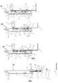
次に、図2〜図5を用いて、カートリッジ5の交換作業について、説明する。複数のカートリッジ5は、図2に示すように、装置本体1に設けられた開閉カバー(開閉部材)11を開放し、現像ローラ51を先端にしてカートリッジ装着部18(18Y、18M、18C、18K)に取り外し可能に装着される。尚、カバー11は、ヒンジ11aを中心にして回動する。カートリッジ装着部18は、装置本体1に設けられている。各カートリッジ5は、垂直方向に並べてカートリッジ装着部18に着脱可能である。一方、図2、図4(A)に示すように、装置本体1にはガイド溝(本体側ガイド部)12(12Y、12M、12C、12K)が設けられている。ガイド溝12は、使用者がカートリッジ5を装置本体1(装着部18)に装着する際に、カートリッジ5の移動軌跡を規制する。またガイド溝12は、使用者がカートリッジ5を装置本体1(装着部18)から取り外す際に、カートリッジ5の移動軌跡を規制する。また、ガイド溝12は、装置本体1の内壁1aに設けられている。即ち、ガイド溝12は、装着部18において、装着方向Xと交差する方向の一端側と他端側に互いに向き合って設けられている。ガイド溝12は図4(B)に示すように、カートリッジ5を装着する際に、ガイド部材54と係合する形状になっている。なお、本実施例において、図3に示すように、ガイド部材54の高さ方向の幅hは、現像枠体53(カートリッジ5)の高さ方向の幅Hよりも狭く設定している。しかしながら、幅hは、現像枠体53の高さ方向の幅Hと同じ幅に設定しても良い。この場合には、現像枠体53にガイド部材としての機能を持たせることができる。
尚、移動軌跡とは、ガイド部材(カートリッジ側ガイド部)54がガイド溝(本体側ガイド部)12と係合した後に、カートリッジ5が装着部18(画像形成を行うための装着位置)に到達するまでの移動経路である。本実施例では、本体側ガイド部が溝12である。また、カートリッジ側ガイド部が、カートリッジ5を装置本体1に装着する装着方向に沿って長細形状、且つ、枠体53から外方に突出したガイド部材54である。従って、ガイド部材54がガイド溝12に上下を規制された状態で、即ち、その移動軌跡を規制された状態で、カートリッジ5は、所定の装着部18にガイドされる。しかしながら、本実施例はこれに限定されない。例えば、カートリッジ側ガイド部が溝であって、また、本体側ガイド部が突出部であっても良い。この場合であっても、カートリッジ5は、上下を規制された状態で、即ち、その移動軌跡を規制された状態で、所定の装着部18にガイドされる。また、例えば、カートリッジ側ガイド部が突出部であって、また、本体側ガイド部が突出部であっても良い。この場合には、カートリッジ側ガイド部としての突出部が、本体側ガイド部としての突出部に支持された状態で、カートリッジ5は、所定の装着部18にガイドされる。このような場合には、カートリッジ5は、下方への移動を規制された状態で、即ち、その移動軌跡を規制された状態で、所定の装着部18にガイドされる。尚、後述する実施例においても同様である。尚、枠体53(53Y、53M、53C、53K)は、カートリッジ53の外壁である。
[Developer cartridge replacement]
Next, the replacement work of the cartridge 5 will be described with reference to FIGS. As shown in FIG. 2, the plurality of cartridges 5 open the opening / closing cover (opening / closing member) 11 provided in the apparatus main body 1, with the developing roller 51 at the tip, and the cartridge mounting portion 18 (18 Y, 18 M, 18 C, 18 K). ) Is detachably mounted. The cover 11 rotates around the hinge 11a. The cartridge mounting portion 18 is provided in the apparatus main body 1. The cartridges 5 can be attached to and detached from the cartridge mounting portion 18 in the vertical direction. On the other hand, as shown in FIGS. 2 and 4A, the apparatus main body 1 is provided with guide grooves (main body side guide portions) 12 (12Y, 12M, 12C, 12K). The guide groove 12 regulates the movement locus of the cartridge 5 when the user mounts the cartridge 5 on the apparatus main body 1 (mounting portion 18). Further, the guide groove 12 regulates the movement locus of the cartridge 5 when the user removes the cartridge 5 from the apparatus main body 1 (mounting portion 18). The guide groove 12 is provided on the inner wall 1 a of the apparatus main body 1. That is, the guide groove 12 is provided in the mounting portion 18 so as to face each other on one end side and the other end side in the direction intersecting the mounting direction X. As shown in FIG. 4B, the guide groove 12 is shaped to engage with the guide member 54 when the cartridge 5 is mounted. In this embodiment, as shown in FIG. 3, the width h in the height direction of the guide member 54 is set to be narrower than the width H in the height direction of the developing device frame 53 (cartridge 5). However, the width h may be set to the same width as the width H of the developing frame 53 in the height direction. In this case, the developing frame 53 can have a function as a guide member.
The movement trajectory means that after the guide member (cartridge side guide portion) 54 is engaged with the guide groove (main body side guide portion) 12, the cartridge 5 reaches the mounting portion 18 (mounting position for image formation). It is a movement route until. In the present embodiment, the main body side guide portion is the groove 12. The cartridge-side guide portion is a guide member 54 that is elongated along the mounting direction in which the cartridge 5 is mounted on the apparatus main body 1 and protrudes outward from the frame 53. Accordingly, the cartridge 5 is guided to the predetermined mounting portion 18 in a state where the guide member 54 is restricted in the vertical direction by the guide groove 12, that is, in a state where the movement locus thereof is restricted. However, the present embodiment is not limited to this. For example, the cartridge side guide portion may be a groove, and the main body side guide portion may be a protruding portion. Even in this case, the cartridge 5 is guided to the predetermined mounting portion 18 in a state where the top and bottom thereof are restricted, that is, in a state where the movement locus thereof is restricted. Further, for example, the cartridge side guide portion may be a protruding portion, and the main body side guide portion may be a protruding portion. In this case, the cartridge 5 is guided to the predetermined mounting portion 18 in a state where the protruding portion as the cartridge side guide portion is supported by the protruding portion as the main body side guide portion. In such a case, the cartridge 5 is guided to the predetermined mounting portion 18 in a state where the downward movement is restricted, that is, in a state where the movement locus is restricted. The same applies to the embodiments described later. The frame 53 (53Y, 53M, 53C, 53K) is an outer wall of the cartridge 53.

以下、図4(A)、図5を用いて、カートリッジ5Mの装着方法を例に挙げて説明する。尚、他のカートリッジ5についても同様であるため、説明は割愛する。
図4(A)に示すように、カートリッジ5Mを装着する際には、装置本体1には、これに隣接するカートリッジ5Y、5Cは、既に装置本体1(装着部18)に装着されている。そのため、カートリッジ5Mは、カートリッジ5Y(枠体53Y)やカートリッジ5C(枠体53C)及び装置本体1の外壁1cに設けられた開口1bに向かって装着される(図4)。まず、カートリッジ5Mを図4(A)に示すように、現像ローラ51Mを先端にして、ガイド部材54Mとガイド溝12Mの位置合わせを行い、開口1bに向かってカートリッジ5Mを移動させる。本実施例によれば、位置合わせが出来ていない場合には、ガイド部材54Mの先端が装置本体1の外壁1cや、すでに装着されている隣接したカートリッジ5Y、5C(枠体53Y、53C)に接触する。そのため、これ以上カートリッジ5Mを装着方向Xへ移動することは出来ない。尚、ガイド部材54Mは現像ローラ51Mの先端51aよりも装着方向X前方(装着方向下流側)に突出している。そのため、装置本体1の外壁1cやカートリッジ5Y、5Cに現像ローラ51Mを接触させることはない。これによって、本実施例によれば、現像ローラ51Mが傷付くことを未然に防止することができる。即ち本実施例によれば、前述した位置合わせが出来ていない状態で、カートリッジ5Mを装置本体1に装着しようとした場合に、現像ローラ51Mが本体1側の部材に接触するのを防止することができる突出長さでもってガイド部材54Mが設けられている。及び、ガイド部材54Mは、現像ローラ51Mの一端側と他端側でもって、現像ローラ51Mが本体1側の部材に接触するのを防止することができる位置に設けられている。ここで、装置本体1側の部材とは、例えば、装置本体1に設けられた内壁1a,外壁1c及び/又はカートリッジ装着部18に既に装着されている隣接するカートリッジ及び/又はカートリッジ装着部18等である。他のカートリッジ5も同様な構成である。
Hereinafter, the mounting method of the cartridge 5M will be described as an example with reference to FIGS. Since the same applies to the other cartridges 5, description thereof is omitted.
As shown in FIG. 4A, when the cartridge 5M is mounted, the cartridge 5Y and 5C adjacent to the apparatus body 1 are already mounted on the apparatus body 1 (mounting portion 18). Therefore, the cartridge 5M is mounted toward the cartridge 5Y (frame 53Y), the cartridge 5C (frame 53C), and the opening 1b provided in the outer wall 1c of the apparatus body 1 (FIG. 4). First, as shown in FIG. 4A, the developing roller 51M is used as the tip of the cartridge 5M, the guide member 54M and the guide groove 12M are aligned, and the cartridge 5M is moved toward the opening 1b. According to the present embodiment, when the alignment is not completed, the tip of the guide member 54M is attached to the outer wall 1c of the apparatus main body 1 or the adjacent cartridges 5Y and 5C (frame bodies 53Y and 53C) that are already mounted. Contact. Therefore, the cartridge 5M cannot be moved further in the mounting direction X. The guide member 54M projects forward in the mounting direction X (downstream in the mounting direction) from the tip 51a of the developing roller 51M. Therefore, the developing roller 51M is not brought into contact with the outer wall 1c of the apparatus main body 1 and the cartridges 5Y and 5C. Thereby, according to the present embodiment, it is possible to prevent the developing roller 51M from being damaged. That is, according to the present embodiment, when the cartridge 5M is to be mounted on the apparatus main body 1 in a state where the above-described alignment is not performed, the developing roller 51M is prevented from coming into contact with a member on the main body 1 side. The guide member 54M is provided with a projecting length that allows the projection. The guide member 54M is provided at a position where one end side and the other end side of the developing roller 51M can prevent the developing roller 51M from contacting a member on the main body 1 side. Here, the member on the apparatus main body 1 side is, for example, an inner wall 1a, an outer wall 1c provided in the apparatus main body 1 and / or an adjacent cartridge and / or a cartridge mounting portion 18 already mounted on the cartridge mounting portion 18 or the like. It is. The other cartridges 5 have the same configuration.

図5に示すように、カートリッジ5Mを開口1bに挿入していくとき、まずガイド部材54Mとガイド溝12Mが係合される。このままカートリッジ5Mを更に装置本体1の奥に向かって挿入する。そして、現像ローラ51Mが開口1bに到達する時には、カートリッジ5Mの装着時の移動軌跡は、ガイド部材54Mとガイド溝12Mとの係合によって規制される。更に、カートリッジ5Mを装置本体1の奥に向かって移動する。これによって、現像ローラ51Mが、隣接するカートリッジ5Y(枠体53Y)やカートリッジ5C(枠体53C)と接触することなく、カートリッジ5Mを装着部18Mに装着することができる。尚、カートリッジ5Mを装置本体1から取り外す際には、この操作の反対の操作を行えばよい。   As shown in FIG. 5, when the cartridge 5M is inserted into the opening 1b, the guide member 54M and the guide groove 12M are first engaged. In this state, the cartridge 5M is further inserted toward the back of the apparatus main body 1. When the developing roller 51M reaches the opening 1b, the movement trajectory when the cartridge 5M is mounted is restricted by the engagement between the guide member 54M and the guide groove 12M. Further, the cartridge 5M is moved toward the back of the apparatus main body 1. Thus, the developing roller 51M can be mounted on the mounting portion 18M without contacting the adjacent cartridge 5Y (frame body 53Y) or cartridge 5C (frame body 53C). When removing the cartridge 5M from the apparatus main body 1, an operation opposite to this operation may be performed.

現像ローラ51Mが開口1bを通過する間、ガイド部材54Mとガイド溝12Mは係合している。従って、カートリッジ5Mを装置本体1から取り外す際に、内壁1aやカートリッジ5Y、5C(枠体53Y、53C)に現像ローラ51Mを接触させてしまうことはない。よって、現像ローラ51Mの損傷を防止することができる。また、現像ローラ51Mの表面にトナーが付着している場合であっても、カートリッジ5Y、5C(枠体53Y、53C)をトナーで汚してしまうことを防止できる。   While the developing roller 51M passes through the opening 1b, the guide member 54M and the guide groove 12M are engaged. Therefore, when the cartridge 5M is removed from the apparatus main body 1, the developing roller 51M is not brought into contact with the inner wall 1a or the cartridges 5Y and 5C (frame bodies 53Y and 53C). Therefore, damage to the developing roller 51M can be prevented. Further, even when the toner adheres to the surface of the developing roller 51M, it is possible to prevent the cartridges 5Y and 5C (frame bodies 53Y and 53C) from being stained with toner.

以上説明したように、本実施例によれば、画像形成装置200の小型化を実現するために、開口1bを縮小しても、現像ローラ51にダメージを与えたり、周囲をトナーで汚したりすることはない。従って、カートリッジ5の交換を円滑に行うことができる。   As described above, according to the present embodiment, in order to reduce the size of the image forming apparatus 200, even if the opening 1b is reduced, the developing roller 51 is damaged or the surroundings are stained with toner. There is nothing. Therefore, the cartridge 5 can be exchanged smoothly.

本実施例において、ガイド部材54は、現像ローラ51よりも装着方向X前方(装着方向X下流側)に突出する突出部54aを有する。しかしながら、図6(A)に示すように、突出部55をカートリッジ5(枠体53)に設けても良い。突出部55は現像ローラ51よりも装着方向X下流側(装着方向X前方)に突出するように配置されている。カートリッジ5を装置本体1(装着部18)に装着する時、ガイド溝(本体側ガイド部)12とガイド部材(第一の現像カートリッジ側ガイド部)54の位置があっていない状態で、カートリッジ5を装置本体1に挿入しようとしても突出部55が、装置本体の内壁1a、外壁1cや隣接するカートリッジに接触する。従って本実施例によれば、現像ローラ51を傷付ける、及び、現像ローラ51からトナーが落下することを未然に防止できる。更に、突出部55に、ガイド溝12と係合し、カートリッジ5の移動軌跡を規制するガイド機能を持たせても良い。   In this embodiment, the guide member 54 has a protruding portion 54 a that protrudes forward in the mounting direction X (downstream in the mounting direction X) with respect to the developing roller 51. However, as shown in FIG. 6A, the protruding portion 55 may be provided on the cartridge 5 (frame body 53). The projecting portion 55 is disposed so as to project downstream from the developing roller 51 in the mounting direction X (forward in the mounting direction X). When the cartridge 5 is mounted on the apparatus main body 1 (mounting portion 18), the cartridge 5 is in a state where the guide groove (main body side guide portion) 12 and the guide member (first developing cartridge side guide portion) 54 are not positioned. Even if it is intended to be inserted into the apparatus main body 1, the protruding portion 55 comes into contact with the inner wall 1a, the outer wall 1c and the adjacent cartridge of the apparatus main body. Therefore, according to this embodiment, it is possible to prevent the developing roller 51 from being damaged and the toner from dropping from the developing roller 51 in advance. Further, the protrusion 55 may be provided with a guide function that engages with the guide groove 12 and regulates the movement trajectory of the cartridge 5.

また、図6(B)に示すように、ガイド部材54に、現像ローラ51の先端51aよりも更に装着方向Xの下流側(前方)に突出した突出部としての、第二のガイド部54aを設けてもよい。例えば、枠体53において、現像ローラ51の長手方向の一端と他端とに突出部(第二の現像カートリッジ側ガイド部)54aを設けても良い。図3に示す実施例においては、突出部54aは、ガイド部材54と一体であるが、図6(B)に示すように、突出部54aをガイド部材54とは別体に設けても良い。これらの実施例の場合に、突出部54aは、ガイド溝(本体側ガイド部)12と係合して、カートリッジ5を案内するための第二のガイド部としての機能を有する。
尚、突出部54aが先端51aから装着方向Xの下流側(前方)に突出する突出長及び突出部54aの幅hは、例えば現像ローラ51の曲率を考慮して適宜定めれば良い。
Further, as shown in FIG. 6B, the guide member 54 is provided with a second guide portion 54a as a protruding portion protruding further downstream (frontward) in the mounting direction X than the tip 51a of the developing roller 51. It may be provided. For example, the frame 53 may be provided with protruding portions (second developing cartridge side guide portions) 54 a at one end and the other end in the longitudinal direction of the developing roller 51. In the embodiment shown in FIG. 3, the protrusion 54 a is integral with the guide member 54, but the protrusion 54 a may be provided separately from the guide member 54 as shown in FIG. In these embodiments, the protrusion 54 a engages with the guide groove (main body side guide portion) 12 and functions as a second guide portion for guiding the cartridge 5.
It should be noted that the protrusion length at which the protrusion 54a protrudes downstream (forward) in the mounting direction X from the tip 51a and the width h of the protrusion 54a may be appropriately determined in consideration of the curvature of the developing roller 51, for example.

次に、実施例2について、説明する。本実施例はカートリッジ5のガイド部材(現像カートリッジ側ガイド部)56を移動可能にしたものである。装置本体などの構成については実施例1と同様なため、説明は割愛する。   Next, Example 2 will be described. In this embodiment, the guide member (developing cartridge side guide portion) 56 of the cartridge 5 is movable. Since the configuration of the apparatus main body is the same as that of the first embodiment, the description thereof is omitted.

[現像枠体]
枠体53には、図8に示すように、現像ローラ51に印加するための現像バイアスを装置本体1から受けるための電気接点である現像バイアス電気接点(以下、現像電極という。)532が設けられている。尚、枠体53は、現像ローラ51とトナー収容部52とを一体に有する(支持する)。ガイド部材(現像カートリッジ側ガイド部)56は、カートリッジ5を装置本体1に着脱する際に、ガイド溝(本体側ガイド部)12と係合して、カートリッジ5の移動軌跡を規制する。また、枠体53には、ガイド部材56を退避位置P2に係止する係止部材の一部であるロック穴531が設けられている。ロック穴531は、装着方向Xにおいて、ガイド部材56の上流側に設けられている。
[Development frame]
As shown in FIG. 8, the frame 53 is provided with a developing bias electrical contact (hereinafter referred to as a developing electrode) 532 that is an electrical contact for receiving a developing bias to be applied to the developing roller 51 from the apparatus main body 1. It has been. Note that the frame 53 integrally includes (supports) the developing roller 51 and the toner storage portion 52. The guide member (developing cartridge side guide portion) 56 engages with the guide groove (main body side guide portion) 12 when the cartridge 5 is attached to and detached from the apparatus main body 1 to restrict the movement locus of the cartridge 5. Further, the frame 53 is provided with a lock hole 531 which is a part of a locking member for locking the guide member 56 at the retracted position P2. The lock hole 531 is provided on the upstream side of the guide member 56 in the mounting direction X.

[ガイド部材]
ガイド部材56は図7に示すように、装着方向X方向に沿って移動可能となっている。ここで、装着方向X方向とは、カートリッジ5の短手方向であり、及び、現像ローラ51の長手方向と交差(直交)する方向である。図7(A)はガイド部材56が現像ローラ51の先端51aよりも装着方向X方向下流側に突出した状態(以下、突出位置P1と称す。)であり、図7(B)はガイド部材56の先端が現像ローラ51の先端51aよりも装着方向X方向上流側に退避した状態(以下、退避位置P2と称す。)を示している。図8に示すように、ガイド部材56には、ガイドカム561、カムバネ(弾性部材)562、ガイド部材56の付勢部材であるガイドバネ(弾性部材)563が設けられている。また、図8に示すように、ガイド部材56が突出位置P1にあるとき、現像電極532はガイド部材56のカバー部56aに覆われている。これにより、電極532は保護された状態となっている。カバー部56aは、突出部として機能する。カートリッジ5が装置本体1の外部にあるときは、ガイド部材56が突出位置P1にある。ガイド部材56が突出位置P1にあるとき、カバー部としての突出部56aは、現像ローラ51の先端51aよりも装着方向X下流側に突出している。ガイドカム561は回転中心561aを中心にして揺動可能に支持され、バネ562の弾性力によって反時計方向に付勢される。バネ563の一端部は、現像枠体53の一端バネ取付部53aに連結され、バネ563の他端部は、ガイド部材56の他端バネ取付部56bに連結されている。ガイド部材56は、バネ563の弾性力によって退避位置P2から突出位置P1に向かって、弾性的に付勢されている。カム561には、第一当接部561b、第二当接部(係止部)561c、第三当接部(係止解除部)561dが設けられている。図8に示すように、ガイド部材56が突出位置P1にあるとき、第二当接部561cは現像枠体53の壁面53bに当接している。そのため、バネ562の弾性力(付勢力)が作用しても、カム561は、これ以上反時計方向に揺動することは出来ない。しかし、ガイド部材56が、図7(B)に示すように、退避位置P2に移動したとき、第二当接部561cは、ロック穴531に引き込まれる。そして、バネ562の弾性力によって、カム561は、反時計方向に揺動可能となる。第二当接部561cがロック穴531に係合した状態において、ガイド部材56は、退避位置P2に係止された状態になる。この状態から、カム561を時計方向に揺動させて、第二当接部561cとロック穴531との係合を解除すると、ガイド部材56の係止が解除される。そして、バネ563の弾性力により、ガイド部材56は退避位置P2から突出位置P1に移動する。つまり、ガイド部材56は突出位置P1から退避位置P2に移動可能に設けられており、バネ563の弾性力によって、突出位置P1に付勢されている。更に、カム561、バネ562、ロック穴531により、ガイド部材56は退避位置P2に係止すること、また、係止を解除することが可能となる。更に、電極532は、ガイド部材56が図7(A)に示すように突出位置P1に位置しているとき、ガイド部材56のカバー部56aによって保護されている。ガイド部材56が図7(B)に示すように退避位置P2にあるとき、現像電極532はカバー部56aから露出するように構成される。
[Guide material]
As shown in FIG. 7, the guide member 56 is movable along the mounting direction X direction. Here, the mounting direction X direction is a short direction of the cartridge 5 and a direction intersecting (orthogonal) with the longitudinal direction of the developing roller 51. 7A shows a state in which the guide member 56 protrudes downstream in the mounting direction X direction from the tip 51a of the developing roller 51 (hereinafter referred to as a protruding position P1), and FIG. The front end of the developing roller 51 is retracted to the upstream side in the mounting direction X from the front end 51a of the developing roller 51 (hereinafter referred to as a retracted position P2). As shown in FIG. 8, the guide member 56 is provided with a guide cam 561, a cam spring (elastic member) 562, and a guide spring (elastic member) 563 that is a biasing member of the guide member 56. As shown in FIG. 8, when the guide member 56 is in the protruding position P <b> 1, the developing electrode 532 is covered with the cover portion 56 a of the guide member 56. Thereby, the electrode 532 is in a protected state. The cover part 56a functions as a protruding part. When the cartridge 5 is outside the apparatus main body 1, the guide member 56 is in the protruding position P1. When the guide member 56 is in the protruding position P1, the protruding portion 56a as the cover portion protrudes downstream in the mounting direction X from the tip 51a of the developing roller 51. The guide cam 561 is supported to be swingable about the rotation center 561a, and is biased counterclockwise by the elastic force of the spring 562. One end of the spring 563 is coupled to the one end spring mounting portion 53 a of the developing device frame 53, and the other end of the spring 563 is coupled to the other end spring mounting portion 56 b of the guide member 56. The guide member 56 is elastically biased by the elastic force of the spring 563 from the retracted position P2 toward the protruding position P1. The cam 561 is provided with a first contact portion 561b, a second contact portion (locking portion) 561c, and a third contact portion (lock release portion) 561d. As shown in FIG. 8, when the guide member 56 is at the protruding position P <b> 1, the second contact portion 561 c is in contact with the wall surface 53 b of the developing device frame 53. Therefore, even if the elastic force (biasing force) of the spring 562 is applied, the cam 561 can no longer swing counterclockwise. However, when the guide member 56 moves to the retracted position P2 as shown in FIG. 7B, the second contact portion 561c is pulled into the lock hole 531. The cam 561 can swing counterclockwise by the elastic force of the spring 562. In a state where the second contact portion 561c is engaged with the lock hole 531, the guide member 56 is locked at the retracted position P2. When the cam 561 is swung clockwise from this state and the engagement between the second contact portion 561c and the lock hole 531 is released, the locking of the guide member 56 is released. Then, due to the elastic force of the spring 563, the guide member 56 moves from the retracted position P2 to the protruding position P1. That is, the guide member 56 is movably provided from the protruding position P1 to the retracted position P2, and is biased to the protruding position P1 by the elastic force of the spring 563. Further, the cam 561, the spring 562, and the lock hole 531 make it possible to lock the guide member 56 at the retracted position P2 and to release the lock. Furthermore, the electrode 532 is protected by the cover portion 56a of the guide member 56 when the guide member 56 is located at the protruding position P1 as shown in FIG. When the guide member 56 is at the retracted position P2 as shown in FIG. 7B, the developing electrode 532 is configured to be exposed from the cover portion 56a.

[ガイド溝]
更に、図9に示すようにガイド溝12には、ガイドカム561と係合する係合部である突部121が設けられている。更に、ガイド溝12には、現像ローラ51に所定のバイアスを印加する装置本体側の電気接点(本体側電気接点)122が設けられている。
[Guide groove]
Further, as shown in FIG. 9, the guide groove 12 is provided with a protrusion 121 that is an engaging portion that engages with the guide cam 561. Further, the guide groove 12 is provided with an electric contact (main electric contact) 122 on the apparatus main body side that applies a predetermined bias to the developing roller 51.

[装着時のガイド部材の動作]
次に図10を用いてカートリッジ5を装置本体1(装着部18)に装着する時のガイド部材56、ガイドカム561の動作について説明する。なお図10(A)は、カートリッジ5を装着部18(装置本体1)装着し始めた状態を示し、以下図10(B)、図10(C)と装着動作が進行し、図10(D)は装着動作が完了した状態である。
[Operation of guide member during mounting]
Next, operations of the guide member 56 and the guide cam 561 when the cartridge 5 is mounted on the apparatus main body 1 (mounting portion 18) will be described with reference to FIG. FIG. 10A shows a state in which the cartridge 5 starts to be mounted, and the mounting operation proceeds as shown in FIGS. 10B and 10C, and FIG. ) Is a state in which the mounting operation is completed.

まず、図10(A)に示すように、カートリッジ5を装置本体1に装着する時、ガイド部材56と装置本体1のガイド溝12との位置合わせをし、装置本体1に挿入する。このとき電極532はガイド部材56のカバー部56aに覆われているため、保護されていることとなる。更にカートリッジ5の装着部18に挿入を進めていき、図10(B)の状態になると、カム561の第一当接部561b(被当接部)とガイド溝12に設けられた突部121の当接部121bが当接する。このときカム561は揺動可能に支持されているため、反時計方向にモーメントが発生する。しかし、カム561の第二当接部561cと現像枠体53の壁面53bとが当接する。そのため、カム561は、回転出来ない。従って、このままカートリッジ5を装着部18に挿入していくと、ガイド部材56は、この状態で静止したまま、カートリッジ5のその他の部分が侵入していく。図10(C)の状態に至ると、第二当接部561cは、現像枠体53に設けられたロック穴531に引き込まれる。そして、カム561は反時計方向に回転し、図10(C)に示す二点鎖線の状態から実線の状態になる。このとき第一当接部561bはガイド溝12の突部121の当接部121bから開放される。しかしながら、ガイド部材56はカム561によってこの位置に係止された状態となる。このとき、ガイド部材56は退避位置に移動を完了し、電極532はガイド部材56のカバー部56aから露出した状態となっている。このまま、カートリッジ5を装着部18に装着していけば、図10(D)に示すように、電極(カートリッジ側電気接点)532と電気接点(本体側電気接点)122とが当接する。そして、図1に示すように、カバー11を閉じることで、カートリッジ5の装着動作が完了する。このとき、カートリッジ5は加圧バネ(弾性部材)111の弾性力によってベルト31の方向に加圧される。しかし、本実施例にて説明したように、ガイド部材56は退避位置に係止されているため、バネ563の弾性力によるガイド部材56を突出位置方向に付勢する付勢力は、現像ローラ51に掛からない。よって、バネ111の弾性力により、現像ローラ51をベルト31に、適切な圧力で押圧することができる。   First, as shown in FIG. 10A, when the cartridge 5 is mounted on the apparatus main body 1, the guide member 56 and the guide groove 12 of the apparatus main body 1 are aligned and inserted into the apparatus main body 1. At this time, since the electrode 532 is covered with the cover portion 56a of the guide member 56, it is protected. Further, the insertion is advanced to the mounting portion 18 of the cartridge 5, and when the state shown in FIG. 10B is reached, the first contact portion 561b (contacted portion) of the cam 561 and the protrusion 121 provided in the guide groove 12 are provided. The abutting portion 121b abuts. At this time, since the cam 561 is supported so as to be able to swing, a moment is generated in the counterclockwise direction. However, the second contact portion 561c of the cam 561 contacts the wall surface 53b of the developing device frame 53. Therefore, the cam 561 cannot rotate. Accordingly, when the cartridge 5 is inserted into the mounting portion 18 as it is, the guide member 56 remains stationary in this state, and other portions of the cartridge 5 enter. When the state shown in FIG. 10C is reached, the second contact portion 561 c is drawn into the lock hole 531 provided in the developing device frame 53. Then, the cam 561 rotates counterclockwise and changes from a two-dot chain line state shown in FIG. 10C to a solid line state. At this time, the first contact portion 561b is released from the contact portion 121b of the protrusion 121 of the guide groove 12. However, the guide member 56 is locked at this position by the cam 561. At this time, the guide member 56 has finished moving to the retracted position, and the electrode 532 is exposed from the cover portion 56a of the guide member 56. If the cartridge 5 is mounted in the mounting portion 18 as it is, the electrode (cartridge side electrical contact) 532 and the electrical contact (main body side electrical contact) 122 come into contact with each other as shown in FIG. Then, as shown in FIG. 1, the mounting operation of the cartridge 5 is completed by closing the cover 11. At this time, the cartridge 5 is pressed in the direction of the belt 31 by the elastic force of the pressure spring (elastic member) 111. However, as described in the present embodiment, since the guide member 56 is locked at the retracted position, the urging force for urging the guide member 56 in the protruding position direction by the elastic force of the spring 563 is the developing roller 51. It does not hang. Therefore, the developing roller 51 can be pressed against the belt 31 with an appropriate pressure by the elastic force of the spring 111.

[取り外し時のガイド部の動作]
次にカートリッジ5を本体1(装着部18)から取り出す時のガイド部材56、カム561の動作について図11を用いて説明する。図11は、図11(A)、(B)、(C)、(D)に進むに従って、カートリッジ5が本体1から取り出される状態を示している。まず、図2に示すように、カバー11を開放しカートリッジ5を本体1から引き抜いていく。このとき、図11(A)に示すように、ガイド部材56は退避位置に係止された状態で引き抜かれる。そして、図11(A)に示すように、カム561の第三当接部(係止解除部)561dは突部121の斜面(係合部)121aと当接する。更にカートリッジ5を本体1(装着部18)から引き抜いていくと、図11(B)に示すように、第三当接部(係止解除部)561dは斜面(係合部)121aを乗り上げる。カム561は時計方向に回転し、第二当接部561cはロック穴531から抜け出る。つまり、ガイド部材56は、この瞬間、退避位置に係止された状態から開放された状態となる。即ち、第三当接部(係止解除部)561dは、カートリッジ5を装着部18から取り出す際に、ガイド溝(本体側ガイド部)12に設けられた斜面(係合部)121aと係合して、第二当接部(係止部)561cの係止を解除する。従って、ガイド部材56は、バネ563の弾性力によって、突出位置に向かって移動する。そして、図11(C)に示すように、カム561の第一当接部561cが突部121の当接部121bと当接する位置まで移動する。更に図11(D)に示すように、カートリッジ5を引き抜いていけば、バネ563の弾性力によってガイド部材56は突出位置に移動する。ガイド部材56のカバー部56aは、電極532を覆う。カートリッジ5は、ガイド部材56とガイド溝12の係合によって、移動軌跡が規制されている。従って、隣接するカートリッジ5等に現像ローラ51を接触させることなく、カートリッジ5を本体1から取り出すことができる。
[Operation of guide section when removing]
Next, the operation of the guide member 56 and the cam 561 when the cartridge 5 is taken out from the main body 1 (mounting portion 18) will be described with reference to FIG. FIG. 11 shows a state in which the cartridge 5 is taken out from the main body 1 as proceeding to FIGS. 11 (A), (B), (C), and (D). First, as shown in FIG. 2, the cover 11 is opened and the cartridge 5 is pulled out from the main body 1. At this time, as shown in FIG. 11A, the guide member 56 is pulled out while being locked at the retracted position. Then, as shown in FIG. 11A, the third contact portion (lock release portion) 561d of the cam 561 contacts the slope (engagement portion) 121a of the protrusion 121. Further, when the cartridge 5 is pulled out from the main body 1 (mounting portion 18), as shown in FIG. The cam 561 rotates in the clockwise direction, and the second contact portion 561c comes out of the lock hole 531. That is, at this moment, the guide member 56 is released from the state locked at the retracted position. That is, the third contact portion (lock release portion) 561d engages with an inclined surface (engagement portion) 121a provided in the guide groove (main body side guide portion) 12 when the cartridge 5 is taken out from the mounting portion 18. Then, the locking of the second contact portion (locking portion) 561c is released. Therefore, the guide member 56 moves toward the protruding position by the elastic force of the spring 563. Then, as shown in FIG. 11C, the first contact portion 561c of the cam 561 moves to a position where it contacts the contact portion 121b of the protrusion 121. Further, as shown in FIG. 11D, when the cartridge 5 is pulled out, the guide member 56 moves to the protruding position by the elastic force of the spring 563. The cover part 56 a of the guide member 56 covers the electrode 532. The movement path of the cartridge 5 is regulated by the engagement between the guide member 56 and the guide groove 12. Therefore, the cartridge 5 can be removed from the main body 1 without bringing the developing roller 51 into contact with the adjacent cartridge 5 or the like.

前述した実施例1において、ガイド部材54は固定式であった。そのため、カートリッジ5を本体1に装着すると、図5に示すように、ガイド部材54の先端、すなわち突出部54aがユニット3の側面に侵入することとなる。一方、本実施例のように、本体1にカートリッジ5を装着し終わったとき、ガイド部材56が図7(B)のように退避位置P2に退避する。そこで、この部分に、例えばユニット3を駆動するための駆動部やバイアスを印加するための電極などを配置することができる、従って、装置全体の更なる小型化を図ることができる。
即ち本実施例によれば、前述した位置合わせが出来ていない状態で、カートリッジ5を装置本体1に装着しようとした場合に、現像ローラ51が本体1側の部材に接触するのを防止することができる突出長さでもってガイド部材56が設けられている。及び、ガイド部材56は、現像ローラ51の一端側と他端側でもって、現像ローラ51が本体1側の部材に接触するのを防止することができる位置に設けられている。ここで、装置本体1側の部材とは、例えば、装置本体1に設けられた内壁1a,外壁1c及び/又はカートリッジ装着部18に既に装着されている隣接するカートリッジ及び/又はカートリッジ装着部18等である。
In the first embodiment described above, the guide member 54 is a fixed type. Therefore, when the cartridge 5 is mounted on the main body 1, as shown in FIG. 5, the tip of the guide member 54, that is, the protruding portion 54 a enters the side surface of the unit 3. On the other hand, when the cartridge 5 is completely attached to the main body 1 as in this embodiment, the guide member 56 is retracted to the retracted position P2 as shown in FIG. Therefore, for example, a driving unit for driving the unit 3 and an electrode for applying a bias can be arranged in this portion. Therefore, further downsizing of the entire apparatus can be achieved.
That is, according to the present embodiment, when the cartridge 5 is to be mounted on the apparatus main body 1 in a state where the above-described alignment is not possible, the developing roller 51 is prevented from contacting a member on the main body 1 side. The guide member 56 is provided with a protruding length that can be The guide member 56 is provided at a position where one end side and the other end side of the developing roller 51 can prevent the developing roller 51 from contacting a member on the main body 1 side. Here, the member on the apparatus main body 1 refers to, for example, the inner wall 1a, the outer wall 1c provided in the apparatus main body 1 and / or the adjacent cartridge and / or the cartridge mounting section 18 already mounted on the cartridge mounting section 18. It is.

本実施例は1パス方式のカラー電子写真画像形成装置に関する。1パス方式の画像形成装置はイエロー色、マゼンタ色、シアン色、ブラック色に対応する画像形成部をそれぞれ有しており、これらの色を順次重ね合わせることでカラー画像を形成する。実施例1、2で説明した4パス方式の画像形成装置に比べ、1パス方式の画像形成装置は、カラー画像の高速出力が可能となるという利点がある。
次に実施例3について説明する。なお、本実施例において、先に説明した実施例1、2と同一符号のものは、同一機能のものであるため説明は割愛する。
This embodiment relates to a one-pass color electrophotographic image forming apparatus. The one-pass image forming apparatus has image forming units corresponding to yellow, magenta, cyan, and black, respectively, and forms a color image by sequentially superimposing these colors. Compared to the 4-pass image forming apparatus described in the first and second embodiments, the 1-pass image forming apparatus has an advantage that a color image can be output at high speed.
Next, Example 3 will be described. In the present embodiment, the same reference numerals as those in the first and second embodiments described above have the same functions, and thus the description thereof is omitted.

[カラー電子写真画像形成装置]
図12は本実施例のカラー電子写真画像形成装置本体(以下、装置本体という。)100の断面図である。装置本体100の中央部には、4つの電子写真感光体ドラム(以下、ドラムという。)310(310Y、310M、310C、310K)が並列に配置されている。それぞれのドラム310に対してイエロー色、マゼンタ色、シアン色、ブラック色のトナーを収容したカートリッジ50(50Y、50M、50C、50K)が取り外し可能に装着される。尚、装置本体100とは、画像形成装置300からカートリッジ30、50を除いた構成である。ドラム310の上方にはスキャナーユニット20が配置され、それぞれのドラム310に対して、静電潜像を形成するためのレーザー光LY、LM、LC、LKが照射される。ドラム310の下方には転写部70が配置され、更にその下方には、記録媒体である紙82を収容するカセット81が配置される。
以下、各部について、詳細に説明するが、本実施例において、給紙部8、定着部9、排紙部10に関しては実施例1と同様であるため、説明は割愛する。
[Color electrophotographic image forming apparatus]
FIG. 12 is a cross-sectional view of a color electrophotographic image forming apparatus main body (hereinafter referred to as the apparatus main body) 100 of this embodiment. Four electrophotographic photosensitive drums (hereinafter referred to as drums) 310 (310Y, 310M, 310C, 310K) are arranged in parallel at the center of the apparatus main body 100. A cartridge 50 (50Y, 50M, 50C, 50K) containing yellow, magenta, cyan, and black toners is detachably mounted on each drum 310. The apparatus main body 100 is configured by removing the cartridges 30 and 50 from the image forming apparatus 300. The scanner unit 20 is disposed above the drums 310, and each drum 310 is irradiated with laser beams LY, LM, LC, and LK for forming an electrostatic latent image. A transfer unit 70 is disposed below the drum 310, and a cassette 81 that houses a paper 82 that is a recording medium is further disposed below the transfer unit 70.
Hereinafter, although each part will be described in detail, in the present embodiment, the paper feed unit 8, the fixing unit 9, and the paper discharge unit 10 are the same as those in the first embodiment, and thus description thereof is omitted.

[プロセスカートリッジ]
プロセスカートリッジ30(30Y、30M、30C、30K)は電子写真感光体ドラム310、ドラム310に作用するプロセス手段である帯電部材40、及び、クリーニング部材610をプロセス枠体301(301Y、301M、301C、301K)にて一体化したものである。更に、本実施例のカートリッジ30によれば、クリーニング部材610によってドラム310から除去されたトナーを収容する除去トナー収容部620を有する。ドラム310は円筒状のシリンダ表面に有機光導電体からなる感光層を有しており、プロセス枠体301に回転可能に支持され、駆動時には、時計方向に回転駆動される。
[Process cartridge]
The process cartridge 30 (30Y, 30M, 30C, 30K) includes an electrophotographic photosensitive drum 310, a charging member 40 that is a process unit that acts on the drum 310, and a cleaning member 610 that includes a process frame 301 (301Y, 301M, 301C, 301K). Further, the cartridge 30 according to the present embodiment includes the removed toner storage portion 620 that stores the toner removed from the drum 310 by the cleaning member 610. The drum 310 has a photosensitive layer made of an organic photoconductor on the surface of a cylindrical cylinder, is rotatably supported by the process frame 301, and is driven to rotate clockwise when driven.

[現像カートリッジ]
現像カートリッジ50(50Y、50M、50C、50K)はそれぞれイエロー色、マゼンタ色、シアン色、ブラック色のトナーを収容するトナー収容部520、現像手段である現像ローラ51、及び現像ローラ51を回転自在に支持し、トナー収容部520を一体化する現像枠体530を有する。カートリッジ50Yは、イエロー色のトナーをトナー収容部520に収容している。カートリッジ50Mは、マゼンタ色のトナーをトナー収容部520に収容している。カートリッジ50Cは、シアン色のトナーをトナー収容部520に収容している。カートリッジ50Kは、ブラック色のトナーをトナー収容部520に収容している。
[Developer cartridge]
The developing cartridge 50 (50Y, 50M, 50C, 50K) can freely rotate a toner container 520 that stores yellow, magenta, cyan, and black toner, a developing roller 51 that is a developing unit, and a developing roller 51, respectively. And a developing frame 530 that integrates the toner container 520. The cartridge 50Y accommodates yellow toner in the toner accommodating portion 520. The cartridge 50M stores magenta toner in the toner storage unit 520. The cartridge 50 </ b> C stores cyan toner in the toner storage unit 520. The cartridge 50K stores black toner in the toner storage portion 520.

[転写部]
転写部70は、転写ベルト(中間転写体)710、1次転写ローラ720、2次転写対向ローラ730、転写駆動ローラ740、2次転写ローラ750を有する。
[Transfer section]
The transfer unit 70 includes a transfer belt (intermediate transfer member) 710, a primary transfer roller 720, a secondary transfer counter roller 730, a transfer driving roller 740, and a secondary transfer roller 750.

[カートリッジ交換]
次にカートリッジ30、及び、カートリッジ50の交換について説明する。カートリッジ30が有するドラム310、帯電部材(プロセス手段)40、クリーニング部材(プロセス手段)610は画像形成動作を繰り返すたびに劣化する。また、トナー収容部520も所定量の除去トナーを回収したら、それ以上のトナーを回収することは出来ない。つまり、カートリッジ30は所定回数の画像形成動作を繰り返すと、寿命を迎えることとなる。即ち、使用者が満足できる品質の画像を形成することができなくなる。そこで、カートリッジ30は所定の寿命を迎えたら、新品と交換することで、良好な画像形成動作が可能となる。カートリッジ50についても同様に、現像ローラ51の劣化やトナー収容部520に収容されたトナーの消費などによって、寿命を迎え、寿命に到達した場合は、新品と交換する必要がある。
[Cartridge replacement]
Next, replacement of the cartridge 30 and the cartridge 50 will be described. The drum 310, the charging member (process means) 40, and the cleaning member (process means) 610 included in the cartridge 30 deteriorate each time the image forming operation is repeated. Further, if the toner container 520 collects a predetermined amount of removed toner, it cannot collect more toner. That is, the cartridge 30 reaches the end of its life when the image forming operation is repeated a predetermined number of times. In other words, it becomes impossible to form an image with a quality satisfactory for the user. Therefore, when the cartridge 30 reaches a predetermined life, it can be replaced with a new one, so that a good image forming operation can be performed. Similarly, when the cartridge 50 reaches the end of its life due to deterioration of the developing roller 51 or consumption of the toner stored in the toner storage portion 520, the cartridge 50 needs to be replaced with a new one.

[トレイ部材]
カートリッジ30及びカートリッジ50は、両カートリッジ30、50のカートリッジ装着部であるトレイ13に取り外し可能に装着される。トレイ(カートリッジ装着部)13は、プロセスカートリッジ装着部及び現像カートリッジ装着部(カートリッジ装着部)である。即ち、両カートリッジ30、50は、トレイ13に支持される。トレイ13は、カートリッジ30を取り外し可能に装着する装着部13aとカートリッジ50を取り外し可能に装着する装着部13bとをトレイ13の長手方向に沿って交互に設けている。両カートリッジ30、50を交換するには、図13に示すように、カバー110を開放し、トレイ13を装置本体100から取り出す。そして、装置本体100からトレイ13を引き出した状態でカートリッジ30、50の交換作業を行う。尚、図14は、トレイ(カートリッジ装着部)13を装置本体100から引き出した状態である。この状態で、トレイ(カートリッジ装着部)13に対するカートリッジ30、50の着脱を行う。尚、トレイ13は、装置本体100内に詰まった紙82を装置本体100から取り出す際には、装置本体100から離脱しても良い(図14)。この場合には、トレイ13が装置本体100から所定量以上引き出されるのを規制しているストッパ(不図示)を解除する。尚、前述した通り、装置本体100とは、画像形成装置300からカートリッジ30、50を除いた構成であり、トレイ13も装置本体100に含まれる。
図14は、装置本体100からトレイ13を取り出し、さらにトレイ13に装着されていたカートリッジ30、50を全て取り外した状態を示している。トレイ13の側板131の内壁には、カートリッジ30をトレイ13に対して着脱するとき、カートリッジ30の移動軌跡を規制するための本体側(トレイ側)ガイドであるガイド溝(本体側ガイド部)132と、カートリッジ50をトレイ13に対して着脱するとき、カートリッジ50の移動軌跡を規制する本体側(トレイ側)ガイドであるガイド溝(本体側ガイド部)133が設けられている。カートリッジ30は、トレイ13に対して着脱する際に、ガイド溝132にガイドされる。カートリッジ50、トレイ13に対して着脱する際に、ガイド溝133にガイドされる。
[Tray material]
The cartridge 30 and the cartridge 50 are detachably mounted on the tray 13 which is a cartridge mounting portion of both the cartridges 30 and 50. The tray (cartridge mounting portion) 13 is a process cartridge mounting portion and a developing cartridge mounting portion (cartridge mounting portion). That is, both cartridges 30 and 50 are supported by the tray 13. The tray 13 is alternately provided with a mounting portion 13 a for removably mounting the cartridge 30 and a mounting portion 13 b for removably mounting the cartridge 50 along the longitudinal direction of the tray 13. In order to replace both cartridges 30 and 50, as shown in FIG. 13, the cover 110 is opened and the tray 13 is taken out from the apparatus main body 100. Then, the cartridges 30 and 50 are replaced while the tray 13 is pulled out from the apparatus main body 100. FIG. 14 shows a state in which the tray (cartridge mounting portion) 13 is pulled out from the apparatus main body 100. In this state, the cartridges 30 and 50 are attached to and detached from the tray (cartridge mounting portion) 13. The tray 13 may be detached from the apparatus main body 100 when the paper 82 jammed in the apparatus main body 100 is taken out from the apparatus main body 100 (FIG. 14). In this case, a stopper (not shown) that restricts the tray 13 from being pulled out by a predetermined amount or more from the apparatus main body 100 is released. As described above, the apparatus main body 100 is configured by removing the cartridges 30 and 50 from the image forming apparatus 300, and the tray 13 is also included in the apparatus main body 100.
FIG. 14 shows a state in which the tray 13 is removed from the apparatus main body 100 and all the cartridges 30 and 50 mounted on the tray 13 are removed. On the inner wall of the side plate 131 of the tray 13, a guide groove (main body side guide portion) 132 that is a main body side (tray side) guide for restricting the movement trajectory of the cartridge 30 when the cartridge 30 is attached to and detached from the tray 13. When the cartridge 50 is attached to and detached from the tray 13, a guide groove (main body side guide portion) 133 that is a main body side (tray side) guide that restricts the movement trajectory of the cartridge 50 is provided. The cartridge 30 is guided in the guide groove 132 when being attached to and detached from the tray 13. When being attached to and detached from the cartridge 50 and the tray 13, the cartridge is guided by the guide groove 133.

[プロセスカートリッジ側ガイド部]
図15(A)はカートリッジ30の斜視図である。カートリッジ30はドラム310を露出した状態で矢印αで示す装着方向に装着される。装着方向αは、ドラム310の長手方向と直交する方向である。プロセス枠体301の長手方向両端には、図15(A)に示すように、カートリッジ30の着脱時において、ガイド溝132と係合して、カートリッジ30の移動軌跡を規制するプロセスカートリッジ側ガイド部であるガイド320が設けられている。更に、ガイド320(第一のプロセスカートリッジ側ガイド部)の装着方向αの先端には、ドラム310の先端310aよりも突出して突出部(第二のプロセスカートリッジ側ガイド部)320aを有している。
[Process cartridge side guide]
FIG. 15A is a perspective view of the cartridge 30. The cartridge 30 is mounted in the mounting direction indicated by the arrow α with the drum 310 exposed. The mounting direction α is a direction orthogonal to the longitudinal direction of the drum 310. At both ends in the longitudinal direction of the process frame 301, as shown in FIG. 15A, when the cartridge 30 is attached or detached, a process cartridge side guide portion that engages with the guide groove 132 and regulates the movement trajectory of the cartridge 30. A guide 320 is provided. Further, the guide 320 (first process cartridge side guide portion) has a protruding portion (second process cartridge side guide portion) 320a protruding from the tip 310a of the drum 310 at the tip end in the mounting direction α. .

[現像カートリッジ側ガイド部]
図15Bはカートリッジ50の斜視図である。カートリッジ50は現像ローラ51を露出した状態で矢印βで示す装着方向に装着される。装着方向βは、現像ローラ51の長手方向と直交行する方向である。現像枠体530の長手方向一端と他端には、図15Bに示すように、カートリッジ50をトレイ13に対して着脱時において、ガイド溝133と係合して、カートリッジ50の移動軌跡を規制する現像カートリッジ側ガイド部であるガイド540が設けられている。更にガイド540の装着方向βの先端には、現像ローラ51の先端51aよりも装着方向βの下流側に突出した突出部540aが設けられている。
[Developing cartridge side guide]
FIG. 15B is a perspective view of the cartridge 50. The cartridge 50 is mounted in the mounting direction indicated by the arrow β with the developing roller 51 exposed. The mounting direction β is a direction orthogonal to the longitudinal direction of the developing roller 51. At one end and the other end in the longitudinal direction of the developing device frame 530, as shown in FIG. 15B, when the cartridge 50 is attached to and detached from the tray 13, the guide groove 133 is engaged to restrict the movement trajectory of the cartridge 50. A guide 540 serving as a developing cartridge side guide is provided. Further, a protrusion 540 a that protrudes downstream of the tip 51 a of the developing roller 51 in the mounting direction β is provided at the tip of the guide 540 in the mounting direction β.

[カートリッジのトレイに対する装着作業]
次に図16、図17を用いて、トレイ13にカートリッジ30、50を装着する装着方法について説明する。なお、本説明において、交換するカートリッジはカートリッジ50Mと対応するカートリッジ30Mであり、交換するカートリッジはシアンの現像カートリッジ50Cとする。カートリッジ30、及び、カートリッジ50はそれぞれ独立して交換が可能である。従って、交換する必要のないカートリッジ30Y、30C、30K、及び、カートリッジ50Y、50M、50Kはトレイ部材13に、すでに装着した状態となっている。
[Installation of cartridge to tray]
Next, a mounting method for mounting the cartridges 30 and 50 on the tray 13 will be described with reference to FIGS. In this description, the cartridge to be replaced is the cartridge 30M corresponding to the cartridge 50M, and the cartridge to be replaced is the cyan developing cartridge 50C. The cartridge 30 and the cartridge 50 can be replaced independently. Accordingly, the cartridges 30Y, 30C, and 30K that do not need to be replaced and the cartridges 50Y, 50M, and 50K are already mounted on the tray member 13.

図16に示すように、トレイ13の側板131に設けられたガイド溝132Mはプロセスカートリッジ側ガイド320Mを受けるように設けられている。また、ガイド溝133Cは現像カートリッジ側ガイド540Cを受けるように設けられている。カートリッジ30Mは、図17に示すように、トレイ13の上方向からドラム310Mを下に向け、矢印α方向に装着される。まず、ガイド320Mとガイド溝132Mの位置合わせを行い、次いで、カートリッジ30Mをトレイ13に挿入していく。この位置があっていない場合には、ガイド320Mの突出部320aと側板131とが接触する。そのため、カートリッジ30Mはそれ以上奥に挿入できない。このとき、ガイド320Mの突出部320aはドラム310Mの先端310aよりも装着方向αの下流側に突出している。そのため、ドラム310Mがトレイ13と接触してドラム310Mを損傷することはない。ガイド320Mとガイド溝132Mの位置を合わせ、カートリッジ30Mをトレイ13に挿入していくとき、カートリッジ30Mの装着時の移動軌跡は、ガイド320Mとガイド溝132Mの係合によって規制される。つまり、ドラム310Mが、これと隣接する現像枠体530Y、530M及びトレイ13の側板131に設けられた開口131aを通過するときには、すでにカートリッジ30Mの装着軌跡が規制されている。そのため、ドラム310Mを損傷することなく、トレイ13に対する装着ができる。カートリッジ50Cは、プロセス枠体301Cと、プロセス枠体301Kと側板131によって構成された開口131bに向かって矢印βで示す装着方向に装着する。このとき、カートリッジの装着方法で説明したのと同様に、開口131bを現像ローラ51Cが通過するときにはガイド540Cとガイド溝133Cとの係合によって、カートリッジ50Cの移動軌跡は規制される。従って、現像ローラ51Cをトレイ13等に接触させて損傷することなく、カートリッジ50Cのトレイ13に対する装着ができる。尚、カートリッジ30M、カートリッジ50Cをそれぞれトレイ13から取り外すときは、前述した装着動作と反対の操作を行えばよい。このように、本実施例によれば、使用者が、トレイ13にカートリッジ30、50を支持した状態(装着した状態)で、トレイ13を本体100の内側に押し込むことによって、カートリッジ30、50は装置本体100の画像形成位置に装着される。また、使用者が、トレイ13にカートリッジ30、50を支持した状態で、トレイ13を本体100から外側に引き出すことによって、カートリッジ30、50は装置本体100から取り出すことができる。尚、トレイ13を本体100の内側に押し込むことによって、カートリッジ30、50は装置本体100の画像形成位置に位置させる構成については、公知の構成を適宜適用することができる。
なお、本実施例において、本体側ガイド部は、トレイ13の側板131に設けられたガイド溝132及び133である。また、カートリッジ側ガイド部は、カートリッジ30及び50をトレイ13に装着する装着方向α及びβに沿って長細形状、且つ、枠体301及び530から外方に突出したガイド部材320及び540である。従って、ガイド部材320及び540がガイド溝132及び133にトレイ13の引き出し方向の上流側及び下流側を規制された状態で、即ち、その移動軌跡を規制された状態で、カートリッジ30及び50は、所定の装着部13a及び13bへガイドされる。しかしながら、本実施例はこれに限定されない。例えば、カートリッジ側ガイド部が溝であって、また、本体側ガイド部が突出部であっても良い。この場合であっても、カートリッジ30及び50は、引き出し方向の上流側及び下流側を規制された状態で、即ち、その移動軌跡を規制された状態で、所定の装着部13a及び13bへガイドされる。また、例えば、カートリッジ側ガイド部が突出部であって、また、本体側ガイド部が突出部であっても良い。この場合には、カートリッジ側ガイド部としての突出部が、本体側ガイド部としての突出部に支持された状態で、カートリッジ30及び50は、所定の装着部13a及び13bにガイドされる。このような場合には、カートリッジ30及び50は、引き出し方向の上流側又は下流側のどちらかへの移動を規制された状態で、即ち、その移動軌跡を規制された状態で、所定の装着部13a及び13bへガイドされる。
As shown in FIG. 16, the guide groove 132M provided in the side plate 131 of the tray 13 is provided to receive the process cartridge side guide 320M. The guide groove 133C is provided so as to receive the developing cartridge side guide 540C. As shown in FIG. 17, the cartridge 30M is mounted in the direction of the arrow α with the drum 310M facing downward from above the tray 13. First, the guide 320M and the guide groove 132M are aligned, and then the cartridge 30M is inserted into the tray 13. When this position is not present, the protrusion 320a of the guide 320M and the side plate 131 are in contact with each other. Therefore, the cartridge 30M cannot be inserted any further. At this time, the protruding portion 320a of the guide 320M protrudes further downstream in the mounting direction α than the tip 310a of the drum 310M. Therefore, the drum 310M does not come into contact with the tray 13 to damage the drum 310M. When the positions of the guide 320M and the guide groove 132M are aligned and the cartridge 30M is inserted into the tray 13, the movement trajectory when the cartridge 30M is mounted is regulated by the engagement of the guide 320M and the guide groove 132M. That is, when the drum 310M passes through the developing frame bodies 530Y and 530M adjacent to the drum 310M and the opening 131a provided in the side plate 131 of the tray 13, the mounting locus of the cartridge 30M is already restricted. Therefore, it is possible to mount the tray 13 without damaging the drum 310M. The cartridge 50C is mounted in the mounting direction indicated by the arrow β toward the opening 131b formed by the process frame 301C, the process frame 301K, and the side plate 131. At this time, as described in the cartridge mounting method, when the developing roller 51C passes through the opening 131b, the movement locus of the cartridge 50C is regulated by the engagement between the guide 540C and the guide groove 133C. Therefore, the cartridge 50C can be mounted on the tray 13 without causing the developing roller 51C to come into contact with the tray 13 or the like to be damaged. When removing the cartridge 30M and the cartridge 50C from the tray 13, respectively, the operation opposite to the mounting operation described above may be performed. As described above, according to the present embodiment, when the user pushes the tray 13 into the main body 100 while the cartridges 30 and 50 are supported (mounted) on the tray 13, the cartridges 30 and 50 are Attached to the image forming position of the apparatus main body 100. Further, when the user pulls out the tray 13 from the main body 100 while the cartridges 30 and 50 are supported on the tray 13, the cartridges 30 and 50 can be taken out from the apparatus main body 100. A known configuration can be appropriately applied to the configuration in which the cartridges 30 and 50 are positioned at the image forming position of the apparatus main body 100 by pushing the tray 13 into the main body 100.
In this embodiment, the main body side guide portions are guide grooves 132 and 133 provided in the side plate 131 of the tray 13. The cartridge-side guide portions are guide members 320 and 540 that are elongated along the mounting directions α and β for mounting the cartridges 30 and 50 on the tray 13 and project outward from the frame bodies 301 and 530. . Accordingly, the cartridges 30 and 540 are in a state in which the guide members 320 and 540 are regulated by the guide grooves 132 and 133 on the upstream side and the downstream side in the pull-out direction of the tray 13, that is, in a state where the movement trajectory is regulated. Guided to predetermined mounting portions 13a and 13b. However, the present embodiment is not limited to this. For example, the cartridge side guide portion may be a groove, and the main body side guide portion may be a protruding portion. Even in this case, the cartridges 30 and 50 are guided to the predetermined mounting portions 13a and 13b in a state where the upstream side and the downstream side in the pull-out direction are restricted, that is, in a state where the movement trajectory is restricted. The Further, for example, the cartridge side guide portion may be a protruding portion, and the main body side guide portion may be a protruding portion. In this case, the cartridges 30 and 50 are guided by the predetermined mounting portions 13a and 13b in a state where the protruding portion as the cartridge side guide portion is supported by the protruding portion as the main body side guide portion. In such a case, the cartridges 30 and 50 are in a state in which the movement to either the upstream side or the downstream side in the pull-out direction is restricted, that is, in a state where the movement trajectory is restricted, the predetermined mounting portion Guided to 13a and 13b.

以上説明したように、本実施例によれば、1パス方式の画像形成装置において、ドラムと、それに作用するプロセス手段を一体化したカートリッジ30をトレイ(カートリッジ装着部)13に対して着脱するとき、ドラムがトレイ13内を移動するときには、カートリッジ30の移動軌跡が規制されている。このため、ドラムをトレイ13に接触させて損傷することなく、カートリッジ30の交換ができる。   As described above, according to this embodiment, in the one-pass image forming apparatus, when the cartridge 30 in which the drum and the process unit acting on the drum are integrated is attached to and detached from the tray (cartridge mounting portion) 13. When the drum moves in the tray 13, the movement trajectory of the cartridge 30 is restricted. For this reason, the cartridge 30 can be replaced without bringing the drum into contact with the tray 13 and damaging it.

本実施例において、ドラム310の先端310aよりも装着方向α下流側にガイド320の突出部320aが突出する構成について、説明した。しかしながら、本実施例によれば、図18(A)に示すように、突出部330をカートリッジ30のプロセス枠体301に設けても良い。即ち、突出部320aは、図18(A)に示すように、突出部330はドラム310より装着方向αに突出するように配置される。カートリッジ30を装置本体に装着する時、ガイド溝132と第一のプロセスカートリッジ側ガイド部であるプロセスカートリッジガイド320の位置があっていない状態で、トレイ13(装置本体1)に挿入しようとしても突出部330が、装置本体100の内壁または隣接して装着されたプロセスカートリッジ或いは現像カートリッジに接触するので、感光ドラムの損傷を防止できる。更に突出部(第二のプロセスカートリッジ側ガイド部)330はプロセスカートリッジガイド溝132と係合し、プロセスカートリッジ30の移動軌跡を規制するガイド機能を持たせても良い。図18(B)に示すように、第一のプロセスカートリッジ側ガイド部であるプロセスカートリッジガイド320に、ドラム310よりも更に装着方向αに突出した突出部としての第二のプロセスカートリッジ側ガイド部320aを設けてもよい。図15(A)に示す実施例においては、突出部320aは、プロセスカートリッジガイド320と一体であるが、図18(B)に示すように、突出部320aをプロセスカートリッジガイド320と別体に設けてもよい。突出部320aは、プロセスカートリッジを案内するための第二のガイド部としての機能を有する。即ち本実施例によれば、前述した位置合わせが出来ていない状態で、カートリッジ30をトレイ13に装着しようとした場合に、ドラム310がトレイ13(本体1側の部材)に接触するのを防止することができる突出長さでもってガイド部材320(320a)が設けられている。及び、ガイド部材320(320a)は、ドラム310の一端側と他端側でもって、ドラム310が本体1側の部材に接触するのを防止することができる位置に設けられている。ここで、装置本体1側の部材とは、例えば、装置本体1に設けられたトレイ(カートリッジ装着部)13である。また、カートリッジ50をトレイ13に装着しようとした場合に、現像ローラ51がトレイ13(本体1側の部材)に接触するのを防止することができる突出長さでもってガイド540(540a)が設けられている。及び、ガイド部材540(540a)は、現像ローラ51の一端側と他端側でもって、現像ローラ51が本体1側の部材に接触するのを防止することができる位置に設けられている。ここで、装置本体1側の部材とは、例えば、装置本体1に設けられたトレイ(カートリッジ装着部)13である。   In the present embodiment, the configuration in which the protruding portion 320a of the guide 320 protrudes on the downstream side in the mounting direction α from the tip 310a of the drum 310 has been described. However, according to the present embodiment, the protrusion 330 may be provided on the process frame 301 of the cartridge 30 as shown in FIG. That is, as shown in FIG. 18A, the protruding portion 320a is arranged so that the protruding portion 330 protrudes from the drum 310 in the mounting direction α. When the cartridge 30 is mounted on the apparatus main body, the guide groove 132 and the process cartridge guide 320 which is the first process cartridge side guide portion are not positioned, and the cartridge 30 protrudes even if it is inserted into the tray 13 (apparatus main body 1). Since the part 330 contacts the inner wall of the apparatus main body 100 or a process cartridge or a developing cartridge mounted adjacent thereto, damage to the photosensitive drum can be prevented. Further, the protruding portion (second process cartridge side guide portion) 330 may be engaged with the process cartridge guide groove 132 to have a guide function for regulating the movement trajectory of the process cartridge 30. As shown in FIG. 18B, the process cartridge guide 320 as the first process cartridge side guide portion is provided with a second process cartridge side guide portion 320a as a protruding portion that protrudes further in the mounting direction α from the drum 310. May be provided. In the embodiment shown in FIG. 15A, the protrusion 320a is integrated with the process cartridge guide 320, but the protrusion 320a is provided separately from the process cartridge guide 320 as shown in FIG. May be. The protruding part 320a has a function as a second guide part for guiding the process cartridge. That is, according to the present embodiment, when the cartridge 30 is to be mounted on the tray 13 in a state where the above-described alignment is not possible, the drum 310 is prevented from coming into contact with the tray 13 (member on the main body 1 side). A guide member 320 (320a) is provided with a protruding length that can be set. And the guide member 320 (320a) is provided in the position which can prevent the drum 310 contacting the member by the side of the main body 1 by the one end side and other end side of the drum 310. FIG. Here, the member on the apparatus main body 1 is, for example, a tray (cartridge mounting portion) 13 provided in the apparatus main body 1. Further, when the cartridge 50 is to be mounted on the tray 13, the guide 540 (540a) is provided with a protruding length that can prevent the developing roller 51 from coming into contact with the tray 13 (member on the main body 1 side). It has been. The guide member 540 (540a) is provided at one end side and the other end side of the developing roller 51 at a position where the developing roller 51 can be prevented from contacting a member on the main body 1 side. Here, the member on the apparatus main body 1 is, for example, a tray (cartridge mounting portion) 13 provided in the apparatus main body 1.

また、実施例3で示した構成において、図19に示すように、実施例2で示したようにガイド部材が突出位置から退避位置に移動可能にして、更に係止部を設けても良い。図19に示すように、トレイ(カートリッジ装着部)13は、プロセスカートリッジ装着部及び現像カートリッジ装着部(カートリッジ装着部)である。複数のカートリッジ30は、水平方向に並べてトレイ13のプロセスカートリッジ装着部13aに着脱可能である。カートリッジ30は、感光体ドラム310を先端にして装着部13aに取り外し可能に装着される。また、複数の現像カートリッジ50は、水平方向に並べてトレイ13の現像カートリッジ装着部13bに着脱可能である。カートリッジ50は、現像ローラ51を先端にして装着部13bに取り外し可能に装着される。トレイ13は、装着部13aと装着部13bとをトレイ13の長手方向に沿って交互に設けている。トレイ13の内壁に設けられたガイド溝(本体側ガイド部)132(132Y、132M、132C、132K)には当接部及び係合部として機能する突部1321(1321Y、1321M、1321C、1321K)、ガイド溝133(本体側ガイド部)(133Y、133M、133C、133K)には当接部及び係合部として機能する突部1331(1331Y、1331M、1331C、1331K)が設けられている。   Further, in the configuration shown in the third embodiment, as shown in FIG. 19, the guide member may be movable from the protruding position to the retracted position as shown in the second embodiment, and further a locking portion may be provided. As shown in FIG. 19, the tray (cartridge mounting portion) 13 is a process cartridge mounting portion and a developing cartridge mounting portion (cartridge mounting portion). The plurality of cartridges 30 can be attached to and detached from the process cartridge mounting portion 13a of the tray 13 in the horizontal direction. The cartridge 30 is detachably mounted on the mounting portion 13a with the photosensitive drum 310 at the tip. The plurality of developing cartridges 50 are detachable from the developing cartridge mounting portion 13b of the tray 13 in the horizontal direction. The cartridge 50 is detachably mounted on the mounting portion 13b with the developing roller 51 at the tip. The tray 13 is provided with mounting portions 13 a and mounting portions 13 b alternately along the longitudinal direction of the tray 13. The guide groove (main body side guide portion) 132 (132Y, 132M, 132C, 132K) provided on the inner wall of the tray 13 has a protrusion 1321 (1321Y, 1321M, 1321C, 1321K) that functions as a contact portion and an engagement portion. The guide grooves 133 (main body side guide portions) (133Y, 133M, 133C, 133K) are provided with projections 1331 (1331Y, 1331M, 1331C, 1331K) that function as contact portions and engagement portions.

以下に、カートリッジ30Mについて説明する。なお、他のカートリッジも同様の構成であるので説明を省略する。プロセスカートリッジ側ガイド部であるカートリッジ30Mの長手方向(ドラム310の長手方向)の一端と他端に設けられたプロセスカートリッジ側ガイド部340Mには、カム341Mが設けられている。ガイド部340Mはカートリッジ30Mをトレイ13の装着部13aに装着する装着方向において、ドラム310の先端310aよりも下流側に退避可能に突出している。カム341Mは、ガイド部340Mが退避位置に移動したとき、ガイド部340Mを係止する係止部である。プロセス枠体301には、カム341Mが係合するロック穴3011Mが配設される。更に実施例2の図8で示したものと同様に、カートリッジ30は、ガイド340Mを突出位置方向に付勢するガイドバネ(弾性部材)(不図示)、カム341Mを回転方向に付勢するカムバネ(弾性部材)(不図示)を有している。
また、以下に、現像カートリッジ50Cについて説明する。なお、他のカートリッジも同様の構成であるので説明を省略する。カートリッジ50Cの長手方向(現像ローラ51の長手方向)の一端と他端とに設けられた現像カートリッジ側ガイド550Cには、カム551Cが設けられている。カム551Cは、ガイド550Cが退避位置に移動したとき、ガイド550Cを係止する係止部である。現像枠体530Cには、カム551Cが係合するロック穴5301Cが設けられている。実施例2の図8で示したものと同様に、現像カートリッジガイド550Cを突出位置に向かって付勢するガイドバネ(弾性部材)(不図示)、カム551を回転方向に付勢するカムバネ(弾性部材)(不図示)が配設される。これらの動作に関する説明は、実施例2と同様なため説明は割愛する。
Hereinafter, the cartridge 30M will be described. The other cartridges have the same configuration and will not be described. A cam 341M is provided in the process cartridge side guide portion 340M provided at one end and the other end in the longitudinal direction (longitudinal direction of the drum 310) of the cartridge 30M which is the process cartridge side guide portion. The guide portion 340M projects so as to be retractable downstream from the tip 310a of the drum 310 in the mounting direction in which the cartridge 30M is mounted on the mounting portion 13a of the tray 13. The cam 341M is a locking portion that locks the guide portion 340M when the guide portion 340M moves to the retracted position. The process frame 301 is provided with a lock hole 3011M with which the cam 341M is engaged. Further, in the same manner as that shown in FIG. 8 of the second embodiment, the cartridge 30 includes a guide spring (elastic member) (not shown) that biases the guide 340M in the protruding position direction, and a cam spring (biased) that biases the cam 341M in the rotation direction. Elastic member) (not shown).
The developing cartridge 50C will be described below. The other cartridges have the same configuration and will not be described. A developing cartridge side guide 550C provided at one end and the other end in the longitudinal direction of the cartridge 50C (longitudinal direction of the developing roller 51) is provided with a cam 551C. The cam 551C is a locking portion that locks the guide 550C when the guide 550C moves to the retracted position. The developing device frame 530C is provided with a lock hole 5301C with which the cam 551C is engaged. Similarly to the one shown in FIG. 8 of the second embodiment, a guide spring (elastic member) (not shown) that biases the developing cartridge guide 550C toward the protruding position, and a cam spring (elastic member) that biases the cam 551 in the rotation direction. ) (Not shown). Since the explanation regarding these operations is the same as that of the second embodiment, the explanation is omitted.

このような構成をカートリッジ30が有することによって、トレイ13に装着したときに、ガイド部340が退避位置に移動可能となる。同様にカートリッジ50をトレイ13に装着したときに、ガイド部550が退避位置に移動可能となる。従って、トレイ13に設けられたガイド溝132、ガイド溝133は、実施例3で示した各々のガイド溝よりも長さを短縮することができる。従って、トレイ13の小型化が図れる。更に、カートリッジ30を転写ベルト710に押圧する押圧部材(弾性部材)(不図示)を設けてもよい。押圧部材は、電子写真感光体ドラム310が電子写真感光体ドラム上に形成された現像剤像を転写する転写ベルト710に向かうように、カートリッジ30を押圧する。これによって、カートリッジ30を装置本体100に装着したとき、ドラム310が転写ベルトに対して押圧する押圧力が適正に保たれる。また、カートリッジ30が押圧部材により押圧される際に、ガイド部340は、カム(係止部)341により退避位置に係止される。
尚、本実施例においても、ガイド部材の配置、突出長さ等は、前述した実施例3と同様に定めれば良い。
Since the cartridge 30 has such a configuration, the guide portion 340 can be moved to the retracted position when the cartridge 30 is mounted. Similarly, when the cartridge 50 is mounted on the tray 13, the guide portion 550 can be moved to the retracted position. Therefore, the guide grooves 132 and the guide grooves 133 provided in the tray 13 can be shortened in length compared to the guide grooves shown in the third embodiment. Therefore, the tray 13 can be reduced in size. Further, a pressing member (elastic member) (not shown) for pressing the cartridge 30 against the transfer belt 710 may be provided. The pressing member presses the cartridge 30 so that the electrophotographic photosensitive drum 310 faces the transfer belt 710 that transfers the developer image formed on the electrophotographic photosensitive drum. Thus, when the cartridge 30 is mounted on the apparatus main body 100, the pressing force that the drum 310 presses against the transfer belt is properly maintained. Further, when the cartridge 30 is pressed by the pressing member, the guide portion 340 is locked at the retracted position by the cam (locking portion) 341.
Also in this embodiment, the arrangement of the guide members, the protruding length, etc. may be determined in the same manner as in the above-described third embodiment.

1、100・・・電子写真画像形成装置本体、
5、50・・・現像カートリッジ、
12、132、133・・・ガイド溝(本体側ガイド部)、
13・・・トレイ部材(プロセスカートリッジ装着部)、
18・・・現像カートリッジ装着部、
30・・・プロセスカートリッジ、
31・・・感光体ベルト(感光体)、
51・・・現像ローラ、
52、520・・・トナー収容部(現像剤収容部)、
54、56、540、550・・・ガイド部材(現像カートリッジ側ガイド部)、
54a、55、56a、320a、540a・・・突出部、
310・・・感光ドラム(感光体)、
320、340・・・プロセスカートリッジガイド(プロセスカートリッジ側ガイド部)
1, 100 ... electrophotographic image forming apparatus main body,
5, 50 ... developing cartridge,
12, 132, 133 ... guide groove (main body side guide part),
13 ... Tray member (process cartridge mounting part),
18: Development cartridge mounting portion,
30 ... Process cartridge,
31 ... Photoreceptor belt (photoreceptor),
51 ... Developing roller,
52, 520 ... Toner container (developer container),
54, 56, 540, 550... Guide member (developing cartridge side guide portion),
54a, 55, 56a, 320a, 540a ... projection,
310 ... photosensitive drum (photoconductor),
320, 340... Process cartridge guide (process cartridge side guide section)

Claims (6)

本体側ガイド部を有する電子写真画像形成装置本体に取り外し可能に装着される現像カートリッジにおいて、
前記現像剤を収容する現像剤収容部と、
前記現像剤を用いて、電子写真感光体に形成された静電潜像を現像する現像ローラと、
前記現像ローラの長手方向の一端と他端とに設けられ前記本体側ガイド部と係合し、前記現像カートリッジの移動軌跡を規制する現像カートリッジ側ガイド部と、
を有し、
前記現像カートリッジは、前記電子写真画像形成装置本体に対して、前記長手方向と直交する装着方向に装着され、かつ、前記現像ローラを先端にして装着され、
前記現像カートリッジ側ガイド部は、前記装着方向において、前記現像ローラよりも下流側に突出して設けられていることを特徴とする現像カートリッジ。
In the developing cartridge that is detachably attached to the electrophotographic image forming apparatus main body having the main body side guide portion,
A developer accommodating portion for accommodating the developer;
A developing roller that develops an electrostatic latent image formed on the electrophotographic photosensitive member using the developer;
Provided the longitudinal direction of the one end and the other end of said developing roller, and the body side guide portion engaged with and restricting the movement locus of the developing cartridge developing cartridge side guide portion,
Have
The developing cartridge is mounted on the electrophotographic image forming apparatus main body in a mounting direction orthogonal to the longitudinal direction, and mounted with the developing roller as a tip,
The developing cartridge side guide portion is provided so as to protrude downstream from the developing roller in the mounting direction.
前記長手方向から見た時に、前記装着方向と直交する方向における前記現像カートリッジ側ガイド部の長さは、前記現像ローラの直径よりも小さいことを特徴とする請求項1に記載の現像カートリッジ。2. The developing cartridge according to claim 1, wherein a length of the developing cartridge side guide portion in a direction orthogonal to the mounting direction when viewed from the longitudinal direction is smaller than a diameter of the developing roller. 本体側ガイド部を有する電子写真画像形成装置本体に取り外し可能に装着されるカートリッジにおいて、
電子写真感光体ドラムと、
前記電子写真感光体ドラムの長手方向の一端と他端とに設けられ前記本体側ガイド部と係合し、前記カートリッジの移動軌跡を規制するカートリッジ側ガイド部と、
を有し、
前記カートリッジは、前記電子写真画像形成装置本体に対して、前記長手方向と直交する装着方向に装着され、かつ、前記電子写真感光体ドラムを先端にして装着され、
前記カートリッジ側ガイド部は、前記装着方向において、前記電子写真感光体ドラムよりも下流側に突出して設けられていることを特徴とするカートリッジ。
In the cartridge detachably mounted on the main body of the electrophotographic image forming apparatus having the main body side guide portion,
An electrophotographic photosensitive drum;
Said provided the longitudinal direction of the one end and the other end of the electrophotographic photosensitive drum, engages with the body side guide portion, the cartridge-side guide portion for regulating the movement locus of the cartridge,
Have
The cartridge is mounted on the electrophotographic image forming apparatus main body in a mounting direction orthogonal to the longitudinal direction, and mounted with the electrophotographic photosensitive drum as a tip,
The cartridge, wherein the cartridge-side guide portion is provided so as to protrude downstream from the electrophotographic photosensitive drum in the mounting direction.
前記長手方向から見た時に、前記装着方向と直交する方向における前記カートリッジ側ガイド部の長さは、前記電子写真感光体ドラムの直径よりも小さいことを特徴とする請求項3に記載のカートリッジ。4. The cartridge according to claim 3, wherein when viewed from the longitudinal direction, a length of the cartridge side guide portion in a direction orthogonal to the mounting direction is smaller than a diameter of the electrophotographic photosensitive drum. 本体側ガイド部を有し、請求項1又は2に記載の現像カートリッジを装着した電子写真画像形成装置。An electrophotographic image forming apparatus having a main body side guide portion and mounted with the developing cartridge according to claim 1. 本体側ガイド部を有し、請求項3又は4に記載のカートリッジを装着した電子写真画像形成装置。An electrophotographic image forming apparatus having a main body side guide portion and mounted with the cartridge according to claim 3.
JP2009182545A 2009-08-05 2009-08-05 Developing cartridge, process cartridge, and electrophotographic image forming apparatus Expired - Fee Related JP4995243B2 (en)

Priority Applications (1)

Application Number Priority Date Filing Date Title
JP2009182545A JP4995243B2 (en) 2009-08-05 2009-08-05 Developing cartridge, process cartridge, and electrophotographic image forming apparatus

Applications Claiming Priority (1)

Application Number Priority Date Filing Date Title
JP2009182545A JP4995243B2 (en) 2009-08-05 2009-08-05 Developing cartridge, process cartridge, and electrophotographic image forming apparatus

Related Parent Applications (1)

Application Number Title Priority Date Filing Date
JP2009057447A Division JP4384251B1 (en) 2009-03-11 2009-03-11 Developing cartridge, process cartridge, and electrophotographic image forming apparatus

Publications (3)

Publication Number Publication Date
JP2010211176A JP2010211176A (en) 2010-09-24
JP2010211176A5 JP2010211176A5 (en) 2012-04-26
JP4995243B2 true JP4995243B2 (en) 2012-08-08

Family

ID=42971365

Family Applications (1)

Application Number Title Priority Date Filing Date
JP2009182545A Expired - Fee Related JP4995243B2 (en) 2009-08-05 2009-08-05 Developing cartridge, process cartridge, and electrophotographic image forming apparatus

Country Status (1)

Country Link
JP (1) JP4995243B2 (en)

Families Citing this family (1)

* Cited by examiner, † Cited by third party
Publication number Priority date Publication date Assignee Title
US10067461B2 (en) 2016-02-29 2018-09-04 Canon Kabushiki Kaisha Developing cartridge with a restricted portion that contacts a restricting portion of an image forming apparatus

Family Cites Families (5)

* Cited by examiner, † Cited by third party
Publication number Priority date Publication date Assignee Title
JP2002189401A (en) * 2000-12-22 2002-07-05 Canon Inc Process cartridge and electrophotographic image forming device
JP2003255702A (en) * 2002-03-06 2003-09-10 Canon Inc Developing device, process cartridge, developer regulation member and electrophotographic image forming apparatus
JP3945437B2 (en) * 2003-03-28 2007-07-18 ブラザー工業株式会社 Image forming apparatus
JP4337483B2 (en) * 2003-09-12 2009-09-30 ブラザー工業株式会社 Image forming apparatus
JP4622830B2 (en) * 2005-11-30 2011-02-02 ブラザー工業株式会社 Developing cartridge, process unit, and image forming apparatus

Also Published As

Publication number Publication date
JP2010211176A (en) 2010-09-24

Similar Documents

Publication Publication Date Title
JP4384251B1 (en) Developing cartridge, process cartridge, and electrophotographic image forming apparatus
US8260171B2 (en) Electrophotographic image forming apparatus
US8837982B2 (en) Electrophotographic image forming apparatus
US8824919B2 (en) Electrophotographic image forming apparatus having rotation-regulated process cartridge
JP4802796B2 (en) Developing cartridge, image carrier unit, and image forming apparatus
US8768208B2 (en) Image forming apparatus with cartridge supporting member and preventing members for ensuring mounting of cartridges in associated mounting portions
JP2007322554A (en) Photoreceptor unit and image forming apparatus
US8073360B2 (en) Color electrophotographic image forming apparatus
JP5072938B2 (en) Cover member and cartridge
EP0590941B1 (en) Image-forming apparatus
JP4742562B2 (en) Image forming apparatus
US9377752B2 (en) Image forming apparatus with image bearing member protection
JP4513793B2 (en) Developer cartridge and image forming apparatus
JP4423566B2 (en) Image forming apparatus
JP6921545B2 (en) Image forming device
JP4995243B2 (en) Developing cartridge, process cartridge, and electrophotographic image forming apparatus
US7440724B2 (en) Cleaning member, cleaning unit, process cartridge, and electrophotographic image-forming apparatus
CN111596535A (en) Program cartridge and image forming apparatus
JP4978029B2 (en) Image forming apparatus
JP4513916B2 (en) Photosensitive cartridge, developing cartridge, and process cartridge
JP4576885B2 (en) Developing device and image forming apparatus

Legal Events

Date Code Title Description
RD04 Notification of resignation of power of attorney

Free format text: JAPANESE INTERMEDIATE CODE: A7424

Effective date: 20100617

RD05 Notification of revocation of power of attorney

Free format text: JAPANESE INTERMEDIATE CODE: A7425

Effective date: 20100730

RD04 Notification of resignation of power of attorney

Free format text: JAPANESE INTERMEDIATE CODE: A7424

Effective date: 20101227

A521 Written amendment

Free format text: JAPANESE INTERMEDIATE CODE: A523

Effective date: 20120308

A621 Written request for application examination

Free format text: JAPANESE INTERMEDIATE CODE: A621

Effective date: 20120308

TRDD Decision of grant or rejection written
A01 Written decision to grant a patent or to grant a registration (utility model)

Free format text: JAPANESE INTERMEDIATE CODE: A01

Effective date: 20120411

A01 Written decision to grant a patent or to grant a registration (utility model)

Free format text: JAPANESE INTERMEDIATE CODE: A01

A61 First payment of annual fees (during grant procedure)

Free format text: JAPANESE INTERMEDIATE CODE: A61

Effective date: 20120509

FPAY Renewal fee payment (event date is renewal date of database)

Free format text: PAYMENT UNTIL: 20150518

Year of fee payment: 3

R151 Written notification of patent or utility model registration

Ref document number: 4995243

Country of ref document: JP

Free format text: JAPANESE INTERMEDIATE CODE: R151

FPAY Renewal fee payment (event date is renewal date of database)

Free format text: PAYMENT UNTIL: 20150518

Year of fee payment: 3

LAPS Cancellation because of no payment of annual fees